

Page 1
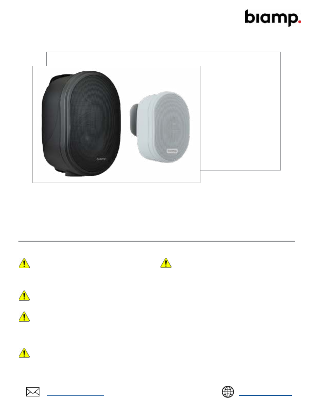
OVO3T / 5T COMMERCIAL LOUDSPEAKER
INSTALLATION GUIDE
Models
OVO3T
OVO5T
Available in black and white
INSTALLATION CONSIDERATIONS
• This guide covers the installation and initial setup of the OVO3T and OVO5T loudspeakers.
• Be sure to read this manual and the Loudspeaker Safety Guide before installing or using product.
• 20-Watts continuous power at 16 Ohm (3T) / 40-Watts continuous power at 16 Ohm (5T).
• The loudspeaker grille is fixed and removing it may cause damage.
• Indoor use only.
Rigging and Electrical Safety
DANGER: Installation of loudspeakers should only be performed by
trained and qualied personnel. It is strongly recommended that a
licensed and certied professional structural engineer approve the
mounting design. Severe injury may occur if these products are improperly
installed! All electrical connections must conform to applicable city, county,
state, and national (NEC) electrical codes.
DANGER: It is possible to experience severe electrical shock from a
power amplier. Always make sure that all power ampliers are in the
“OFF" position and unplugged from an AC Mains supply before
performing electrical work.
IMPORTANT: All electrical installation connections for loudspeaker
lines are subject to all applicable governmental building and re
codes. The selection of appropriate electrical hardware to interface
with the loudspeaker lies solely with the installation professional. Biamp
recommends that an appropriately licensed engineer, electrician, or other
qualied professional identify and select the appropriate conduit, ttings, wire,
etc. for the installation.
DANGER: The output power capabilities of audio ampliers present a
danger to installers. To minimize the risk of electric shock from
loudspeaker connecting cables, conrm that the power ampliers are
turned “o" before connecting loudspeaker cable(s) to the loudspeaker or
amplier. Always follow local electrical codes and proper electrical safety
procedures.
amplier. This is to avoid passing any clicks or pops that may originate in the
upstream devices to the loudspeakers. The amplier should initially be
powered-up with its gain controls turned all the way down. After making sure
that a continuous signal is present, such as a CD playing, slowly raise the level
of the gain controls to establish that the wiring has been installed correctly.
Only then should the loudspeaker be operated at normal output levels.
Wiring and Electrical Safety
The designer must account and compensate for cable losses between the
amplier and the loudspeaker system. Refer to this article on Cornerstone
for more information on cable loss calculations. Please contact the Customer
Support for additional assistance (email: support@biamp.com)
Wire the loudspeaker. Terminate per your local electrical code or requirements.
WARNING: After wiring the amplier(s) to the loudspeaker(s), rst
power-up all devices that are upstream of the amplier, such as
mixers, equalizers, compressor/limiters, etc., before powering-up the
support@biamp.com
support.biamp.com
Page 2

INCLUDED IN THE BOX
OVO3T
• Loudspeakers with integrated pan / tilt brackets x 2.
• Color-matched rubber surface stands x 2.
OVO3T PRODUCT DESCRIPTION
Pan & Tilt
Adjustment Knobs
Mounting Holes
Grille
Mounting Bracket
Tap Switch
Access Cover
Optional
Stand
2
OVO3T / 5T Installation Guide
Page 3

INCLUDED IN THE BOX
OVO5T
• Loudspeakers with U-brackets x 2.
• Color-matched wedge mounts x 2.
OVO5T PRODUCT DESCRIPTION
Pan & Tilt
Adjustment Knob
U-Bracket
Optional Wedge
Mount
Grille
Tap Switch
Access Cover
Pan & Tilt
Adjustment Knob
OVO3T / 5T Installation Guide
3
Page 4

INSTALLATION
OVO3T Stand Mount Option
1. Conrm the loudspeaker installation location (the pan / tilt mount may be removed if required).
2. Place the stand on a at surface and set the loudspeaker on the stand.
3. Connect wires and adjust tap settings (see details here).
4
OVO3T / 5T Installation Guide
Page 5

INSTALLATION CONTINUED
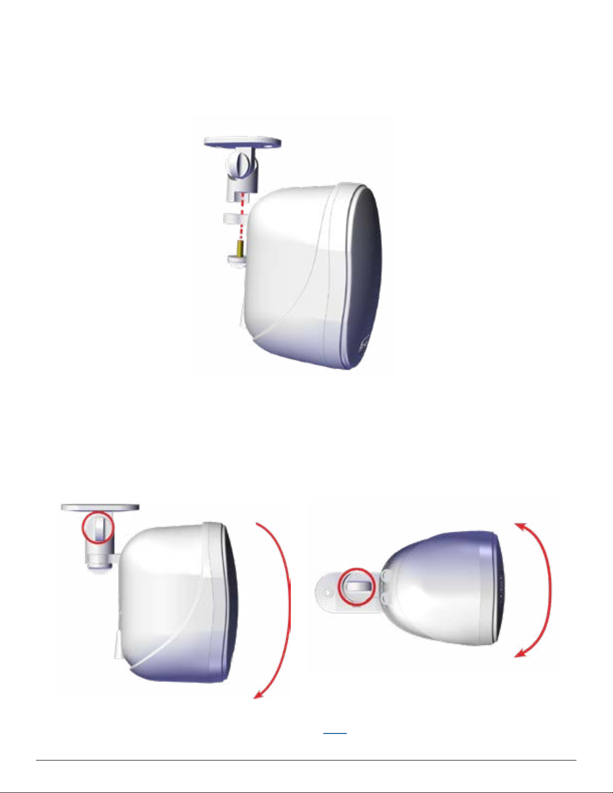
OVO3T Wall Mount Option
The OVO3T features an integrated pan / tilt bracket (hardware for mounting must be purchased
separately). Adjust the tap setting before installation to save time.
1. Conrm the loudspeaker installation location.
2. Unscrew and remove the swivel knob at the top of the speaker to detach the bracket.
3. Connect wires and adjust tap settings (see details here)
4. Use the bracket to mark the hole locations.
5. Attach the bracket to the structure.
OVO3T / 5T Installation Guide
5
Page 6

INSTALLATION CONTINUED
OVO3T Wall Mount Option
6. Reattach the bracket.
7. Adjust the tilt / pan for desired coverage.
- 45° Vertical Tilt in 15° increments
(tilts downward only)
+/- 45° Horizontal Pan
in 22.5° increments.
8. Connect wires and adjust tap settings (see details here).
6
OVO3T / 5T Installation Guide
Page 7

INSTALLATION CONTINUED
OVO3T Ceiling Mount Option
1. Conrm the loudspeaker installation location.
2. Unscrew and remove the swivel knob at the top of the speaker to detach the bracket.
3. Use bracket to mark the hole locations.
4. Attach the bracket to the structure.
OVO3T / 5T Installation Guide
DANGER: The bracket base
MUST be attached to a
structural component above the
ceiling.
NEVER mount the loudspeaker
directly to ceiling surfaces or
drywall only.
7
Page 8
INSTALLATION CONTINUED
OVO3T Ceiling Mount Option
5. Reattach the bracket.
6. Adjust the tilt / pan for desired coverage.
Maximum Tilt is -90° in 22.5°
increments (tilts downward only).
+/- 45° Horizontal Pan
in 22.5° increments.
7. Connect wires and adjust tap settings (see details here).
8
OVO3T / 5T Installation Guide
Page 9

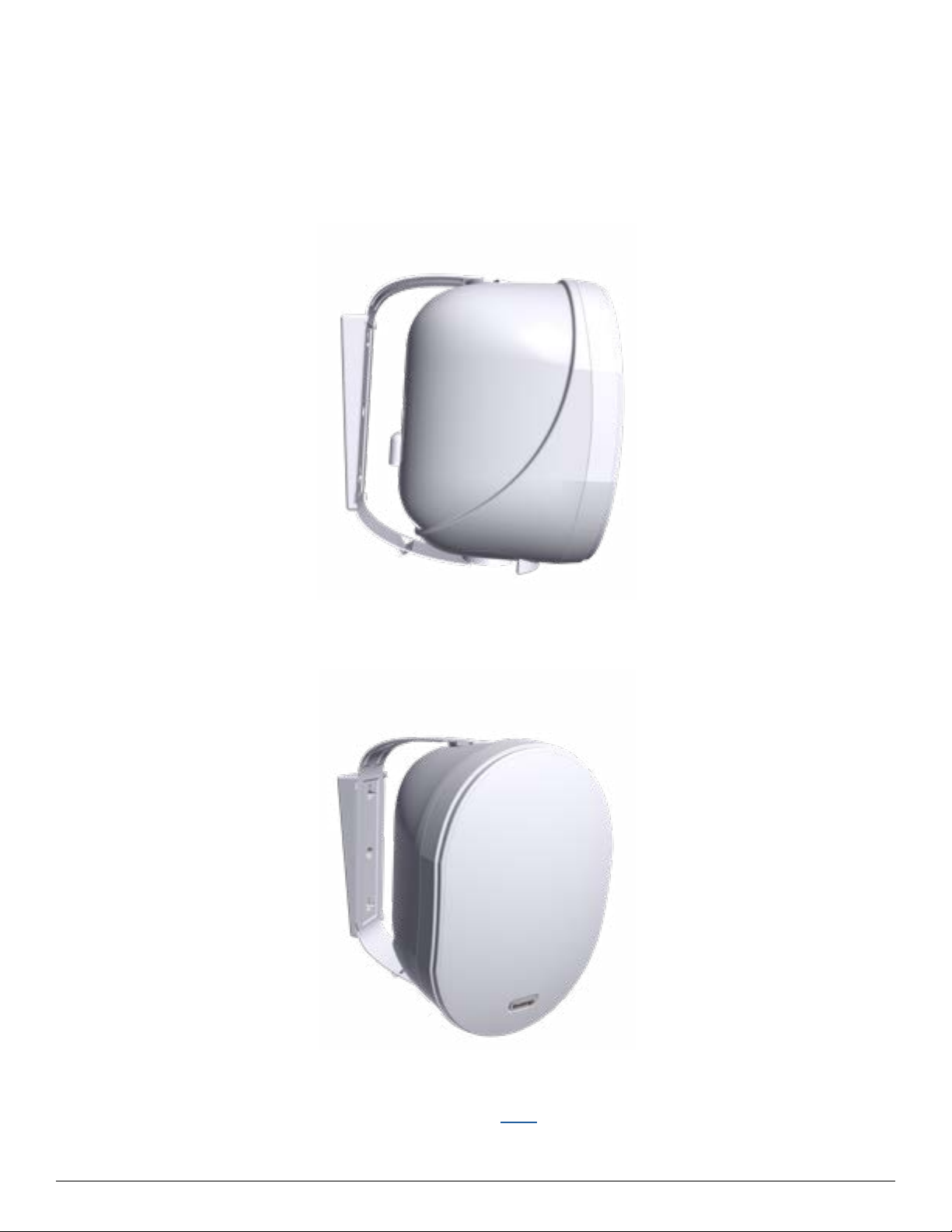
INSTALLATION
OVO5T Surface Mount Option
Each OVO5T comes with an attached U-bracket for easy surface installation (installer must provide the
appropriate hardware for the application. Adjust the tap setting before installation to save time.
1. Conrm the loudspeaker installation location.
2. Attach the loudspeaker to the structure or surface using the holes in the U-bracket (hardware not
provided).
NOTE: The U-bracket can be removed and pre-installed. Reserve the hardware for reattachment
of the horn.
3. Adjust to desired angle and tighten the adjustment knobs.
4. The loudspeaker can also stand on a tabletop or shelf – keep the yoke tight and directly behind
the loudspeaker.
5. Connect wires and adjust tap settings (see details here).
OVO3T / 5T Installation Guide
9
Page 10

INSTALLATION CONTINUED
OVO5T Surface Mount Option
1. Adjust pan / tilt by loosening the knobs on both ends.
+/- 90° horizontal pan in
22.5° increments.
2. Position and tighten the adjustment knobs.
-15° Vertical Tilt (tilts
downward only)
10
OVO3T / 5T Installation Guide
Page 11

INSTALLATION CONTINUED
OVO5T Wedge Mount Option
Attach the U-bracket to the wedge mount for an additional 5” down-tilt.
1. Conrm the loudspeaker installation location.
2. Use wedge to mark the hole locations.
3. Align the wedge with U-bracket and attach to mounting surface (hardware not provided).
NOTE: The U-bracket can be removed and pre-installed. Reserve the hardware for reattachment
of the loudspeaker.
OVO3T / 5T Installation Guide
11
Page 12
INSTALLATION CONTINUED
OVO5T Wedge Mount Option
4. Adjust to desired angle and tighten the knobs.
5. Connect wires and adjust tap settings (see details here).
12
OVO3T / 5T Installation Guide
Page 13
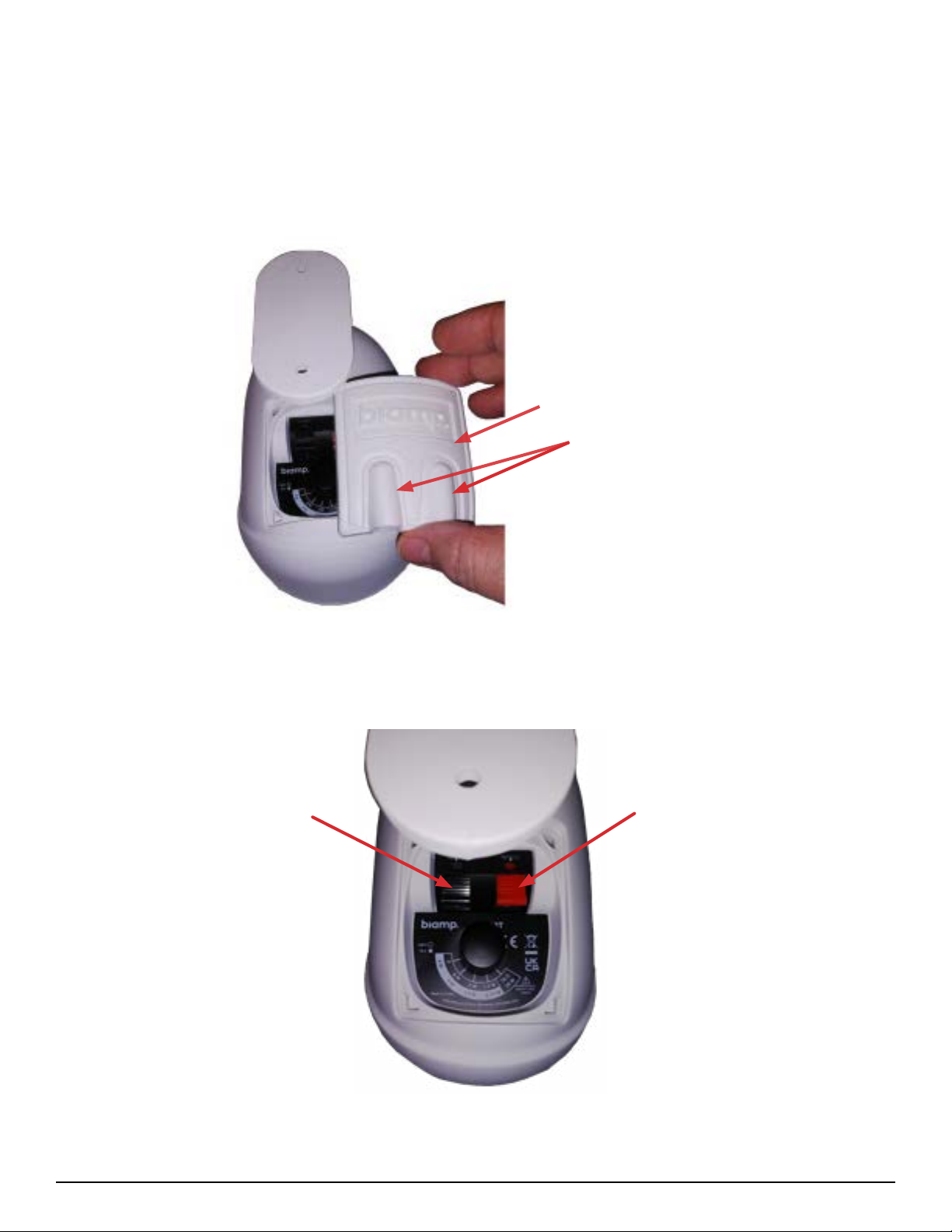
INSTALLATION WIRING
OVO3T Wiring
1. Peel back the tap switch access cover to view the terminals and tap setting knob.
NOTE: Pan or tilt the loudspeaker for easier access to the input panel.
Tap Switch Access Cover
Wire Routing
2. Lift the terminal levers and insert the wires into the correct terminal observing polarity.
Terminal Lever Terminal Lever
3. Press each lever down to secure wires.
OVO3T / 5T Installation Guide
13
Page 14

INSTALLATION WIRING CONTINUED
OVO3T
4. Rotate the knob to select the appropriate tap setting.
5. Reinstall the cover and route the wires through the routing channels at the bottom of the cover.
Press all 4 corners down (and around the edge) to secure the cover.
OVO5T WIRING
1. Pull up on the raised wire routing area and peel back the tap switch access cover to view the
terminals and tap setting knob.
NOTE: Move the U-bracket to the side for easier access to the input panel.
Tap Switch Access Cover
Wire Routing
14
OVO3T / 5T Installation Guide
Page 15

INSTALLATION WIRING CONTINUED
OVO5T
2. Lift the terminal levers to insert the wires into the correct terminal observing polarity.
3. Press lever down to secure wires.
Terminal Lever
4. Rotate knob to set the tap setting.
Terminal Lever
Tap Setting Knob
5. Reinstall the cover and route the wires through the routing channels at the bottom of the cover.
Press all 4 corners down (and around the edge) to secure the cover.
OVO3T / 5T Installation Guide
15
Page 16

PAINTING INSTRUCTIONS
The OVO cabinets have a light paint coat over the
plastic material. They accept almost any type of
latex or enamel (oil based) paint. We recommend
application of two light coats.
IMPORTANT: Do not remove the grille.
Process
1. Remove brackets or mounts from the
loudspeaker to paint separately.
2. Use painter’s or other low-adhesive tape to
mask o the grille and area under the input
cover. NEVER use duct tape as it leaves an
adhesive residue that can be dicult to
remove and that may actually cause damage.
Painter’s or other low-adhesive tape is best.
3. Clean the loudspeaker cabinet with a lightly
dampened cloth. Do not use abrasives such
as sandpaper or steel wool.
4. Apply two or more thin coats of latex or
oil-based paint. Latex paint adheres better if
an oil-based primer is used rst. Spray paint
is best, but a brush may be used with light
coats.
CAUTION: NEVER use abrasives, gasoline,
kerosene, acetone, methyl ethyl ketone (MEK),
paint thinner, harsh detergents or other
chemicals on the loudspeaker. These chemicals and
agents may permanently damage the nish. Some are
also toxic and highly ammable.
IMPORT
grille on removal or re-installation.
IMPORTANT: Blocking the grille holes with paint or
getting any paint on the drivers or internal parts will
affect loudspeaker performance and void the warranty.
IMPORTANT: For applications where certification is
required, ensure that relevant information on the rear
label is not painted over.
You will need:
ANT: Take care not to bend or damage the
• Removable masking tape or painter’s tape
• Machinist scribe tool or knife
• 1.5 mm hex wrench
Useful Tip:
• Use a sharp knife to trim the masking material
close to the edges of the masked areas.
5. Allow paint to fully dry and remove all of the
masking materials and reassemble.
16
OVO3T / 5T Installation Guide
Page 17

CONTACT US
Email: support@biamp.com
Web: support.biamp.com
Warranty: biamp.com/legal/warranty-information
Safety & Compliance: biamp.com/compliance
support@biamp.com
support.biamp.com
 Loading...