

Page 1
COMMERCIAL LOUDSPEAKERS
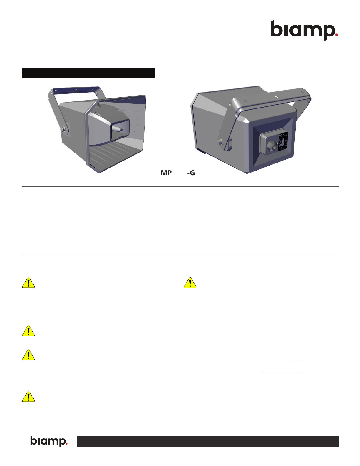
MPLT62-G LONG THROW FULL-RANGE LOUDSPEAKER
Installation and Operation Guide
MPLT62-G
PRODUCT DESCRIPTION
• A horn-loaded full range, 2-way loudspeaker that offers quality sound over long distances in wide areas
• Long-distance projection
• Indoor / Outdoor use
• 70 V/ 100 V operation with 5 tap settings
Rigging and Electrical Safety
DANGER: The loudspeakers described in this manual are designed
and intended to be suspended using a variety of rigging hardware,
means, and methods. Installation of loudspeakers should only be
performed by trained and qualied personnel. It is strongly recommended
that a licensed and certied professional structural engineer approve the
mounting design. Severe injury and/or loss of life may occur if these products
are improperly installed! All electrical connections must conform to applicable
city, county, state, and national (NEC) electrical codes.
DANGER: It is possible to experience severe electrical shock from a
power amplier. Always make sure that all power ampliers are in the
“OFF" position and unplugged from an AC Mains supply before
performing electrical work.
IMPORTANT: All electrical installation connections for loudspeaker
lines are subject to all applicable governmental building and re
codes. The selection of appropriate electrical hardware to interface
with the loudspeaker lies solely with the installation professional. Biamp
recommends that an appropriately licensed engineer, electrician, or other
qualied professional identify and select the appropriate conduit, ttings, wire,
etc. for the installation.
DANGER: The output power capabilities of audio ampliers present a
danger to installers. To minimize the risk of electric shock from
loudspeaker connecting cables, conrm that the power ampliers are
turned “o" before connecting loudspeaker cable(s) to the loudspeaker or
amplier. Always follow local electrical codes and proper electrical safety
procedures.
WARNING: After wiring the amplier(s) to the loudspeaker(s), rst
power-up all devices that are upstream of the amplier, such as mixers,
equalizers, compressor/limiters, etc., before powering-up the amplier.
This is to avoid passing any clicks or pops that may originate in the upstream
devices to the loudspeakers. The amplier should initially be powered-up with its
gain controls turned all the way down. After making sure that a continuous
signal is present, such as a CD playing, slowly raise the level of the gain controls
to establish that the wiring has been installed correctly. Only then should the
loudspeaker be operated at normal output levels.
Wiring and Electrical Safety
The MPLT-62 comes with an attached gland nut. The installer must provide the
cable. The designer must account and compensate for cable losses between
the amplier and the loudspeaker system. Refer to this article on Cornerstone
for more information on cable loss calculations. Please contact the Customer
Support for additional assistance (email: [email protected])
Wire the loudspeaker. A typical installation method is to locate a junction
box (J-box) close to the loudspeaker and connect to it with a shorter cable.
Connections within the J-box should be made with appropriate wire
connectors. Terminate per your local electrical code.
NOTE: Be sure to read the loudspeaker safety guide included in
the carton with the loudspeakers.
A: 9300 S.W. Gemini Drive Beaverton, OR 97008 USA W: www.biamp.com
Page 2
PRODUCT REPRESENTATION
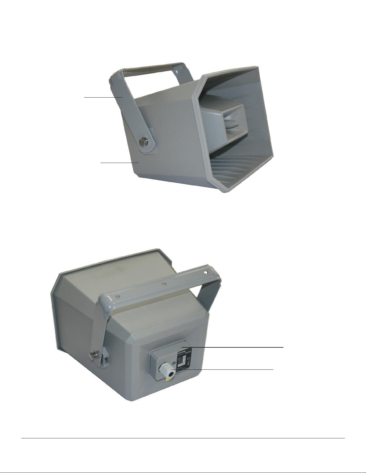
U-bracket
Horn
Figure 1. Front view MPLT-62-G
Input Cover
Gland Nut
Figure 2. Back view MPLT-62-G
page 2 Installation and Operation Guide MPLT62-G
Page 3
INSTALLATION
Each loudspeaker comes with an attached powder-coated aluminum U-bracket for easy surface
installation. The installer must provide the appropriate hardware for the application. The horn and cable
egress are watertight and may be installed indoor or in outdoor applications.
1. Determine where the horn is to be installed.
2. Attach the horn to the structure or surface using the holes in the U-bracket (mounting hardware
not provided).
NOTE: The U-bracket can be removed and pre-installed. Reserve the hardware to reattach to
the horn.
3. Once the horn is installed, attach a safety cable.
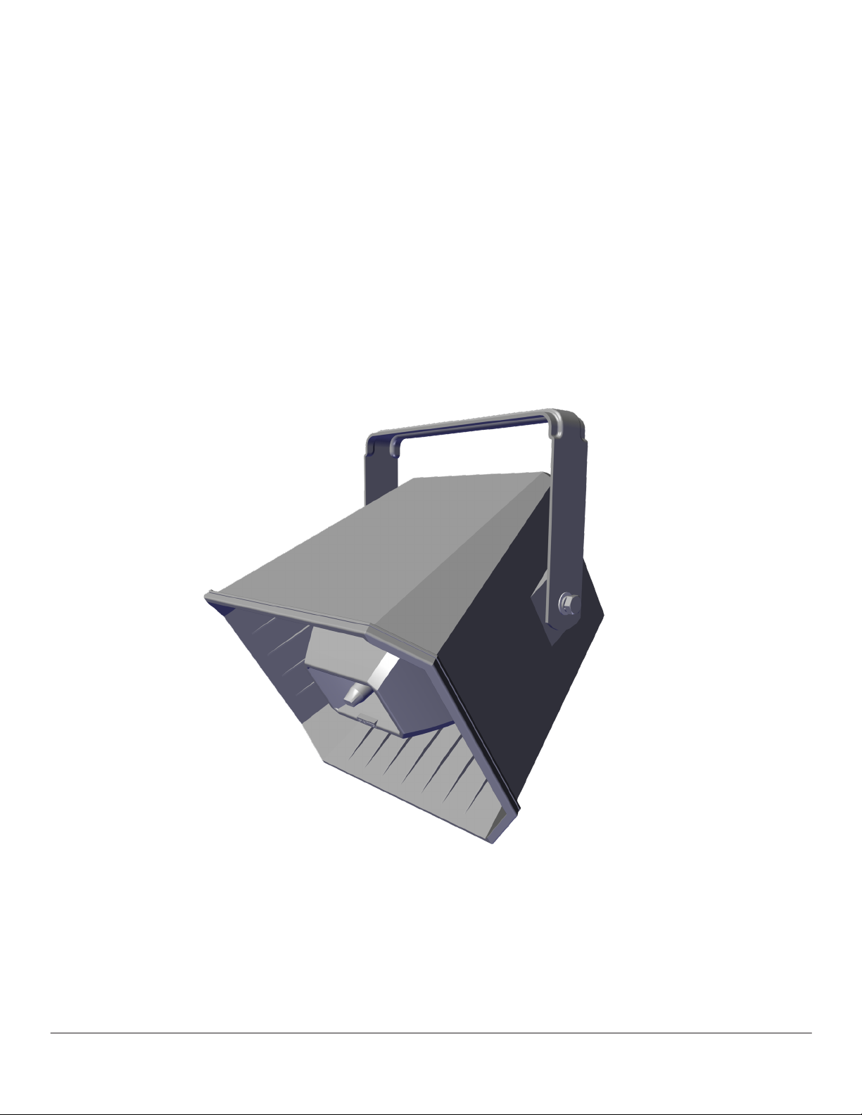
4. Aim the loudspeaker to the desired angle and tighten the bolts on either side to hold it in place.
Figure 3. Position horn
NOTE: The safety cable and associated hardware are not included. Consult all applicable codes for your application. Confer
with a structural engineer for the appropriate cable/hardware for the load, application, and locale. If required, the safety
cable must be secured to a suitable load-bearing point separate from the array mounting, with as little slack as possible, so
as not to develop undue kinetic force if the primary mount were to fail.
MPLT62-G Installation and Operation Guide page 3
Page 4
WIRING / TAP CONNECTION
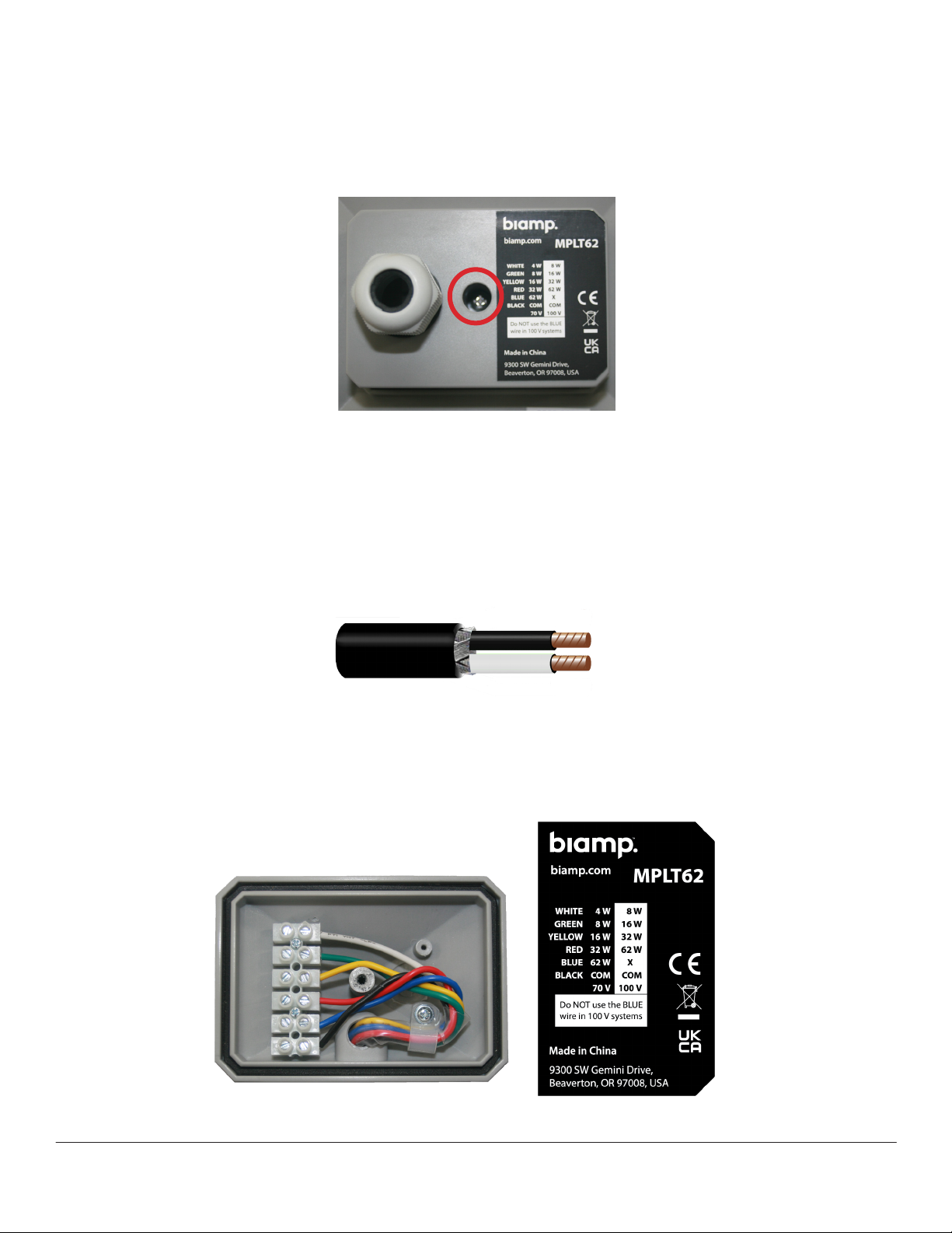
1. Remove the rear input cover (Phillips head screw circled)
2. Loosen the gland nut, and thread a 2-conductor cable through it. The gland nut will accommodate
13-18 mm (0.5-0.7") diameter cable.
Figure 4. MPLT62-G input cover
NOTE: Two or more smaller diameter cables may be used in the gland nut when wiring a
parallel daisy chain of MPLT62-G speakers. Additional precautions may be required to ensure
watertightness of the gland nut. High-quality silicone caulking is typically used in this situation.
3. Strip the ends 6 mm (.25") and prepare the wires for insertion into the barrier strip as shown in
Figure 5.
Figure 5. Typical cable
4. Insert the (+) wire in the appropriate terminal and tighten the screw to hold the wire. Do the same
for the (-) wire to the common (black) location as shown in Figure 6.
5. Choose the appropriate tap setting. See page 5 for an example of tap settings on a line of MPLT-62s.
Figure 6. Connect to the appropriate tap
page 4 Installation and Operation Guide MPLT62-G
Page 5
WIRING / TAP CONNECTION CONTINUED
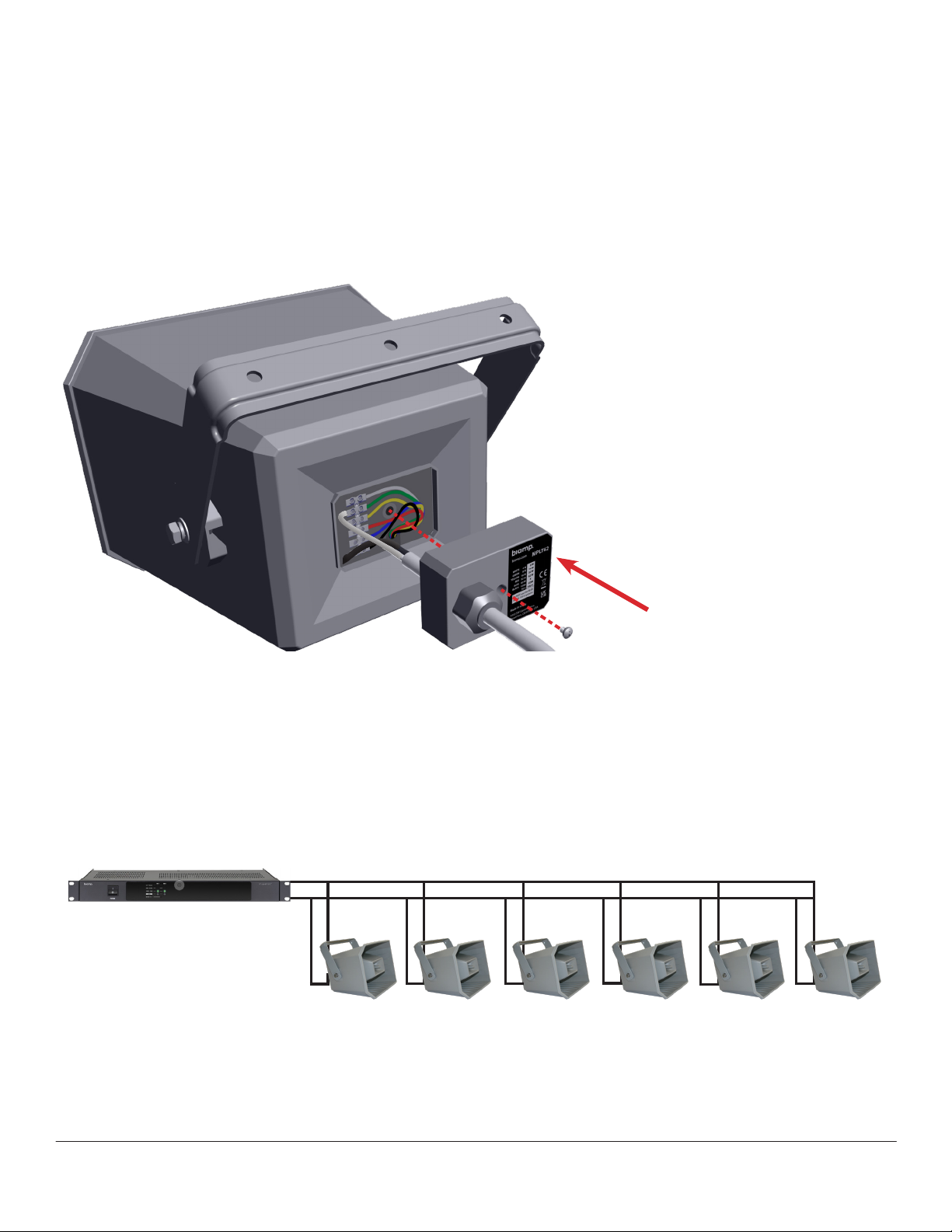
6. Replace the input cover and fully tighten the retaining screw as shown in Figure 7.
7. Tighten the gland nut around the cable, ensuring a weatherproof seal.
8. After all of the horns are installed and connected to the appropriate DSP/amplifier equipment,
power and test the system.
NOTE: For applications requiring a conduit: the
PG21 gland nut can be removed and 1 mm (.50")
NPT fittings can be utilized. Hole diameter is
22.5 mm (.88").
Figure 7. Reattach cover
Amplier power per channel must be higher than total power of all speakers on that channel
120 Watt Amplier
120 W ≥ 32W + 32W + 16W + 16W + 8W + 8W
Figure 8. Typical amp & loudspeakers tab settings
MPLT62-G Installation and Operation Guide page 5
Page 6
OPTIONAL ACCESSORIES
Dual Gang Box Mounting Bracket Kit (SPA-HMB100)
The bracket provides attachment from the horn's U-bracket to
a standard 4-square or dual gang junction box cover (North
America only).
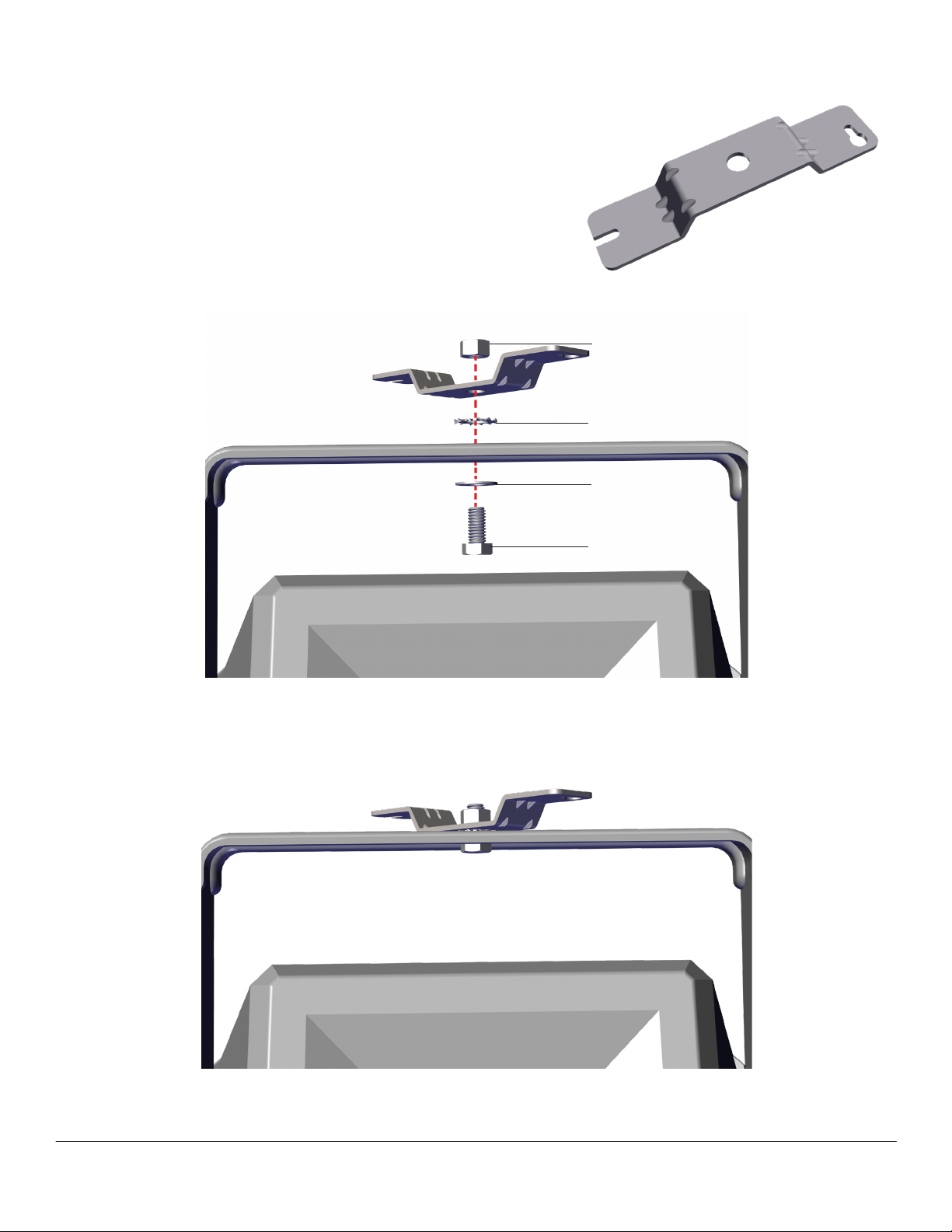
1. Attach the bracket to the horn as shown in Figure 9.
2. Keep the connection loose to allow horn rotation.
Figure 9. Bracket
3/8"-16 Lock Nut
1/2" Lock Washer
3/8" Flat Washer
Figure 10. Bracket install
3/8-16 x 3/4" Screw
Figure 11. Secure bracket to yoke
page 6 Installation and Operation Guide MPLT62-G
Page 7
OPTIONAL ACCESSORIES CONTINUED
Dual Gang Box Mounting Bracket Kit (SPA-HMB100)
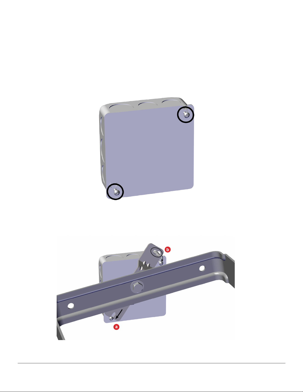
3. Partially install screws (not included) holding the cover on the box as shown in Figure 12.
4. Slide the bracket slot onto the lower screw (a) shown in Figure 13.
5. Rotate and capture the upper bracket keyhole on the top screw (b) in Figure 13.
Figure 12. Loosen screws
Figure 13. Securely attach bracket to box
MPLT62-G Installation and Operation Guide page 7
Page 8
OPTIONAL ACCESSORIES CONTINUED
Dual Gang Box Mounting Bracket Kit (SPA-HMB100)
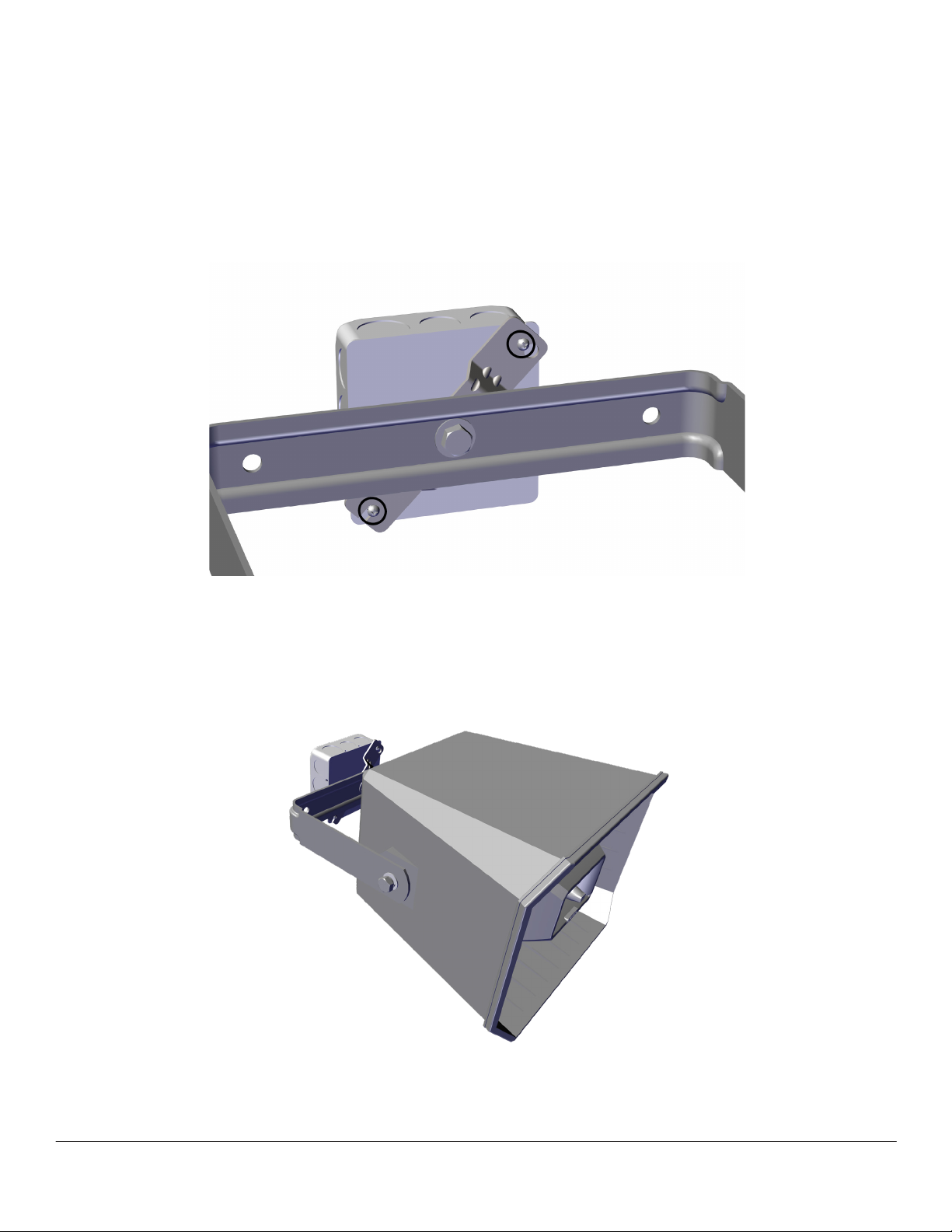
6. Rotate the bracket down to fully capture the screw (circled) in Figure 14.
7. Fully tighten the screws to secure the bracket to the box.
NOTE: Vertically mounted mounted boxes must have the straight bracket slot at the bottom for
security/saftey.
Figure 14. Bracket installed
8. Aim the horn and fully tighten center bracket hardware.
Figure 15. Typical placement
page 8 Installation and Operation Guide MPLT62-G
Page 9
OPTIONAL ACCESSORIES CONTINUED
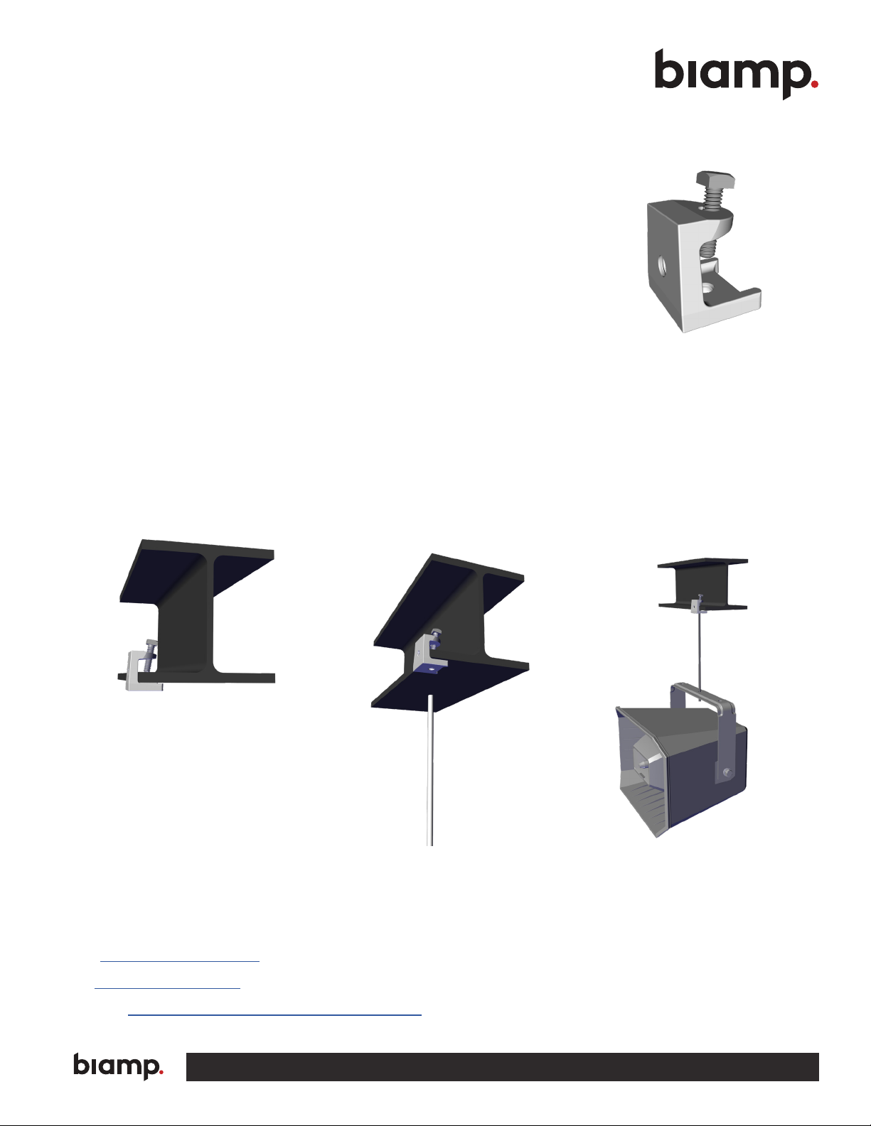
Beam Clamp Installation (SPA-HBC100)
This beam clamp has a 125 lb. (56.6 kg) load capacity.
1. Attach clamp to beam or building structure.
2. Beam clamp supports 1/4" threaded rod as shown in Figure 16.
(rod and horn mounting hardware not included).
3. One or two clamps may be used to suspend the horn. One clamp in the
center position is shown in Figure.17.
4. Position and secure beam clamp to beam or support structure by
tightening the bolt.
5. Secure horn bracket to the rod.
Figure 16. Beam clamp
6. Aim the horn and secure the angle by tightening the side bolts.
7. Install safety cable to a secondary mounting point.
8. Refer to the note on page 3 of this manual.
NOTE: Hardware securing horn to the rod and beam clamp is not shown, must be supplied
by the installer.
Figure 17. Beam clamp attached
Figure 18. Rod attachment
CONTACT US
Email: [email protected]
Web: support.biamp.com
Warranty: biamp.com/legal/warranty-information
A: 9300 S.W. Gemini Drive Beaverton, OR 97008 USA W: www.biamp.com
Figure 19. Typical
horn attachment
28MAR2023
 Loading...