

Page 1

Pendant Hanging Kit (MC-PHK16-12PK)
Installation & Operation Guide
PRODUCT DESCRIPTION
The Pendant Hanging Kit includes pre-cut Magic Cable lengths,
snap-hooks, grippers and connectors that allow an installer
to hang twelve (12) pendant loudspeakers with snap-hook
suspension.
Kit includes:
• 12 Magic Cable Hanging Whips (black or white)
- 16.4' (5m) length [suspension height up to 14.8' (4.5m)]
• 25 Griplock® cable gripper with snap-hook
• 25 Griplock cable grippers
• 25 Scotchlok™ electrical connectors
FEATURES
• Each Magic Cable combines two support cables and a
set of electrical conductors in one color-matched drop
• Easily install the support cable members using the
Griplock connectors and snap-hooks
• Make durable electrical connections with the Scotchlok
connectors
dual-ended cable
connector
Griplock
Black OR White
Magic Cable
Griplock cable
connector
with snap-hook
Scotchlok
electrical
connector
RIGGING AND ELECTRICAL SAFETY
IMPORTANT: Installation of loudspeakers should only be
performed by trained and qualied personnel. All electrical
connections must conform to applicable city, county, state,
and national (NEC) electrical codes.
DANGER: The Magic Cable is rated with a Working Load Limit
(WLL) of 80 lbs (36.3 kg), and the Griplock snap-hooks have a
WLL of 45 lbs (20.4 kg); both with a 5:1 safety margin. No
single rigging tting using the Griplock cable gripping device
should ever be subjected to a load that is greater than 50 lbs
(22.7 kg) [45 lbs (20.4 kg) if using the snap-hooks]. Failure to
heed this warning could result in injury or death!
. DANGER: It is possible to experience severe electrical shock
from a power amplier. Always make sure that all power
ampliers are in the "OFF" position and unplugged from an
AC Mains supply before per forming electrical work.
IMPORTANT: The Magic Cable is intended for installation of
suspended loudspeakers. Biamp does not recommend using
it to hang or suspend other objects.
IMPORTANT: Refer to the sections on installation and
connections later in this manual for additional information on
rigging and electrical safety.
A: 9300 S.W. Gemini Drive Beaverton, OR 97008 USA W: www.biamp.com
IMPORTANT: The Griplock cable locking devices
(connectors and snap-hooks) described in these
instructions are only rated for static indoor installations.
They should not be used to mount the loudspeakers
outdoors or other locations subject to moisture, weather
elements or dynamic loads.
CAUTION: It is strongly recommended that a licensed and
certied professional structural engineer approve the
mounting. Severe injury and/or loss of life may occur if this
product is improperly installed.
DANGER: It is essential that the secondary cable be
secured to a suitable load-bearing point separate from the
primary loudspeaker mounting point, with as little slack as
possible so as not to develop undue kinetic force if the
primary mount were to fail.
IMPORTANT: Magic Cable’s strength members are
hardened stainless steel. Cutting the cables with tools not
rated for such use will damage those tools. You should use
a tool rated for cutting ACSR (Aluminum Conductor Steel
Reinforced) cables such as the Klein J2000-59.
CAUTION: The ends of the stainless steel suppor t
elements are sharp and may cause injury. Please handle
with care.
Page 2

INSTALLATION
There are several methods of installation. All involve
attaching the support cables to, or around, structural
elements. Some of the methods are shown below. Please
use the appropriate method for your application.
VERY IMPORTANT: The Griplock cable locking
devices included with the pendants and described
in these instructions are only rated for static indoor
installations. They should not be used to mount the
loudspeakers outdoors or other locations subject to
moisture, weather elements or dynamic loads.
(+)
(–)
(Wire connections (including a
pass through) shown outside
the junction box to illustrate
Scotchlok connections)
Figure 1a. Support cables can loop around structural
members or through anchored hardware
Support Cable Installation
1. The outside insulation has been slit about 13"
(330mm) with the rip cord exposed to access to the
interior support and audio cable elements on both
ends of the cable. Strip back that outer cover. There
are rip cords in each of the interior elements for easy
removal of the insulation.
2. Pull the rip cords down as far as needed and cut o
any extra cable insulation (Figures 2a , 2b).
Stainless steel
support cables
Rip cords
Figure 1b. A typical installation with wiring connections in
a nearby junction box
1/16" Stainless
steel support
cables
Electrical
conductors
Rip cords
(+) Conductor (–) Conductor
Rip Cord
Figure 2a. Magic Cable cross-section
Figure 2b. Cable stripped
with rip cords showing
page 2 Installation and Operation Guide Pendant Hanging Kit
Page 3
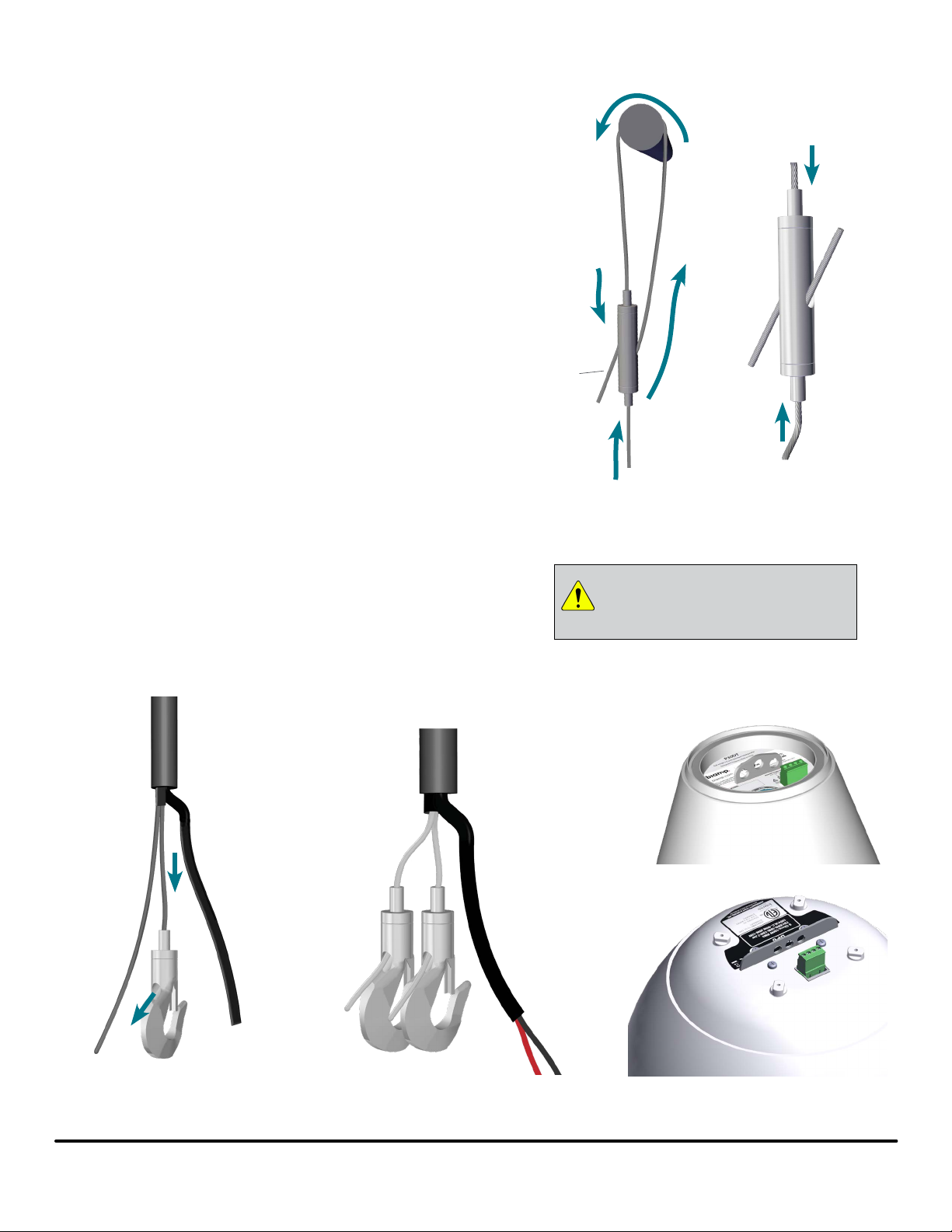
Support Cable Installation (continued)
3. Insert one support cable into the bottom end of a
Griplock and push it up until the end of the wire
protrudes from the side hole (Figure 3a).
4. Pull the end of the cable through the Griplock enough
to either form a loop over the structure or through
structurally anchored hardware and insert back
through the Griplock and out the remaining side hole.
The ends of the Griplock device are spring-loaded
and should be depressed to "unlock" the cable and
allow it to be adjusted.
5. Install the secondary support cable in the same way,
giving it some slack to keep it from bearing weight.
The secondary mount should be close to the primary
one to avoid any kinetic force if the primary mount
should fail. See Figure 1b for reference.
6. Make the lower support cable connection to the
pendants by attaching a griplock snap-hook on the
end of each cable. Roughly determine the length of
the drop and strip back / trim the cable accordingly. If
the cable needs to be threaded through an end cap
before adding the snap-hooks, please do that rst.
7. Insert each cable into the snap-hook cable gripper
and allow at least 1" of cable to extend through the
exit hole to ensure full gripping function.
8. Follow the loudspeaker instructions to connect the
snap-hooks to the loudspeaker. Fully support the
weight of the device until all support connections are
secure.
Structural
support
Griplock
Figure 3a. Cable path
around a support
IMPORTANT: Each cable must extend
at least 1" (25 mm) out the exit hole to
ensure full gripping function.
Figure 3b. Depress
ends to adjust cable
P30DT
DP6
Figure 4a. Insert each cable
into a snap-hook
Figure 4b. Lower cable
end prepared for pendant
loudspeaker connections
Figure 4c. Examples of other
Biamp pendant mounting
brackets
Pendant Hanging Kit Installation and Operation Guide page 3
Page 4

Wiring
Scotchlok connectors are provided for easy
wire connections on the upper end of the
magic cable. Each connector can secure an
input, output and "pass through" wire.
1. Fully insert positive (red) OR negative (black)
conductors into one Scotchlok connector. See Figures
5a and 5b for correct and incorrect insertion.
2. Using pliers, rmly press the oval "plunger" to secure
the wires (Figures 6a, 6b). These are single use
connectors; once the plunger has been depressed the
connector must be replaced if the there is a problem
with the connection.
Note: The connections should be housed in a junction box, but
may not be subject to any force pulling on the wire or stressing the
connectors.
Figure 5a. CORRECT wire
insertion with conductors
inserted all the way to the
end of the connector
Figure 5b. INCORRECT
wire insertion in Scotchlok
connector - conductors not
fully inserted - circuit not
complete
(–)
Negative
Figure 6a. Depress the scotchlok
plunger to fully secure the conductors
CONTACT US
Email: support@biamp.com
Web: support.biamp.com
Figure 6b. Plunger depressed;
conductors secured
(+)
Positive
Typical connection of
conductors (input, putput
and pass through pairs)
Note: Every eort has been made to ensure that the information
contained in this manual was complete and accurate when
printed. However, due to ongoing technical advances, changes or
modications may have occurred that are not covered in this manual.
The latest version is available at support.biamp.com.
585.0079 4MAY2020
page 4 Installation and Operation Guide Pendant Hanging Kit
 Loading...