

Page 1
EN
CONTROL UNIT pag. 10
INSTALLATION AND OPERATION MANUAL
LOG-BC
035393-B_03_10/09/12
Page 2

Index
Page
1. INTRODUCTION 11
2. MAIN FEATURES 11
3. TECHNICAL SPECIFICATIONS 11
4. SAFE INSTALLATION 12
5. POWER 12
5.1 M3 MOTOR + POWER SUPPLY 24 Vac 12
6. INPUT AND OUTPUT CONNECTIONS AND FUNCTIONS 12
6.1 M1 POWER TERMINAL BLOCK 12
6.2 M2 INPUTS CONTROL TERMINAL BLOCK 13
7. DIP-SWITCH CONFIGURATION 13
8. PROGRAMMING 13
8.1 PRELIMINARY CHECKS 13
8.2 CHAIN HEIGHT ADJUSTMENT 13
9. SETTING THE TRIMMERS 14
10. RADIO RECEIVER 14
10.1 RECEIVER TECHNICAL SPECIFICATIONS 14
10.2 RADIO CHANNEL FUNCTIONALITY 14
10.3 ANTENNA INSTALLATION 14
10.4 MANUAL PROGRAMMING 14
10.5 SELF-LEARNING MODE PROGRAMMING 14
11. WORKING WITH A BUFFER BATTERY 16
12. TROUBLESHOOTING GUIDE 16
13. ATTENTION 16
- 10 -
Page 3
EN
LOG-BC
Installation and operation manual
1. INTRODUCTION
The control unit denominated LOG-BC is designed to manage the PRIVEE automation and is equipped with encoder input for
learning the stroke and recognising the obstacle.
Thanks to the considerable amount of logic available even very particular operating conditions on sytems can be met.
2. MAIN FEATURES
- Microprocessor logic
- Green LEDS displaying the status of the N.O. control inputs and red LEDS for the status of the N.C. safety ones
- Pull out terminal blocks
- Output for a ashing light and gate open indicator or for a red and green trafc light
- Integrated radio receiver 433Mhz; 2048 codes
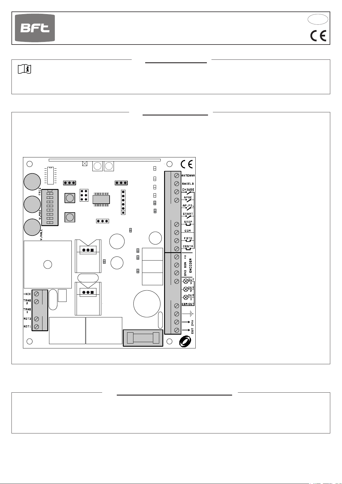
PM1
PM2
PM3
M3
1
2 3 4 5 6 7 8
SW3
ON
START
AP.PD
DL1
μP
PWR
PR1PR2
CHIUDE
APRE
AP.PD.
START
STOP
FOTO
M2
M1: Power terminal board
ENC
M2: Controls and safety devices terminal board
M3: Motor terminal, transformer, +acc
SW3: 8-way Dip Switch
COSTA
OUT 2
F2: Power fuse 500mA 5x20
AP.PD: Semi-automatic opening cycle
START: Start and programming
OUT 1
PM1: Pre-manoeuvre warning lamp ash time
PM2: Chain dip
PM3: Pause time
µP: Microprocessor with ash memory
M1
F2
3. TECHNICAL SPECIFICATIONS
- Power: 230Vac ±10% 50/60 Hz 100W
- SCA output: 24Vac 3 W
- Flashing lamp output 24Vac 25Wmax
- Power supply output for 20 ÷ 26 Vac 12W max.
accessories
- 11 -
Page 4

4. SAFE INSTALLATION
In order to reach the level of safety required by current standards, read the following prescriptions carefully.
Do all the connections on the terminal block, reading the instructions given in this manual carefully and observing the general code of
1)
practice regulating the execution of electrical installations.
Install a four-pole circuit breaker upstream from the installation with a minimum contact opening distance of 3 mm.
2)
Install, wherever it is not foreseen, a differential switch with a 30 mA threshold.
3)
Check effectiveness of the earthing system and connect to it all parts of the automation that have a terminal or earth wire.
4)
There must be at least one signalling device outside, either a trafc light type or a ashing light, together with either a danger or
5)
warning sign.
Apply all the safety devices required by the type of installation, considering the risks it can cause.
6)
Separate the power lines (min. 1,5 mm2 cross section) from the low voltage signal lines (min. 0,5 mm2 cross section) in the ducts.
7)
Jumper the unused NC inputs.
8)
Arrange in series any contacts to be connected to the same NC input.
9)
Arrange in parallel the inputs connected to the same NO input.
10)
Keep radio control or other control devices out of children’s reach, in order to avoid any unintentional automation activation.
11)
5. POWER
(230V)
F N
+ACC
TRAS 2
TRAS 1
MOT2
MOT1
F
230 V ~
N
230V LINE
- Transformer input at 230V 50/60Hz
- Connect the earthing pole in the relevant terminal.
- Power the gear motor via the 3-way terminal
protected by 1A fuse (5x20).
- Utilise an H07RN-F 2x1.5+T min type cable
1A
TRANSFORMER
5.1
MOT1 - MOT2
Motor output 24Vdc. After a power failure, the rst action performed is an opening cycle.
If it fails, stop the automation, take the motor connector out and put it back in the other way around.
TRAS1 - TRAS2
24 Vac input for transformer. Connection to the control unit
is shown in the gure here
+ACC
Do not use
MOTOR + POWER SUPPLY 24 Vac
M3
6. INPUT AND OUTPUT CONNECTIONS AND FUNCTIONS
+
OUT 24V
OUT 1
OUT 2
OUT 3
6.1
OUT 24V
-
Accessories power supply (max 12 W):
24 Vac operations with mains power on.
24 Vdc (out+, 24V-) operation with no main power and optional buffer battery kit. KIT-BATT-SC
SCA 24Vac 3W max
Carriageway open LED that ashes slowly during opening, rapidly during closing, remains lit steady during the stop and
pause phase and switches off when the barrier is closed.
N.B.: The indicator lamp ashes twice to indicate that the automation system has detected an obstacle three consecutive
times while closing. Automatic closing is temporarily disabled and is enabled again only after a subsequent successful
closing cycle.
YELLOW FLASHING LAMP (SL-R-24V-AI) 24Vac 25W max.
Flashing output for self-ashing blinker
NOT USED
POWER TERMINAL BLOCK
M1
- 12 -
Page 5

START
AP. PD
FOTO
STOP
6.2
INPUTS CONTROL TERMINAL BLOCK
M2
FOTO
Safety input with NC contact. During closure, when the photocell ray is interrupted, it immediately opens the gate again.
COM
If this input is kept open by a clock or weekly timer, the automation system closes again after the pause time, if programmed,
and only once the entrance is clear.
STOP
NC safety input. When this is activated it stops the automation instantly and when a start command is then given the gate
COM
will always open. If a stop command is given during pause time it eliminates automatic re-closing, waiting for a command.
START
NO input, allowing the open and close signals to be sent to the automation system. This input is ignored during the opening cycle.
COM
If this input is commanded continuously, the automation system performs the opening cycle and, if the pause time is programmed and only once the entrance is clear, the automatic closing cycle.
AP.PD.
The command is accepted only if the barrier is completely closed, and automatic closing is temporarily disabled during the
COM
opening cycle. Use in accordance with the automatic logic of the start command (DIP 1-2 ON).
APRE
COM
Encoder input SGN-2.
CHIUDE
APRE
COM
CHIUDE
NO input for closing. To close the automation only if the safety devices have not triggered.
7. DIP SWITCH CONFIGURATION
Dip switches 1 and 2: They select the functioning logic
Off-Off: Hold-to-run logic.
The automation works by keeping the commands pressed, acting on the open or close inputs.
The start command opens once and closes once.
On-Off: SEMI-AUTOMATIC (Logic for pulse type collective control)
Open command only. To close after opening, press start or close. Pressing during closing cycle reopens
On-On: AUTOMATIC (Logic for pulse type collective control)
Open command only. Pressing start when paused closes barrier, pressing while barrier is closing opens
Dip switch 3: Selects pre-ashing function.
Off: The pre-ashing function is disabled: the ashing unit is commanded during the manoeuvre.
On: The warning lamp ashes for a period from 2 to 10 seconds (settable from trimmer PM1) before all mano-
Commands via radio in the hold-to-run logic are forbidden by law.
the barrier.
barrier. Barrier is closed after pause time.
euvres except barrier inversion triggered by the safety devices.
8. PROGRAMMING
8.1 PRELIMINARY CHECKS
To guarantee the safety of the system, remember that the automation must be checked according to the risk analysis, therefore the
installer must install any safety accessories needed and resolve all residue risks and dangers that the machine may cause when it
works automatically via the remote controls.
8.2 CHAIN HEIGHT ADJUSTMENT
1) Switch automation system off and on.
2) Set trimmer PM2 (chain dip setting) to the middle setting.
3) Press start and wait. The automation system performs the reset procedure.
4) At the end of the reset procedure, press START again and wait for the closing cycle to conclude.
5) Adjust trimmer PM2 to set the desired chain height and perform an open cycle and a close cycle to check that the height is correct.
- 13 -
Page 6

9. SETTING THE TRIMMERS
PM1: PRE-MANOEUVRE WARNING LAMP FLASH TIME. Sets the pre-manoeuvre warning ash time between 2 and 10 sec.
PM2: CHAIN DIP. Sets chain height. Turn clockwise to increase height.
PM3: PAUSE TIME. Sets the pause time between 2 and 120 sec.
10. RADIO RECEIVER
10.1 RECEIVER TECHNICAL SPECIFICATIONS
- Max. n° of radio transmitters that can be memorized: 64
- Frequency: 433.92MHz
- Code by means of: Rolling-code algorithm
- N° of combinations: 4 billion
10.2 RADIO CHANNEL FUNCTIONALITY
Channel 1: START command
Channel 2: AP.PD command (Semi-automatic opening cycle)
10.3 ANTENNA INSTALLATION
Use an antenna tuned to 433MHz. Connect the tuned antenna to the antenna terminals using RG58 coaxial cable .
antenna cable RG58
ANTENNA
SHIELD
10.4 MANUAL PROGRAMMING
In the case of standard installations where no advanced functions are required, it is possible to proceed to
manual storage of the transmitters, making reference to programming table A and to the example for basic
programming.
1) If you wish the transmitter to activate output 1, press pushbutton PR1, otherwise if you wish the
transmitter to activate output 2, press pushbutton PR2.
2) When LED DL1 starts blinking, press hidden key on the transmitter, LED DL1 will remain continuously lit.
3) Press the key of the transmitter to be memorized, LED DL1 will ash quickly to indicate that it has been
memorized successfully. Flashing as normal will then be resumed.
4) To memorize another transmitter, repeat steps 2) and 3).
5) To exit memorizing mode, wait for the LED to go off completely or press the key of a remote control that
has just been memorized.
IMPORTANT NOTE: ATTACH THE ADHESIVE KEY LABEL TO THE FIRST MEMORISED TRANSMITTER
(MASTER).
In the case of manual programming, the rst transmitter assigns the key code to the receiver; this code is
necessary in order to carry out subsequent cloning of the radio transmitters.
Hidden key
10.5 SELF-LEARNING MODE PROGRAMMING
This mode is used to copy the keys of a transmitter already stored in the receiver memory, without accessing the receiver.
The rst transmitter is to be memorised in manual mode (see paragraph 10.4).
a) Press hidden key on the transmitter already memorised.
b) Press key T on the transmitter already memorised, which is also to be attributed to the new transmitter.
c) Within 10 s., press hidden key on the new transmitter to be memorised.
d) Press key T to be attributed to the new transmitter.
e) To memorise another transmitter, repeat the procedure from step (c) within a maximum time of 10
seconds, otherwise the receiver exits the programming mode.
f ) To copy another key, repeat from step (a), having waited for the receiver to exit the programming mode
(or after disconnecting the receiver from the power supply).
- 14 -
Hidden key
T1
T3
T2
T4
Page 7

- 15 -
Page 8

11. WORKING WITH A BUFFER BATTERY
KIT-BATT-SC allows the automation system to operate even when the mains power supply is disconnected for a short time.
Consult the KIT-BATT-SC installation manual.
12. TROUBLESHOOTING GUIDE
1) The chain drops by a few centimetres at the end of the close cycle.
At the end of the rst close cycle, the control unit determines the force necessary to be applied with the electronic brake and the
excessive dip will be compensated when subsequent close cycles are performed.
2) The barrier is reopened by the automation system during a close cycle, even though there are no obstacles and the photocell beams
are not interrupted.
The chain height setting is too high. Reduce the setting with trimmer PM2.
13. ATTENTION
You are recommended to full an installation that includes all the accessories required to guarantee operation according to current
standards and always using original devices.
These devices must be used and installed in strict compliance with the instructions supplied by the manufacturer, who cannot be held
liable for any damages deriving from improper or unreasonable use.
The manufacturer declines all forms of liability with regard to any errors possibly written in this handbook and reserves the right to add
any modications considered necessary at any time without notice.
- 16 -
Page 9

NOTE
NOTES
REMARQUES
ANMERKUNGEN
NOTAS
INSTALLATORE
INSTALLER
INSTALLATEUR
INSTALLATEUR
INSTALATOR
035393BFT_03_10/09/12
 Loading...