

Page 1
8
027908 412614
QUADRO COMANDO
CONTROL PANEL
CENTRALE DE COMMANDE
SELBSTÜBERWACHENDE STEUERUNG
CUADRO DE MANDOS
BEDIENINGSPANEEL
D811893 00100_02 04-12-12
LEO B CBB 3 230 L02
MONTAGEANLEITUNG
ISTRUZIONI DI INSTALLAZIONE
INSTALLATION MANUAL
INSTRUCTIONS D’INSTALLATION
INSTRUCCIONES DE INSTALACION
INSTALLATIEVOORSCHRIFTEN
Attenzione! Leggere attentamente le “Avvertenze” all’interno! Caution! Read “Warnings” inside carefully! Attention! Veuillez lire attentivement les Avertissements qui se trouvent à l’intérieur! Achtung! Bitte lesen Sie
aufmerksam die „Hinweise“ im Inneren! ¡Atención¡ Leer atentamente las “Advertencias”en el interior! Let op! Lees de “Waarschuwingen” aan de binnenkant zorgvuldig!
LEO B CBB 3 230 L04
LEO B CBB 3 120 F02
LEO B CBB 3 120 F04
Page 2
I
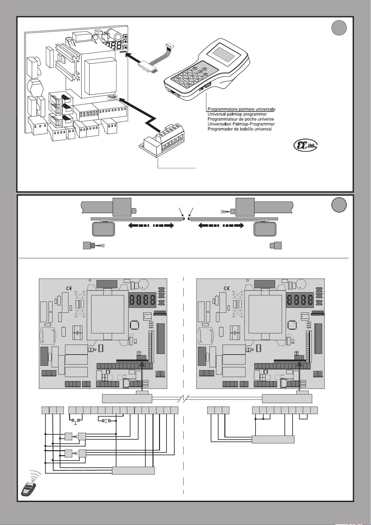
NSTALLAZIONE VELOCE-QUICK INSTALLATION-INSTALLATION RAPIDE
SCHNELLINSTALLATION-INSTALACIÓN RÁPIDA - SNELLE INSTALLATIE
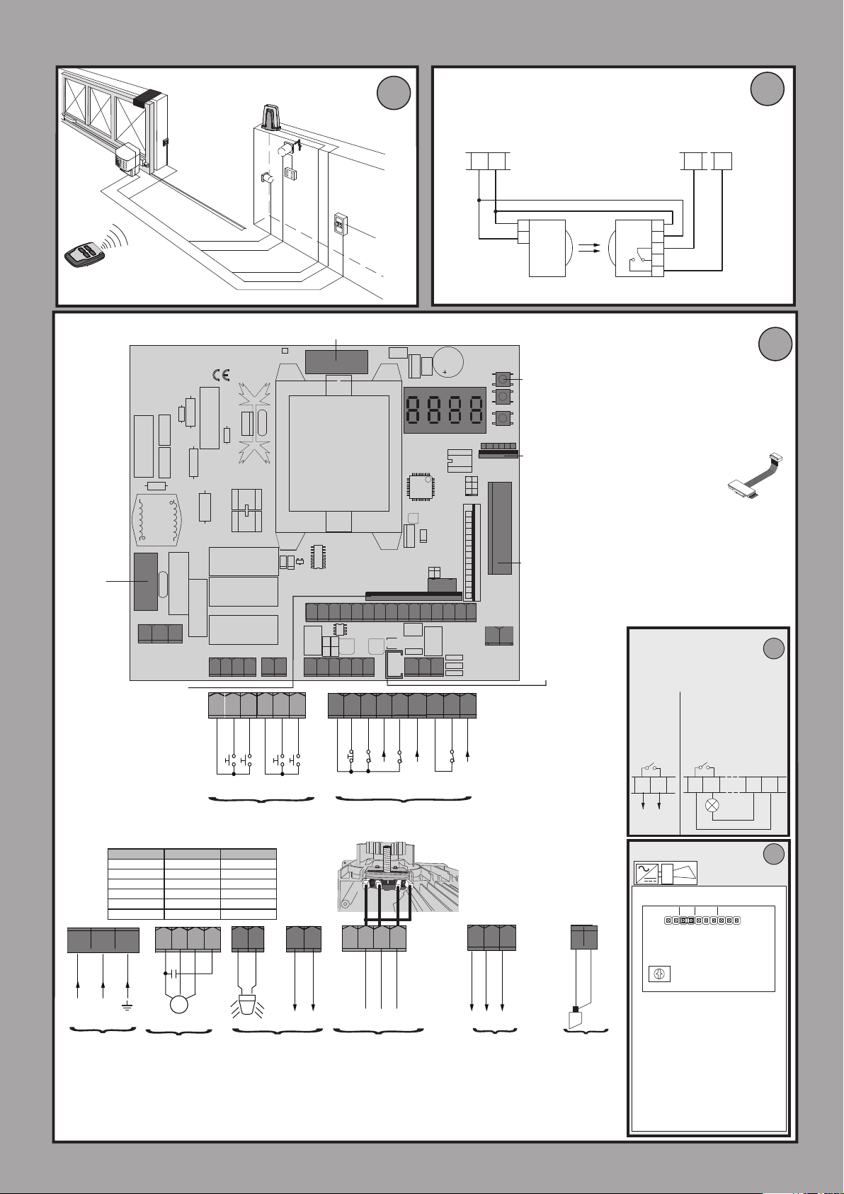
Collegamento di 1 coppia di fotocellule non vericate,
Connection of 1 pair of non-tested photocells,
A
2
5x0,5mm
Connexion 1 paire photocellules no vériées,
Anschluss von einem Paar nicht überprüften Fotozellen,
Conexión de 1 par fotocélulas no comprobadas,
Aansluiting van 1 paar fotocellen anders dan “trusted device”.
JP3
24V ~
SAFE 1 = 0
725150 70
C
D811893 00100_02
3x1.5mm
2x0.5mm
3x0.5mm
2
2
2x1.5mm
RG58
3x1.5mm
2
2
2
F1= 315mAT LEO B CBB 3 230 L02/L04
F1= 630mAT LEO B CBB 3 120 F02/F04
F2= 6,3 AF LEO B CBB 3 230 L02/L04
F2= 10 AF LEO B CBB 3 120 F02/F04
GND
L N
10
11 1213 20 21 26
Connettore scheda opzionale
Optional board connector
Connecteur carte facultative
Steckverbinder Zusatzkarte
Conector de la tarjeta opcional
Connector optionele kaart
M B N
MARRONE BLU NERO
BROWN BLUE BLACK
MARRON BLEU NOIR
BRAUN BLAU SCHWARZ
MARRÓN AZUL NEGRO
BRUIN BLAUW ZWART
11
10
GND
L N
M B N
Commandes /Bedienelemente
12
62
60 61
Comandi / Commands
Mandos/ Commando's
13
COM
IC 1
NO
20
max 40W
IC 2
NO
21
230V
63
c
L
N
Alimentazione
Power supply
Alimentation
Stromversorgung
Alimentación
Voeding
**Con logica inversione direzione di apertura = 000 (DIR=DX) / **With reverse logic, opening direction = 000 (DIR=right)
** Avec logique inversion direction d’ouverture = 000 (DIR=DRT) / **Mit Inversionslogik Önungsrichtung = 000 (DIR=rechts)
**Con lógica inversión dirección de apertura = 000 (DIR=DER) / **Met logica omkering openingsrichting = 000 (DIR=R)
M
Motore / Motor
moteur/Motor
Eindaanslag/Motor
60 6162 6364 6570 71 7273 7475 7677 78
27 4041 4243 50 51 52
71
70
COM
64
65
IC 3
IC 4
NO
NO
26
27
72
73
SAFE 1
COM
STOP
NC
NC
Sicurezze / Safety devices
Sécurités / Sicherheitsvorrichtungen
Dispositivos de seguridad / Veiligheden
40
41
42
+ REF SWE
SWC **
*
AUX
Ingressi necorsa
Limit switch inputs
Entrées des ns de course
Eingänge Anschlag
Entradas nales de carrera
Ingangen
74 75
FAULT 1
SAFE 2
NC
43
SWO **
Y #
76 77
78
FAULT 2
FAULT 3
SAFE 3
COM
NC
52
50
51
24V +
24V -
Alimentazione accessori
Accessories power supply
Alimentation des accessoires
Stromversorgung Zubehör
Alimentación accesorios
Voeding accessoires
24 VSafe+
2 - LEO B CBB 3 230 L02/L04 - LEO B CBB 3 120 F02 / F04
1
TX1
2
RX1
1
2
3
4
5
B
Display + tasti programmazione
Display + programming keys
Acheur + touches programmation
Display + Programmierungstasten
Pantalla + botones programación
Display + programmeringstoetsen
Connettore programmatore palmare,
Palmtop programmer connector,
Connecteur programmateur de poche,
Steckverbinder Palmtop-Programmierer,
Conector del programador de bolsillo,
Connector programmeerbare palmtop.
Connettore per ricevente radio
(vedi paragrafo corrispondente).
Radio-receiver connector (see relevant section).
Connecteur pour récepteur radio (cf. paragraphe correspondant).
Steckverbindung für Funkempfänger (siehe entsprechenden Abschnitt).
Conector para receptor radio (véase apartado correspondiente).
Connector voor radio-ontvanger (zie bijbehorende paragraaf).
Connettore encoder
Encoder connector
Connecteur encodeur
Steckverbindung Encoder
Conector encoder
Stekker encoder
Y #
ANT
Antenna
Antenne
Antena
Antenne
* LEO B CBB 3 230 L02
LEO B CBB 3 230 L04
LEO B CBB 3 120 F04
AUX 3 MAX 24V 0,5A
AUX 3 = 0
AUX 3 = 2
AUX 3 = 3
AUX 3 = 4
AUX 3 = 5
AUX 3 = 6
AUX 3 = 7
AUX 3 = 8
26
27
* LEO B CBB 3 120 F02
ALARM
SHIELD
SOUND PATTERN
SELECTION
1 CONTINUOUS link A
2 LONG PIP link A & E
3 SHORT PIP link A & D
4 SHRIEK 1 link A B D
5 SHRIEK 2 link A C E
6 WARBLE 1 link A & B
7 WARBLE 2 link A & C
8 TWO TONE 1 link B
9 TWO TONE 2 link C
AUX 3 = 1
26 27 50 51
SCA
ALARM
24 Vd.c.
A B C D E
SOUND PATTERN
SELECTION
VOLUME CONTROL
1
24 V~
2
Page 3
language
dir
preset
autoset
x1
*
rh
lh
AR
sr
ac
sc
ind
. . . . . .
ITA
fra
deu
eng
esp
SIMPLIFIED MENU
OPEN
rh
lh
ar: automatic operation,
residential
sr: semiautomatic operation,
residential
ac: automatic operation,
commercial
Sc: semiautomatic operation,
commercial
Ind:dead man operation
OPEN
MIN 1 - MAX 3
AUTO OPEN
PRESET DEFAULT
PARAMETERS
Opening operation time [s]
Closing operation time [s] 300 Set by autoset*
Automatic closing time [s]
Time-to-clear trac light zone [s]
Slow-down distance during opening [%]
Slow-down distance during closing [%] 30 Set by autoset*
Partial opening 20 20 20 20 20 20
Leaf force during opening [%]
Leaf force during closing [%]
Leaf/leaves force during opening during
slow-down
[%]
Leaf/leaves force during closing during
slow-down [%]
Braking[%]
LOGIC
Automatic Closing Time 0 1 0 1 0 0
Fast closing 0 0 0 0 0 0
Step-by-step movement 0 1 0 1 0 0
Encoder 2 2 2 2 2 2
Pre-alarm 0 0 0 1 1 0
Deadman 0 0 0 0 0 1
Block pulses during opening 0 0 0 1 1 0
Block pulses during TCA 0 0 0 0 0 0
Block pulses during closing 0 0 0 0 0 0
Open in other direction
SAFE 1 0 / / / / /
SAFE 2
SAFE 3 2 / / / / /
IC 1 0 / / / / /
IC 2 4 / / / / /
IC 3 2 / / / / /
IC 4 3 / / / / /
AUX 3* 0 / / / / /
Fixed code 0 0 0 0 0 0
Transmitter programming 1 1 1 1 1 1
Serial mode 0 0 0 0 0 0
Address 0 0 0 0 0 0
EXPI1 1 / / / / /
EXPI2 0 / / / / /
EXPO1 9 / / / / /
EXPO2 9 / / / / /
Trac light pre-ashing 0 0 0 0 0 0
(75***)
(75***)
ar sr ac sc ind
300 Set by autoset*
40 40 40 40 40 40
40 40 40 40 40 40
30 Set by autoset*
41
41
75 Set by autoset*
75 Set by autoset*
0 Set by autoset*
0 / / / / /
6 / / / / /
Set by autoset*
Set by autoset*
D811893 00100_02
o o
e
re otes
hidden button
end
4 - LEO B CBB 3 230 L02/L04 - LEO B CBB 3 120 F02 / F04
AUTO CLOSE
release O 01
desidered button
* Only active on LEO B CBB 3 230 L02
** Not active on LEO B CBB 3 120 F02
*** Setup for LEO B CBB 3 120 F02, LEO B CBB 3 230 L04, LEO B CBB 3 120 F04
Scroll up
Scroll down
Conrm/Switch
on display
Exit Menù
Page 4
D811893 00100_02
1
TEST OFFTEST ON
SAFE1 = 0,2,4
2
SAFE1 = 1,3,5
5
SAFE1 = 8
1 PHOT / 1 PHOT OP / 1 PHOT CL
51
50
1 PHOT / 1 PHOT OP / 1 PHOT CL
52
50
52
50
52
50
SAFE 1
1
1
TX1 RX1
TX1 RX1
2
2
1
1
TX1 RX1
TX1 RX1
2
2
2 PHOT / 2 PHOT OP / 2 PHOT CL
1
1
TX1 RX1
TX1 RX1
2
2
1
1
TX2 RX2
TX2 RX2
2
2
52
50
24V -
24V -
51
24V +
24V +
24 VSafe+
24 VSafe+
72
71
71
74 75
STOP
STOP
NC
NC
SAFE 1
SAFE 1
NC
NC
73
73
FAULT 1
FAULT 1
74 75
SAFE 2
SAFE 2
NC
NC
FAULT 2
FAULT 2
70
70
COM
COM
3
1
1
51
2
2
50
3
3
70
4
4
5
5
72
SAFE1 = 6
5
1
1
51
2
2
50
3
3
70
4
4
73
5
5
72
51
1
1
2
2
50
3
3
4
4
70
72
5
5
1
1
51
2
2
50
3
3
73
4
4
70
5
5
SAFETY EDGE
70
72
BAR 8K2
SAFE1 = 7
SAFETY EDGE
77
76
78
SAFE 3
FAULT 3
COM
NC
NC
1 BAR
51
6
6
72
5
5
4
4
70
3
3
2
2
50
51
1
1
1 BAR
52
6
6
72
5
5
73
4
4
70
3
3
2
2
50
51
1
1
2 BAR
52
6
6
72
5
5
70
4
4
3
3
2
2
50
51
1
1
52
6
6
70
5
5
73
4
4
3
3
2
2
50
51
1
1
8,2Kohm 5%
Bar 1
Bar 1
Bar 1
Bar 1
Bar 1
Bar 1
Bar 2
Bar 2
D
1
TEST OFFTEST ON
SAFE2 = 0,2,4
2
SAFE2 = 1,3,5
5
SAFE2 = 8
1
TEST OFFTEST ON
SAFE3 = 0,2,4
2
SAFE3 = 1,3,5
1 PHOT / 1 PHOT OP / 1 PHOT CL
51
1
1
TX1 RX1
TX1 RX1
2
2
50
1 PHOT / 1 PHOT OP / 1 PHOT CL
1
1
52
TX1 RX1
TX1 RX1
2
2
50
2 PHOT / 2 PHOT OP / 2 PHOT CL
1
1
52
TX1 RX1
TX1 RX1
2
2
50
52
1
1
TX2 RX2
TX2 RX2
50
2
2
SAFE 3
1 PHOT / 1 PHOT OP / 1 PHOT CL
51
1
1
TX1 RX1
TX1 RX1
2
2
50
1 PHOT / 1 PHOT OP / 1 PHOT CL
1
1
52
TX1 RX1
TX1 RX1
2
2
50
2 PHOT / 2 PHOT OP / 2 PHOT CL
1
1
52
TX1 RX1
TX1 RX1
2
2
50
52
1
1
TX2 RX2
TX2 RX2
50
2
2
SAFE 2
SAFE2
3
1
1
51
2
2
50
3
3
70
4
4
5
5
74
SAFE2 = 6
4
1
1
51
2
2
50
3
3
70
4
4
75
5
5
74
51
1
1
2
2
50
3
3
4
4
70
74
5
5
1
1
51
2
2
50
3
3
75
4
4
70
5
5
SAFETY EDGE
70
74
BAR 8K2
SAFE2 = 7
SAFETY EDGE
3
1
1
51
2
2
50
3
3
76
4
4
5
5
77
SAFE3 = 6
4
1
1
51
2
2
50
3
3
76
4
4
78
5
5
77
51
1
1
2
2
50
3
3
4
4
76
77
5
5
1
1
51
2
2
50
3
3
78
4
4
76
5
5
SAFE3 = 7
1 BAR
51
6
6
74
5
5
4
4
70
3
3
2
2
50
51
1
1
1 BAR
52
6
6
74
5
5
75
4
4
70
3
3
2
2
50
51
1
1
2 BAR
52
6
6
74
5
5
70
4
4
3
3
2
2
50
51
1
1
52
6
6
70
5
5
75
4
4
3
3
2
2
50
51
1
1
8,2Kohm 5%
1 BAR
51
6
6
77
5
5
4
4
76
3
3
2
2
50
51
1
1
1 BAR
52
77
78
76
50
51
2 BAR
52
77
76
50
51
52
76
78
50
51
6
6
5
5
4
4
3
3
2
2
1
1
6
6
5
5
4
4
3
3
2
2
1
1
6
6
5
5
4
4
3
3
2
2
1
1
Bar 1
Bar 1
Bar 1
Bar 1
Bar 1
Bar 1
Bar 2
Bar 2
Bar 1
Bar 1
Bar 1
Bar 1
Bar 1
Bar 1
Bar 2
Bar 2
LEO B CBB 3 230 L02/L04 - LEO B CBB 3 120 F02 / F04 - 9
Page 5
EE
UNIDA
Programmeerbare Universele Palmtop
(versione x.40 e successive)
(x.40 and later versions)
(version x.40 et suivantes)
(Version x.40 und nachfolgende)
(versión x.40 y sucesivas )
(versie x.40 en hoger)
iNDIRIZZO=0
address=0
adresse=0
adresse=0
direccion=0
modo seriale=2
serial mode=2
mode serie=2
serieller modus=2
modo seria=2
iNDIRIZZO=0
address=0
adresse=0
adresse=0
direccion=0
modo seriale=3
serial mode=3
mode serie=3
serieller modus=3
modo seria=3
TX2 (PHOT)
M1
MASTER
RX1 (PHOT)
SCHEDA DI ESPANSIONE
EXPANSION BOARD
CARTE D’EXPANSION
ERWEITERUNGSKARTE
TARJETA DE EXPANSIÓN
UITBREIDINGSKAART
CC1
(BAR)
CC2
(BAR)
TX1 (PHOT)
M2
SLAVE
RX2 (PHOT)
ESEMPIO APPLICAZIONE ANTE CONTRAPPOSTE CON 2 PHOT E 2 BAR - SAMPLE APPLICATION WITH OPPOSITE LEAVES WITH 2 PHOT AND 2 BAR
- EXEMPLE D’APPLICATION VANTAUX OPPOSÉS AVEC 2 PHOT ET 2 BAR - ANWENDUNGSBEISPIEL EINANDER ENTGEGENGESETZTE TORFLÜGEL
MIT 2 PHOT UND 2 BAR - VOORBEELD TOEPASSING TEGENOVERGESTELDE VLEUGELS MET 2 PHOT EN 2 BAR
D811893 00100_02
F
GND
L N
10
50 51 52 6160
TX1 RX1
TX2
MASTER
60 6162 6364 6570 71 727374 75 7677 78
11 1213 20 21 26
27 4041 4243 50 51 52
B EBA 201 R01
62 63 64 65 70 71 72 73 74 75 76 77 78
START
RX2
STOP
CC1
SAFE 1 = 1
SAFE 2 = 7
SAFE 3 = 1
Y #
MAX 250m
L N
GND
50 51 52
10
11 1213 20 21 26
SLAVE
60 6162 6364 6570 71 727374 75 7677 78
Y #
27 4041 4243 50 51 52
B EBA 201 R01
70 71 72 73 74 75 76 77 78
CC2
SAFE 2 = 7
10 - LEO B CBB 3 230 L02/L04 - LEO B CBB 3 120 F02 / F04
Page 6

G
D811893 00100_02
verso di apertura: destra
opening direction: right
sens de l’ouverture : droite
Önungsrichtung: rechts
sentido de apertura: derecha
openingsrichting: rechtsverso
1
DIR= dK
Inversione direzione di aperura: 000
Open in other direction: 000
Inversion direction de l'ouverture: 000
Richtungsumkehrung Önung: 000
Inversión dirección de apertura: 000
Openingsrichting omdraaien: 000
DIR= sK
Inversione direzione di aperura: 001
Open in other direction: 001
Inversion direction de l'ouverture: 001
Richtungsumkehrung Önung: 001
Inversión dirección de apertura: 001
Openingsrichting omdraaien: 001
2
verso di apertura: sinistra
opening direction: left
sens de l’ouverture : gauche
Önungsrichtung: links
sentido de apertura: izquierda
openingsrichting: links
- Nel passaggio di congurazione logica da apertura destra/sinistra, non invertire il collegamento originale dei morsetti 42-43.
- When switching logic conguration from right to left opening, do not swap over original connection of terminals 42-43.
- Lors du passage de conguration logique de l’ouverture droite/gauche, n’inversez pas la connexion d’origine des bornes 42-43
- Bei der Änderung der Logik Önung rechts/links nicht den Originalanschluss der Klemmen 42-43 verändern.
- En el paso de conguración lógica de apertura derecha/izquierda no invertir la conexión original de los bornes 42-43.
- Bij de overgang van de logica conguratie van rechts/links openen, de oorspronkelijke aansluiting van de klemmen 42-43 niet
omdraaien.
LEO B CBB 3 230 L02/L04 - LEO B CBB 3 120 F02 / F04 - 11
Page 7
x 2
D811893 00100_02
hALT
follow the
user guide
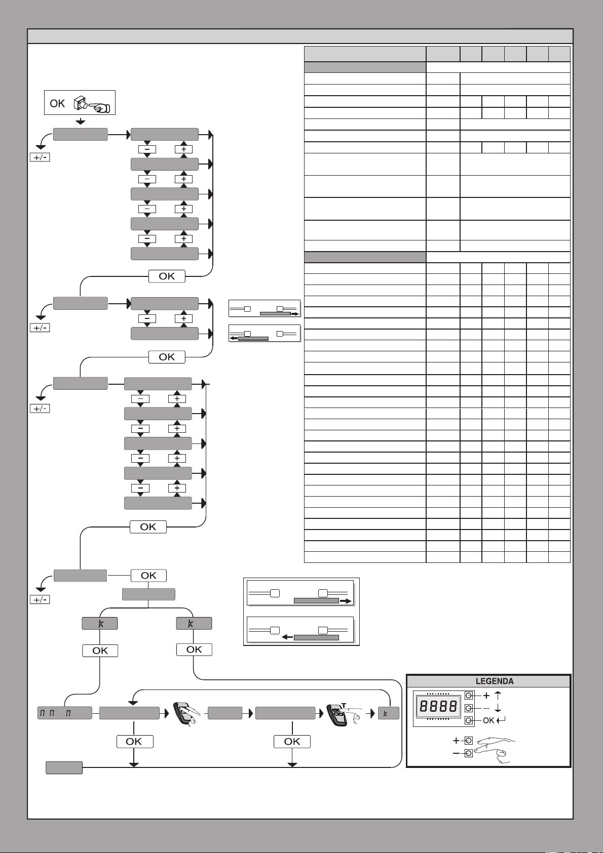
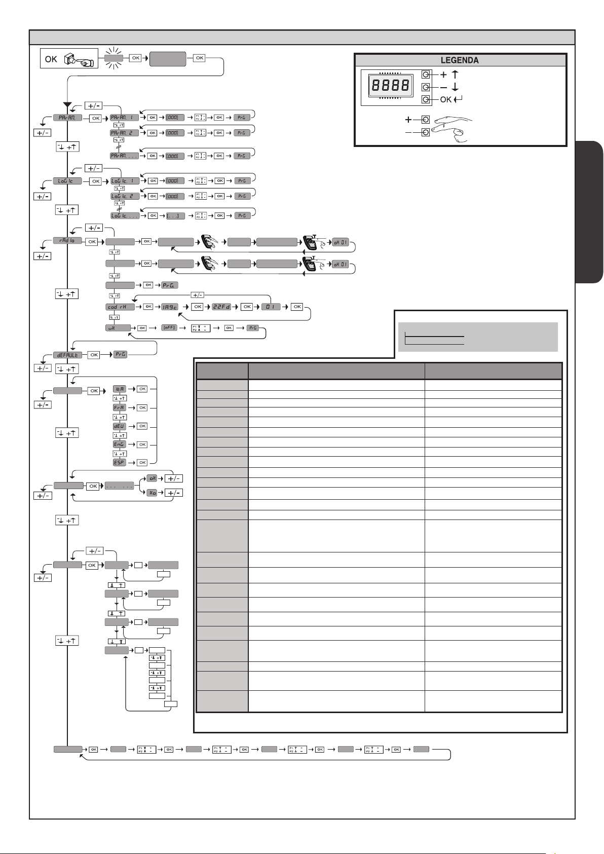
ACCESS MENUS Fig. 1
Scroll up
Scroll down
Conrm/Switch on display
language
**
autoset
stat
add. start
Add. 2ch
erase 64
vers
-
+
n. cycles
-
+
n. remotes
-
+
err
hidden butt
hidden butt
Control unit
software version
OK
bft . . .
+/-
No total
manoeuvres(in hundreds)
OK
0000
+/-
No radio control
devices memorised
OK
00
+/-
List of last 30 errors
OK
01.33
02.01
........
30.15
+/-
See PARAMETERS MENU
See LOGIC MENU
release
desired button
release
desired button
See RADIO MENU
Diagnostics
code
STRE
STRI
OPEN
CLS
PED
TIME
STOP
PHOT
PHOP
PHCL
BAR
BAR 2
SWC
SWO
SET
ER01
ER02
ER03
ER04
ER05
er06
ER1x*
ER3x*
ER5x*
ER7x*
*X= 0, 1, .., 9, A, B, C, D, E, F
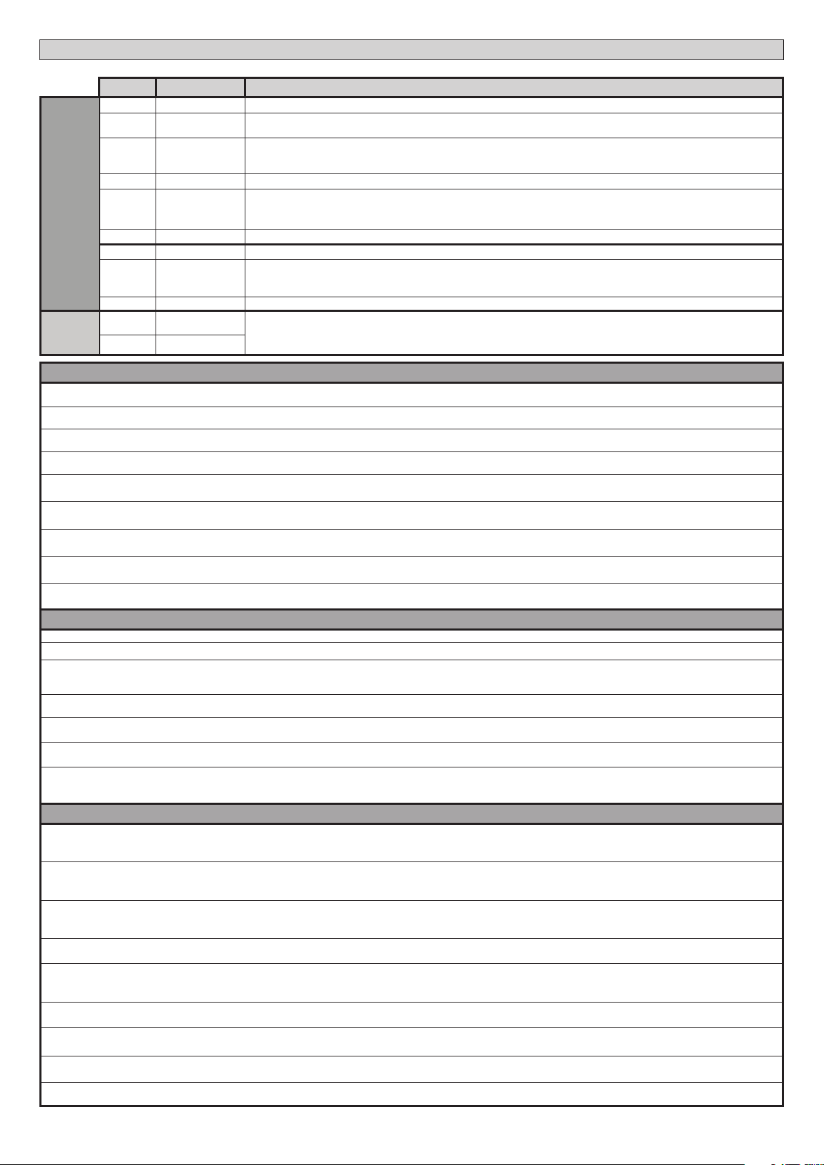
START E external start input activated
START I internal start input activated
OPEN input activated
CLOSE input activated
PED pedestrian input activated
TIMER input activated
STOP input activated
PHOT photocell input activated
PHOT OP opening photocell input activated
PHOT CL closing photocell input activated
BAR safety edge input activated
BAR safety edge input activated on slave motor
(opposite leaves connection)
SWC motor closing limit switch input activated
SWO motor opening limit switch input activated
The board is standing by to perform a complete openingclosing cycle uninterrupted by intermediate stops in
order to acquire the torque required for movement.
WARNING! Obstacle detection not active
Photocell test failed
Safety edge test failed
Opening photocell test failed
Closing photocell test failed
Safety edge test on slave motor failed (opposite leaves
connection)
8k2 safety edge test failed
Board hardware test error
Reverse due to obstacle - Amperostop Check for obstacles in path
Communication error with remote devices
Internal system supervision control error.
DESCRIPTION NOTES
Exit Menù
35.40
Check photocell connection and/or logic settings
Check safety edge connection and/or logic settings
Check photocell connection and/or param-
eter/logic setting
Check photocell connection and/or parameter/logic setting
Check safety edge connection and/or parameter/logic settings
Check safety edge connection and/or parameter/logic settings
- Check connections to motor
- Hardware problems with board (contact
technical assistance)
Check connection with serial-connected
accessory devices and/or expansion boards
Try switching the board o and back on again.
If the problem persists, contact the technical
assistance department.
Obstacle threshold
Instantaneous force motor
ENGLISH
**
password
**
Only active on LEO B CBB 3 230 L02
0---
10--
150- 1520 prg
LEO B CBB 3 230 L02/L04 - LEO B CBB 3 120 F02 / F04 - 21
Page 8

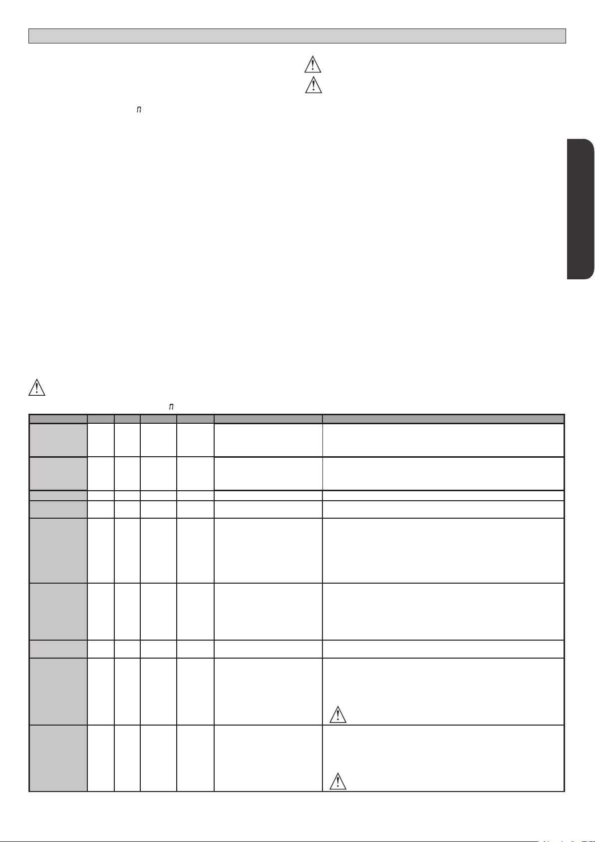
INSTALLER WARNINGS
WARNING! Important safety instructions. Carefully read and comply with
all the warnings and instructions that come with the product as incorrect
installation can cause injury to people and animals and damage to property.
The warnings and instructions give important information regarding safety,
installation, use and maintenance. Keep hold of instructions so that you can
attach them to the technical le and keep them handy for future reference.
GENERAL SAFETY
This product has been designed and built solely for the purpose indicated herein.
Uses other than those indicated herein might cause damage to the product and
create a hazard.
- The units making up the machine and its installation must meet the requirements
of the following European Directives, where applicable: 2004/108/EC, 2006/95/
EC, 2006/42/EC, 89/106/EC, 99/05/EC and later amendments. For all countries
outside the EEC, it is advisable to comply with the standards mentioned, in addition to any national standards in force, to achieve a good level of safety.
- The Manufacturer of this product (hereinafter referred to as the “Firm”) disclaims
all responsibility resulting from improper use or any use other than that for
which the product has been designed, as indicated herein, as well as for failure
to apply Good Practice in the construction of entry systems (doors, gates, etc.)
and for deformation that could occur during use.
- Installation must be carried out by qualied personnel (professional installer,
according to EN 12635), in compliance with Good Practice and current code.
- Before installing the product, make all structural changes required to produce
safety gaps and to provide protection from or isolate all crushing, shearing and
dragging hazard areas and danger zones in general in accordance with the
provisions of standards EN 12604 and 12453 or any local installation standards.
Check that the existing structure meets the necessary strength and stability
requirements.
- Before commencing installation, check the product for damage.
- The Firm is not responsible for failure to apply Good Practice in the construction
and maintenance of the doors, gates, etc. to be motorized, or for deformation
that might occur during use.
- Make sure the stated temperature range is compatible with the site in which the
automated system is due to be installed.
- Do not install this product in an explosive atmosphere: the presence of ammable
fumes or gas constitutes a serious safety hazard.
- Disconnect the electricity supply before performing any work on the system.
Also disconnect buer batteries, if any are connected.
- Before connecting the power supply, make sure the product’s ratings match the
mains ratings and that a suitable residual current circuit breaker and overcurrent
protection device have been installed upline from the electrical system. Have
the automated system’s mains power supply tted with a switch or omnipolar
thermal-magnetic circuit breaker with a contact separation that meets code
requirements.
- Make sure that upline from the mains power supply there is a residual current
circuit breaker that trips at no more than 0.03A as well as any other equipment
required by code.
- Make sure the earth system has been installed correctly: earth all the metal parts
belonging to the entry system (doors, gates, etc.) and all parts of the system
featuring an earth terminal.
- Installation must be carried out using safety devices and controls that meet
standards EN 12978 and EN 12453.
- Impact forces can be reduced by using deformable edges.
- In the event impact forces exceed the values laid down by the relevant standards,
apply electro-sensitive or pressure-sensitive devices.
- Apply all safety devices (photocells, safety edges, etc.) required to keep the
area free of impact, crushing, dragging and shearing hazards. Bear in mind the
standards and directives in force, Good Practice criteria, intended use, the installation environment, the operating logic of the system and forces generated by
the automated system.
- Apply all signs required by current code to identify hazardous areas (residual
risks). All installations must be visibly identied in compliance with the provisions
of standard EN 13241-1.
- Once installation is complete, apply a nameplate featuring the door/gate’s data.
- This product cannot be installed on leaves incorporating doors (unless the motor
can be activated only when the door is closed).
- If the automated system is installed at a height of less than 2.5 m or is accessible,
the electrical and mechanical parts must be suitably protected.
- Install any xed controls in a position where they will not cause a hazard, away
from moving parts. More specically, hold-to-run controls must be positioned
within direct sight of the part being controlled and, unless they are key operated,
must be installed at a height of at least 1.5 m and in a place where they cannot
be reached by the public.
- Apply at least one warning light (ashing light) in a visible position, and also
attach a Warning sign to the structure.
- Attach a label near the operating device, in a permanent fashion, with information on how to operate the automated system’s manual release.
- Make sure that, during operation, mechanical risks are avoided or relevant
protective measures taken and, more specically, that nothing can be banged,
crushed, caught or cut between the part being operated and surrounding parts.
- Once installation is complete, make sure the motor automation settings are
correct and that the safety and release systems are working properly.
- Only use original spare parts for any maintenance or repair work. The Firm disclaims all responsibility for the correct operation and safety of the automated
system if parts from other manufacturers are used.
- Do not make any modications to the automated system’s components unless
explicitly authorized by the Firm.
- Instruct the system’s user on what residual risks may be encountered, on the
control systems that have been applied and on how to open the system manually in an emergency. give the user guide to the end user.
- Dispose of packaging materials (plastic, cardboard, polystyrene, etc.) in accordance with the provisions of the laws in force. Keep nylon bags and polystyrene
out of reach of children.
WIRING
WARNING! For connection to the mains power supply, use: a multicore cable with
a cross-sectional area of at least 5x1.5mm
phase power supplies or 3x1.5mm
type H05 VV-F cable can be used with a cross-sectional area of 4x1.5mm2). To connect auxiliary equipment, use wires with a cross-sectional area of at least 0.5 mm
- Only use pushbuttons with a capacity of 10A-250V or more.
- Wires must be secured with additional fastening near the terminals (for example,
using cable clamps) in order to keep live parts well separated from safety extra
low voltage parts.
- During installation, the power cable must be stripped to allow the earth wire
to be connected to the relevant terminal, while leaving the live wires as short
as possible. The earth wire must be the last to be pulled taut in the event the
cable’s fastening device comes loose.
WARNING! safety extra low voltage wires must be kept physically separate from
low voltage wires.
Only qualied personnel (professional installer) should be allowed to access
live parts.
CHECKING THE AUTOMATED SYSTEM AND MAINTENANCE
Before the automated system is nally put into operation, and during maintenance
work, perform the following checks meticulously:
- Make sure all components are fastened securely.
- Check starting and stopping operations in the case of manual control.
- Check the logic for normal or personalized operation.
- For sliding gates only: check that the rack and pinion mesh correctly with 2 mm
of play along the full length of the rack; keep the track the gate slides on clean
and free of debris at all times.
- For sliding gates and doors only: make sure the gate’s running track is straight
and horizontal and that the wheels are strong enough to take the weight of the
gate.
- For cantilever sliding gates only: make sure there is no dipping or swinging
during operation.
- For swing gates only: make sure the leaves’ axis of rotation is perfectly vertical.
-For barriers only: before opening the door, the spring must be decompressed
(vertical boom).
- Check that all safety devices (photocells, safety edges, etc.) are working properly
and that the anti-crush safety device is set correctly, making sure that the force
of impact measured at the points provided for by standard EN 12445 is lower
than the value laid down by standard EN 12453.
- Impact forces can be reduced by using deformable edges.
- Make sure that the emergency operation works, where this feature is provided.
- Check opening and closing operations with the control devices applied.
- Check that electrical connections and cabling are intact, making extra sure that
insulating sheaths and cable glands are undamaged.
- While performing maintenance, clean the photocells’ optics.
- When the automated system is out of service for any length of time, activate the
emergency release (see “EMERGENCY OPERATION” section) so that the operated
part is made idle, thus allowing the gate to be opened and closed manually.
-
If the power cord is damaged, it must be replaced by the manufacturer or their
technical assistance department or other such qualied person to avoid any risk .
- If “D” type devices are installed (as dened by EN12453), connect in unveried
mode, foresee mandatory maintenance at least every six months
WARNING!
Remember that the drive is designed to make the gate/door easier to use and
will not solve problems as a result of defective or poorly performed installation
or lack of maintenance
SCRAPPING
Materials must be disposed of in accordance with the regulations in force. There
are no particular hazards or risks involved in scrapping the automated system. For
the purpose of recycling, it is best to separate dismantled parts into like materials
(electrical parts - copper - aluminium - plastic - etc.).
DISMANTLING
If the automated system is being dismantled in order to be reassembled at another
site, you are required to:
- Cut o the power and disconnect the whole electrical system.
- Remove the actuator from the base it is mounted on.
- Remove all the installation’s components.
- See to the replacement of any components that cannot be removed or happen
to be damaged.
THE DECLARATION OF CONFORMITY CAN BE VIEWED ON THIS WEBSITE:
WWW.BFT.IT IN THE PRODUCT SECTION.
2
or 4x1.5mm2 when dealing with three-
2
for single-phase supplies (by way of example,
Anything that is not explicitly provided for in the installation manual is not allowed. The operator’s proper operation can only be
guaranteed if the information given is complied with. The Firm shall
not be answerable for damage caused by failure to comply with the
instructions featured herein.
While we will not alter the product’s essential features, the Firm reserves
the right, at any time, to make those changes deemed opportune to
improve the product from a technical, design or commercial point of
view, and will not be required to update this publication accordingly.
D811893 00100_02
2
.
22 - LEO B CBB 3 230 L02/L04 - LEO B CBB 3 120 F02 / F04
AVVERTENZE PER L’INSTALLATORE D811766_08
Page 9

INSTALLATION MANUAL
2) GENERAL INFORMATION
The LEO B CBB 3 230 L02 - LEO B CBB 3 230 L04 - LEO B CBB 3 120 F02 - LEO B
CBB 3 120 F04 control panel comes with standard factory settings. Any change
must be made using the programmer with built-in display or universal handheld
programmer.
D811893 00100_02
Its main features are:
- Control of 1 single-phase motor
- Electronic torque control
- Obstacle detection (only on LEO B CBB 3 230 L02 e LEO B CBB 3 120 F02)
- Separate inputs for safety devices
- Congurable command inputs
- Built-in radio receiver rolling code with transmitter cloning.
The board has a terminal strip of the removable kind to make maintenance
or replacement easier. It comes with a series of prewired jumpers to make the
installer’s job on site easier.
The jumpers concern terminals: 70-71, 70-72, 70-74, 76-77. If the abovementioned terminals are being used, remove the relevant jumpers.
Power supply
Obstacle
detection with
encoder
Output for
terminals 26-27:
N.O. contact
(24V~/0,5A)
TESTING
The LEO B CBB 3 230 L02 - LEO B CBB 3 230 L04 - LEO B CBB 3 120 F02 - LEO
B CBB 3 120 F04 panel controls (checks) the start relays and safety devices
(photocells) before performing each opening and closing cycle.
If there is a malfunction, make sure that the connected devices are working
properly and check the wiring.
WIRING AND TERMINAL BOARD CONFIGURATION
The Control unit completely supports the EELINK protocol.
LEO B CBB 3
230 L02
230V~ ±10%
50Hz/60Hz
LEO B CBB 3
120 F02
120V~ ±10%
50Hz/60Hz
LEO B CBB 3
230 L04
230V~ ±10%
50Hz/60Hz
LEO B CBB 3
120 F04
120V~ ±10%
50Hz/60Hz
Present Present Not present Not present
AUX3
congurable
Output for
audible signal
AUX3
congurable
AUX3
congurable
3) TECHNICAL SPECIFICATIONS
Power supply
230V~ ±10% 50Hz/60Hz
(LEO B CBB 3 230 L02, LEO B CBB 3 230 L04)
120V~ ±10% 50Hz/60Hz
(LEO B CBB 3 120 F02, LEO B CBB 3 120 F04)
Low voltage/mains insulation > 2MOhm 500V
Operating temperature range -20 / +55°C
Thermal overload protection Built into motor
Dielectric rigidity mains/LV 3750V~ for 1 minute
Maximum motor power 750W
Accessories power supply
24V~ (demand max. 1A)
24V~safe
AUX 3/ Output for audible signal NO contact (24V~/max.0,5A)
Flashing light
Dimensions
230V~ 40W max
146x170x60mm
Fuses see Fig. B
N° of combinations 4 billion
Max.n° of transmitters that can be memorized
63
Usable transmitter versions:
All ROLLING CODE transmitters compatible with
4) TUBE ARRANGEMENT Fi g. A
5) TERMINAL BOARD WIRING Fig. B
WARNINGS - When performing wiring and installation, refer to the standards in
force and, whatever the case, apply good practice principles.
Wires carrying dierent voltages must be kept physically separate from each other,
or they must be suitably insulated with at least 1mm of additional insulation.
Wires must be secured with additional fastening near the terminals, using devices
such as cable clamps.
All connecting cables must be kept far enough away from the dissipater.
ENGLISH
Terminal Denition Description
Power supply
Motor
Aux
switch
Motor 1 limit
Accessories
power supply
Commands
L LINE
N NEUTRAL
GND EARTH
10 START + CAP
11 COM
12 START
13 CAP
20
21
26
27
41 + REF SWE Limit switch common
42 SWC Closing limit switch SWC (N.C.)
43 SWO - Opening limit switch SWO (N.C.)
50 24V-
51 24V+
52 24 Vsafe+
60 Common IC 1 and IC 2 inputs common
61 IC 1
62 IC 2
63 Common IC 3 and IC 4 inputs common
64 IC 3
65 IC 4
LIGHT 230V
FREE
CONTACT (N.O.)
(Max 24V 0,5A)
Single-phase power supply 230V~ ±10%, 50-60Hz, with earth cable
(LEO B CBB 3 230 L02, LEO B CBB 3 230 L04).
Single-phase power supply 120V~ ±10%, 50-60Hz, with earth cable
(LEO B CBB 3 120 F02, LEO B CBB 3 120 F04).
Motor connection.
START + CAP Motor Start and capacitor
COM Motor Common
START MOTOR START
CAP capacitor
Flashing light 230V output max. 40W (LEO B CBB 3 230 L02, LEO B CBB 3 230 L04).
Flashing light 120V output max. 40W (LEO B CBB 3 120 F02, LEO B CBB 3 120 F04).
Contact N.O. (24V~/1A).
“AUX3“ (LEO B CBB 3 230 L02, LEO B CBB 3 230 L04, LEO B CBB 3 120 F04) FIG. B1
Output for acoustic signal (LEO B CBB 3 120 F02) FIG. B2
Accessories power supply output.
Tested safety device power supply output (photocell transmitter and safety edge transmitter).
Output active only during operating cycle.
Congurable command input 1 (N.O.) - Default START E.
START E / START I / OPEN / CLOSE / PED / TIMER / TIMER PED
Refer to the “Command input conguration” table.
Congurable command input 2 (N.O.) - Default PED.
START E / START I / OPEN / CLOSE / PED / TIMER / TIMER PED
Refer to the “Command input conguration” table.
Congurable command input 3 (N.O.) - Default OPEN.
START E / START I / OPEN / CLOSE / PED / TIMER / TIMER PED
Refer to the “Command input conguration” table.
Congurable command input 4 (N.O.) - Default CLOSE.
START E / START I / OPEN / CLOSE / PED / TIMER / TIMER PED
Refer to the “Command input conguration” table.
LEO B CBB 3 230 L02/L04 - LEO B CBB 3 120 F02 / F04 - 23
Page 10
INSTALLATION MANUAL
WIRING AND TERMINAL BOARD CONFIGURATION
Terminal Denition Description
70 Common STOP, SAFE 1 and SAFE 2 inputs common
71 STOP
72 SAFE 1
73 FAULT 1 Test input for safety devices connected to SAFE 1.
74 SAFE 2
Safety devices
Antenna
Aux logic= 0 - 2ND RADIO CHANNEL output.
Contact stays closed for 1s when 2nd radio channel is activated.
Aux logic= 1 - SCA GATE OPEN LIGHToutput.
Contact stays closed during opening and with leaf open, intermittent during closing, open with leaf closed.
Aux logic= 2 - COURTESY LIGHT command output.
Contact stays on for 90 seconds after the last operation.
Aux logic= 3 - ZONE LIGHT command output.
Contact stays closed for the full duration of operation.
Aux logic= 4 - STAIR LIGHT output.
Contact stays closed for 1 second at start of operation.
Aux logic= 5 - GATE OPEN ALARM output.
Contact stays closed if the leaf stays open for double the set TCA time.
Aux logic= 6 - FLASHING LIGHT output.
Contact stays closed while leaves are operating.
Aux logic= 7 - SOLENOID LATCH output.
Contact stays closed for 2 seconds each time gate is opened.
Aux logic= 8 - MAGNETIC LOCK output.
Contact stays closed while gate is closed.
IC logic= 0 - Input congured as Start E. Operation according to STEP-BY-STEP MOV. logic. External start for trac light control.
IC logic= 1 - Input congured as Start I. Operation according to STEP-BY-STEP MOV. logic. Internal start for trac light control.
IC logic= 2 - Input congured as Open.
The command causes the leaves to open. If the input stays closed, the leaves stay open until the contact is opened. When the contact is open, the automated device closes following
the TCA time, where activated.
IC logic= 3 - Input congured as Closed.
The command causes the leaves to close.
IC logic= 4 - Input congured as Ped.
The command causes the leaf to open to the pedestrian (partial) opening position. Operation according to STEP-BY-STEP. logic
IC logic= 5 - Input congured as Timer.
Operation same as open except closing is guaranteed even after a mains power outage.
IC logic= 6 - Input congured as Timer Ped.
The command causes the leaf to open to the pedestrian (partial) opening position. If the input stays closed, the leaf stays open until the contact is opened. If the input stays closed and a Start E,
Start I or Open command is activated, a complete opening-closing cycle is performed before returning to the pedestrian opening position. Closing is guaranteed even after a mains power outage.
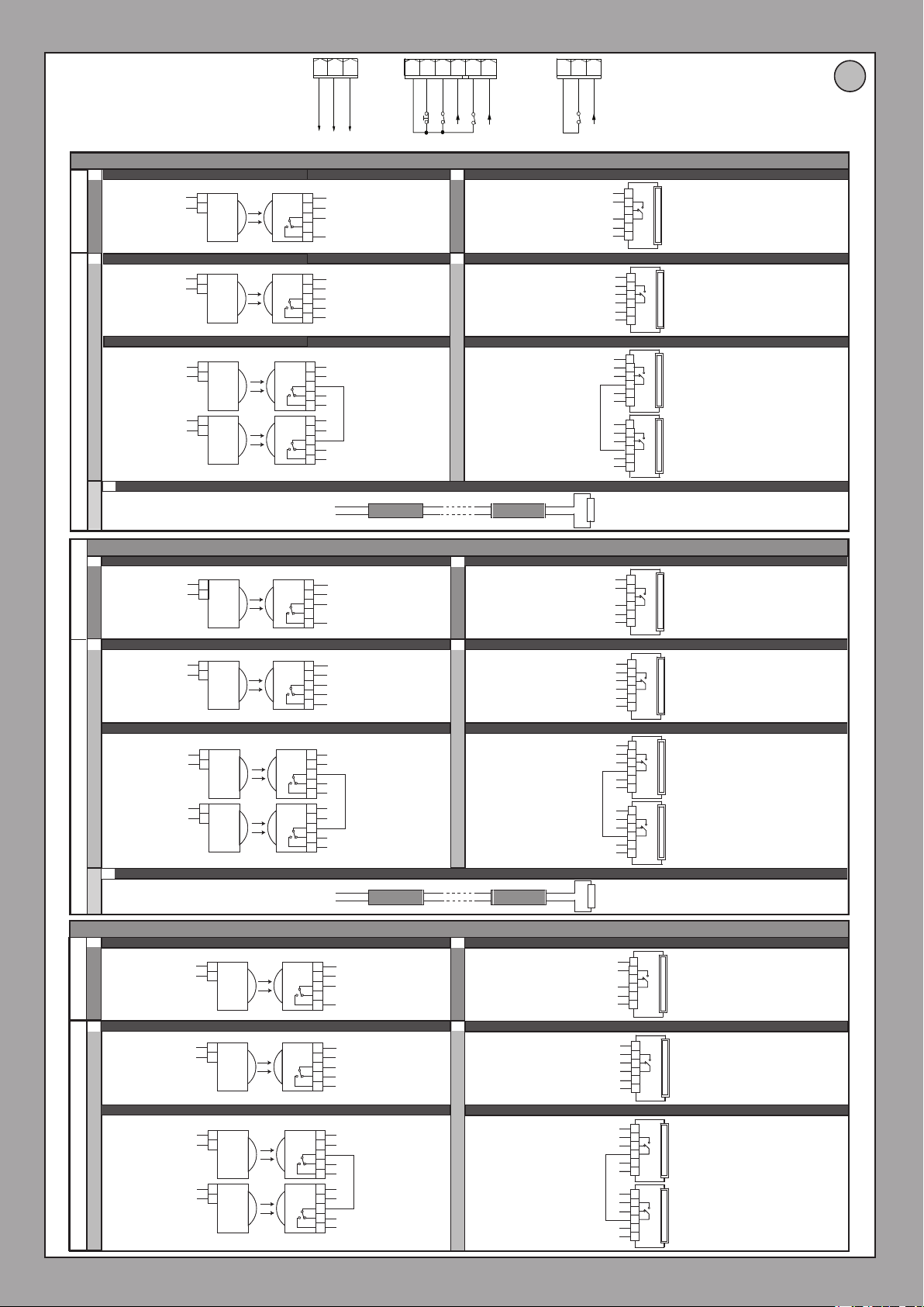
SAFE logic= 0 - Input congured as Phot (photocell) non tested (*) (g.D, ref.1).
Enables connection of devices not equipped with supplementary test contacts. When beam is broken, photocells are active during both opening and closing. When beam is broken
during closing, movement is reversed only once the photocell is cleared. If not used, leave jumper inserted.
SAFE logic= 1 - Input congured as Phot test (tested photocell). (g.D, ref.2).
Switches photocell testing on at start of operation. When beam is broken, photocells are active during both opening and closing. When beam is broken during closing, movement is
reversed only once the photocell is cleared.
SAFE logic= 2 - Input congured as Phot op (photocell active during opening only) non tested (*) (g.D, ref.1).
Enables connection of devices not equipped with supplementary test contacts. In the event beam is broken, photocell operation is disabled during closing. During opening, stops
motion for as long as the photocell beam stays broken. If not used, leave jumper inserted.
SAFE logic= 3 - Input congured as Phot op test (tested photocell active during opening only (gD, ref.2).
Switches photocell testing on at start of operation. In the event beam is broken, photocell operation is disabled during closing. During opening, stops motion for as long as the photocell beam stays broken.
SAFE logic= 4 - Input congured as Phot cl (photocell active during closing only) non tested (*) (g.D, ref.1).
Enables connection of devices not equipped with supplementary test contacts. In the event beam is broken, photocell operation is disabled during opening. During closing, movement is reversed immediately. If not used, leave jumper inserted.
SAFE logic= 5 - Input congured as Phot cl test (tested photocell active during closing only (gD, ref.2).
Switches photocell testing on at start of operation. In the event beam is broken, photocell operation is disabled during opening. During closing, movement is reversed immediately.
SAFE logic= 6 - Input congured as Bar (safety edge) non tested (*) (g.D, ref.3).
Enables connection of devices not equipped with supplementary test contacts. The command reverses movement for 2 sec.. If not used, leave jumper inserted.
SAFE logic= 7 - Input congured as Bar (tested safety edge (g.D, ref.4).
Switches safety edge testing on at start of operation. The command reverses movement for 2 sec.
SAFE logic= 8 - Input congured as Bar 8k2 (g.D, ref.5). Input for resistive edge 8K2.
The command reverses movement for 2 sec..
75 FAULT 2 Test input for safety devices connected to SAFE 2.
76 Common SAFE 3 input common
77 SAFE 3
78 FAULT 3 Test input for safety devices connected to SAFE 3.
Y ANTENNA
# SHIELD
(*) If “D” type devices are installed (as dened by EN12453), connect in unveried mode, foresee mandatory maintenance at least every six months.
24 - LEO B CBB 3 230 L02/L04 - LEO B CBB 3 120 F02 / F04
The command stops movement. (N.C.)
If not used, leave jumper inserted.
Congurable safety input 1 (N.C.) - Default PHOT.
PHOT / PHOT TEST / PHOT OP / PHOT OP TEST / PHOT CL / PHOT CL TEST / BAR / BAR TEST / BAR 8K2
Refer to the “Safety input conguration” table.
Congurable safety input 2 (N.C.) - Default BAR.
PHOT / PHOT TEST / PHOT OP / PHOT OP TEST / PHOT CL / PHOT CL TEST / BAR / BAR TEST / BAR 8K2
Refer to the “Safety input conguration” table.
Congurable safety input 3 (N.C.) - Default PHOT OP.
PHOT / PHOT TEST / PHOT OP / PHOT OP TEST / PHOT CL / PHOT CL TEST / BAR / BAR TEST
Refer to the “Safety input conguration” table.
Antenna input.
Use an antenna tuned to 433MHz. Use RG58 coax cable to connect the Antenna and Receiver. Metal bodies close to the antenna
can interfere with radio reception. If the transmitter’s range is limited, move the antenna to a more suitable position.
AUX output conguration (Not active on LEO B CBB 3 120 F02)
Command input conguration
Safety input conguration
D811893 00100_02
Page 11
INSTALLATION MANUAL
6) SAFETY DEVICES
Note: only use receiving safety devices with free changeover contact.
6.1) TESTED DEVICES Fig. D
6.2 CONNECTION OF 1 PAIR OF NONTESTED PHOTOCELLS FIG. C
D811893 00100_02
7 CALLING UP MENUS: FIG. 1
7.1) PARAMETERS MENU PARA PARAMETERS TABLE “A”
7.2) LOGIC MENU LOGIC LOGIC TABLE “B”
7.3) RADIO MENU radio RADIO TABLE “C”
- IMPORTANT NOTE: THE FIRST TRANSMITTER MEMORIZED MUST BE
IDENTIFIED BY ATTACHING THE KEY LABEL (MASTER).
In the event of manual programming, the rst transmitter assigns the RECEIVER’S
KEY CODE: this code is required to subsequently clone the radio transmitters.
The Clonix built-in on-board receiver also has a number of important advanced features:
• Cloningofmastertransmitter(rollingcodeorxedcode).
• Cloningtoreplacetransmittersalreadyenteredinreceiver.
• Transmitterdatabasemanagement.
• Receivercommunitymanagement.
To use these advanced features, refer to the universal handheld programmer’s
instructions and to the general receiver programming guide.
7.4 DEFAULT MENU default
Restores the controller’s DEFAULT factory settings. Following this reset, you will
need to run the AUTOSET function again.
7.5 LANGUAGE MENU language
Used to set the programmer’s language on the display.
7.6 AUTOSET MENU AUTOset
ONLY ACTIVE ON LEO B CBB 3 230 L02
•
Launch an autoset operation by going to the relevant menu.
•
As soon as you press the OK button, the “.... .... ....” message is displayed and the control
unit commands the device to perform a full cycle (opening followed by closing), dur-
ing which the minimum torque value required to move the leaf is set automatically.
The number of cycles required for the autoset function can range from 1 to 3.
During this stage, it is important to avoid breaking the photocells’ beams and not
to use the START and STOP commands or the display.
Once this operation is complete, the control unit will have automatically set the
optimum force values, slow-down distances and operation times. Check them
and, where necessary, edit them as described in the programming section.
WARNING!! Check that the force of impact measured at the points
provided for by standard EN 12445 is lower than the value laid down
TABLE “A” PARAMETERS MENU - PARA
Parameter min. max. Default
OPEN WORK.T .
CLS WORK.T
TCA
TRF.LGHT.CLR.T
OP.DIST.SLOUD
CL.DIST.
SLOUD
PARTIAL
OPENING
OP.FORCE
CLS.FORCE
(*) In the European Union, apply standard EN 12453 for force limitations, and standard EN 12445 for measuring method.
(**) Impact forces can be reduced by using deformable edges.
5 300 300
5 300 300
0 180 40
1 180 40
0 99 30
0 99 30
10 50 20
(LEO B CBB
3 230 L02)
1 99
(Other
models)
(LEO B CBB
3 230 L02)
1 99
(Other
models)
41
75
41
75
Personal
Denition Description
Opening operation time [s]
Closing operation time [s]
Automatic closing time [s]
Time-to-clear trac light zone [s]
Slow-down distance during
opening [%]
Slow-down distance during
closing [%]
Partial opening [%]
Leaf force during opening
[%]
Leaf force during closing
[%]
by standard EN 12453.
Impact forces can be reduced by using deformable edges.
Warning!! While the autoset function is running, the obstacle detection
function is not active. Consequently, the installer must monitor the
automated system’s movements and keep people and property out
of range of the automated system.
INSTALLATION TEST PROCEDURE
1. Run the AUTOSET cycle (*)
2. Check the impact forces: if they fall within the limits (**) skip to point 10, otherwise
3.
Where necessary, adjust the sensitivity (force) parameters: see parameters table.
4. Check the impact forces again: if they fall within the limits (**) skip to point
10, otherwise
5. Apply a shock absorber prole
6. Check the impact forces again: if they fall within the limits (**) skip to point
10, otherwise
7.
Apply pressure-sensitive or electro-sensitive protective devices (such as a safety edge) (**)
8. Check the impact forces again: if they fall within the limits (**) skip to point
10, otherwise
9. Allow the drive to move only in “Deadman” mode
10. Make sure all devices designed to detect obstacles within the system’s operating
range are working properly
(*) Before running the autoset function, make sure you have performed all the
assembly and make-safe operations correctly, as set out in the installation warnings
in the drive’s manual.
(**) Based on the risk analysis, you may nd it necessary to apply sensitive
protective devices anyway
7.7 STATISTICS MENU
Used to view the version of the board, the total number of operations (in hundreds),
the number of transmitters memorized and the last 30 errors (the rst 2 digits
indicate the position, the last 2 give the error code). Error 01 is the most recent.
7.8) PASSWORD MENU
Used to set a password for the board’s wireless programming.
8) U-LINK OPTIONAL MODULES
Refer to the U-link instructions for the modules.
9) OPPOSITE SLIDING LEAVES FIG. F
Refer to the U-link instructions for the modules.
NOTE: On the board set as the Slave, the Safety Edge input (Safety Edge/ Test Safety
Edge/ 8k2 Safety Edge) should only be set to SAFE2.
Maximum motor operation time, during opening.
Set the operation time so that it’s slightly longer than the complete operating
cycle time. The value is changed by the Autoset cycle, adapting it to the
operation time detected
Maximum motor operation time, during closing.
Set the operation time so that it’s slightly longer than the complete operating
cycle time. The value is changed by the Autoset cycle, adapting it to the
operation time detected
Waiting time before automatic closing.
Time-to-clear for the zone run through by trac controlled by the trac light.
Slow-down distance for motor(s) during opening, given as a percentage
of total travel.
The Autoset cycle changes the slow-down distance values if they don’t
allow at least 50cm of travel at slowed speed.
WARNING: Once the parameter has been edited, a complete
uninterrupted opening-closing cycle is required.
WARNING: when the display reads “SET”, obstacle detection is not
active.
Slow-down distance for motor(s) during closing, given as a percentage of
total travel. The Autoset cycle changes the slow-down distance values if
they don’t allow at least 50cm of travel at slowed speed. WARNING: Once
the parameter has been edited, a complete uninterrupted openingclosing cycle is required.
WARNING: when the display reads “SET”, obstacle detection is not
active.
Partial opening distance as a percentage of total opening following activation of
PED pedestrian command.
Force exerted by leaf/leaves during opening.
Only for LEO B CBB 3 230 L02:
beyond the force stored during the autoset cycle (and subsequently
updated), before an obstacle alarm is generated.
The parameter is set automatically by the autoset function.
WARNING: It aects impact force directly: make sure that
current safety requirements are met with the set value (*).
Install anti-crush safety devices where necessary (**).
Force exerted by leaf/leaves during closing.
Only for LEO B CBB 3 230 L02:
beyond the force stored during the autoset cycle (and subsequently
updated), before an obstacle alarm is generated.
The parameter is set automatically by the autoset function.
WARNING: It aects impact force directly: make sure that
current safety requirements are met with the set value (*).
Install anti-crush safety devices where necessary (**).
This is the percentage of force delivered,
This is the percentage of force delivered,
LEO B CBB 3 230 L02/L04 - LEO B CBB 3 120 F02 / F04 - 25
ENGLISH
Page 12

INSTALLATION MANUAL
Parameter min. max. Default
OP.SLWD.
FORCE
CLS.SLWD.
FORCE
BRAKE
(*) In the European Union, apply standard EN 12453 for force limitations, and standard EN 12445 for measuring method.
(**) Impact forces can be reduced by using deformable edges.
TABELLA “B” LOGICHE LOGIC
Logic Denition
TCA
FAST CLS.
STEP-BY-STEP
MOVEMNT
1 99 75
1 99 75
1 99 0 Braking [%] Percentage of braking applied to stop motion of motor(s).
Automatic Closing
Time
Fast closing 0
Step-by-step
movement
Encoder
(Only active on LEO B
CBB 3 230 L02)
PRE-ALARM
HOLD-TO-RUN
Encoder 2
Pre-alarm 0
Deadman 0
Personal
Default
0
0
Denition Description
“Force exerted by leaf/leaves during opening at slow-down speed.”
Only for LEO B CBB 3 230 L02:
Leaf/leaves force during
opening during
slow-down
Leaf/leaves force during closing
during slow-down [%]
Cross out
setting
used
0 Logic not enabled
1 Switches automatic closing on
0 Logic not enabled
1 Closes 3 seconds after the photocells are cleared before waiting for the set TCA to elapse.
Inputs congured as Start E, Start I,
0
Ped operate with 4-step logic.
Inputs congured as Start E, Start I,
1
Ped operate with 3-step logic. Pulse
during closing reverses movement.
Inputs congured as Start E, Start I,
2
Ped operate with 2-step logic. Movement reverses with each pulse.
Operation with encoder used as position sensor for acquiring slow-down distances. - Gate detection
1
locked out. Manual setting of “opening force”, “closing force”, “opening slow-down force” and “closing
slow-down force” parameters.
Automatic mode with encoder: slow-down and obstacle detection performed by means of encoder.
Option of using “autoset” function. Adjustment of obstacle detection sensitivity (opening force,
closing force, opening slow-down force, closing slow-down force parameters) (default setting).
WARNING: Check that the force of impact measured at the points provided for by standard EN
2
12445 is lower than the value laid down by standard EN 12453.
WARNING: Setting sensitivity incorrectly can result in damage to property and injury to
people and animals.
0 The ashing light comes on at the same time as the motor(s) start.
1 The ashing light comes on approx. 3 seconds before the motor(s) start.
0 Pulse operation.
Deadman mode.
Input 61 is congured as OPEN UP.
Input 62 is congured as CLOSE UP.
1
Operation continues as long as the OPEN UP or CLOSE UP keys are held down.
WARNING: safety devices are not enabled.
Emergency Deadman mode. Usually pulse operation.
If the board fails the safety device tests (photocell or safety edge, Er0x) 3 times in a row, the device is
switched to Deadman mode, which will stay active until the OPEN UP or CLOSE UP keys are released.
2
Input 61 is congured as OPEN UP.
Input 62 is congured as CLOSE UP.
WARNING: with the device set to Emergency Deadman mode, safety devices are not enabled.
beyond the force stored during the autoset cycle (and subsequently
updated), before an obstacle alarm is generated.
The parameter is set automatically by the autoset function.
WARNING: It aects impact force directly: make sure that
current safety requirements are met with the set value (*).
Install anti-crush safety devices where necessary (**).
“Force exerted by leaf/leaves during closing at slow-down speed. “
Only for LEO B CBB 3 230 L02:
beyond the force stored during the autoset cycle (and subsequently
updated), before an obstacle alarm is generated.
The parameter is set automatically by the autoset function.
WARNING: It aects impact force directly: make sure that
current safety requirements are met with the set value (*).
Install anti-crush safety devices where necessary (**).
This is the percentage of force delivered,
This is the percentage of force delivered,
Optional extras
step-by-step mov.
2 STEP 3 STEP 4 STEP
CLOSED
DURING
CLOSING
OPEN
DURING
OPENING
AFTER STOP
OPENS OPENS
CLOSES
OPENS OPENS OPENS
OPENS
STOPS
CLOSES CLOSES
STOP + TCA
STOP + TCA
D811893 00100_02
26 - LEO B CBB 3 230 L02/L04 - LEO B CBB 3 120 F02 / F04
Page 13

INSTALLATION MANUAL
Logic Denition
D811893 00100_02
IBL OPEN
|IBL TCA
IBL CLOSE
OPEN IN OTHER
DIRECT.
SAFE 1
SAFE 2
SAFE 3
IC 1
Default
Block pulses during
opening
Block pulses during
TCA
Block pulses during
closing
Open in other
direction
Conguration of
safety input SAFE 1. 720
Conguration of
safety input SAFE 2. 746
Conguration of
safety input SAFE 3. 772
Conguration of
command input IC 1. 610
0
0
0
0
Cross out
setting
Optional extras
used
0 Pulse from inputs congured as Start E, Start I, Ped has eect during opening.
1 Pulse from inputs congured as Start E, Start I, Ped has no eect during opening.
0 Pulse from inputs congured as Start E, Start I, Ped has eect during TCA pause.
1 Pulse from inputs congured as Start E, Start I, Ped has no eect during TCA pause.
0 Pulse from inputs congured as Start E, Start I, Ped has eect during closing.
1 Pulse from inputs congured as Start E, Start I, Ped has no eect during closing.
0 Standard operating mode (Fig.G Rif. 1).
1 Opens in other direction to standard operating mode (Fig. G Rif.2)
0 Input congured as Phot (photocell).
1 Input congured as Phot test (tested photocell).
2 Input congured as Phot op (photocell active during opening only).
3 Input congured as Phot op test (tested photocell active during opening only).
4 Input congured as Phot cl (photocell active during closing only).
5 Input congured as Phot cl test (tested photocell active during closing only).
6 Input congured as Bar, safety edge.
7 Input congured as Bar, tested safety edge.
8 Input congured as Bar 8k2 (Not active on SAFE 3).
0 Input congured as Start E.
1 Input congured as Start I.
ENGLISH
IC 2
IC 3
IC 4
AUX 3
(Setup for
LEO B CBB 3 120 F02)
FIXED CODE
RADIO PROG
Conguration of
command input IC 2. 624
Conguration of
command input IC 3. 642
Conguration of
command input IC 4. 653 6 Input congured as Timer Pedestrian.
Conguration of
AUX 3 output.
26-37
Fixed code 0
Transmitter pro-
gramming
0
1
2 Input congured as Open.
3 Input congured as Close.
4 Input congured as Ped.
5 Input congured as Timer.
0 Output congured as 2nd Radio Channel.
1 Output congured as SCA (gate open light).
2 Output congured as Courtesy Light command.
3 Output congured as Zone Light command.
4 Output congured as Stair Light
5 Output congured as Alarm
6 Output congured as Flashing light
Receiver is congured for operation in rolling-code mode.
0
Fixed-Code Clones are not accepted.
Receiver is congured for operation in xed-code mode.
1
Fixed-Code Clones are accepted.
Disables wireless memorizing of transmitters.
Transmitters are memorized only using the relevant Radio menu.
0
IMPORTANT: This high level of security stops unwanted clones from gaining access and also
stops radio interference, if any
A- Enables wireless memorizing of transmitters:
Operations in this mode are carried out near the control panel and do not require access:
- Press in sequence the hidden key and normal key (T1-T2-T3-T4) of a transmitter that has already
been memorized in standard mode via the radio menu.
- Press within 10 sec. the hidden key and normal key (T1-T2-T3-T4) of a transmitter to be memorized.
1
The receiver exits programming mode after 10 sec.: you can use this time to enter other new
transmitters by repeating the previous step
B-Enables wireless automatic addition of clones and replays.
Enables clones generated with the universal programmer and programmed replays to be added to
the receiver’s memory.
LEO B CBB 3 230 L02/L04 - LEO B CBB 3 120 F02 / F04
- 27
Page 14

INSTALLATION MANUAL
Logic Denition
SERIAL MODE
ADDRESS
Serial mode
(Identies how board
is congured in a BFT
network connection).
Address 0
Default
0
Cross out
setting
Optional extras
used
0 Standard SLAVE: board receives and communicates commands/diagnostics/etc.
Standard MASTER: board sends activation commands (START, OPEN, CLOSE, PED, STOP) to other
1
boards.
SLAVE opposite leaves in local network : the control unit is the slave in an opposite leaves network
2
with no smart module (g.F)
MASTER opposite leaves in local network: the control unit is the master in an opposite leaves net-
3
work with no smart module (g.F)
[ ___ ]
Identies board address from 0 to 127 in a local BFT network connection.
(see U-LINK OPTIONAL MODULES section)
0 Input congured as Start E command.
1 Input congured as Start I command.
2 Input congured as Open command.
3 Input congured as Close command.
4 Input congured as Ped command.
D811893 00100_02
EXPI1
Conguration of
EXPI1 input on
input-output expan-
sion board.
1-2
1
5 Input congured as Timer command.
6 Input congured as Timer Pedestrian command.
7 Input congured as Phot (photocell) safety.
8 Input congured as Phot op safety (photocell active during opening only).
9 Input congured as Phot cl safety (photocell active during closing only).
10 Input congured as Bar safety (safety edge).
Input congured as Phot test safety (tested photocell).
11
Input 3 (EXPI2) on input/output expansion board is switched automatically to safety device test
input, EXPFAULT1.
Input congured as Phot op test safety (tested photocell active during opening only).
12
Input 3 (EXPI2) on input/output expansion board is switched automatically to safety device test
input, EXPFAULT1.
Input congured as Phot cl test safety (tested photocell active during closing only).
13
Input 3 (EXPI2) on input/output expansion board is switched automatically to
safety device test input, EXPFAULT1.
Input congured as Bar safety (tested safety edge).
14
Input 3 (EXPI2) on input/output expansion board is switched automatically to
safety device test input, EXPFAULT1.
0 Input congured as Start E command.
1 Input congured as Start I command.
2 Input congured as Open command.
Conguration of
EXPI2 input
EXPI2
on input-output
expansion board.
1-3
28 - LEO B CBB 3 230 L02/L04 - LEO B CBB 3 120 F02 / F04
3 Input congured as Close command.
4 Input congured as Ped command.
0
5 Input congured as Timer command.
6 Input congured as Timer Pedestrian command.
7 Input congured as Phot (photocell) safety.
8 Input congured as Phot op safety (photocell active during opening only).
9 Input congured as Phot cl safety (photocell active during closing only).
10 Input congured as Bar safety (safety edge).
Page 15
INSTALLATION MANUAL
Logic Denition
D811893 00100_02
EXPO1
EXPO2
TRAFFIC LIGHT
PREFLASHING
Conguration of
EXPO2 output
on input-output
expansion board
4-5
Conguration of
EXPO2 output
on input-output
expansion board
6-7
Trac light pre-
ashing
Default
9
9
0
Cross out
setting
used
0 Output congured as 2
1 Output congured as SCA (gate open light).
2 Output congured as Courtesy Light command.
3 Output congured as Zone Light command.
4 Output congured as Stair Light.
5 Output congured as Alarm.
6 Output congured as Flashing light.
7 Output congured as Latch.
8 Output congured as Magnetic lock.
9 Output congured as Trac Light control with TLB board.
0 Pre-ashing switched o.
1 Red lights ash, for 3 seconds, at start of operation.
nd
Radio Channel.
Optional extras
ENGLISH
TRAFFIC LIGHT
RED LAMP
Steadily lit red light 0
ALWAYS ON
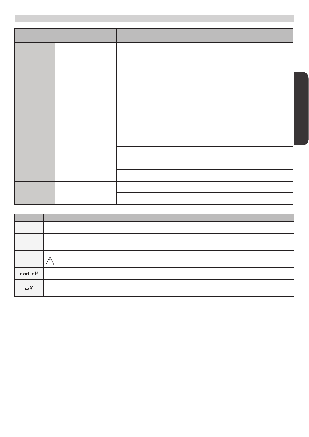
TABLE “C” RADIO MENU RADIO
Logic Description
Add start
add 2ch
erase 64
Add Start Key
associates the desired key with the Start command
Add 2ch Key
associates the desired key with the 2nd radio channel command. Associates the desired key with the 2nd radio channel command. If no output
is congured as 2nd Radio Channel Output, the 2nd radio channel controls the pedestrian opening.
Erase List
WARNING! Erases all memorized transmitters from the receiver’s memory.
Read receiver code
Displays receiver code required for cloning transmitters.
ON = Enables remote programming of cards via a previously memorized W LINK transmitter.
It remains enabled for 3 minutes from the time the W LINK transmitter is last pressed.
OFF= W LINK programming disabled.
0 Red lights o when gate closed.
1 Red lights on when gate closed.
LEO B CBB 3 230 L02/L04 - LEO B CBB 3 120 F02 / F04 - 29
Page 16

D811893 00100_02
Bft Spa
Via Lago di Vico, 44
36015 Schio (VI)
T +39 0445 69 65 11
F +39 0445 69 65 22
www.bft.it
SPAIN
BFT GROUP ITALIBERICA DE
AUTOMATISMOS S.L.
08401 Granollers - (Barcelona)
www.bftautomatismos.com
FRANCE
AUTOMATISMES BFT FRANCE
69800 Saint Priest
www.bft-france.com
GERMANY
BFT TORANTRIEBSSYSTEME Gmb H
90522 Oberasbach
www.bft-torantriebe.de
UNITED KINGDOM
BFT AUTOMATION UK LTD
Stockport, Cheshire, SK7 5DA
www.bft.co.uk
68 - LEO B CBB 3 230 L02/L04 - LEO B CBB 3 120 F02 / F04
IRELAND
BFT AUTOMATION LTD
Dublin 12
BENELUX
BFT BENELUX SA
1400 Nivelles
www.bftbenelux.be
POLAND
BFT POLSKA SP. Z O.O.
05-091 ZąBKI
www.bft.pl
CROATIA
BFT ADRIA D.O.O.
51218 Drazice (Rijeka)
www.bft.hr
PORTUGAL
BFT SA-COMERCIO DE
AUTOMATISMOS E MATERIAL DE
SEGURANCIA
3020-305 Coimbra
www.bftportugal.com
CZECH REPUBLIC
BFT CZ S.R.O.
Praha
www.bft.it
TURKEY
BFT OTOMATIK KAPI SISTEMELERI
SANAY VE
Istanbul
www.bftotomasyon.com.tr
RUSSIA
BFT RUSSIA
111020 Moscow
www.bftrus.ru
AUSTRALIA
BFT AUTOMATION AUSTRALIA
PTY LTD
Wetherill Park (Sydney)
www.bftaustralia.com.au
U.S.A.
BFT USA
Boca Raton
www.bft-usa.com
CHINA
BFT CHINA
Shanghai 200072
www.bft-china.cn
UAE
BFT Middle East FZCO
Dubai
 Loading...