

Page 1
INTRIC 1-2
TRC 1-2-4
MITTO 2-4
433.92 Mhz
D811249 20-10-01 Vers. 06
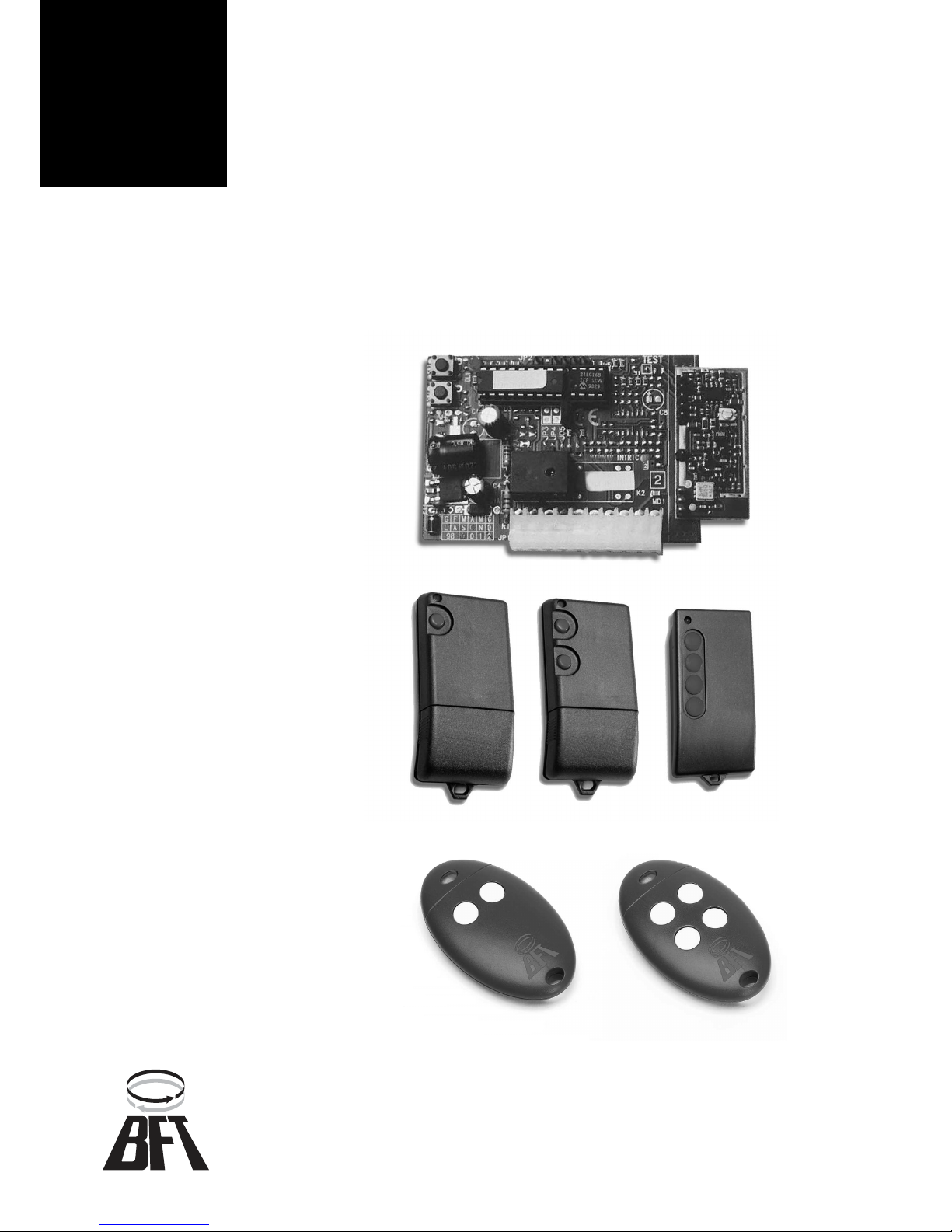
SELF-LEARNING
ROLLING-CODE
RADIO CONTROLS
433.92 MHZ
FREQUENCY
Page 2

353
D811249_06
RADIO CONTROLS
RADIO CONTROLS
INTRIC 1-2/TRC 1-2-4/MITTO 2-4 433.92 MHZ
INTRIC 1-2/TRC 1-2-4/MITTO 2-4 433.92 MHZ
1) GENERAL OUTLINE
Thank you for buying this product, our company is sure that you will be more
than satisfied with the performance of the product. Read the “Instruction
Manual” supplied with this product carefully, as it provides important
information about safety, installation, operation and maintenance.This
product conforms to recognised technical standards and safety regulations.
It complies with the 89/336/EEC, 1999/5/CEE, European Directive and
subsequent amendments. This product complies with recognised technical
standards and safety regulations. Self-learning rolling-code radio receiver
system. This is used to configure impulse or bistable or timed outputs. It can
also memorize TEO 1-2-4 series (non rolling-code) transmitters. The
INTRIC/TRC-MITTO system is compatible with the EElink protocol for fast
installation and maintenance.
2) GENERAL SAFETY
WARNING! An incorrect installation or improper use of the product
can cause damage to persons, animals or things.
• The “Warnings” leaflet and “Instruction booklet” supplied with this
product should be read carefully as they provide important information
about safety, installation, use and maintenance.
• Scrap packing materials (plastic, cardboard, polystyrene etc) according
to the provisions set out by current standards. Keep nylon or polystyrene
bags out of children’s reach.
• Keep the instructions together with the technical brochure for future
reference.
• This product was exclusively designed and manufactured for the use
specified in the present documentation. Any other use not specified in
this documentation could damage the product and be dangerous.
• The Company declines all responsibility for any consequences resulting
from improper use of the product, or use which is different from that
expected and specified in the present documentation.
• Do not install the product in explosive atmosphere.
• The construction components of this product must comply with the
following European Directives:It complies with the 89/336/EEC, 1999/
5/CEE, European Directive and subsequent amendments. As for all
non-EEC countries, the above-mentioned standards as well as the
current national standards should be respected in order to achieve a
good safety level.
• The Company declines all responsibility for any consequences resulting
from failure to observe Good Technical Practice when constructing
closing structures (door, gates etc.), as well as from any deformation
which might occur during use.
• The installation must comply with the provisions set out by the following
European Directives:It complies with the 89/336/EEC, 1999/5/CEE,
European Directive and subsequent amendments.
• Disconnect the electrical power supply before carrying out any work on
the installation. Also disconnect any buffer batteries, if fitted.
• Fit an omnipolar or magnetothermal switch on the mains power supply,
having a contact opening distance equal to or greater than 3mm.
• Check that a differential switch with a 0.03A threshold is fitted just
before the power supply mains.
• Check that earthing is carried out correctly: connect all metal parts for
closure (doors, gates etc.) and all system components provided with an
earth terminal.
• Fit all the safety devices (photocells, electric edges etc.) which are
needed to protect the area from any danger caused by squashing,
conveying and shearing.
• Position at least one luminous signal indication device (blinker) where
it can be easily seen, and fix a Warning sign to the structure.
• The Company declines all responsibility with respect to the automation safety
and correct operation when other manufacturers’ components are used.
• Only use original parts for any maintenance or repair operation.
• Do not modify the automation components, unless explicitly authorised
by the company.
• Instruct the product user about the control systems provided and the
manual opening operation in case of emergency.
• Do not allow persons or children to remain in the automation
operation area.
• Keep radio control or other control devices out of children’s reach, in
order to avoid unintentional automation activation.
• The user must avoid any attempt to carry out work or repair on the
automation system, and always request the assistance of qualified
personnel.
• Anything which is not expressly provided for in the present instructions,
is not allowed.
3) TECHNICAL SPECIFICATIONS
Frequency: .............................................................................. 433.92MHz
Operating temperature: .......................................................... -20 / +55°C
Coded by means of: .............................................. Rolling-code Algorithm
No. combinations: ........................................................................ 4 million
Dimensions: ................................................................................. see fig.1
3.1) Receiver
Power supply: .................................. from 12 to 28Vdc, from 16 to 28Vac
Antenna impedance: ........................................................ 50Ohm (RG58)
Relay contact: ........................................................ 1A - 33Vac, 1A 24Vdc
Max No. radio control to be memorised: ............................................ 128
Receiver versions: INTRIC1 -single-channel, INTRIC2 - double-channel.
3.2) Transmitter MITTO
Keys: ............................................................................................... Yellow
Power supply: ............................. Two 3V lithium batteries (type CR2016)
Range: ............................................................................. 50 / 100 metres
Transmitter versions: MITTO2 - double-channel, MITTO4 - four-channel.
3.3) Transmitter TRC
Keys: ................................................................................................... Red
Power supply: ........................................................... 12V Alkaline battery
Range: ............................................................................. 50 / 100 metres
Transmitter versions:TRC1-single-channel, TRC2-double-channel, TRC4-four-channel.
4) ANTENNA INSTALLATION
Use an antenna tuned to 433MHz. For Antenna-Receiver connection, use
an RG58 coaxial cable. The presence of metallic masses close by the
antenna can interfere with radio reception. In case of poor transmitting
range, move the antenna to a more suitable site.
5) PROGRAMMING
The receivers are provided with a “JP5” jumper (fig.2) which is used to
enable the transmitters to be memorized, in MANUAL or SELF-LEARNING
mode by radio. Having inserted the receiver in the connector provided with
the control unit, enter the programming mode by pressing the SW1 button
for INTRIC 1 or, in case of INTRIC 2, the SW1 button for the CH1 output and
SW2 button for CH2 output. This condition is signalled by constant blinking
of the DL1 LED. The DL1 LED blinker packs (fig.2), which range from 1 to
6 blinks interrupted by a pause of about 1 second, indicate the different
learning functions (see table). The receiver comes out of the programming
mode if no operations take place during the subsequent 90 seconds.
5.1) Transmitter memory storage in manual mode (JP5 closed)
Select the required function from the table. When the operating method has
been understood, proceed as follows:
a) Preset the receiver to the required function (see table) and check the
DL1 LED blinker packs.
b) Send the transmitter secret code. In the case of TRC1-2/MITTO2-4,
press the P1 hidden button (fig.2). In the case of TRC4, the P1 button
function corresponds to pressing the 4 transmitter buttons simultaneously
or, after opening the battery compartment, bridging the two P1 points with
a screwdriver (fig.2).
Note: For the TEO 1-2-4 series, enter the personal code with the 10-way
Dip-switch provided with the transmitter and press the T key of the
transmitter which is to be memorised.
c) Press the T key of the transmitter which is to be memorised. The key of
that transmitter is now stored.
d) To memorise other transmitters, repeat the sequence from point (b)
within a maximum time of about 10 seconds, otherwise the receiver will
come out of the programming mode.
5.2) Transmitter memory storage in self-learning mode by radio (JP5 open)
This procedure permits to copy the keys of a transmitter previously stored
to a receiver without having to operate on the receiver inside the box.
NOTE: The transmitters belonging to the TEO 1-2-4 series (without
rolling-code) can only be stored MANUALLY.
The first transmitter must be memorized in manual mode (see paragraph
5.1). Note: with JP5 open, you can also carry out memory storage in manual
mode. Leaving the JP5 bridge open, and having a MITTO transmitter
already memorized in the receiver, you can also memorize other transmitters
by radio, as explained below:
a) Send the secret code of the transmitter already memorised. In the case
of TRC1-2/MITTO2-4 transmitters, press the hidden P1 button (fig.2). In the
case of TRC4, the P1 button function corresponds to pressing the 4
transmitter buttons simultaneously or, after opening the battery compartment,
bridging the two P1 points with a screwdriver (fig.2).
b) Press the T key which is also to be assigned to the new transmitter.
c) Transmit the secret code of the new transmitter to be memorized.
d) Press the T key which is to be assigned to the new transmitter.
e) To memorise another transmitter, repeat the sequence from step (c)
N° radio control
Receiver versions
Intric
Intric 512
Intric 2048
128
512
2048
Page 3
354
D811249_06
within a maximum time of 10-15 seconds, otherwise the receiver will come
out of the programming mode.
f) To copy another key, repeat the sequence from step (a) and wait for the receiver to
come out of the programming mode (or disconnect the receiver from the power supply).
Note: Maximum protection from memory storage of foreign codes is
obtained by presetting the JP5 jumper closed and programming in
MANUAL mode or by means of the UNIPRO mod. programmer.
5.3) UNIPRO mod. Universal programmer (Fig.4-Fig.5)
To use the programmer, see the respective instructions. Transmitter -
Connect the UNIPRO programmer to the transmitter by means of the
UNITRC/UNIMITTO and UNIFLAT accessories supplied. Receiver Connect the UNIPRO programmer to the INTRIC receiver by means of the
UNIDA and UNIFLAT accessories supplied. The system will not support
the power input of the UNIPRO programer.
6) MAINTENANCE
The maintenance of the system should only be carried out by qualified
personnel regularly. The MITTO transmitters are supplied by two 3V
lithium battiers (type CR2016).The TRC transmitters are powered by a 12V
alkaline battery.When replacing the batteries type CR2016 do not touch the
poles with thehands.
Any reduction in the transmitter capacity may be due to the batteries getting
flat. When the led of the transmitter flashes, it means that the batteries are
flat and must be replaced.
7) DISPOSAL
ATTENTION: disposal should only be carried out by qualified personnel.
Materials must be disposed of in conformity with the current regulations.
In case of disposal, the system components do not entail any particular
risks or danger. In case of recovered materials, these should be sorted out
by type (electrical components, copper, aluminium, plastic etc.).
For battery disposal, refer to the current regulations.
The descriptions and illustrations contained in the present manual
are not binding. The Company reserves the right to make any
alterations deemed appropriate for the technical, manufacturing
and commercial improvement of the product, while leaving its
essential features unchanged, at any time and without undertaking
to update the present publication.
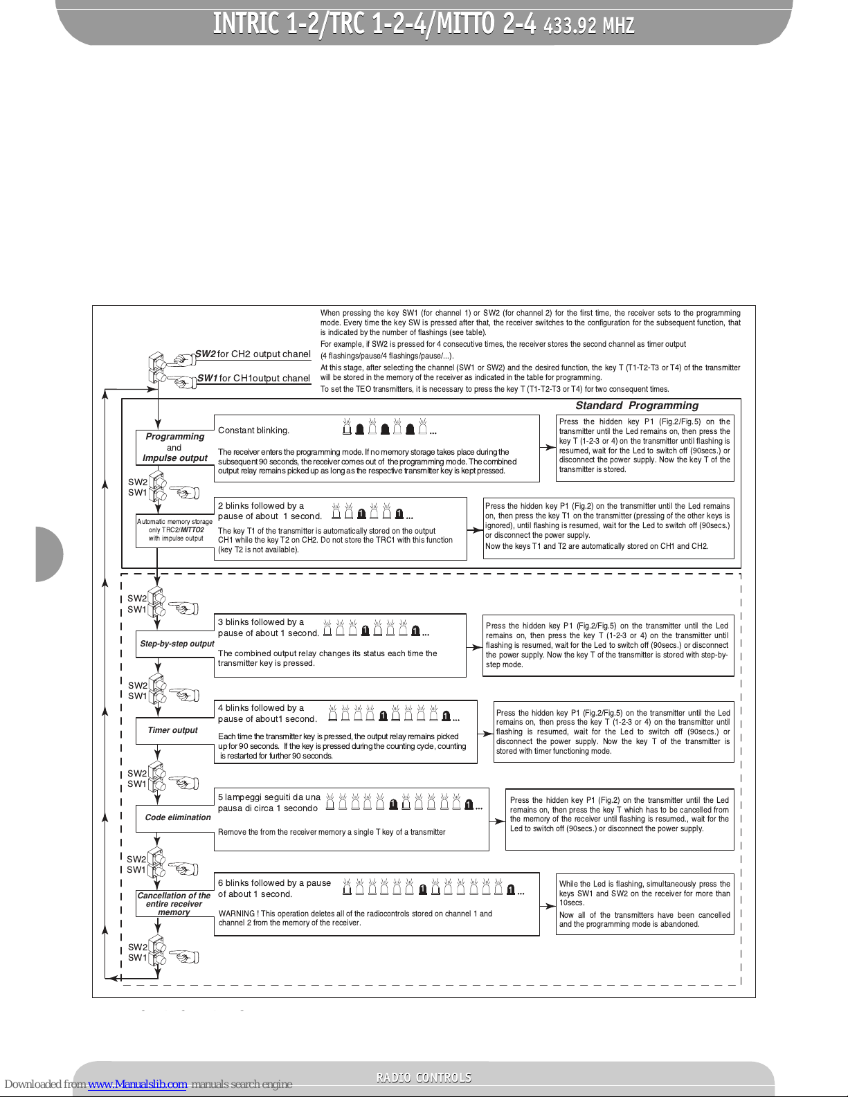
Advanced Programming
When pressing the key SW1 (for channel 1) or SW2 (for channel 2) for the first time, the receiver sets to the programming
mode. Every time the key SW is pressed after that, the receiver switches to the configuration for the subsequent function, that
is indicated by the number of flashings (see table).
For example, if SW2 is pressed for 4 consecutive times, the receiver stores the second channel as timer output
(4 flashings/pause/4 flashings/pause/...).
At this stage, after selecting the channel (SW1 or SW2) and the desired function, the key T (T1-T2-T3 or T4) of the transmitter
will be stored in the memory of the receiver as indicated in the table for programming.
To set the TEO transmitters, it is necessary to press the key T (T1-T2-T3 or T4) for two consequent times.
The receiver enters the programming mode. If no memory storage takes place during the
subsequent 90 seconds, the receiver comes out of the programming mode. The combined
output relay remains picked up as long as the respective transmitter key is kept pressed.
Constant blinking.
Standard Programming
Press the hidden key P1 (Fig.2/Fig.5) on the
transmitter until the Led remains on, then press the
key T (1-2-3 or 4) on the transmitter until flashing is
resumed, wait for the Led to switch off (90secs.) or
disconnect the power supply. Now the key T of the
transmitter is stored.
Press the hidden key P1 (Fig.2) on the transmitter until the Led remains
on, then press the key T1 on the transmitter (pressing of the other keys is
ignored), until flashing is resumed, wait for the Led to switch off (90secs.)
or disconnect the power supply.
Now the keys T1 and T2 are automatically stored on CH1 and CH2.
Press the hidden key P1 (Fig.2/Fig.5) on the transmitter until the Led
remains on, then press the key T (1-2-3 or 4) on the transmitter until
flashing is resumed, wait for the Led to switch off (90secs.) or disconnect
the power supply. Now the key T of the transmitter is stored with step-by-
step mode.
Press the hidden key P1 (Fig.2/Fig.5) on the transmitter until the Led
remains on, then press the key T (1-2-3 or 4) on the transmitter until
flashing is resumed, wait for the Led to switch off (90secs.) or
disconnect the power supply. Now the key T of the transmitter is
stored with timer functioning mode.
Press the hidden key P1 (Fig.2) on the transmitter until the Led
remains on, then press the key T which has to be cancelled from
the memory of the receiver until flashing is resumed., wait for the
Led to switch off (90secs.) or disconnect the power supply.
While the Led is flashing, simultaneously press the
keys SW1 and SW2 on the receiver for more than
10secs.
Now all of the transmitters have been cancelled
and the programming mode is abandoned.
SW2
for CH2 output chanel
SW2
SW1
The combined output relay changes its status each time the
transmitter key is pressed.
3 blinks followed by a
pause of about 1 second.
SW2
SW1
Each time the transmitter key is pressed, the output relay remains picked
up for 90 seconds. If the key is pressed during the counting cycle, counting
is restarted for further 90 seconds.
4 blinks followed by a
pause of about1 second.
SW2
SW1
Remove the from the receiver memory a single T key of a transmitter
5 lampeggi seguiti da una
pausa di circa 1 secondo
SW2
SW1
WARNING ! This operation deletes all of the radiocontrols stored on channel 1 and
channel 2 from the memory of the receiver.
1
1
1
1
1
1
6 blinks followed by a pause
of about 1 second.
SW2
SW1
1
1
SW1
for CH1output chanel
SW2
SW1
2 blinks followed by a
pause of about 1 second.
1
1
The key T1 of the transmitter is automatically stored on the output
CH1 while the key T2 on CH2. Do not store the TRC1 with this function
(key T2 is not available).
Programming
and
Impulse output
Automatic memory storage
only TRC2/
MITTO2
with impulse output
Step-by-step output
Timer output
Code elimination
Cancellation of the
entire receiver
memory
RADIO CONTROLS
RADIO CONTROLS
INTRIC 1-2/TRC 1-2-4/MITTO 2-4 433.92 MHZ
INTRIC 1-2/TRC 1-2-4/MITTO 2-4 433.92 MHZ
Page 4

355
D811249_06
PROGRAMMAZIONE BASE - BASIC PROGRAMMING - PROGRAMMATION DE BASE - BASIS-PROGRAMMIERUNG - PROGRAMACIÓN BASE - PROGRAMAÇÃO BASE
Premere una volta il tasto SW1
Press the key SW1 once
Appuyer une fois sur la touche SW1
Einmal die Taste SW1 drücken.
Presione una vez la tecla SW1
Pressionar uma vez a tecla SW1
1
Premere una volta il tasto SW2
Press the SW2 once
Appuyer une fois sur la touche SW2
Die Taste SW2 einmal drücken.
Presione una vez la tecla SW2
Pressionar uma vez a tecla SW2
6
IL Led comincia a lampeggiare
The Led begins to flash
La led commence clignoter
Die Led beginnt zu blinken.
El led empieza a parpadear
O led começa a piscar
Premere il tasto P1 fino a che il Led del ricevitore resta acceso
Press the key P1 until the Led of the receiver stays on
Appuyer sur la touche P1 jusqu' ce que la Led du rcepteur reste allume
Die Taste P1 drücken, bis die Led des Empfängers eingeschaltet bleibt.
Presione la tecla P1 hasta que el led del receptor se encienda
Pressionar a tecla P1 até que o Led do receptor fica aceso
2
IL Led comincia a lampeggiare
The Led begins to flash
La led commence clignoter
Die Led beginnt zu blinken.
El led empieza a parpadear
O led comea a piscar
7
Attendere che il led si spenga
Wait for the Led to switch off
Attendre que la led s'teint
Warten, bis die Led erlischt.
Espere a que el led se apague
Aguardar que o led se apague
5
3
Premere il tasto P1 fino a che il Led del ricevitore resta acceso
Press the key P1 until the Led of the receiver stays on
Appuyer sur la touche P1 jusqu' ce que la Led du rcepteur reste allume
Die Taste P1 drücken, bis die Led des Empfängers eingeschaltet bleibt.
Presione la tecla P1 hasta que el led del receptor se encienda
Pressionar a tecla P1 até que o Led do receptor fica aceso
8
Premere il tasto T1 fino a che il LED del ricevitore riprende a lampeggiare
Press the key T1 until the Led of the receiver begins to flash again
Appuyer sur la touche T1 jusqu' ce que la LED du rcepteur recommence clignoter
Die Taste T1 drücken, bis die Led des Empfängers wieder zu blinken beginnt.
Presione la tecla T1 hasta que el led del receptor vuelva a parpadear
Pressionar a tecla T1 até que o LED do receptor recomeça a piscar
4
Attendere che il led si spenga
Wait for the Led to switch off
Attendre que la led s'teint
Warten, bis die Led erlischt.
Espere a que el led se apague
Aguardar que o led se apague
10
Premere il tasto T2 fino a che il LED del ricevitore riprende a lampeggiare
Press the key T2 until the Led of the receiver begins to flash again
Appuyer sur la touche T2 jusqu' ce que la LED du rcepteur recommence clignoter
Die Taste T2 drücken, bis die Led des Empfängers wieder zu blinken beginnt.
Presione la tecla T2 hasta que el led del receptor vuelva a parpadear
Pressionar a tecla T2 até que o LED do receptor recomeça a piscar
9
PROGRAMMAZIONE BASE INTRIC2
Uscita impulsiva1e2(per comandare ad esempio lo
start di una centrale di comando e l'apertura pedonale
della stessa)
BASIC PROGRAMMING OF INTRIC2
Impulsive output 1 and 2 (to activate, for example, a
control unit and its
pedestrian opening)
PROGRAMMATION DE BASE INTRIC2
Sortie impulsive 1 et 2 (pour commander par exemple
le start d'une unit de commande et l'ouverture
pitonne de l'unit)
BASIS-PROGRAMMIERUNG INTRIC2
Impuls-Ausgang 1 und 2 (um zum Beispiel den Start
einer Steuerzentrale und deren Fußgängeröffnung zu
befehligen)
PROGRAMACIîN BASE INTRIC2
Salida impulsiva 1 y 2 (para activar, por ejemplo, el
start de una central de mando y la apertura peatonal
de la misma)
PROGRAMAÇÃO BASE INTRIC2
Saída impulsiva 1 e 2 (para comandar por exemplo o
start de uma central de comando e a função abertura
do postigo da mesma)
TRC MITTO
TRC MITTO
TRC MITTO
TRC
MITTO
I
GB
F
D
E
P
RADIO CONTROLS
RADIO CONTROLS
INTRIC 1-2/TRC 1-2-4/MITTO 2-4 433.92 MHZ
INTRIC 1-2/TRC 1-2-4/MITTO 2-4 433.92 MHZ
Page 5

356
D811249_06
Fig. 2
Fig. 1
T1 T2
T3 T4
T1 T2
SW2
DL1
JP5
SW1
75.00
75.00
45.00
16.00
45.00
16.00
MITTO 2
MITTO 4 TRC 1-2 TRC4
P1
Contatti
Contacts
Contacts
Kontakte
Contactos
Contatos
CH1
CH2
+
24vac/12vdc
P1
T1
Led
T2
P1
P1
TRC4
T1
T2
T3
T4
44
18.5
82
T3
T2
T4
T1
16
12.5
65
35
T2
T1
OK!
MITTO 2-4
TRC 1-2
RADIO CONTROLS
RADIO CONTROLS
INTRIC 1-2/TRC 1-2-4/MITTO 2-4 433.92 MHZ
INTRIC 1-2/TRC 1-2-4/MITTO 2-4 433.92 MHZ
Page 6

357
D811249_06
Fig. 3
TEO 4
T4
T4
T3
T3
T2
T2
T1
T1
T1
T1
T2
T2
12V
ALKALINE BATTERY
-
+
ON
10987654321
TEO 2
TRC1-2
TRC4
UNIDA
UNIFLAT
UNITRC
UNITRC
UNIFLAT
UNIPRO
UNIFLAT
Contatti
Contacts
Contacts
Kontakte
Contactos
Contatos
JP2
TRC1-2
INTRIC 1-2
Contatti
Contacts
Contacts
Kontakte
Contactos
Contatos
UNITRC
1
3
4
12
3
4
Fig. 4
TRC 4
RADIO CONTROLS
RADIO CONTROLS
INTRIC 1-2/TRC 1-2-4/MITTO 2-4 433.92 MHZ
INTRIC 1-2/TRC 1-2-4/MITTO 2-4 433.92 MHZ
Page 7

358
D811249_06
Fig. 5
UNIDA
UNIFLAT
UNIMITTO
MITTO 2-4
UNIPRO
UNIFLAT
Contatti
Contacts
Contacts
Kontakte
Contactos
Contatos
JP2
INTRIC 1-2
UNIMITTO
P1
RADIO CONTROLS
RADIO CONTROLS
INTRIC 1-2/TRC 1-2-4/MITTO 2-4 433.92 MHZ
INTRIC 1-2/TRC 1-2-4/MITTO 2-4 433.92 MHZ
 Loading...