


OPERATING INSTRUCTIONS
MCS-D 200
Digital multimedia-based Conference System

Note
This manual is for electro-technically qualified staff. The knowledge and the precise realisation of these instructions are necessary for a smooth installation and security during the operation of the described products.
Due to the danger of fire special installations of power cable may be carried out by electro-technically qualified staff only.
This manual does not include each possible case of installation, operation or maintenance. For more information please contact your beyerdynamic dealer or beyerdynamic GmbH & Co. KG.
beyerdynamic assumes no liability for errors in this documentation and for damages resulting from using this documentation and the products described in it.
Notes for potential reconsignments
1.In order to avoid damages, please dispatch the microphone units in a strong packaging, if you need to return them.
2.If you want to return individual microphone units, please make sure that no heavy weights can damage them or the goosenecks through the packaging.
02

Contents
Table of Contents
1. |
Important Safety Instructions . . . . . . . . . . . . . . . . . . . . . . . . . . . . . . . . . . . . . . . . . . . . . . . . . . . . . . . . . . . . . |
Page |
7 |
|
2. |
Set-up |
. . . . . . . . . . . . . . . . . . . . . . . . . . . . . . . . . . . . . . . . . . . . . . . . . . . . . . . . . . . . . . . . . . . . . . . . . . . . . . . . |
Page |
8 |
3. MCS-D 200 Control Unit . . . . . . . . . . . . . . . . . . . . . . . . . . . . . . . . . . . . . . . . . . . . . . . . . . . . . . . . . . . . . . . . . |
Page |
8 |
||
|
3.1 |
Controls and indicators . . . . . . . . . . . . . . . . . . . . . . . . . . . . . . . . . . . . . . . . . . . . . . . . . . . . . . . . . . . . |
Page |
8 |
|
3.2 |
Putting into operation . . . . . . . . . . . . . . . . . . . . . . . . . . . . . . . . . . . . . . . . . . . . . . . . . . . . . . . . . . . . |
Page |
9 |
|
3.2.1 |
Audio connection . . . . . . . . . . . . . . . . . . . . . . . . . . . . . . . . . . . . . . . . . . . . . . . . . . . . . . . . . . . . . . . . |
Page |
9 |
|
3.2.2 |
Mains connection . . . . . . . . . . . . . . . . . . . . . . . . . . . . . . . . . . . . . . . . . . . . . . . . . . . . . . . . . . . . . . . . |
Page |
10 |
|
3.2.3 |
How to switch the control unit on/off. . . . . . . . . . . . . . . . . . . . . . . . . . . . . . . . . . . . . . . . . . . . . . . . |
Page |
10 |
|
3.2.4 |
How to connect a PC or media control system . . . . . . . . . . . . . . . . . . . . . . . . . . . . . . . . . . . . . . . . . |
Page |
11 |
|
3.2.5 |
Rack mounting . . . . . . . . . . . . . . . . . . . . . . . . . . . . . . . . . . . . . . . . . . . . . . . . . . . . . . . . . . . . . . . . . . |
Page |
11 |
|
3.2.6 |
How to supply the system. . . . . . . . . . . . . . . . . . . . . . . . . . . . . . . . . . . . . . . . . . . . . . . . . . . . . . . . . . |
Page |
11 |
|
3.3 |
How to operate the menu of the MCS-D 200 control unit . . . . . . . . . . . . . . . . . . . . . . . . . . . . . . . |
Page |
12 |
|
3.3.1 |
Menu overview of the MCS-D 200 control unit . . . . . . . . . . . . . . . . . . . . . . . . . . . . . . . . . . . . . . . . |
Page |
12 |
|
3.3.2 |
Main Menu . . . . . . . . . . . . . . . . . . . . . . . . . . . . . . . . . . . . . . . . . . . . . . . . . . . . . . . . . . . . . . . . . . . . . |
Page |
13 |
|
3.3.3 |
System Set-up Menus . . . . . . . . . . . . . . . . . . . . . . . . . . . . . . . . . . . . . . . . . . . . . . . . . . . . . . . . . . . . . |
Page |
14 |
|
3.3.4 |
Session Menus . . . . . . . . . . . . . . . . . . . . . . . . . . . . . . . . . . . . . . . . . . . . . . . . . . . . . . . . . . . . . . . . . . . |
Page |
16 |
|
3.3.4.1 |
Modes / Limit Menus. . . . . . . . . . . . . . . . . . . . . . . . . . . . . . . . . . . . . . . . . . . . . . . . . . . . . . . . . . . . . . |
Page |
17 |
|
3.3.4.2 |
Channel List . . . . . . . . . . . . . . . . . . . . . . . . . . . . . . . . . . . . . . . . . . . . . . . . . . . . . . . . . . . . . . . . . . . . . |
Page |
20 |
|
3.3.4.3 |
President(s). . . . . . . . . . . . . . . . . . . . . . . . . . . . . . . . . . . . . . . . . . . . . . . . . . . . . . . . . . . . . . . . . . . . . . |
Page |
22 |
|
3.3.4.4 |
Interpreter . . . . . . . . . . . . . . . . . . . . . . . . . . . . . . . . . . . . . . . . . . . . . . . . . . . . . . . . . . . . . . . . . . . . . . |
Page |
24 |
|
3.3.5 |
Define Channels . . . . . . . . . . . . . . . . . . . . . . . . . . . . . . . . . . . . . . . . . . . . . . . . . . . . . . . . . . . . . . . . . |
Page |
26 |
|
3.3.6 |
Options. . . . . . . . . . . . . . . . . . . . . . . . . . . . . . . . . . . . . . . . . . . . . . . . . . . . . . . . . . . . . . . . . . . . . . . . . |
Page |
28 |
|
3.3.6.1 |
Time . . . . . . . . . . . . . . . . . . . . . . . . . . . . . . . . . . . . . . . . . . . . . . . . . . . . . . . . . . . . . . . . . . . . . . . . . . . |
Page |
28 |
|
3.3.6.2 |
Ports . . . . . . . . . . . . . . . . . . . . . . . . . . . . . . . . . . . . . . . . . . . . . . . . . . . . . . . . . . . . . . . . . . . . . . . . . . . |
Page |
29 |
|
3.3.6.3 |
MCS-D Info. . . . . . . . . . . . . . . . . . . . . . . . . . . . . . . . . . . . . . . . . . . . . . . . . . . . . . . . . . . . . . . . . . . . . . |
Page |
29 |
|
3.3.7 |
Delegate IDs. . . . . . . . . . . . . . . . . . . . . . . . . . . . . . . . . . . . . . . . . . . . . . . . . . . . . . . . . . . . . . . . . . . . . |
Page |
30 |
|
3.3.7.1 |
ID List . . . . . . . . . . . . . . . . . . . . . . . . . . . . . . . . . . . . . . . . . . . . . . . . . . . . . . . . . . . . . . . . . . . . . . . . . . |
Page |
31 |
|
3.3.7.2 |
Set IDs. . . . . . . . . . . . . . . . . . . . . . . . . . . . . . . . . . . . . . . . . . . . . . . . . . . . . . . . . . . . . . . . . . . . . . . . . . |
Page |
32 |
|
3.3.7.3 |
Conflicts . . . . . . . . . . . . . . . . . . . . . . . . . . . . . . . . . . . . . . . . . . . . . . . . . . . . . . . . . . . . . . . . . . . . . . . . |
Page |
32 |
|
3.3.8 |
Interpreter IDs . . . . . . . . . . . . . . . . . . . . . . . . . . . . . . . . . . . . . . . . . . . . . . . . . . . . . . . . . . . . . . . . . . . |
Page |
33 |
|
3.3.8.1 |
Interpreter ID List . . . . . . . . . . . . . . . . . . . . . . . . . . . . . . . . . . . . . . . . . . . . . . . . . . . . . . . . . . . . . . . . |
Page |
34 |
|
3.3.8.2 |
Set Interpreter IDs . . . . . . . . . . . . . . . . . . . . . . . . . . . . . . . . . . . . . . . . . . . . . . . . . . . . . . . . . . . . . . . . |
Page |
34 |
|
3.3.8.3 |
Conflicts . . . . . . . . . . . . . . . . . . . . . . . . . . . . . . . . . . . . . . . . . . . . . . . . . . . . . . . . . . . . . . . . . . . . . . . . |
Page |
35 |
|
3.3.9 |
Technician IDs . . . . . . . . . . . . . . . . . . . . . . . . . . . . . . . . . . . . . . . . . . . . . . . . . . . . . . . . . . . . . . . . . . . |
Page |
35 |
|
3.3.10 |
DAI/DDI Management. . . . . . . . . . . . . . . . . . . . . . . . . . . . . . . . . . . . . . . . . . . . . . . . . . . . . . . . . . . . . |
Page |
36 |
|
3.3.10.1 Ext. DAI ID List . . . . . . . . . . . . . . . . . . . . . . . . . . . . . . . . . . . . . . . . . . . . . . . . . . . . . . . . . . . . . . . . . . . |
Page |
37 |
|
|
3.3.10.2 DAI Set-up . . . . . . . . . . . . . . . . . . . . . . . . . . . . . . . . . . . . . . . . . . . . . . . . . . . . . . . . . . . . . . . . . . . . . . |
Page |
37 |
|
|
3.3.10.3 DAI Control . . . . . . . . . . . . . . . . . . . . . . . . . . . . . . . . . . . . . . . . . . . . . . . . . . . . . . . . . . . . . . . . . . . . . |
Page |
39 |
|
4. CA 4115/30/45 Power Supply Unit . . . . . . . . . . . . . . . . . . . . . . . . . . . . . . . . . . . . . . . . . . . . . . . . . . . . . . . . . |
Page |
41 |
||
|
4.1 |
Controls and indicators . . . . . . . . . . . . . . . . . . . . . . . . . . . . . . . . . . . . . . . . . . . . . . . . . . . . . . . . . . . . |
Page |
41 |
|
4.2 |
Connection. . . . . . . . . . . . . . . . . . . . . . . . . . . . . . . . . . . . . . . . . . . . . . . . . . . . . . . . . . . . . . . . . . . . . . |
Page |
42 |
|
4.2.1 |
Control unit - power supply unit . . . . . . . . . . . . . . . . . . . . . . . . . . . . . . . . . . . . . . . . . . . . . . . . . . . . |
Page |
42 |
|
4.2.2 |
Microphone stations - power supply unit . . . . . . . . . . . . . . . . . . . . . . . . . . . . . . . . . . . . . . . . . . . . . |
Page |
42 |
|
4.3 |
How to switch on the power supply unit . . . . . . . . . . . . . . . . . . . . . . . . . . . . . . . . . . . . . . . . . . . . . |
Page |
42 |
5. CA 4522/44/66 Digital / Analogue Interface (DAI) . . . . . . . . . . . . . . . . . . . . . . . . . . . . . . . . . . . . . . . . . . . . . |
Page |
43 |
||
|
5.1 |
Controls and Indicators . . . . . . . . . . . . . . . . . . . . . . . . . . . . . . . . . . . . . . . . . . . . . . . . . . . . . . . . . . . . |
Page |
44 |
6. CA 4577 Digital / Digital Interface (DDI) . . . . . . . . . . . . . . . . . . . . . . . . . . . . . . . . . . . . . . . . . . . . . . . . . . . . |
Page |
45 |
||
|
6.1 |
Controls and indicators . . . . . . . . . . . . . . . . . . . . . . . . . . . . . . . . . . . . . . . . . . . . . . . . . . . . . . . . . . . . |
Page |
45 |
7. |
Microphone Stations . . . . . . . . . . . . . . . . . . . . . . . . . . . . . . . . . . . . . . . . . . . . . . . . . . . . . . . . . . . . . . . . . . . . |
Page |
46 |
|
|
7.1 |
MCS-D 2073 . . . . . . . . . . . . . . . . . . . . . . . . . . . . . . . . . . . . . . . . . . . . . . . . . . . . . . . . . . . . . . . . . . . . . |
Page |
46 |
|
7.1.1 |
Controls and indicators . . . . . . . . . . . . . . . . . . . . . . . . . . . . . . . . . . . . . . . . . . . . . . . . . . . . . . . . . . . . |
Page |
46 |
|
7.1.2 |
How to turn the microphone on . . . . . . . . . . . . . . . . . . . . . . . . . . . . . . . . . . . . . . . . . . . . . . . . . . . . |
Page |
48 |
|
7.1.3 |
How to set the volume of the headphone . . . . . . . . . . . . . . . . . . . . . . . . . . . . . . . . . . . . . . . . . . . . |
Page |
49 |
|
7.1.4 |
How to set the language or channel . . . . . . . . . . . . . . . . . . . . . . . . . . . . . . . . . . . . . . . . . . . . . . . . . |
Page |
49 |
|
7.1.5 |
Menu buttons . . . . . . . . . . . . . . . . . . . . . . . . . . . . . . . . . . . . . . . . . . . . . . . . . . . . . . . . . . . . . . . . . . . |
Page |
49 |
|
7.1.6 |
Menu settings . . . . . . . . . . . . . . . . . . . . . . . . . . . . . . . . . . . . . . . . . . . . . . . . . . . . . . . . . . . . . . . . . . . |
Page |
50 |
|
7.1.7 |
How to switch on a microphone while phoning . . . . . . . . . . . . . . . . . . . . . . . . . . . . . . . . . . . . . . . |
Page |
52 |
|
7.1.8 |
How to operate the navigator buttons . . . . . . . . . . . . . . . . . . . . . . . . . . . . . . . . . . . . . . . . . . . . . . . |
Page |
52 |
|
7.1.9 |
Display . . . . . . . . . . . . . . . . . . . . . . . . . . . . . . . . . . . . . . . . . . . . . . . . . . . . . . . . . . . . . . . . . . . . . . . . . |
Page |
52 |
|
7.1.10 |
MCS-D 2073 as chairman station . . . . . . . . . . . . . . . . . . . . . . . . . . . . . . . . . . . . . . . . . . . . . . . . . . . . |
Page |
53 |
|
7.2 |
MCS-D 3121 / 3123 . . . . . . . . . . . . . . . . . . . . . . . . . . . . . . . . . . . . . . . . . . . . . . . . . . . . . . . . . . . . . . . |
Page |
54 |
|
7.2.1 |
Controls and indicators . . . . . . . . . . . . . . . . . . . . . . . . . . . . . . . . . . . . . . . . . . . . . . . . . . . . . . . . . . . . |
Page |
54 |
|
7.2.2 |
How to turn on the MCS-D 3121 . . . . . . . . . . . . . . . . . . . . . . . . . . . . . . . . . . . . . . . . . . . . . . . . . . . . |
Page |
56 |
|
7.2.3 |
How to operate the MCS-D 3123 chairman station . . . . . . . . . . . . . . . . . . . . . . . . . . . . . . . . . . . . . |
Page |
57 |
E 03

04

|
|
|
|
|
Contents |
|
|
|
|
|
|
|
|
|
|
|
|
|
|
|
|
|
7.3 |
MCS-D 3171 / 3173 . . . . . . . . . . . . . . . . . . . . . . . . . . . . . . . . . . . . . . . . . . . . . . . . . . . . . . . . . . . . . . . |
Page |
58 |
|
|
|
7.3.1 |
Controls and indicators . . . . . . . . . . . . . . . . . . . . . . . . . . . . . . . . . . . . . . . . . . . . . . . . . . . . . . . . . . . . |
Page |
58 |
|
|
|
7.3.2 |
How to display the Device ID . . . . . . . . . . . . . . . . . . . . . . . . . . . . . . . . . . . . . . . . . . . . . . . . . . . . . . . |
Page |
59 |
|
|
|
7.3.3 |
How to display messages . . . . . . . . . . . . . . . . . . . . . . . . . . . . . . . . . . . . . . . . . . . . . . . . . . . . . . . . . . |
Page |
60 |
|
|
|
7.3.4 |
How to turn on the MCS-D 3171 . . . . . . . . . . . . . . . . . . . . . . . . . . . . . . . . . . . . . . . . . . . . . . . . . . . . |
Page |
60 |
|
|
|
7.3.5 |
How to adjust the headphone volume . . . . . . . . . . . . . . . . . . . . . . . . . . . . . . . . . . . . . . . . . . . . . . . |
Page |
61 |
|
|
|
7.3.6 |
How to select the language or channel . . . . . . . . . . . . . . . . . . . . . . . . . . . . . . . . . . . . . . . . . . . . . . |
Page |
61 |
|
|
|
7.3.7 |
How to operate the MCS-D 3173 chairman station . . . . . . . . . . . . . . . . . . . . . . . . . . . . . . . . . . . . . |
Page |
61 |
|
|
|
7.4 |
MCS-D 202 . . . . . . . . . . . . . . . . . . . . . . . . . . . . . . . . . . . . . . . . . . . . . . . . . . . . . . . . . . . . . . . . . . . . . . |
Page |
62 |
|
|
|
7.4.1 |
Controls and indicators . . . . . . . . . . . . . . . . . . . . . . . . . . . . . . . . . . . . . . . . . . . . . . . . . . . . . . . . . . . . |
Page |
62 |
|
|
|
7.4.2 |
How to program the relay channel buttons 1-3 . . . . . . . . . . . . . . . . . . . . . . . . . . . . . . . . . . . . . . . . |
Page |
64 |
|
|
|
7.4.3 |
Output channels A and B . . . . . . . . . . . . . . . . . . . . . . . . . . . . . . . . . . . . . . . . . . . . . . . . . . . . . . . . . . |
Page |
65 |
|
|
|
7.4.3.1 |
How to program the output channels A and B . . . . . . . . . . . . . . . . . . . . . . . . . . . . . . . . . . . . . . . . |
Page |
65 |
|
|
|
7.4.4 |
Call buttons . . . . . . . . . . . . . . . . . . . . . . . . . . . . . . . . . . . . . . . . . . . . . . . . . . . . . . . . . . . . . . . . . . . . . |
Page |
66 |
|
|
|
7.4.5 |
How to assign the interpreter ID . . . . . . . . . . . . . . . . . . . . . . . . . . . . . . . . . . . . . . . . . . . . . . . . . . . . |
Page |
68 |
|
|
|
7.4.6 |
How to save settings on a chip card . . . . . . . . . . . . . . . . . . . . . . . . . . . . . . . . . . . . . . . . . . . . . . . . . |
Page |
70 |
|
|
|
7.4.7 |
How to read the chip card data . . . . . . . . . . . . . . . . . . . . . . . . . . . . . . . . . . . . . . . . . . . . . . . . . . . . . |
Page |
70 |
|
|
8. |
Examples . . . . . . . . . . . . . . . . . . . . . . . . . . . . . . . . . . . . . . . . . . . . . . . . . . . . . . . . . . . . . . . . . . . . . . . . . . . . . . |
Page |
72 |
|
|
|
9. |
Components . . . . . . . . . . . . . . . . . . . . . . . . . . . . . . . . . . . . . . . . . . . . . . . . . . . . . . . . . . . . . . . . . . . . . . . . . . . |
Page |
84 |
|
|
|
10. |
Optional Accessories . . . . . . . . . . . . . . . . . . . . . . . . . . . . . . . . . . . . . . . . . . . . . . . . . . . . . . . . . . . . . . . . . . . . |
Page |
84 |
|
|
|
11. |
List of Language Codes . . . . . . . . . . . . . . . . . . . . . . . . . . . . . . . . . . . . . . . . . . . . . . . . . . . . . . . . . . . . . . . . . . |
Page |
85 |
|
|
|
12. |
Technical Specifications . . . . . . . . . . . . . . . . . . . . . . . . . . . . . . . . . . . . . . . . . . . . . . . . . . . . . . . . . . . . . . . . . . |
Page |
87 |
|
|
|
|
|
|
|
|
|
E 05

Introduction
Thank you for selecting the digital multimedia-based MCS-D 200 conference system from beyerdynamic. Please take some time to read carefully through this manual before setting up the equipment.
This manual describes the installation and operation of the MCS-D 200 system without the control and configuration via PC.
MCS-D 200 is a fully digital multimedia-based conference system in single-cable design. It can be used for small and large events in permanent installations or for mobile use.
The system includes the following components:
•MCS-D 200 Control Unit
•MCS-D 2073 Delegate / Chairman Station
•MCS-D 202 Interpreter Stations
•MCS-D 3121 Delegate Station and MCS-D 3123 Chairman Station
•MCS-D 3171 Delegate Station and MCS-D 3173 Chairman Station
•Cabling via “NetRateBus”
The NetRateBus is a special kind of cabling which allows operating all services such as microphone channels, interpreting channels, control, network, telephone and safety precautions simultaneously on 54 channels without any interferences.
The NetRateBus allows different types of cabling such as in a daisy chain, star or tree structure with any branch. The setup is clear and simple.
One conference system can consist of a maximum of 1,400 microphone units.
For the digital interpreter stations there is no additional control unit needed.
Third party devices such as PCs, automatic cameras with pan, tilt, zoom, recording devices, output devices or display screen in the hall can be connected.
With the MultiSession Management several meetings can be controlled simultanously with one control unit and the software. The individual conference rooms can be combined to one large group or conference room by changing the software settings accordingly.
06

Safety Instructions
1. Important Safety Instructions
Control Unit and Power Supply Units
•READ these instructions.
•KEEP these instructions.
•HEED all warnings.
•Follow all instructions.
•Do not use this apparatus near water.
•Clean only with a dry cloth.
•Do not block any ventilation openings. Install in accordance with the manufacturer’s instructions.
•Do not install near any heat sources such as radiators, heat registers, stoves or other apparatus (including amplifiers) that produce heat.
•Do not defeat the safety purpose of the polarised or grounding-type plug. A polarised plug has two blades with one wider than the other. A grounding type plug has two blades and a third grounding prong. The wide blade or the third prong are provided for your safety. If the provided plug does not fit into your outlet, consult an electrician for replacement of the obsolete outlet.
•Protect the power cord from being walked on or pinched particularly at plugs, convenience receptacles, and the point where they exit from the apparatus.
•Only use attachements/accessories specified by the manufacturer.
•Use only with the cart, stand, tripod, bracket or table specified by the manufacturer or sold with the apparatus. When a cart is used, use caution when moving the cart/apparatus combination to avoid injury from tip-over.
•Unplug this apparatus during lightning storms or when unused for long periods of time.
•Refer all servicing to qualified service personnel. Servicing is required when the apparatus has been damaged in any way, such as power-supply cord or plug is damaged, liquid has been spilled or objects have fallen into the apparatus, the apparatus has been exposed to rain or moisture, does not operate normally, or has been dropped.
•The equipment must be set up so that the mains switch, mains plug and all connection on the rear of the device are easily accessible.
•The equipment must be connected to a mains socket that has an earth contact.
•Never expose the equipment to rain or a high level of humidity. For this reason do not install it in the immediate vicinity of swimming pools, showers, damp basement rooms or other areas with unusually high atmospheric humidity.
•Do not use the device/s outside. To reduce the risk of fire or electric shock, do not expose this/these device/s to rain or moisture.
•Never place objects containing liquid (e.g. vases or drinking glasses) on the equipment. Liquids in the equipment could cause a short circuit.
•Lay all connection cables so that they do not present a trip hazard.
•Check whether the connection figures comply with the existing mains supply. Serious damage could occur due to connecting the system to the wrong power supply. An incorrect mains voltage could damage the equipment or cause an electric shock.
•This equipment needs adequate ventilation. Do not cover ventilation grilles. If the heat it generates cannot be dissipated, the equipment could be damaged or flammable materials in its immediate vicinity could be ignited. Take care to ensure that the air can circulate freely through the ventilation grilles and keep flammable materials away.
•Never place naked flames near the equipment.
•If the equipment causes a blown fuse or a short circuit, disconnect it from the mains and have it checked and repaired.
•Do not open the equipment without authorisation. You could receive an electric shock. Leave all service work to authorised expert personnel.
•Do not hold the mains cable with wet hands. There must be no water or dust on the contact pins. In both cases you could receive an electric shock.
•The mains cable must be firmly connected. If it is loose there is a fire hazard.
•Always pull out the mains cable from the mains and/or from the equipment by the plug - never by the cable. The cable could be damaged and cause an electric shock or fire.
•If the power cable is connected, avoid contact of the unit with other metallic objects.
•Do not insert objects into the ventilation grilles or other openings. You could damage the equipment and/or injure yourself.
•Do not use the equipment if the mains plug is damaged.
•When installing the device into a 19" rack, make sure that the mains switch, mains plug and all connection on the rear of the device are easily accessible.
Microphone Units
•Conference microphone stations with metal casings are heavy, so always position them on a secure surface.
•If the microphone stations have a gooseneck microphone take care that you do not injure yourself on this e.g. poke it into your eye
•To align the gooseneck microphone on the microphone station and to avoid twisting it too far and causing premature wear, always grip the microphone by the bottom flexible section never by the microphone head or by the rigid tube. The gooseneck must be bent no further than an angle of 90 ° maximum.
E 77
MCS-D 200 Control Unit
2.Set-up
The MCS-D 200 system may only be installed by staff acquainted with the appropriate safety instructions.
The MCS-D 200 control unit and the power supply units have been developed for installation on tables or 19"-mounting. Do not cover the ventilating grille. When setting up the system please follow the safety instructions mentioned in chapter 1.
Furthermore, please note
•the ambient temperature of the installation site must not exceed 50 °C.
•there must not be exceeding dust and humidity at the installation site.
•that the unit is not exposed to direct sunlight.
•the connections must be protected against direct access during operation.
•that there must be a strain relief of the cables.
•the installation site must be protected against vibrations.
MCS-D 200 Control Unit
MCS-D 200 control unit is the heart of the system. It controls the delegate, chairman and interpreter microphone stations. MCS-D 200 control unit has a modular power supply unit to power a maximum of 15 microphone stations (optional 30). If
than 30 microphone stations are to be used, additional power supply units are necessary to meet the power requirement.
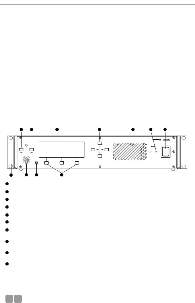
1 Controls and indicators
view
6 |
6 |
7 |
8 |
3 |
2 |
10
LEDs (the number of illuminated LEDs indicates the number of power supply units integrated into the control unit)
Ventilation grille. Do not cover to avoid overheating.
connect microphone or headset (8 pin DIN 45326) - inactive
Headphone socket (3.5 mm) - inactive
|
buttons (left, right) - inactive |
|
with 20 characters / 4 lines. Three lines are used for various menu data. The bottom line is used for the description |
of |
Control Keys. |
Navigator buttons (left, right, up, down). Using the navigator bottoms up / down you can scroll through the menu; using the navigator bottoms left / right you can enter data.
Menu buttons; so-called “hot keys”. Depending on the menu, they act as ENTER, EXIT, VOL-, SETUP, VOL +, SET, LIMIT, button. The description is displayed in the lower line.
10
08

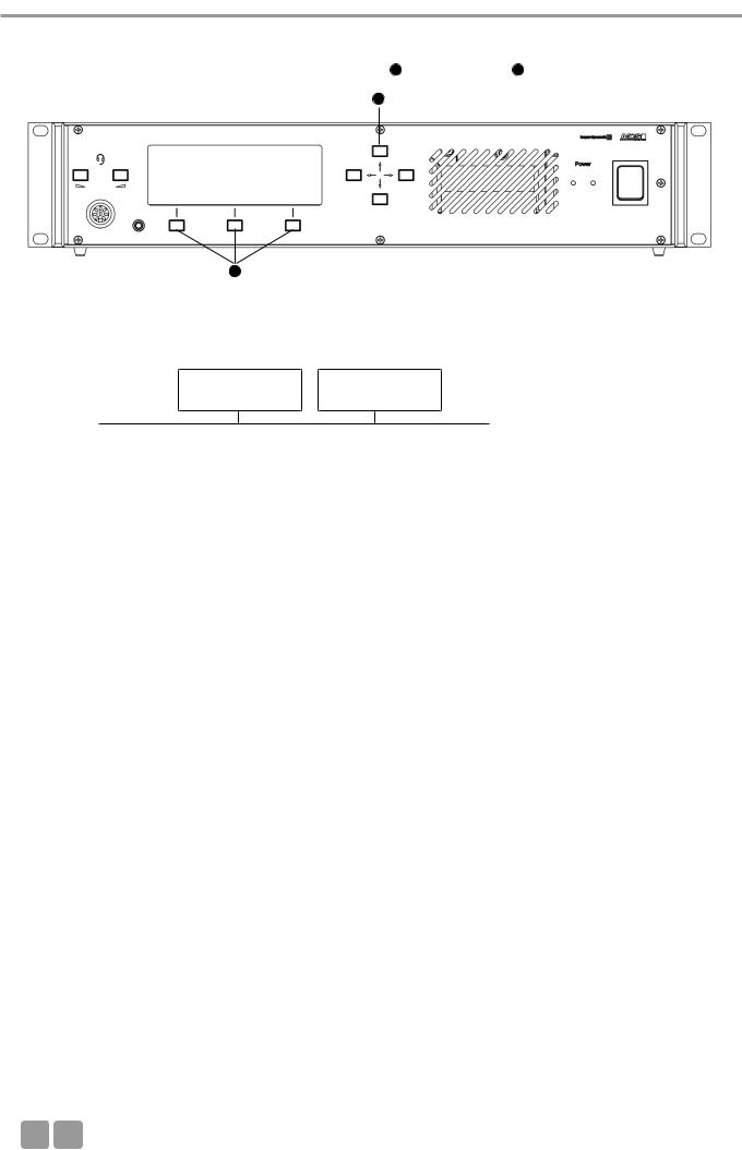
MCS-D 200 Control Units
Rear view
15
20
11
12NetRateBus conference sockets, MCS-D 200 with 1 Push-Pull socket to connect other power supply units for example.
13Fan outlet (number of fan outlets depends on the number of power supply units integrated into the control unit)
14 |
RS 232 C (1). 9-pin |
-D connection for PC or media control system. |
|
|
Note: A PC is connected via a connecting cable (1:1) , no null modem cable. |
|
|
|
If you use other devices, please observe the pin wiring. The configuration is done via the |
unit. |
|
15 |
RS 232 C (2). The |
corresponds to RS 232 C (1). |
|
16 |
CH1 IN: XLR LINE |
input (female), 0 dBm, balanced. The input signal is routed to the loudspeakers of the microphone |
|
|
stations or to any |
. Settings are done via the control unit. |
|
17 |
CH2 IN: XLR LINE |
input (female), 0 dBm, balanced. The input signal is routed to the loudspeakers of the microphone |
|
units or to any output. Settings are done via the control unit.
18CH1 OUT: XLR LINE OUT output (male), 0 dBm, balanced. Master output of all microphones or any channel; programmable for recording or broadcasting applications.
19CH2 OUT: XLR LINE OUT output (male), 0 dBm, balanced. Master output of all microphones or any channel; programmable for recording or broadcasting applications..
20End profile
more inputs and |
connect a CA 45xx D/A Interface. |
3.2 Putting into operation
3.2.1Audio connection
• |
Connect the master output 18 |
19 |
or mixing amplifier. |
• |
Always route cables running |
the unit where they will not be damaged by heavy or sharp objects |
|
18
E 09

MCS-D 200 Control Unit
3.2.2Mains connection
•Verify that the voltage rating of the unit matches that of the AC mains outlet you are to use. If you connect the unit to the wrong voltage, you may seriously damage it.
•Always route cables running to the unit where they will not be damaged by heavy or sharp objects.
•Connect the MCS-D 200 control unit to the mains 11 The internal power supply unit of the control unit can adjust
automatically between 100 V and 240 V at 50 - 60 .
11
3.2.3How to switch the control unit on/off
• Before switching the MCS-D 200 control unit on, please check all connections. If there are additional power supply units connected to the control unit, we recommend switching on the devices as described in the following:
1. |
Switch on all additional power supply units. The illuminated power switch displays the stand-by mode. |
||
2. |
Switch on the MCS-D 200 control unit 1 |
2 |
. |
•When switching on, the system is booted up. A data communication is not yet possible. As soon as the control unit displays the main menu and the microphone stations the default display (time or ID), the boot process is finished and the data communication can start.
• When switching off, all settings of the MCS 200 control unit are stored.
Caution:
•Always turn off the power when making input or output connections.
All turned on additional power supply units remain in stand-by mode even if the MCS-D 200 control unit is turned off.
• To boot the system at least |
has to be connected to the control unit. Otherwise the display indicates |
|
“Initialisation” continuously |
|
|
|
|
Front view |
Rear view |
||
|
|
|
11 |
2 |
|
10
MCS-D 200 Control Unit
3.2.4How to connect a PC or media control system
• If you would like to connect |
14 |
15 . |
•In order to connect a PC use a standard RS 232 cable, straight - no null modem cable. If you connect other devices, please observe the pin assignment.
• The system is configured via the MCS-D 200 control unit, please refer also to chapter 3.3 “How to |
the |
the |
|
MCS-D 200 control unit”. |
|
|
|
|
|
|
|
|
14 |
15 |
|
|
|
|
|
3.2.5Rack mounting
•When mounting the MCS-D 200 control unit into a 19"-rack housing leave 1 U for a ventilation panel above and under the control unit.
•Make sure that the mains switch, mains plug and all connection on the rear of the device are easily accessible.
3.2.6How to supply the system
•All microphone stations, D/A interfaces and adapters are powered via the system. They do not have their own power supply.
•The number of the required power supply units depends on the number of microphone stations and the system set-up including different cable lengths and operating mode.
•The following list shows how many devices such as microphone stations, interfaces and adapters can be powered by the system.
MCS-D 200 control unit with 1 power pack (= 2 A) MCS-D 200 control unit with 2 power packs (= 4 A)
for approx. 15 microphone stations for approx. 30 microphone stations
When the system is extended with additional power supply units:
Power supply unit with 1 power pack (= 2 A) |
for approx. 15 microphone stations |
Power supply unit with 2 power packs (= 4 A) |
for approx. 30 microphone stations |
Power supply unit with 3 power packs (= 6 A) |
for approx. 45 microphone stations |
Note:
In this rule of thumb, an adapter (CA 4212/13/14 or CA 4222/23/24) approximately counts as half a microphone station.
Example of a system set-up:
1 MCS-D 200 control unit with 2 power packs . . . . . . . . . . . . 10 MCS-D 202 interpreter stations + 1 D/A interface
+ 2 adapters
+
1 Power supply unit with 2 power packs . . . . . . . . . . . . . . . . . for 30 microphone stations
+
1 Power supply unit with 3 power packs . . . . . . . . . . . . . . . . . for 45 microphone stations
E 11
MCS-D 200 Control Unit
3.3 How to operate the menu of the MCS-D 200 control unit
• You can scroll through the menu by using the navigator buttons 8 |
9 . |
8
9
3.3.1Menu overview of the MCS-D 200 control
|
|
MAIN MENU |
|
|
MAIN MENU* |
|
|
MAIN MENU* |
|
|
|
|
|
|
|
SESSION [01] |
|
|
SESSION [02] |
|
|
SESSION [03] |
|
|
|
|
|
|
|
|
|
|
|
|
|
|
|
|
|
|
|
|
|
|
|
|
|
|
|
|
|
|
|
|
|
|
|
SYSTEM |
|
|
|
|
|
|
|
|
|
|
|
|
|
SETUP MENUS |
|
|
|
|
|
|
|
|
|
|
|
|
|
|
|
|
|
|
|
|
|
|
|
|
|
|
|
|
|
|
|
|
|
|
|
|
|
|
|
|
1. |
Session |
|
1.1 Modes/Limits |
|
1.2 |
Channel List |
|
1.3 President(s) |
|
1.4 Interpreter |
||
|
|
|
|
|
|||||||||
|
|
|
|
|
1.1.1 Free |
|
|
|
|
1.3.1 |
|
1.4.1 |
|
|
|
|
|
|
|
|
|
|
|
|
Set President(s) |
|
Select Channel(s) |
|
|
|
|
|
1.1.2 Request |
|
|
|
|
|
|||
|
|
|
|
|
|
|
|
|
|
|
|
||
|
|
|
|
|
|
|
|
|
1.3.2 |
|
1.4.2 |
||
|
|
|
|
|
|
|
|
|
|
|
|
||
|
|
|
|
|
1.1.3 Auto-Free |
|
|
|
|
|
|||
|
|
|
|
|
|
|
|
|
Priority Level(s) |
|
Select Booth(s) |
||
|
|
|
|
|
|
Auto Request |
|
|
|
|
|
||
|
|
|
|
|
|
|
|
|
|
|
|
|
|
|
|
|
|
|
|
|
|
|
|
|
|
|
|
|
|
|
|
|
1.1.4 FiFo |
|
|
|
|
|
|
|
|
|
|
|
|
|
|
|
|
|
|
|
|
|
|
|
|
|
|
|
|
|
|
|
|
|
|
|
|
|
2. |
Define Channels |
|
|
|
|
|
|
|
|
|
|
|
|
|
|
|
|
|
|
|
|
|
|
|||
|
|
|
|
|
|
|
|
|
|
|
|
|
|
|
3. |
Message(s)** |
|
|
|
|
|
|
|
|
|
|
|
|
|
|
|
|
|
|
|
|
|
|
|||
|
|
|
|
|
|
|
|
|
|
|
|
|
|
|
4. |
Options |
|
4.1 |
Time |
|
4.2 |
Ports |
|
4.3 MCS-D Infos |
|
|
|
|
|
|
|
|
|
||||||||
|
|
|
|
|
|
|
|
|
|
|
|
|
|
|
5. |
Delegate IDs |
|
5.1 |
ID List |
|
5.2 |
Set IDs |
|
5.3 Conflicts |
|
|
|
|
|
|
|
|
|
||||||||
|
|
|
|
|
|
|
|
|
|
|
|
|
|
|
6. |
Interpreter IDs |
|
6.1 |
ID List |
|
6.2 |
Set IDs |
|
6.3 Conflicts |
|
|
|
|
|
|
|
|
|
||||||||
|
|
|
|
|
|
|
|
|
|
|
|
|
|
|
7. |
Technician IDs |
|
7.1 |
ID List |
|
7.2 |
Set IDs |
|
7.3 Conflicts |
|
|
|
|
|
|
|
|
|
||||||||
|
|
|
|
|
|
|
|
|
|
|
|
|
|
|
8. |
DAI/DDI |
|
8.1 |
Ext. DAI/DDI |
|
8.2 |
DAI/DDI |
|
8.3 DAI/DDI |
|
|
|
|
|
|
|
|
|
||||||||
|
|
|
|
|
|
||||||||
|
Management |
|
ID List |
|
Setup |
|
Control |
|
|
||||
|
|
|
|
|
|
|
|
|
|
|
|
|
|
*Only in MultiSession operation via iCNS. It is not possible to adjust settings or only to a certain extent. **Inactive. This function is only available by using the iCNS software.
12
MCS-D 200 Control Unit
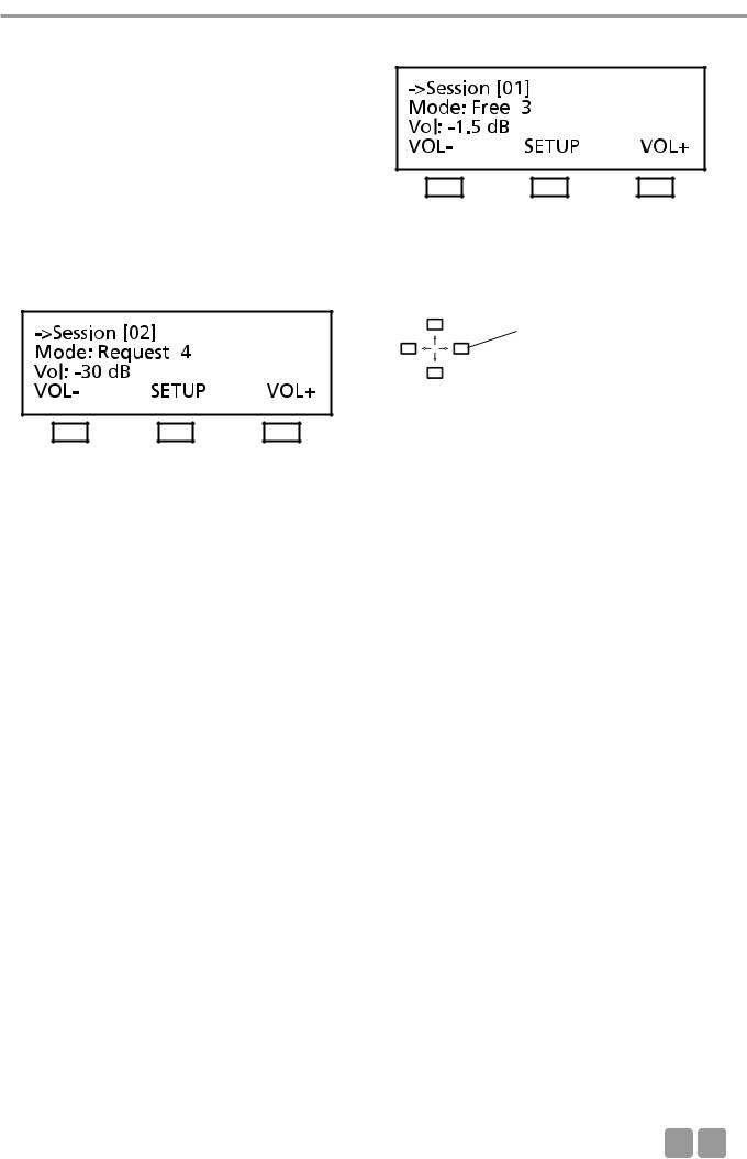
3.3.2Main menu
The main menu displays:
the session number (here it is session 01), the current operating mode (here it is: Free),
the number of open microphones (here the limit is: 3) and the volume of the loudspeakers of the microphone station (here it is -1.5 dB)
MultiSession: How to change to the next meeting
In the MultiSession operation, i.e. when the same MCS-D 200 control unit is used for several meetings, the right and left hand navigator buttons can be used for selecting the individual meetings.
The main menu indicates the settings such as operating mode, limit and volume of the selected meeting. The iCNS software is required for the MultiSession operation.
Use the right and left hand navigator buttons to toggle between the individual meetings.
Conference Volume: VOLand VOL+ buttons
To increase or reduce the volume of the selected meeting (3rd line of the main menu) directly. Press the left hand button (VOL-) to reduce the volume; press the right hand button (VOL+) to increase the volume. The volume is changed in steps of 1.5 dB from -94.5 dB to 0 dB.
SETUP Button
Press the SETUP button to access the SYSTEM SETUP menus and SESSION menus (refer to the illustration of the menu overview of the MCS-D 200 control unit).
Note:
The SYSTEM SETUP menus are for the general system settings = GLOBAL SYSTEM SETTINGS : Define Channels, Message(s), Options, Delegate IDs, Interpreter IDs, Technician IDs and DAI/DDI Management. All devices, channels, messages and options of the whole MCS-D 200 system are defined via these menus.
In the SESSION menus you can prepare settings for individual meetings.
E 13
MCS-D 200 Control Unit
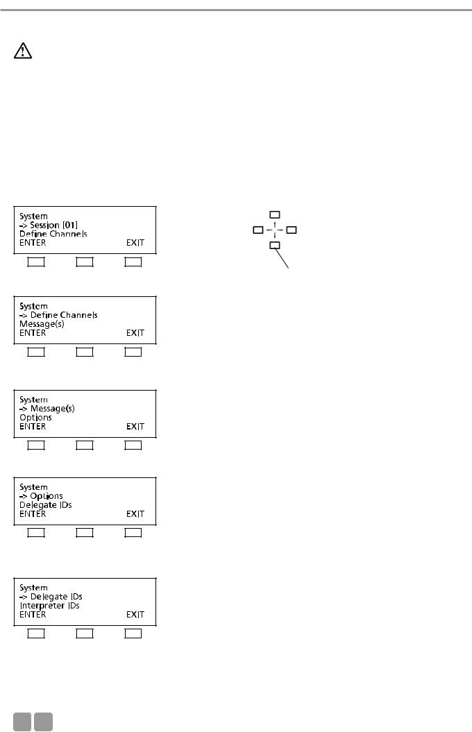
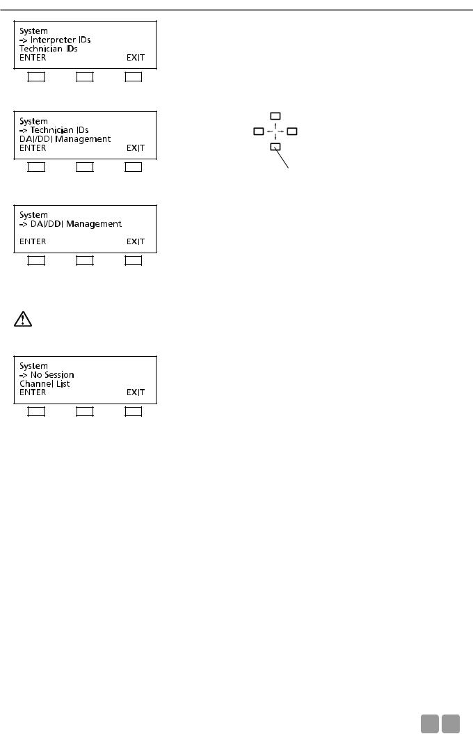
3.3.3System set-up menus
Warning:
In systems using PC and iCNS software the settings are operated via the iCNS software. The set-up menus of the MCS-D 200 control unit cannot be operated to avoid conflicts.
Press the SETUP buttons to access the SYSTEM menus. The arrow indicates the current line. Scroll through the menus by using the up or down navigator buttons. Press the ENTER button to access the submenus. Change individual values by using the left or right hand navigator buttons.
Note:
The SYSTEM SETUP menus are used for the settings of the system level = GLOBAL SYSTEM SETTINGS : Define Channels, Message(s), Options, Delegate IDs, Interpreter IDs, Technician IDs and DAI/DDI Management. All devices, channels, messages and options of the whole MCS-D 200 system are defined via these menus.
In the SESSION menus you can prepare settings for individual meetings.
Use the up or down navigator button for scrolling.
14
MCS-D 200 Control Unit
Use the up or down navigator button for scrolling.
Warning:
In systems using PC and iCNS software the settings are operated via the iCNS software. The set-up menus of the MCS-D 200 control unit cannot be operated to avoid conflicts.
NO SESSION:
iCNS is in the offline mode (conference closed), not in the online mode (conference started).
E 15
MCS-D 200 Control Unit
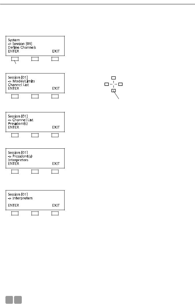
3.3.4Session menus
In the SESSION menus settings for the meeting such as Mode/Limit, Channel List, Presidents, Interpreters are selected for the meeting selected in the main menu.
press the ENTER button
Use the up or down navigator button for scrolling.
16

MCS-D 200 Control Unit
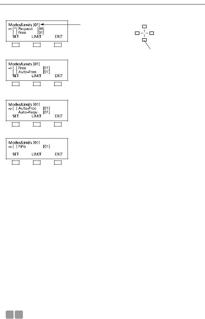
3.3.4.1 Mode / Limit menus
In the MODES/LIMITS menu you can enter the operating mode and number of open microphones (limit) for the selected session (here it is session 01).
press the ENTER button
Free Mode
Each delegate can turn on the microphone of the microphone station if the selected number of open microphones (limit) is not exceeded.
Limit - Free
Determine the maximum number of open microphones. The maximum number is 16.
Request Mode
Delegates enter a request-to-speak by pressing the microphone button. The request-to-speak is registered if the number of possible requests to speak (limit) is not exceeded. By pressing the “0” button the chairman can release the registered request- to-speak.
Limit - Request
Determine the maximum number of requests to speak. The maximum number is 16.
If the limit is set to 2 or higher, the microphones of the registered speakers are turned on simultaneously by pressing the “0” button. If only one speaker is to speak, the limit of the Request mode must be set to 1.
Auto Mode
The request-to-speak/turning on of microphones is one after another. Each delegate can turn on his microphone by pressing the microphone button if the selected limit is not exceeded. If the limit is exceeded, the request-to-speak is registered in the MCS-D 200 control unit. The microphone unit is turned on automatically as soon as a current speaker turns off his microphone.
LIMIT - Auto-Free:
Determine the maximum number of open microphones. The maximum number is 16.
LIMIT - Auto-Request:
Determine the maximum number of simultaneous requests to speak. The maximum number is 16.
FIFO Mode (First In - First Out)
The microphones are turned on one after another. Each delegate can turn on the microphone of his microphone station by pressing the microphone button. If the limit is exceeded, the microphone of the delegate speaking the longest is turned off automatically (first in - first out).
LIMIT - FiFo:
Determine the maximum number of open microphones. The maximum number is 16.
Note:
If the rights of a chairman station are assigned to a microphone station via the MCS-D 200 control unit, the chairman can control the meeting actively by using the following function buttons:
CANCEL button to cancel turned on microphones and/or requests to speak.
PRIORITY button to mute turned on microphones.
NEXT button = press the “0” button to select the next request-to-speak.
PREVIOUS button = press the “9” button to select the previous speaker.
E 17
MCS-D 200 Control Unit
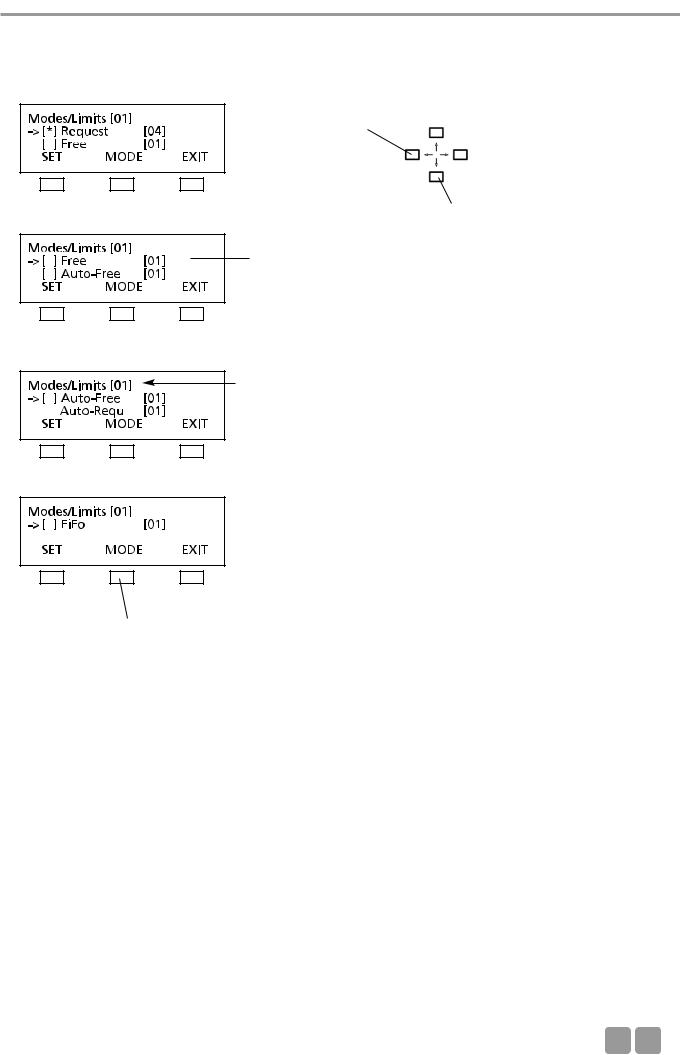
How to set Modes
To select the mode press the SET button. A star in brackets indicates the selected operating mode.
Session number
Use the up or down navigator button for scrolling.
18
MCS-D 200 Control Unit
How to set the Limits
Press the LIMIT button to set the limit. Select the limit by using the right or left hand navigator buttons. Press the MODE button to return to the MODE menu.
Change LIMIT:
Press the left or right hand navigator button.
Use the up or down navigator button for scrolling.
Cursor is flashing
Session number
Press MODE button to return to the MODE menu.
E 19
MCS-D 200 Control Unit
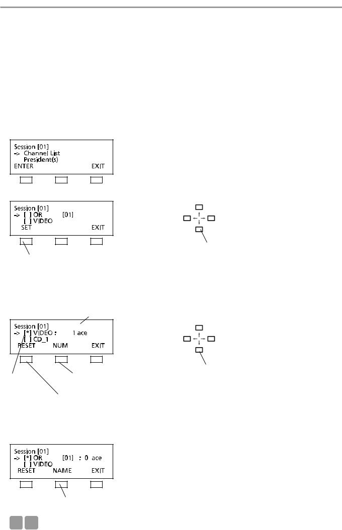
3.3.4.2 Channel List
In the menu CHANNEL LIST you can prepare and edit a list of all required channels. All channels have to be defined in the menu DEFINE CHANNELS (refer also to the chapter 3.3.5 “Define Channels”), because the channel list is basing on the predefined channels.
Whenever the delegate presses the language/channel selector button of his microphone station, the list is displayed. The channel list includes the OR channel, language channels or other channels such as music channels.
For the interpreter stations you can select channels from this channel list.
In the menu CHANNEL LIST you can...
1. ...scroll through the channel list with all predefined channels of the whole system. 2. ...prepare a channel list for the selected session:
•select required channels (set/reset)
•name and number channels
Note: Channels are added by pressing the SET button. A channel description consists of a maximum of 3 characters. The language channels are encoded according to the international MARC language code (refer to chapter 11. “List of Language Codes”).
Press the SET button to add OR channel to the channel list
Use the up or down navigator button for scrolling.
Use the up or down navigator buttons to scroll through the list of all predefined channels in the menu DEFINE CHANNEL. Press the SET button to add a selected channel to the channel list. The star * identifies the selected channel.
Adapt the number and description for the MCS-D 2073 display
The star * identifies the selected channel
Press the NUM button to change the number
Press the RESET button to remove selected channel from the channel list
Use the up or down navigator button to change the channel number
When the NUM button is pressed the cursor goes to the channel number. Use the up or down navigator button to change the number.
Press the NAME button to change the channel description
20
MCS-D 200 Control Unit
When the NAME button is pressed, the cursor goes to the channel description (refer to illustration). The description can be changed as described in the following:
Note:
1.By pressing the right or left hand navigator buttons you can assign a code of the international language list to a language channel (refer to chapter 11. “List of Language Codes”).
2.For other channels you can create another description with a maximum of three characters from a predetermined list. Move the cursor to the position with the left or right hand navigator buttons and scroll through the list of characters with the up and down navigator buttons.
A code of the international language list is assigned to a language channel:
press the EDIT button
Use the right or left hand navigator button to scroll through the international language list.
press the ENTER button to confirm
For any other channel you can select a maximum of 3 characters from a list:
Use the right or left hand navigator button to move the cursor to the next position
 Use the up or down navigator button to press the EDIT button scroll through the list to select the desired
character
When the EDIT button is pressed, the cursor goes to the first choice. Use the up or down navigator button to select a character from the list. Then use the right or left hand navigator button to move the cursor to the next choice etc.
press the ENTER button
E 21
MCS-D 200 Control Unit
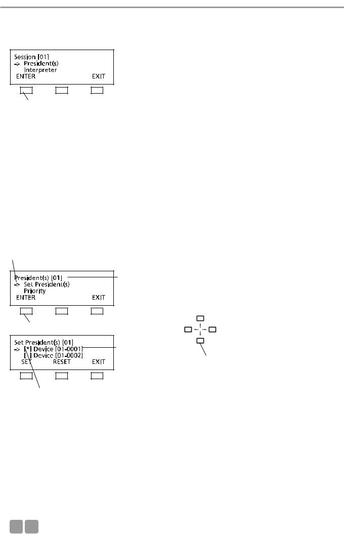
3.3.4.3 President(s)
In the PRESIDENTS menu you can assign the functions of a chairman station such as CANCEL, PRIORITY, PREVIOUS or NEXT to any microphone station in the selected session (here: session 01).
press the ENTER button
The following items refer to chairman stations:
•Each chairman can turn on his microphone at any time, regardless of the selected limit.
•Any number of microphone stations can be programmed as chairman stations.
•Chairman stations can be assigned to different levels (0-99), each level with any number of chairman stations.
•By using the PRIORITY button the chairmen of a higher level can mute all microphones of the delegate stations and the chairman stations of a lower level.
•Chairman stations of the same level, however, cannot be muted by using the PRIORITY button.
•Depending on the operating mode, all chairmen can turn off the microphones of all delegate stations by using the CANCEL button.
•By using the NEXT button chairman can release requests to speak and by using the PREVIOUS button they can ask previous speakers to speak once again.
How to program Chairman Stations (SET/RESET)
The arrow indicates the active line.
Session number
press the ENTER button
Device ID
Use the up or down navigator button to scroll through the menu
The star indicates the chairman station
Each delegate station features a device ID number (refer to chapter 3.3.7 “Delegate IDs” and 3.3.7.2 “Set IDs”). Use the up or down navigator button to scroll to the microphone station with the appropriate ID which is to be programmed as a chairman station. The arrow indicates the selected microphone station. Then press the SET button to assign the functions of a chairman station to this microphone station. In this way you can program any number of microphone stations as chairman stations. The star in brackets identifies all chairman stations.
If you would like to cancel the chairman functions of a microphone station, use the up or down navigator button to scroll to the microphone station with the appropriate ID. The arrow indicates the selected microphone station. Press the RESET button to cancel the chairman functions of the selected microphone station. The star is removed.
Press the EXIT button when all chairman stations are determined. In the PRIORITY LEVEL(S) menu you can then assign the chairman stations to different levels.
22
MCS-D 200 Control Unit
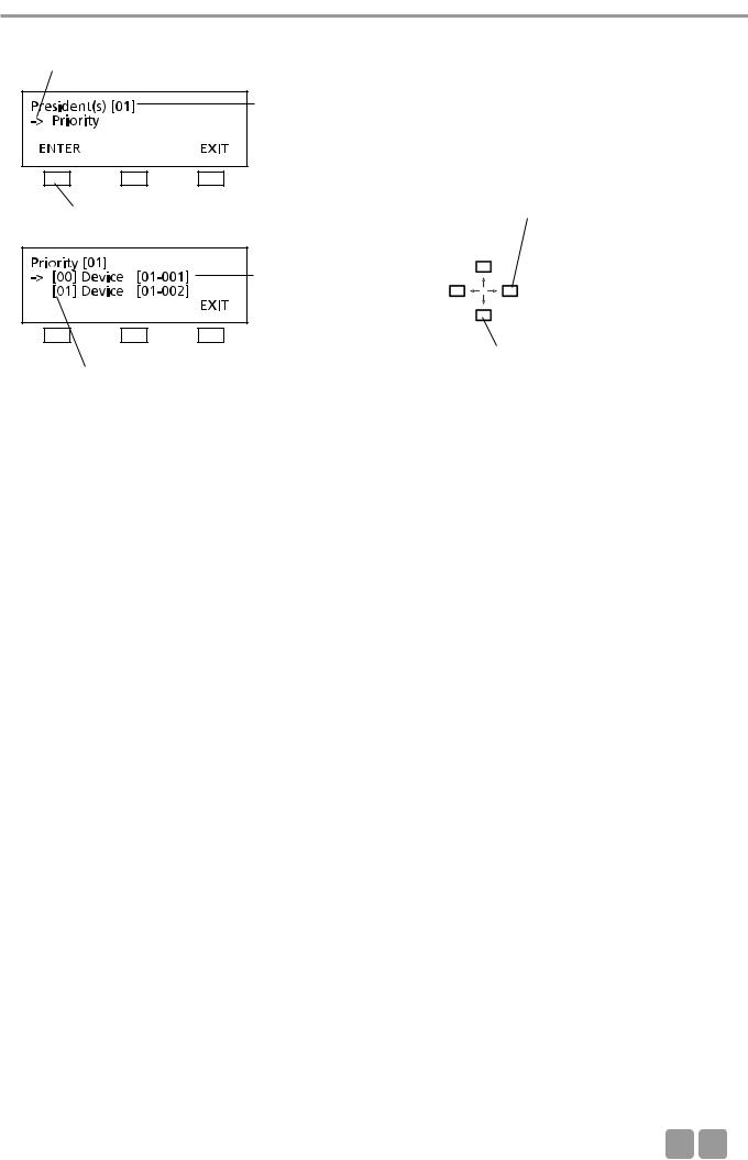
PRIORITY LEVEL(S) for Chairman Stations
The arrow indicates the active line.
session number
press the ENTER button
Device ID
Use the right or left hand navigator button to change the level
|
|
Use the up or down navigator |
|
|
button for scrolling |
Level 0-99 |
|
|
|
|
|
|
|
|
All microphone stations which have been programmed as chairman stations in the SET PRESIDENT(s) menu are listed here. You can assign a level to each chairman station. “0” is the highest level, “99” the lowest. For each level any number of microphone stations is possible. The standard setting is level “0”. If you want to select a different level for a microphones station, use the up or down navigator button to choose the microphone station. Then use the right or left hand navigator button to change the level.
In the example above the chairman station 0001 is on a higher level than the chairman station 0002. If the chairman holds down the PRIORITY button of the microphone station 0001, the microphone of the chairman station 0002 is muted along with the delegate stations.
E 23
MCS-D 200 Control Unit
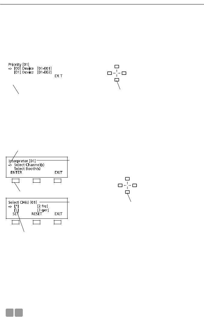
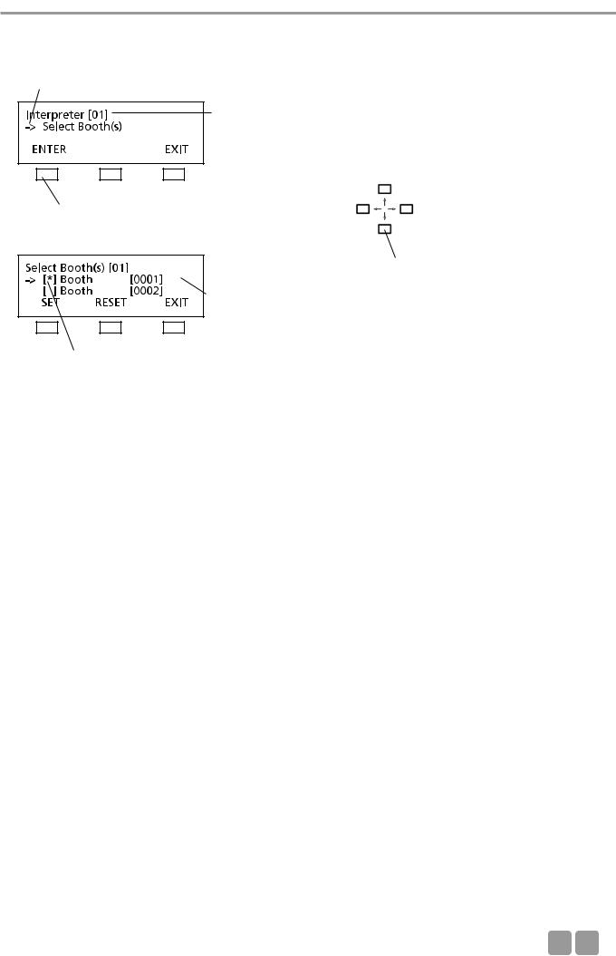
3.3.4.4 Interpreter
In the INTERPRETER menu you can prepare a list of all required interpreter’s channels from the list of session channels for the selected session (here: session 01) (refer also to chapter 3.3.4.2 “Channel List”). The list includes only channels required for interpreters, i.e. all channels for the preselection of the relay and output channels.
When the relay channel or PRE SELECT output channel button of the MCS-D 202 interpreter station is pressed, the list of the interpreter channels is displayed.
Then select from the booth list all booths required for the selected session (refer to chapter 3.3.7.1 “ID List”).
|
|
|
|
|
|
|
|
|
|
|
Use the up or down navigator button to |
|
|
|
|
|
|
|
|
|
|
|
|
|
|
|
|
|
|
|
|
|
|
|
|
|
|
|
|
|
|
|
|
|
|
|
|
|
|
|
|
|
|
|
|
|
|
|
|
|
|
|
|
|
|
|
|
|
|
|
|
|
|
|
|
|
|
|
|
|
|
|
|
|
|
|
|
|
|
|
|
|
|
|
scroll through the menu |
|
|
press ENTER button |
|
|
|
|
|
||||
|
|
|
|
||||||||
|
|
|
|
|
|
|
|
|
|
|
|
How to prepare the list of interpreter’s channels for the session
In the INTERPRETER menu you can prepare a list of all required interpreter’s channels from the list of the session channels (refer to chapter 3.3.4.2 “Channel List”) for the selected session (here: session 01).
The arrow indicates the active line.
Session number
press the ENTER button
Session number
Use the up or down navigator button to scroll through the menu
The star identifies the selected channel.
Use the up or down navigator button to select the channel which is to be added to the interpreter’s channel list. Then press the SET button. The star identifies the selected channel. Repeat these steps to add more channels to the list.
Press the RESET button if you want to remove a selected channel from the interpreter’s channel list. The star is removed. Repeat these steps if you want to remove more channels from the interpreter’s channel list.
Press the EXIT button to leave this menu.
24
MCS-D 200 Control Unit
How to select the required interpreter’s booth(s) for the session
Select all booths required for the selected session from the booth list (refer to chapter 3.3.7.1 “ID List”).
The arrow indicates the active line.
Session number
press the ENTER button
Use the up or down navigator button to scroll through the menu
Booth number
The star identifies the selected booth.
Use the up or down navigator button to select the booth required for the session (here: 01). Then press the SET button. The star identifies the selected booth. Repeat these steps to select more booths.
To remove a selected booth from the session press the RESET button. The star is removed. Repeat these steps if you want to remove more booths from the session.
Press the EXIT button to leave the menu.
E 25
MCS-D 200 Control Unit
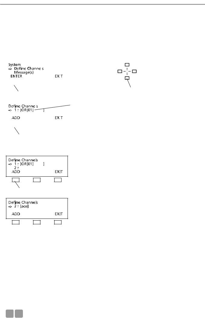
3.3.5Define Channels
In the DEFINE CHANNELS menu all channels required for the whole system are defined, added or removed. By using these defined channels the lists of the session channels are prepared for the individual sessions (refer to chapter 3.3.4.2 “Channel List”).
Note:
•The OR channel does always exist in the list and may neither be edited nor deleted.
•A channel currently in use may neither be edited nor deleted.
|
|
|
|
|
|
|
|
|
|
|
|
|
|
Use the up or down navigator button to |
|
|
|
|
|
|
|
|
|
|
|
|
|
|
|
||
|
|
|
|
|
|
|
|
|
|
|
|
|
|
||
|
|
|
|
|
|
|
|
|
|
|
|
|
|
||
|
|
|
|
|
|
|
|
|
|
|
|
|
|
||
|
|
|
|
|
|
|
|
|
|
|
|
|
|
||
|
|
|
|
|
|
|
|
|
|
|
|
|
|
||
|
|
|
|
|
|
|
|
|
|
|
|
|
|
||
|
|
|
|
|
|
|
|
|
|
|
|
|
|
||
|
|
|
|
|
|
|
|
scroll through the menu |
|||||||
|
|
press the ENTER button |
|
|
|
|
|
||||||||
|
|
|
|
|
|
|
|
|
|
|
|
|
|
|
|
|
|
|
|
|
|
|
|
|
|
|
|
|
|
|
|
|
|
|
|
|
|
|
|
|
|
|
|
OR channel of session 1 |
|
||
|
|
|
|
|
|
|
|
|
|
|
|||||
|
|
|
|
|
|
|
|
|
|
|
|
|
|
|
|
|
|
|
|
|
|
|
|
|
|
|
|
|
|
|
|
|
|
|
|
|
|
|
|
|
|
|
|
|
|
|
|
|
|
|
|
|
|
|
|
|
|
|
|
|
|
|
|
|
|
|
|
|
|
|
|
|
|
|
|
|
|
|
|
|
|
|
|
|
|
|
|
|
|
|
|
|
|
|
|
|
|
|
|
|
|
|
|
|
|
|
|
|
|
|
|
press the ADD button
Press the ADD button to add a new channel.
press the ADD button
Note:
1.For language channels you may select a name from an international language code list (refer to chapter 11. “List of Language Codes”) by using the right or left hand navigator button.
2.For any other channel you may edit the code (up to 3 characters). By using the right or left hand navigator button you can place the cursor at the desired position and by using the up or down navigator button you can scroll through a list of characters.
3.A defined channel may comprise a maximum of 6 characters.
26
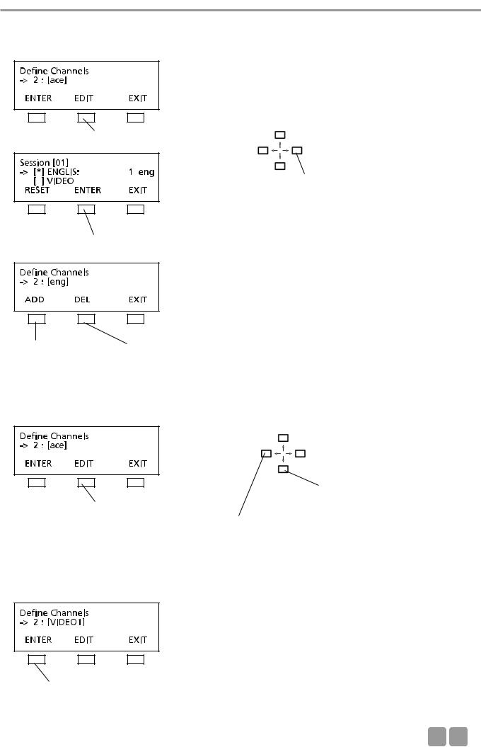
MCS-D 200 Control Unit
For a language channel select the name from a list of international language codes (refer to chapter 11. “List of Language Codes”):
press the EDIT button to open the channel list
Use the right or left hand navigator button to scroll through the list of language codes
press the ENTER button to confirm
press the ADD button to define a new channel
press the DEL button to delete a channel
For any other channel which does not receive an international language code, you can select individual characters from a list of characters:
press the EDIT button
Use the right or left hand navigator button to go with the cursor to the next character position
Use the up or down navigator button to scroll through the list to find the desired character
When the EDIT button is pressed the cursor goes to the first position. Use the up or down navigator button to select a character from the list. Use the right or left hand cursor button to go to the next position etc.
press the ENTER button to confirm
E 27
MCS-D 200 Control Unit
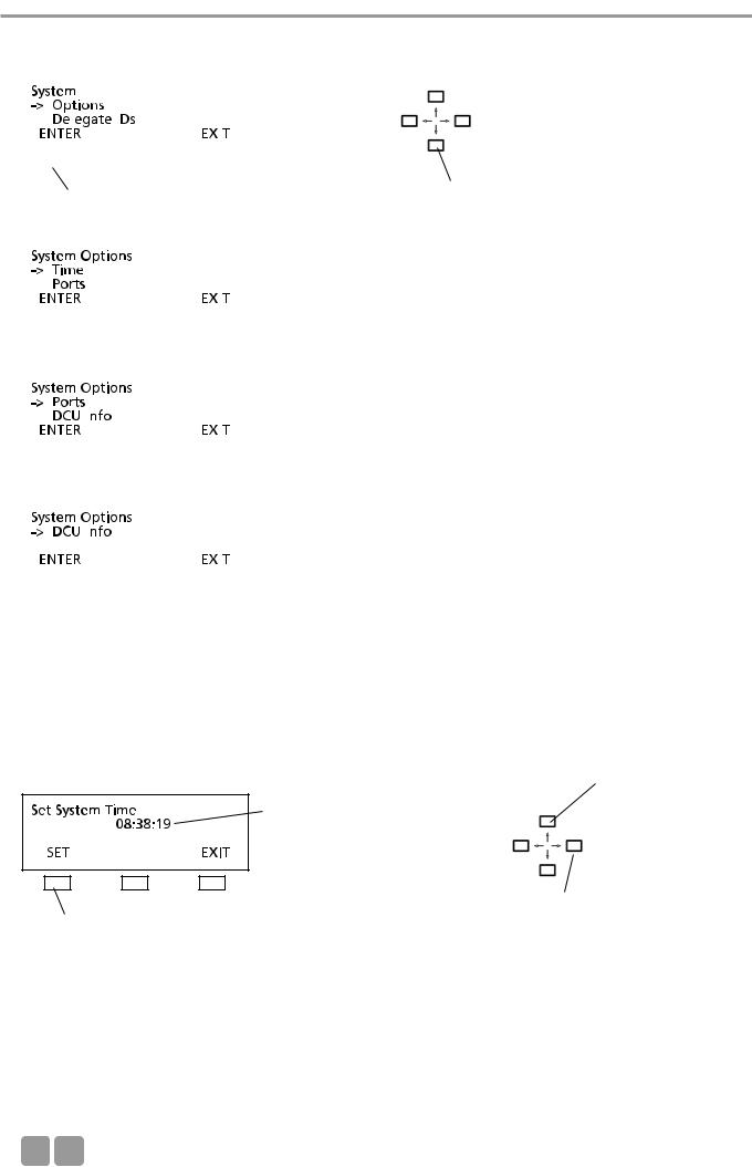
3.3.6Options
|
|
|
|
|
|
|
|
|
|
|
|
|
Use the up or down navigator button for |
|
|
|
|
|
|
|
|
|
|
|
|
|
|
|
|
|
|
|
|
|
|
|
|
|
|
|
|
|
|
|
|
|
|
|
|
|
|
|
|
|
|
|
|
|
|
|
|
|
|
|
|
|
|
|
|
|
|
|
|
|
|
|
|
|
|
|
|
|
|
|
|
|
|
|
|
|
|
|
|
|
|
|
|
|
|
|
|
|
|
|
|
|
|
|
|
|
|
|
|
|
|
|
|
|
|
|
|
|
|
|
|
|
|
press the ENTER button |
|
||||||||||
|
|
|
scrolling |
||||||||||
|
|
|
|
|
|
|
|
|
|
|
|
|
|
|
|
|
|
|
|
|
|
|
|
|
|
|
|
|
|
|
|
|
|
|
|
|
|
|
|
|
|
|
|
|
|
|
|
|
|
|
|
|
|
|
|
|
|
|
|
|
|
|
|
|
|
|
|
|
|
|
|
|
|
|
|
|
|
|
|
|
|
|
|
|
|
|
|
|
|
|
|
|
|
|
|
|
|
|
|
|
|
|
|
|
|
|
|
|
|
|
|
|
|
|
|
|
|
|
|
|
|
|
|
|
|
|
|
|
|
|
|
|
|
|
|
|
|
|
|
|
|
|
|
|
|
|
|
|
|
|
|
|
|
|
|
|
|
|
|
|
|
|
|
|
|
|
|
|
|
|
|
|
|
|
|
|
|
|
|
|
|
|
|
|
|
|
|
|
|
|
|
|
|
|
|
|
|
|
|
|
|
|
|
|
|
|
|
|
|
|
|
|
|
|
|
|
|
|
|
|
|
|
|
|
|
|
|
|
|
|
|
|
|
|
|
|
|
|
|
|
|
|
|
|
|
|
|
|
|
|
|
|
|
|
|
|
|
|
|
|
|
|
|
|
|
|
|
|
|
|
|
|
|
|
|
|
|
|
|
|
|
|
|
|
|
|
|
|
|
|
|
|
|
|
|
|
|
|
|
|
|
|
|
|
|
|
|
|
|
|
|
|
|
|
|
|
|
|
|
|
|
|
|
|
|
|
|
|
|
|
|
|
|
|
|
|
|
|
|
|
|
|
|
|
|
|
|
|
|
|
|
|
|
|
|
|
|
|
|
|
|
|
|
3.3.6.1 Time
In the TIME menu the system time for the MCS-D 200 control unit, MCS-D 202 and MCS-D 2073 microphone stations can be set manually (refer to chapter 7.1.6 “Menu settings”) in the format HOURS – MINUTES – SECONDS.
When the iCNS software is started, the system time is refreshed automatically.
Current time setting


 Refreshed time setting
press the SET button to confirm
Use the up or down navigator button to edit the numbers
Use the right or left hand navigator button to go from HOURS to MINUTES and SECONDS
The current system time is displayed in the CURRENT TIME line as: HOURS : MINUTES : SECONDS.
You can change the time in the line below. Use the right or left hand navigator button to go from HOURS to MINUTES and SECONDS. Use the up or down navigator button to set the new values and press the SET button to confirm.
28
 Loading...