


Precautions
MODEL 23-12 (120V)
MODEL 25-12 (240V)
!DISCONNECT ELECTRICAL POWER PRIOR TO MAINTENANCE AND CLEANING.
!ALL MAINTENANCE AND CLEANING MUST BE PERFORMED ACCORDING TO THIS MANUAL.
!NEVER USE ANY SHARP OBJECTS, CAUSTIC OVEN CLEANER, OR DEGREASER TO CLEAN MACHINE OR PRESS PLATES.
!IN CASE OF POWER FAILURE OR EMERGENCY, SHUT DOWN MACHINE.
!DO NOT CONNECT TO A CIRCUIT OPERATING AT MORE THAN 150 VOLTS TO GROUND.
1 |
10-07-14 |

Table of Contents
Precautions..................................................................................................................................... |
1 |
Table of Contents............................................................................................................................ |
2 |
Policy & Procedure for returning parts............................................................................................ |
3 |
Warnings......................................................................................................................................... |
4 |
Storyboards..................................................................................................................................... |
4 |
Delivery & Damage......................................................................................................................... |
4 |
Assembly......................................................................................................................................... |
4 |
Specifications.................................................................................................................................. |
5 |
Components.................................................................................................................................... |
6 |
Initial Adjustments........................................................................................................................... |
7 |
Control Panel.................................................................................................................................. |
7 |
Temperature Control Instructions.................................................................................................... |
8 |
Start up and Shut down Procedure................................................................................................. |
9 |
Operation Troubleshoot................................................................................................................. |
10 |
Cleaning........................................................................................................................................ |
13 |
Press Plate Adjustment................................................................................................................. |
19 |
Maintenance.................................................................................................................................. |
21 |
Dough Making............................................................................................................................... |
22 |
Tortilla Making............................................................................................................................... |
27 |
Flour Tortilla Recipe...................................................................................................................... |
35 |
Closing Statement......................................................................................................................... |
37 |
Parts and Pictures......................................................................................................................... |
38 |
Decal Locator Assembly................................................................................................................ |
44 |
Warranty........................................................................................................................................ |
45 |
Neither this manual nor any part may be reproduced or transmitted in any form or by any means, electronic or mechanical, including photocopying, microfilming, and recording, or by information storage and retrieval system, without permission in writing from Bakery Equipment & Service Co., Inc.
2

Policy & Procedure for Returning BE&SCO Parts
Returning BE&SCO Parts:
To return any BE&SCO parts you must follow BE&SCO’s procedure for returning. No returns will be accepted outside of this procedure. BE&SCO warrants parts for 1 year or 3000 hours, which ever comes first, for full credit. This does not include wear and tear items as stated in our manual.
This warranty does not cover any defect due to or resulting from handling, abuse, misuse, improper maintenance and cleaning, or harsh chemical action, nor shall it extend to any unit from which the serial number has been removed or altered, or acts of God. Adjustments such as calibrations, leveling, tightening of fasteners or plumbing connections normally associated with original installation are the responsibility of the dealer or installer and not of BAKERY EQUIPMENT & SERVICE CO., INC.
Procedure for Returning BE&SCO Parts:
1.Call BE&SCO Parts Department at 1-800-683-0928 or email parts@bescomfg.com. At this time you may request a repair and return, advance replacement or a credit of the component. The Parts Department will then issue you an RA (Return Authorization) number to return the BE&SCO part. After you are issued an RA number. You have 10 working days to return the old part for full credit or you will be invoiced for the new part.
2.Package the component and a detailed description of what is wrong with the component. Write the RA number on the outside of the package in a visible place and send the return to:
BE&SCO - Parts Department
RA#
1623-27 N. San Marcos
San Antonio, TX 78201
To obtain warranty on return parts the customer or the end user will be responsible for that particular item to be shipped back to BE&SCO. Freight is not covered under warranty, going or coming. BE&SCO recommends that you insure any parts that are being returned to BE&SCO, as BE&SCO Inc. is not responsible for any damage or loss that occurs during shipping. If the part is damaged or lost during shipping, BE&SCO will not be responsible for repair or replacement of the parts.
3

Warnings
In case of power failure, shut down machine.
For emergency shutdown, push on/off button to off.
Storyboards
The laminated poster included in your shipment is called a Storyboard. A Storyboard shows how to operate or care for the machine. It should be posted on a wall close by the machine. Both front and back have the same information but in two different languages – Spanish and English.
Delivery & Damage
We firmly pack all our equipment and strap them on heavy wooden skids before giving them to the shipping company. After we give the merchandise to the shipping company, they are responsible for delivering your purchase; therefore, BE&SCO will not be responsible for the loss or damage of your shipment. If you find your purchase damaged, call the shipping company.
Assembly
1.) Remove the machine from the shipping pallet.
2.) From the end opposite of the plug, put the Exit Slide over the lip below the Press Plates.
3.) Turn the legs clockwise or counter clockwise to tighten them.
4.) Adjust the legs’ height. They can go up to 1 1/2” high.
4
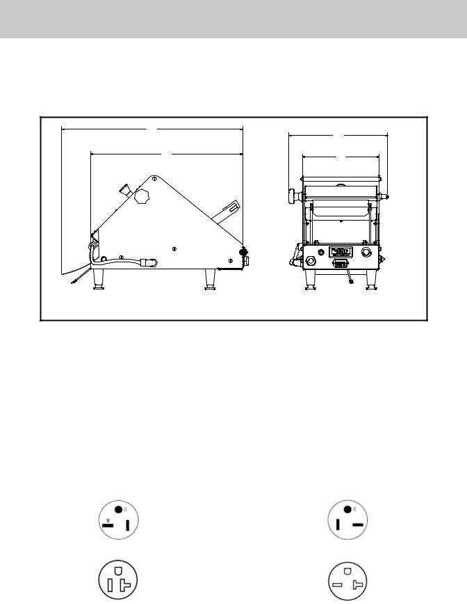
Specifications
The Mini Wedge works on 120 volt grounded circuits. The voltage and phase must be compatible with the power supply in use to safely operate. Any installation not matching the electrical specifications for the machine will void your warranty and may damage the Mini Wedge. Machine installation must follow local codes, or the National Electrical Code ANSI/NFPA 70-1984 (in Canada-CSA Std. C22.1).
22.70 |
|
|
12.39 |
19.06 |
9.62 |
|
Model 23-12 |
|
|
Model 25-12 |
|
Voltage................................................. |
120 VAC |
|
Voltage................................................. |
240 VAC |
Cycles...................................................... |
60 Hz |
|
Cycles...................................................... |
60 Hz |
Phase....................................................... |
Single |
|
Phase....................................................... |
Single |
Amperage....................................................... |
15 |
|
Amperage....................................................... |
13 |
Total Power Usage................................ |
1800 W |
|
Total Power Usage................................ |
3000 W |
|
|
|
|
|
This machine has a 6 ft. (180cm) long electrical cord with a US standard 3 prong plug.
|
Model 23-12 |
|
Model 25-12 |
|
Plug: |
straight blade |
Plug: |
straight blade |
|
configuration, |
configuration, |
|||
NEMA 5-20P |
2 pole, 3 wire |
NEMA 6-20P |
2 pole, 3 wire |
|
(125V ~) |
grounding |
(250V ~) |
grounding |
|
Receptacle: |
configuration, |
Receptacle: |
configuration, |
|
NEMA 5-20R |
2 pole, 3 wire |
2 pole, 3 wire |
||
NEMA 6-20R |
||||
(125V ~) |
grounding |
grounding |
||
(250V ~) |
||||
|
|
|||
|
|
|
5

Components
6
Initial Adjustments
The installation will be unfinished until a Qualified Service Person makes some initial adjustments, tests and an inspection of your machine. The warranty does not cover these adjustments.
A Qualified Service Person is an employee of a firm, a corporation or a company that will:
1.Install, connect, repair, service, and replace parts of the Mini Wedge Press either electrical or mechanical.
2.Follow rules and regulations of the National Electrical Code, ANSI/NFPA 70 or Canada’s CSA STD. C22.1, or any other local codes.
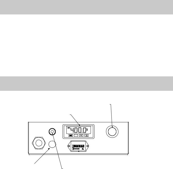
Control Panel
ON/OFF PUSH BUTTON
TEMPERATURE CONTROLLER
Model 25-12 has a 2nd Fuse
 HOURMETER
RESETTABLE FUSE
1.The PUSH BUTTON turns the unit on and off.
2.The TEMPERATURE CONTROLLER will display the temperature of the press plates.
3.The HOURMETER shows the amount of hours on the machine.
4.The RESETTABLE FUSE will trip if there is an overload.
7
8
TEMPERATURE CONTROL INSTRUCTIONS
*THERE ARE TWO TYPES OF TEMPERATURE CONTROLLERS THAT WILL COME INSTALLED IN YOUR MACHINE PLEASE DETERMINE WHETHER YOU HAVE TYPE A OR TYPE B AND FOLLOW INSTRUCTIONS BELOW
TYPE A
INSTRUCTIONS:
WHEN POWERED UP UNIT WILL FLASH SEVERAL TIMES
PLATE TEMPERATURE WILL DISPLAY ONCE FLASHING STOPS
TO CHANGE TEMPERATURE SET POINT: -PRESS SET BUTTON (A) ONCE
-SET TEMPERATURE IS NOW DISPLAYED
A  B
B 
 C
C
-USE UP AND DOWN BUTTONS (B) & (C) TO CHANGE SET POINT -PRESS SET BUTTON (A) AGAIN TO EXIT
-PLATE TEMPERATURE IS NOW DISPLAYED
TYPE B |
|
|
|
|
INSTRUCTIONS: |
|
|
WHEN POWERED UP UNIT WILL DISPLAY F |
|
|
PLATE TEMPERATURE WILL DISPLAY NEXT |
|
|
TO CHANGE TEMPERATURE SET POINT: |
|
C |
-PRESS SET BUTTON (A) ONCE |
|
-SP (SET POINT) WILL DISPLAY |
|
|
|
-PRESS SET BUTTON (A) A SECOND TIME |
|
|
-SET TEMPERATURE WILL DISPLAY |
|
|
-USE UP AND DOWN BUTTONS (B) & (C) TO CHANGE SET POINT |
A |
B |
-PRESS SET BUTTON (A) AND DOWN BUTTON (B) AT THE SAME TIME TO EXIT |
-PLATE TEMPERATURE IS NOW DISPLAYED |
Instructions Control Temperature
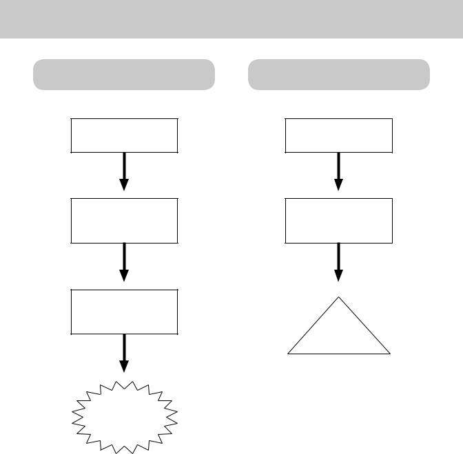
Operation
Startup
PUSH IN
PUSH BUTTON
The temperature controller will turn on.
Wait for
the temperature to reach 385°F - 400°F
You’re ready to make Tortillas!
Shutdown
PUSH IN
PUSH BUTTON
Allow
Press Plates
to cool.
Shutdown
Complete
Clean Unit.
9
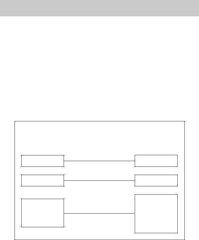
Operation Troubleshooting
|
|
Problem 1: Power switch light does not glow. |
|||
|
|
|
|
|
|
|
Cause |
|
|
Solution |
|
|
|
|
|
||
|
|
|
|
|
|
|
|
|
|
|
|
|
No power to machine. |
|
Check branch line |
|
|
|
|
circuit breaker. |
|
||
|
|
|
|
|
|
|
|
|
|
|
|
|
|
|
|
|
|
|
Machine not |
|
|
Plug into outlet. |
|
|
plugged in. |
|
|
|
|
|
|
|
|
|
|
|
|
|
|
|
|
Problem 2: Thermostat Indicator Light does not glow.
Cause |
|
Solution |
|
||
|
|
|
Machine not plugged in.
No power to machine
Plate wire harness connectors not plugged into electrical control box.
Plug into outlet.
Check circuit breaker to outlet.
Loosen electrical control box knobs, remove electrical raceway and securely plug in connectors to back of electrical control box.
10

Operation Troubleshooting
Problem 3: Thermostat Indicator Light glows but temperature not being controlled.
Cause |
|
Solution |
|
||
|
|
|
Plate wire harness connectors not plugged into control box.
Thermal fuse has failed.
Loosen electrical control box screws, remove electrical raceway and securely plug in connectors to back of control box.
Call Qualified
Service Person
Problem 4: Top Press Plate won’t heat.
Cause |
|
Solution |
|
||
|
|
|
Top Press Plate harness not plugged in.
Thermal fuse has failed.
Relay not functioning.
Check if power hardness is plugged in.
Call Qualified
Service Person
Call
Qualified Service
Person.
11

Operation Troubleshooting
Problem 5: Bottom Press Plate won’t heat.
Cause |
|
Solution |
|
||
|
|
|
Bottom Press Plate power harness not plugged in.
Relay not functioning.
Check bottom Press Plate harness is plugged in.
Call
Qualified Service
Person.
12
 Loading...