

Page 1
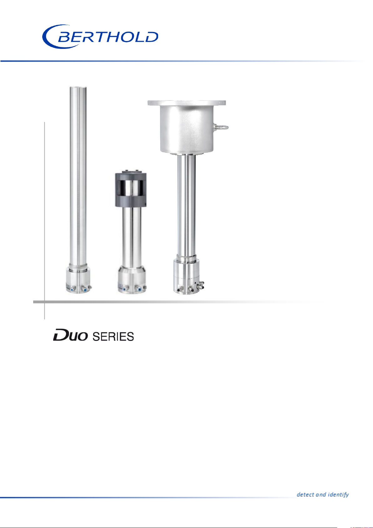
Detectors
LB 4700
Operating Manual
56926BA2
Rev. No.: 02, 04/2019
Embedded Software as of vers. 12.00.00
Page 2

Page 3

BERTHOLD TECHNOLOGIES GmbH & Co. KG
Calmbacher Str. 22
75323 Bad Wildbad, Germany
www.berthold.com
Telephone +49 7081 177-0
Fax +49 7081 177-100
Page 4

Page 5

LB 4700 Table of Contents
1
Table of Contents
1 General Information ........................................................................................... 3
1.1 Applicable Documents ................................................................................................. 3
1.2 Conformity .................................................................................................................... 3
1.3 Approvals and certificates ........................................................................................... 3
1.4 Symbols Used on the Device ........................................................................................ 3
1.5 About this Operating Manual ..................................................................................... 5
Structure of the Operating Manual ............................................................................ 7
Structure of Warnings .................................................................................................. 9
2 Safety ................................................................................................................ 11
2.1 Dangers and safety measures .................................................................................... 11
2.2 Proper Use ................................................................................................................... 11
2.3 Qualification of the Personnel .................................................................................. 12
2.4 Operator's Obligations ............................................................................................... 13
3 System Description ........................................................................................... 15
3.1 Measuring Principle .................................................................................................... 15
3.2 Storage ........................................................................................................................ 16
3.3 System Components ................................................................................................... 17
Overview XP variant (Class/Division) ......................................................................... 17
Overview ATEX/IECEx variant .................................................................................... 18
Rod and point detector .............................................................................................. 19
Scintillator ................................................................................................................... 19
Software ...................................................................................................................... 20
Accessories and Options ............................................................................................. 20
4 Installation ........................................................................................................ 21
4.1 Safety Instructions ...................................................................................................... 21
4.2 Unpacking / Scope of Delivery ................................................................................... 22
4.3 Installation of Mounting Clamps ............................................................................... 23
4.4 Installation on a Pipeline ........................................................................................... 25
4.5 Installation on a Vessel............................................................................................... 26
4.6 Installation on a Conveyor Belt ................................................................................. 28
5 Electric Installation ........................................................................................... 29
5.1 Initial Start-up ............................................................................................................. 29
5.2 Reuse of Detectors ...................................................................................................... 31
6 Operation.......................................................................................................... 33
6.1 Operating Concept ..................................................................................................... 33
6.2 PC Software ................................................................................................................. 34
6.3 Operating the PC Software ........................................................................................ 37
6.4 The PC Software Menu............................................................................................... 38
Monitor ....................................................................................................................... 39
Identification .............................................................................................................. 41
Reset ............................................................................................................................ 42
Overview ..................................................................................................................... 44
Plateau ........................................................................................................................ 48
Pt 100 ........................................................................................................................... 50
Event Log .................................................................................................................... 54
Event Counter ............................................................................................................. 55
Data Log ...................................................................................................................... 56
7 Troubleshooting ............................................................................................... 59
7.1 System Events .............................................................................................................. 59
8 Maintenance and Repair .................................................................................. 63
56926BA2, Rev. 02, 04/2019
Page 6

1 General Information
LB 4700
2
8.1 Safety Instructions ...................................................................................................... 63
8.2 Software Update ........................................................................................................ 64
8.3 Visual Inspection of Scintillator and Photomultiplier .............................................. 69
8.4 Replacing the Entire Detector ................................................................................... 70
8.5 Replacing the Electronics Module ............................................................................. 71
Disassembling the Electronics Module ...................................................................... 72
Installing the Electronics Module .............................................................................. 73
8.6 Replacing the Scintillator ........................................................................................... 74
Disassembling the Scintillator .................................................................................... 74
Installing the Scintillator ............................................................................................ 74
8.7 Replacing the Scintillator/Multiplier Combination .................................................. 75
9 Accessories ........................................................................................................ 77
9.1 Water Cooling System ................................................................................................ 79
Installation and Connection of the Water Cooling System ..................................... 80
9.2 Conversion Kit for Extended Temperature Range ................................................... 82
9.3 Collimator ................................................................................................................... 83
Collimator Assembly with Water Cooling System .................................................... 84
Collimator Assembly without Water Cooling System .............................................. 85
10 Decommissioning .............................................................................................. 87
10.1 Disposal ....................................................................................................................... 88
56926BA2 Rev. 02, 04/2019
Page 7
LB 4700
1 General Information
3
Observe the operating manual
Electrostatic discharge
Protective earth connection
Equipotential bonding connection
1 General Information
1.1 Applicable Documents
This manual contains the following documents:
• Safety Manual / Explosion Protection Manual, Id. No. 56926BA26
• Technical Information, Id. No. 56926TI
1.2 Conformity
The company Berthold Technologies GmbH & Co. KG hereby declares in its sole
responsibility that the design of this product in the distributed form complies with
relevant EU directives stated in the original declaration of conformity.
This statement shall become void in the case of unauthorised changes or improper
use.
For the original declaration of conformity, please refer to the safety manual / explosion protection manual.
1.3 Approvals and certificates
For approvals and certificates, please refer to the safety manual / explosion protection manual.
1.4 Symbols Used on the Device
Please observe the instructions in this operating manual.
Please note the handling instructions. Electrostatically endangered components. Please observe the instructions in this operating manual.
At this position, connect the protective earth conductor (PE).
At this position, connect the equipotential bonding conductor.
56926BA2, Rev. 02, 04/2019
Page 8

1 General Information
LB 4700
4
No domestic waste
The electric product must not be disposed of in domestic waste.
56926BA2, Rev. 02, 04/2019
Page 9
LB 4700
1 General Information
5
NOTICE
1.5 About this Operating Manual
The product is handed over to you by the manufacturer BERTHOLD TECHNOLOGIES
GmbH & Co. KG (hereinafter referred to as BERTHOLD) in a complete and functionally reliable condition.
This operating manual illustrates how to:
• set up/install the product
• establish the connections to the power supply
• perform measurements
• apply software settings
• install accessories
• carry out maintenance on the product
• fix errors
• disassemble the product
• dispose of the product
Read these instructions thoroughly and completely before working with the product. We have tried to compile all information for safe and proper operation for
you.
However, should questions arise which are not answered in this operating manual,
please contact BERTHOLD.
Store the instructions where they are accessible for all users at all times.
Validity of the Operating Manual
The operating manual is valid from the delivery of the Berthold product to the user
until its disposal. Version and release date of this operating manual can be found
in the bottom of each page. Modification service is not performed by the manufacturer BERTHOLD TECHNOLOGIES GmbH & Co. KG.
The manufacturer reserves the right to make changes to this operating manual at
any time without stating reasons.
The current revision of this operating manual replaces all previous versions.
Target Group
This operating manual is directed at qualified specialist personnel who are familiar
with handling electrical and electronic assemblies as well as with communication
and measuring techniques.
Specialist personnel refers to those who can assess the work assigned to them and
recognise possible dangers through their specialist training, knowledge and experience as well as knowledge of the relevant regulations.
56926BA2, Rev. 02, 04/2019
Page 10

1 General Information
LB 4700
6
Storage Place
This operating manual as well as all product-related documentation relevant to the
respective application must be accessible at all times near the device.
Copyright
This operating manual contains copyright-protected information. None of the
chapters may be copied or reproduced in any other form without prior authorisation from the manufacturer.
56926BA2, Rev. 02, 04/2019
Page 11
LB 4700
1 General Information
7
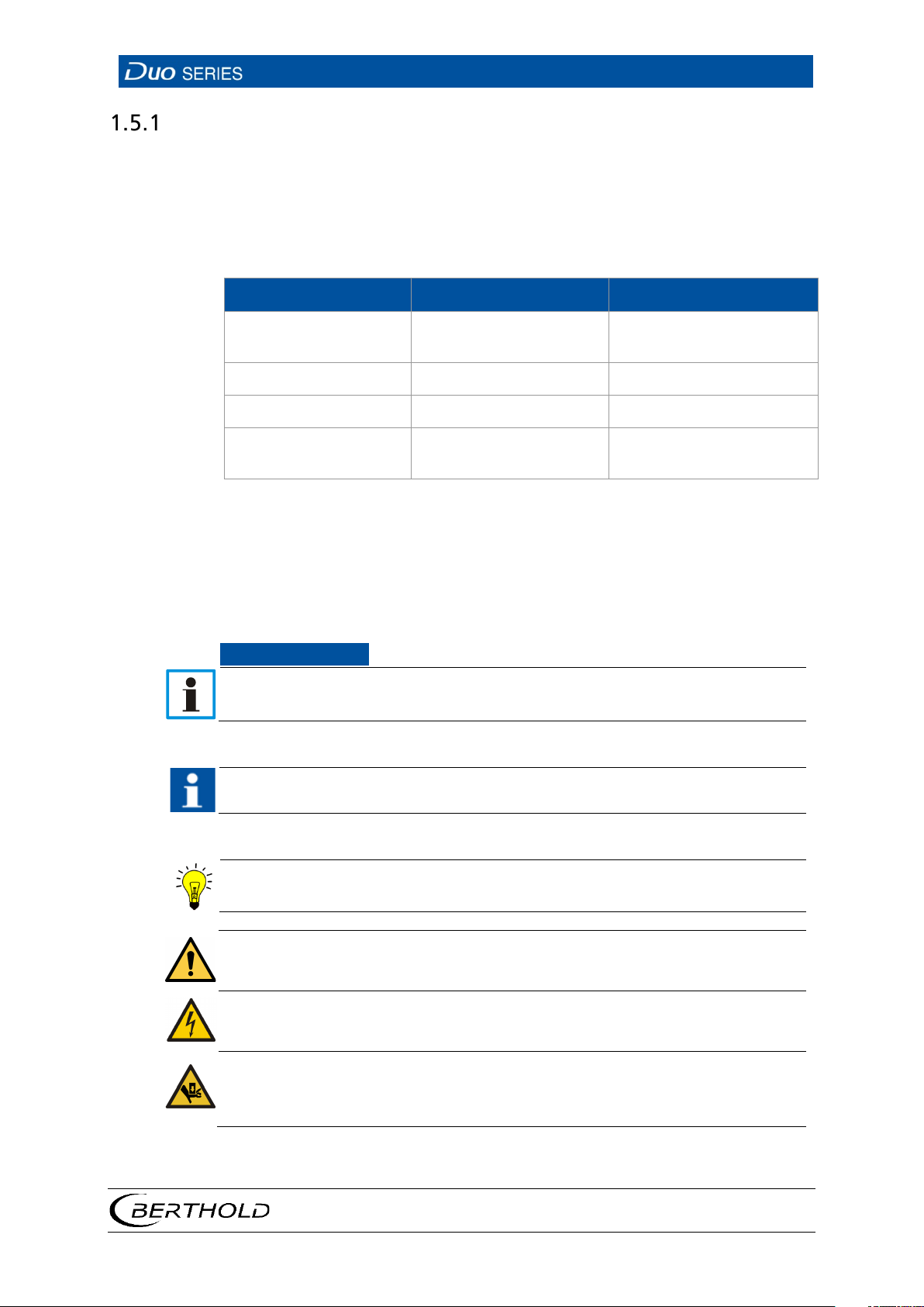
Identifier
Meaning
Example
Quotation mark
Vertical line
Pointed brackets
<Update>
Round brackets
Connect the plug (fig. 1,
NOTICE
IMPORTANT
Tip
General warning symbol
Warning symbol electrical shock
Warning symbol Danger of crushing
Structure of the Operating Manual
This operating manual has been divided into chapters. The order of the chapters
should help you to quickly and properly familiarise yourself with the operation.
Representation
Field in the software inter-
"Calibrating"
face
Path specification Settings | Selection
Keys and buttons
Image reference
item 1)
In the software description, the term "clicking" is used if a process is to be activated. This also refers to the pressing of a button (key) or an area on the touch
display if a mouse is not used for controlling.
Symbols Used
If this information is not observed, deterioration in the operation and/or property damage may occur.
Sections marked with this symbol point out important information on the
product or on handling the product.
Provides tips on application and other useful information.
56926BA2, Rev. 02, 04/2019
Page 12
1 General Information
LB 4700
8
Warning symbol heavy loads
Warning symbol suspended load
Warning symbol explosion hazard
Wear protective helmet
Wear safety shoes
56926BA2, Rev. 02, 04/2019
Page 13
LB 4700
1 General Information
9
Signal Word
Source and consequence
DANGER
imminent
WARNING
potential
CAUTION
potentially dangerous
Structure of Warnings
Explanation, if required
u Prevention
In case of emergency
•
Warning symbols: (warning triangle) draws attention to the hazard.
•
Signal word: indicates the severity of danger.
•
Source: specifies the type or source of danger.
•
Consequence: describes the consequences of non-compliance.
•
Prevention: states how one can avoid the hazard.
•
In case of emergency: specifies which actions are required in the event of
the occurrence of risk.
In this manual, warning instructions before instructions for action refer to risks of
injury or damage to property. The hazard-prevention measures described must be
observed.
Indicates an
ries or even death if the hazard is not avoided.
Indicates a
if the hazard is not avoided.
Refers to a
minor physical injuries or damages to property, if it is not avoided.
, major hazard, which will certainly result in serious inju-
hazard, which can result in serious injuries or even death
situation, which can result in medium or
56926BA2, Rev. 02, 04/2019
Page 14

1 General Information
LB 4700
10
56926BA2, Rev. 02, 04/2019
Page 15

LB 4700
2 Safety
11
2 Safety
When operating in areas with danger of explosion, observe the specific safety
notes and installation instructions in the safety manual / explosion protection manual.
2.1 Dangers and safety measures
• Read these instructions and all applicable documents thoroughly and com-
pletely before working with the product.
• Store the instructions where they are accessible for all users at all times.
2.2 Proper Use
The detectors are used along with an appropriate evaluation unit of
BERTHOLD TECHNOLOGIES GmbH & Co. KG and an appropriate radiation source to
measure the radiation intensity as part of a radiometric measurement.
The following constitutes proper use:
• Strictly adhering to the instructions and procedural sequences and perform no
unauthorised third party actions that endanger your safety and the functional
efficiency of the detectors!
• Observing the provided safety instructions!
• Carrying out the prescribed maintenance measures or having them carried out
for you!
Improper Use
• Failing to observe the specified safety instructions and instructions for the op-
eration, maintenance and disposal in the manual.
• Any non-compliance with the present manual for the supplied products.
• Applying conditions and requirements which do not conform to those stated in
the technical documents, data sheets, operation and assembly instructions and
other specific guidelines of the manufacturer.
• Using the product in a damaged or corroded condition.
• Restructuring or changing the system components.
• Repairs of detectors that are used in hazardous areas by persons who are not
authorised by Berthold Technologies GmbH & Co. KG.
• Using the product with
o open or not properly closed cover
o improperly closed entries,
56926BA2, Rev. 02, 04/2019
Page 16
2 Safety
LB 4700
12
NOTICE
NOTICE
o insufficiently tightened or damaged screw connections i.e. cable glands,
adapters or blind plugs
• Operation without the safety precautions provided by the manufacturer.
• Manipulation or avoidance of existing safety equipment.
BERTHOLD TECHNOLOGIES GmbH & Co. KG shall only accept liability for/guarantee
the conformity of the device to its published specifications.
If the product is used in a way which is not described in the present manual, the
device's protection is compromised and the warranty claim becomes invalid.
1
.
2.3 Qualification of the Personnel
A minimum requirement for all work on or with the product would be employees with general knowledge who are instructed by an expert or authorised person.
At different parts in this operating manual, reference is made to groups of people
with certain qualifications who can be entrusted with different tasks during installation, operation and maintenance.
These three groups of people are:
• Employees with General Knowledge
• Experts
• Authorised Persons.
Employees with General Knowledge
Employees with general knowledge must always be guided by an expert at the
very least. When dealing with radioactive substances, a radiation safety officer
must also be consulted.
Employees with general knowledge are e.g. technicians or welders, who can undertake different tasks during the transportation, assembly and installation of the
product under the guidance of an authorised person. This can also refer to construction site personnel. The persons in question must have experience in handling
the product.
Experts
Experts are persons who have sufficient knowledge in the required area due to
their specialist training and who are familiar with the relevant national health and
safety regulations, accident prevention regulations, guidelines and recognised
technical rules.
Expert personnel must be capable of safely assessing the results of their work and
they must be familiar with the content of this operating manual.
1
blanking elements acc. to IEC 60079
56926BA2, Rev. 02, 04/2019
Page 17

LB 4700
2 Safety
13
Authorised Persons
Authorised persons are those who are either designated for the corresponding task
due to legal regulations or those who have been authorised by BERTHOLD for particular tasks. When dealing with radioactive materials, a radiation safety officer
must also be consulted.
2.4 Operator's Obligations
The operator of the product must regularly train his personnel in the following
topics:
• Observation and use of the operating manual and the legal provisions.
• Intended operation of the product.
• Observation of the plant security instructions and the operating instructions
of the operator.
• Regular monitoring/maintenance of the product.
56926BA2, Rev. 02, 04/2019
Page 18

2 Safety
LB 4700
14
56926BA2, Rev. 02, 04/2019
Page 19
LB 4700
3 System Description
15
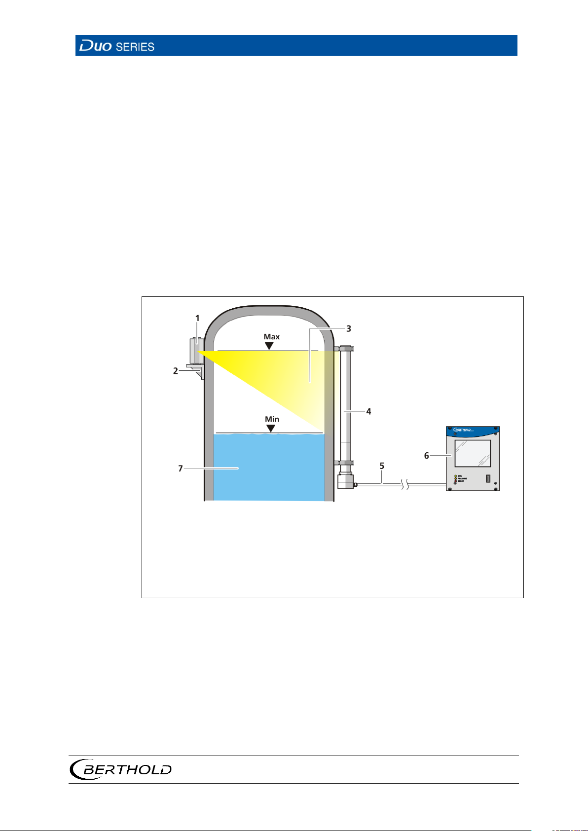
Fig.
3 System Description
3.1 Measuring Principle
The detectors of the DuoSeries are used in industrial measuring systems for measuring the level, density or mass flow in different installation situations. In addition
to the detectors of DuoSeries, additional system components such as transmitters,
radioactive sources and shieldings are required for a complete measuring system.
Usage of these system components is not subject of this operating manual. Please
refer to the individual manuals of the respective system components.
The detectors of the DuoSeries supply measurement signals for further processing
and visualisation of LB 47x or LB 44x transmitters. Each detector is connected to
either an LB 47x/44x transmitter or a 47x slave module.
1
2
3
4
5
6
7
56926BA2, Rev. 02, 04/2019
Point source shield
Mounting socket
Radiation beam
Rod detector
Measurement line to master EVU
Master EVU
Product
1 Exemplary measuring arrangement
Page 20

3 System Description
LB 4700
16
3.2 Storage
Keep devices in a dry (no condensation), dark (no direct sunlight), clean and lockable room. Stay within the temperature range for storage.
56926BA2, Rev. 02, 04/2019
Page 21
LB 4700
3 System Description
17
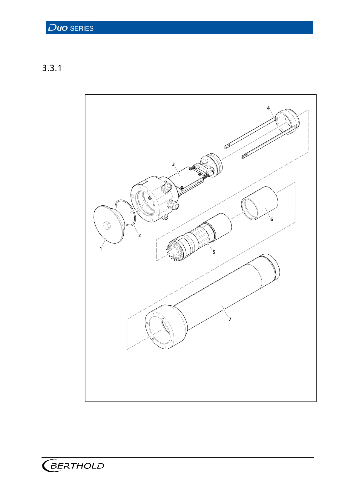
1
7
Screw lid
Stainless steel housing (housing tube)
Fig.
3.3 System Components
Overview XP variant (Class/Division)
The detectors XP variant (Class/Division) consist of the following components.
2
Sealing
3
Base unit with detector electronics
4
Photomultiplier holder
5
Photomultiplier
6
Scintillator
2 View of the DuoSeries detectors XP variant (Class / Division)
Not visible on the view are the optional water cooling system and collimator.
56926BA2, Rev. 02, 04/2019
Page 22
3 System Description
LB 4700
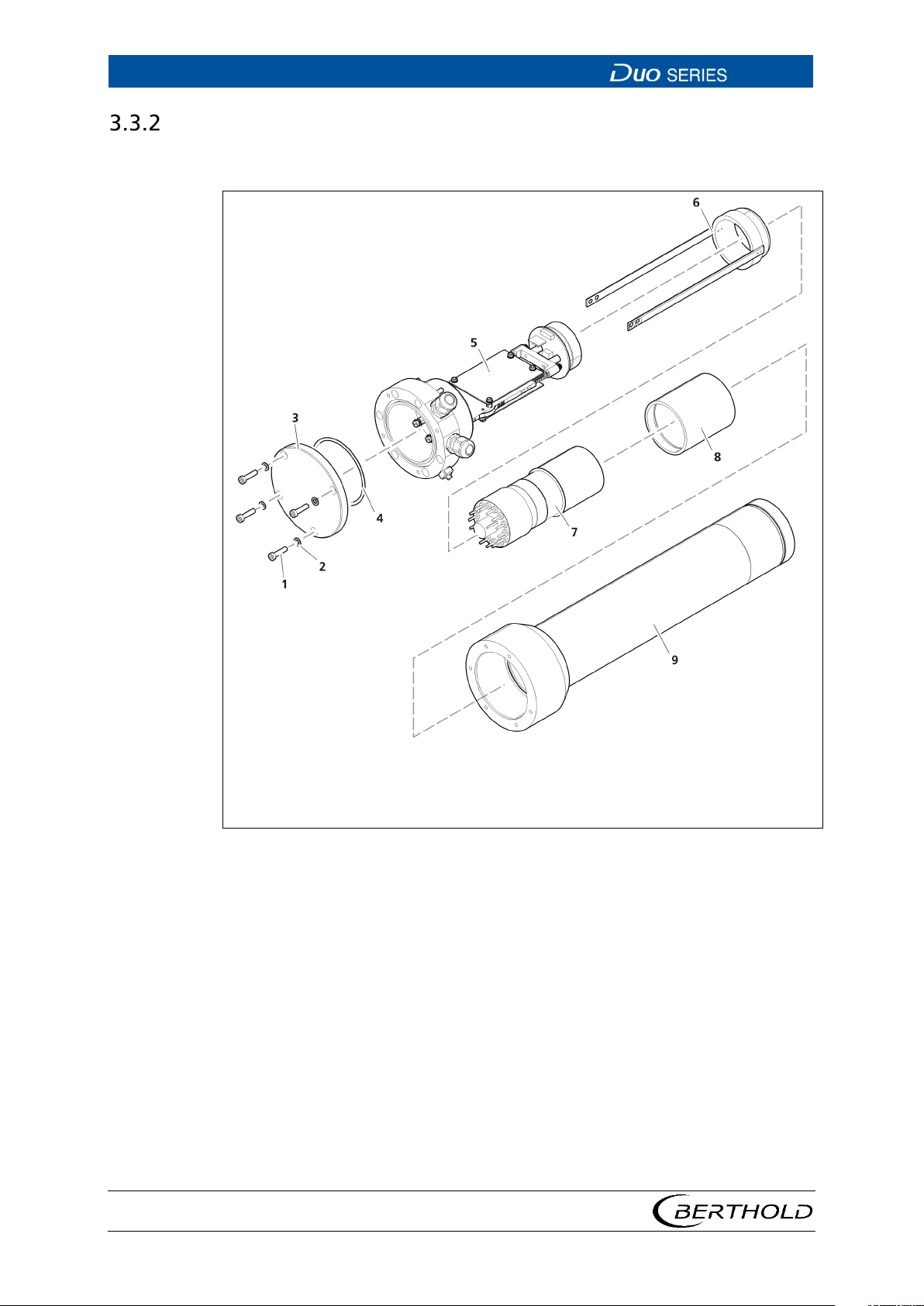
18
1
5
Screws cover
Socket unit with detector electronics
6
Photomultiplier holder
tube)
Fig.
Overview ATEX/IECEx variant
The detectors consist of the following components.
56926BA2, Rev. 02, 04/2019
2
spring washers
3
Cover
4
Sealing
7
photomultiplier
8
scintillator
9
Stainless steel housing (housing
3 View of DuoSeries detectors (ATEX / IECEx variant)
Not visible on the view are the optional water cooling system and collimator.
Page 23
LB 4700
3 System Description
19
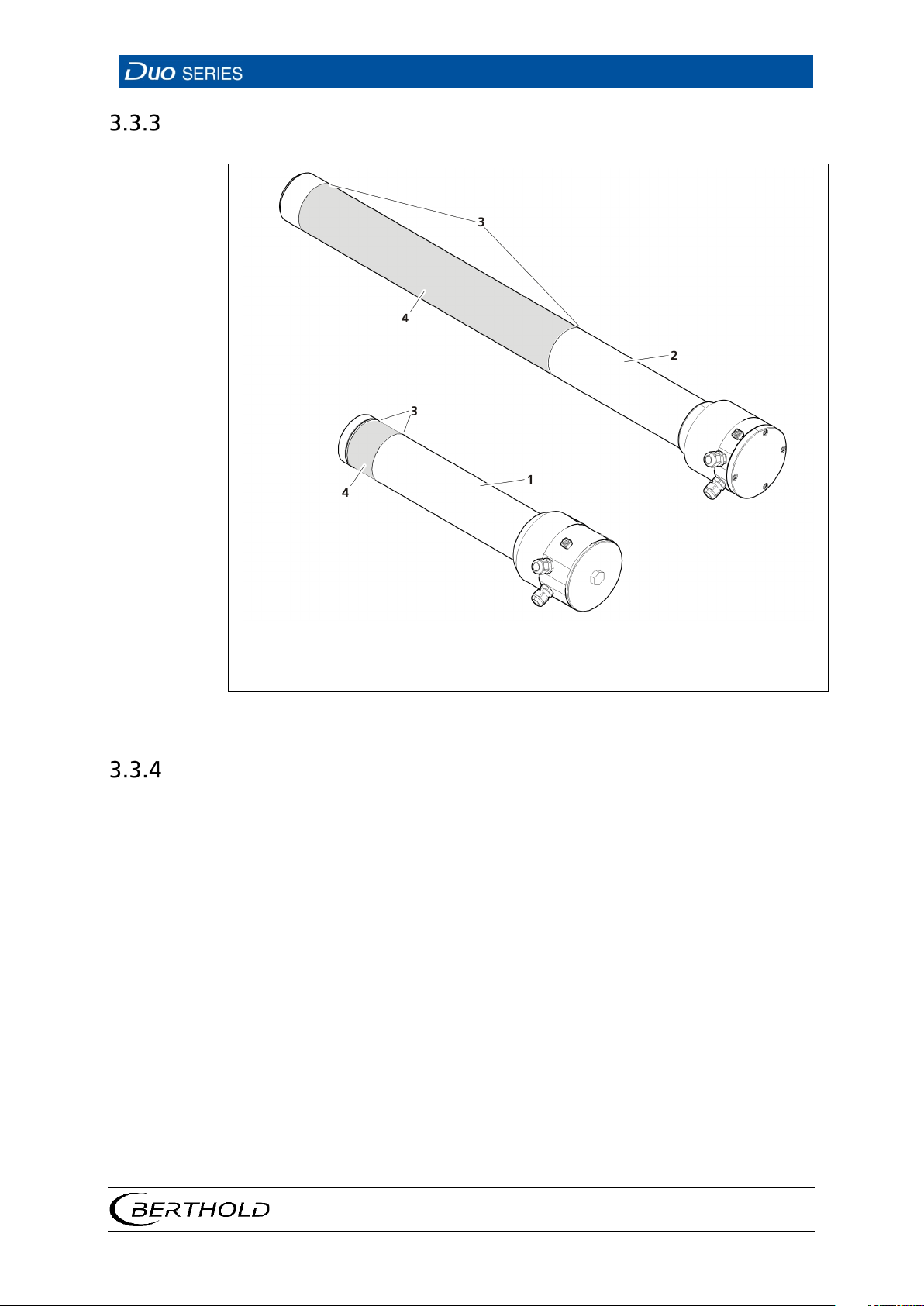
1
4
Rod detector
Sensitive area
Fig.
Rod and point detector
2
Point detector
3
Marking grooves
4 View of the DuoSeries detectors
Scintillator
The DuoSeries detectors differ in their external dimensions and the scintillators
used. Point detectors are equipped either with a 50/50 (diameter x length) NaI scintillator or a 50/60 polymer scintillator. Polymer scintillators are used in the rod detectors (models are available with the sensitive lengths of 500 mm, 1000 mm, 1500
mm and 2000 mm). The size of the scintillator determines the size of the sensitive
area (the area that is used for the measurement). Marking grooves (Fig. 3) on the
detector housing mark size and position of the sensitive area.
56926BA2, Rev. 02, 04/2019
Page 24
3 System Description
LB 4700
20
Software Version LB 4700
Release
Date
Display in LB
47xx-Systems
Significant changes
Error message on LB 44x
Faults are reported to LB
Software
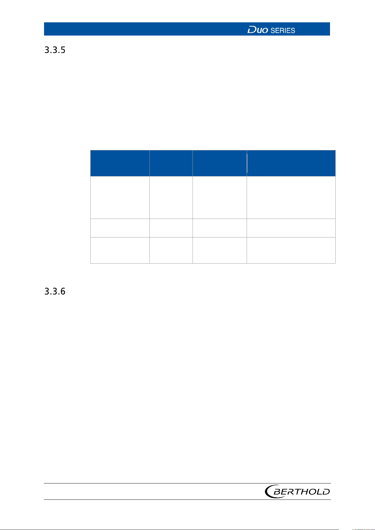
The DuoSeries detectors are distributed with software already installed.
For the revision level (version) of the software, refer to the submenu of the evaluation unit software (Device settings | Setup | Sensors | [NAME DETECTOR] | Detector
Service | Device information) or the PC software (see chap. 6.4.2).
The software as of version 12.00.00 is described in this operating manual. A software update is performed with the detector service modem (see chap. 8.2).
Change Log
12.06.09 12/2015 1.13 §
eliminated after restart
§
44x with 1V HV
12.06.10 02/2016 1.14 RID possible with LB 44x
12.06.11 03/2017 1.15 HV error is now detected on
Accessories and Options
For accessories and options for the DuoSeries detectors, see chapter 9 in these instructions.
LB 471
56926BA2, Rev. 02, 04/2019
Page 25
LB 4700
4 Installation
21
WARNING
Danger of injury by falling loads
load, keep at a safe distance.
Only use tested sling gear components appropriate for the transport weight.
Observe the marking for the centre of gravity on the outer packaging, if
WARNING
Danger to life by explosion
If the detector is located in a potentially explosive atmosphere, it is essential
to observe the corresponding instructions and safety instructions in the
CAUTION
Danger of injury caused by heavy and bulky system components
Heavy and bulky system components should only be handled using aids and
NOTICE
NOTICE
ex-
4 Installation
4.1 Safety Instructions
u Never stand underneath a lifted or suspended
u
u
applicable.
u Wear head protection and safety shoes.
u
safety manual / explosion protection manual.
u
by at least 2 persons.
u Observe the guidelines for safe handling of heavy loads.
u Ensure stability and use the provided fixing possibilities.
The applicable national regulations of the country of use have to be observed!
The detectors of the DuoSeries contain a photomultiplier with glass enclosure
and possibly a fragile scintillation crystal. Proceed carefully with the detectors
in order to prevent breakage or chipping of the photomultiplier or scintillator.
u During installation, also observe the instructions in the safety manual /
plosion protection manual.
56926BA2, Rev. 02, 04/2019
Page 26
4 Installation
LB 4700
22
NOTICE
NOTICE
NOTICE
Only clamping devices approved by BERTHOLD should be used to install the
device.
The device may only be operated if permanently installed.
For open-air installation, a weather protection cover that provides protection
against direct sunlight and associated heat should also be installed over the
detector.
4.2 Unpacking / Scope of Delivery
The product will be delivered completely configured according to the purchase order. Check your delivery for completeness and damage according to your order.
Please report missing, defective or incorrect parts immediately.
56926BA2, Rev. 02, 04/2019
Page 27
LB 4700
4 Installation
23
Fig.
4.3 Installation of Mounting Clamps
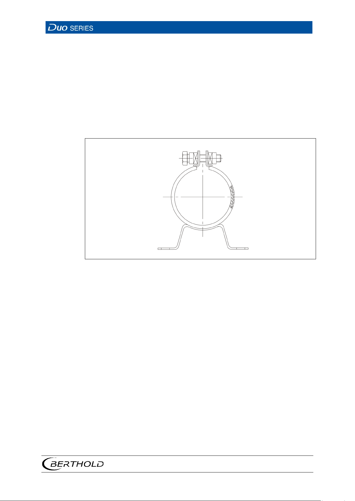
Mounting clamps are used to fasten the detectors. These clamps are installed on a
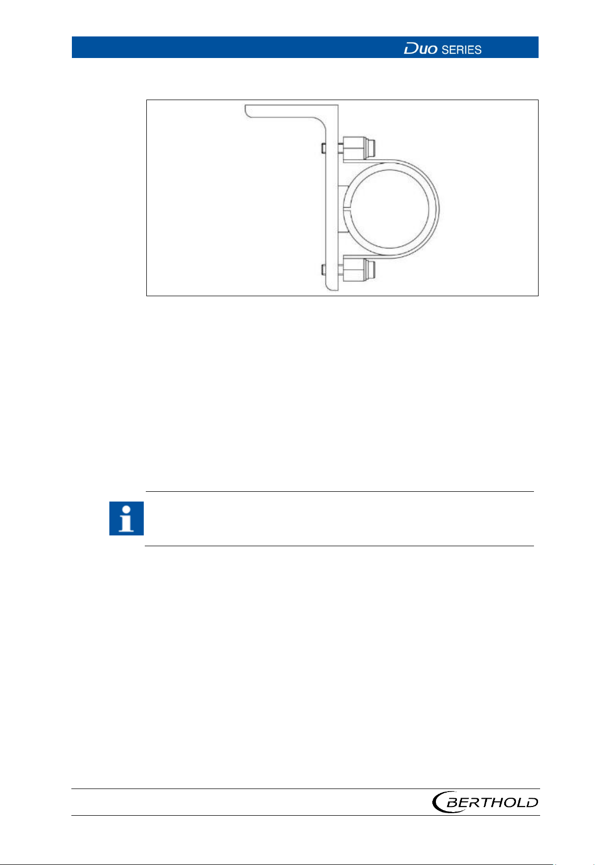
mounting base, cross beams or similar which are to be provided by the operator. A
robust stainless steel holder is optionally available for detectors with and without
water cooling system (Fig. 6). For more details, please refer to document technical
information.
These mounting clamps are suitable for point and rod detectors.
Mounting Clamps Type 1
5 Tension Clamp
1. Unscrew the screw on top of the mounting clamp.
2. Slide the clamp from the bottom over the detector housing.
3. Tighten the screw sufficiently so that the mounting clamp cannot slip on the
detector.
56926BA2, Rev. 02, 04/2019
Page 28
4 Installation
LB 4700
24
Fig.
IMPORTANT
Mounting Clamps Type 2 and Detector Holder
6 U-clamp and Detector Holder Stainless Steel
1. Unscrew the two screws on the side of the mounting clamp.
2. Take off the top part of the mounting clamp.
3. If necessary, remove the spacer ring if a detector with water cooling system is
to be installed.
4. Place the detector in the bottom part of the mounting clamp
5. Refit the top part and tighten the screws until the mounting clamp can no
longer slip on the detector.
At least two mounting clamps must be used for each detector. The two clamps
have to be mounted as far apart as possible (observe the installation situation).
Neither of the two clamps may be mounted in the sensitive area of the detector
(indicated by marking grooves on the housing).
56926BA2, Rev. 02, 04/2019
Page 29
LB 4700
4 Installation
25
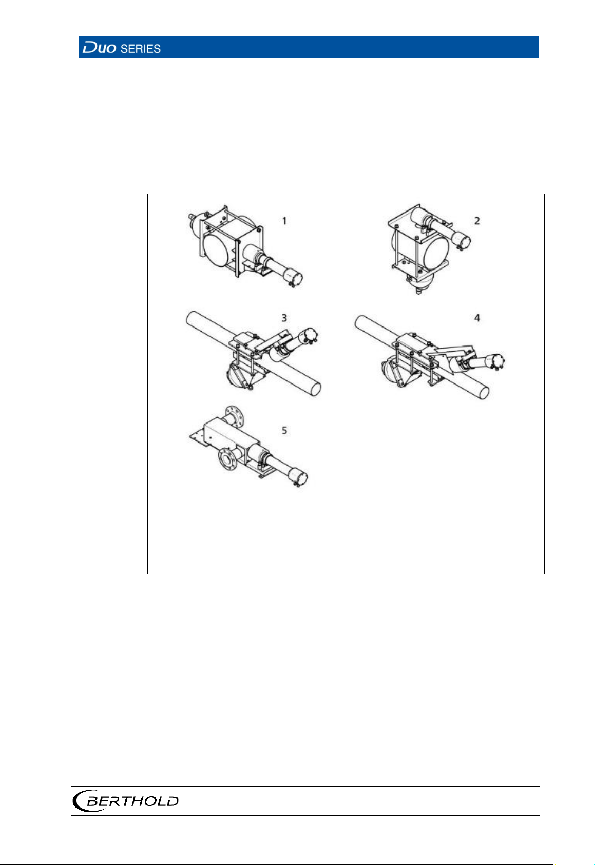
1
5
Clamping device for a radiation angle of 90° and vertical
S-shaped density measuring path
Fig.
4.4 Installation on a Pipeline
There are clamping devices for different pipe diameters and irradiation angles for
installing a detector on a pipeline. Some examples are shown in Fig. 7. For the
detailed description of the clamping devices and the associated dimension drawings, refer to the operating manual of the corresponding transmitter.
The various types of clamping devices already include mounting clamps. To mount
the detector, please follow the instructions in chapter 4.3.
detector mounting
2
Clamping device for a radiation angle of 90° and parallel
detector mounting
3
Clamping device for a radiation angle of 45°
4
Clamping device for a radiation angle of 30°
7 Overview - Pipeline Installation
56926BA2, Rev. 02, 04/2019
Page 30
4 Installation
LB 4700
26
IMPORTANT
Tip
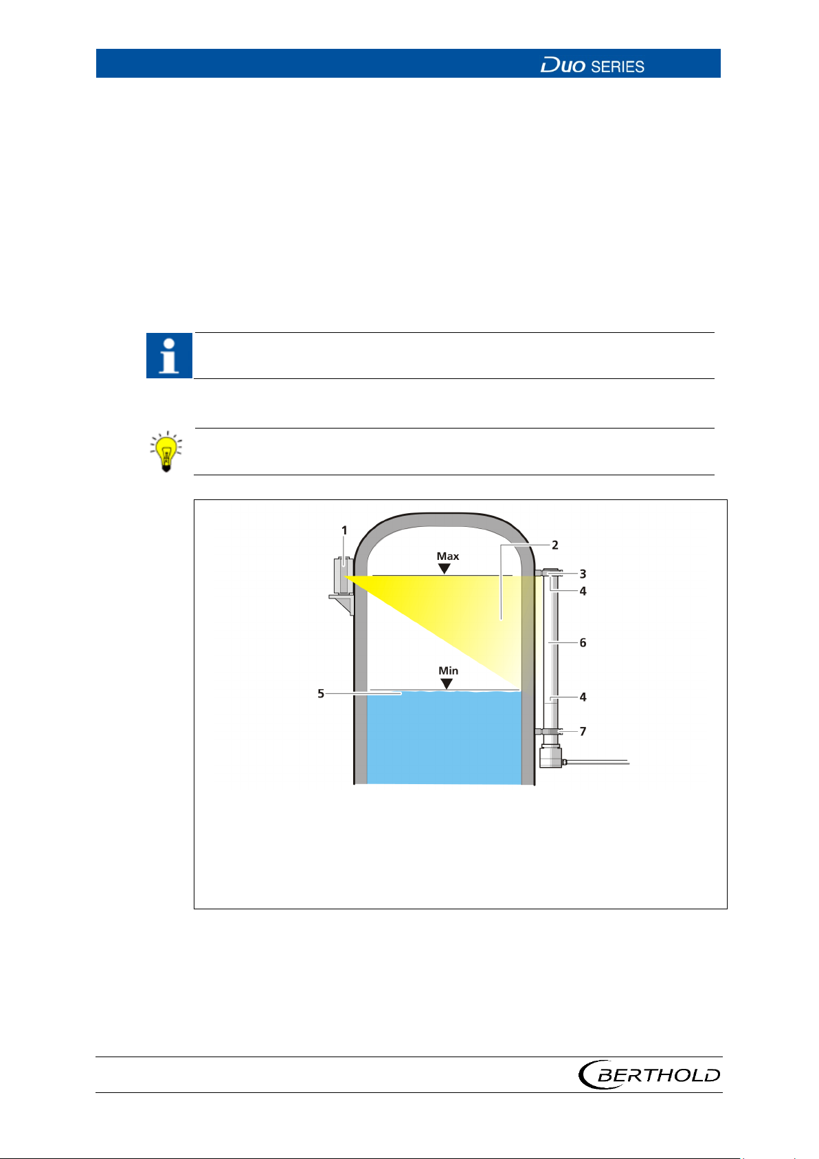
1
Point source with shielding
Fig.
4.5 Installation on a Vessel
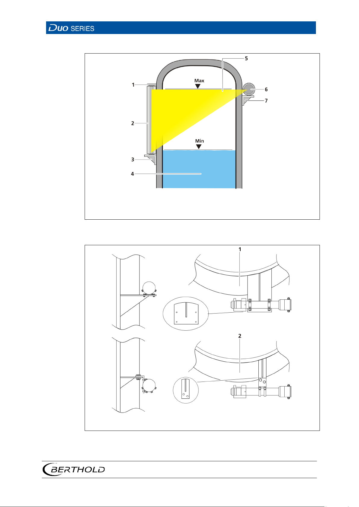
For mounting the detector on the vessel, the mounting clamps must first be
mounted on the detector (see chap. 4.3). Examples are shown in Fig. 8, Fig. 9 and
Fig. 10. Appropriate mounting fixtures (e.g. mounting brackets, platforms, etc.) are
to be provided by the operator. The dimensions of the detector and the mounting
clamps (see Appendix) should be observed. The orientation of the system components (radiator/shielding and detector) to each other and to the measuring range
is described in detail in the operating manual of the corresponding transmitter.
The cable bushing and cable inlet should be positioned so that no water can flow
along on the cable into the bushing.
The distance from the middle of the detector to the vessel surface or surface of
heat insulation should be approx. 100 mm.
Care should be taken during mounting to avoid as far as possible heat transfer
from the vessel via the clamps to the detector.
56926BA2, Rev. 02, 04/2019
2
Radiation beam
3
Upper mounting clamp
4
Marking groove on the detector
5
Level
6
Rod detector
7
Lower mounting clamp
8 Fastening of Rod Detector
Page 31
LB 4700
4 Installation
27
1
4
Holder
Level
5
Radiation beam
Fig.
1 2 Mounting with clamps
Mounting with detector holder
Fig.
2
Rod source shielding
3
Mounting base
6
Point detector
7
Mounting base
9 Fastening of Point Detector
10 Mounting of Point Detector
56926BA2, Rev. 02, 04/2019
Page 32
4 Installation
LB 4700
28
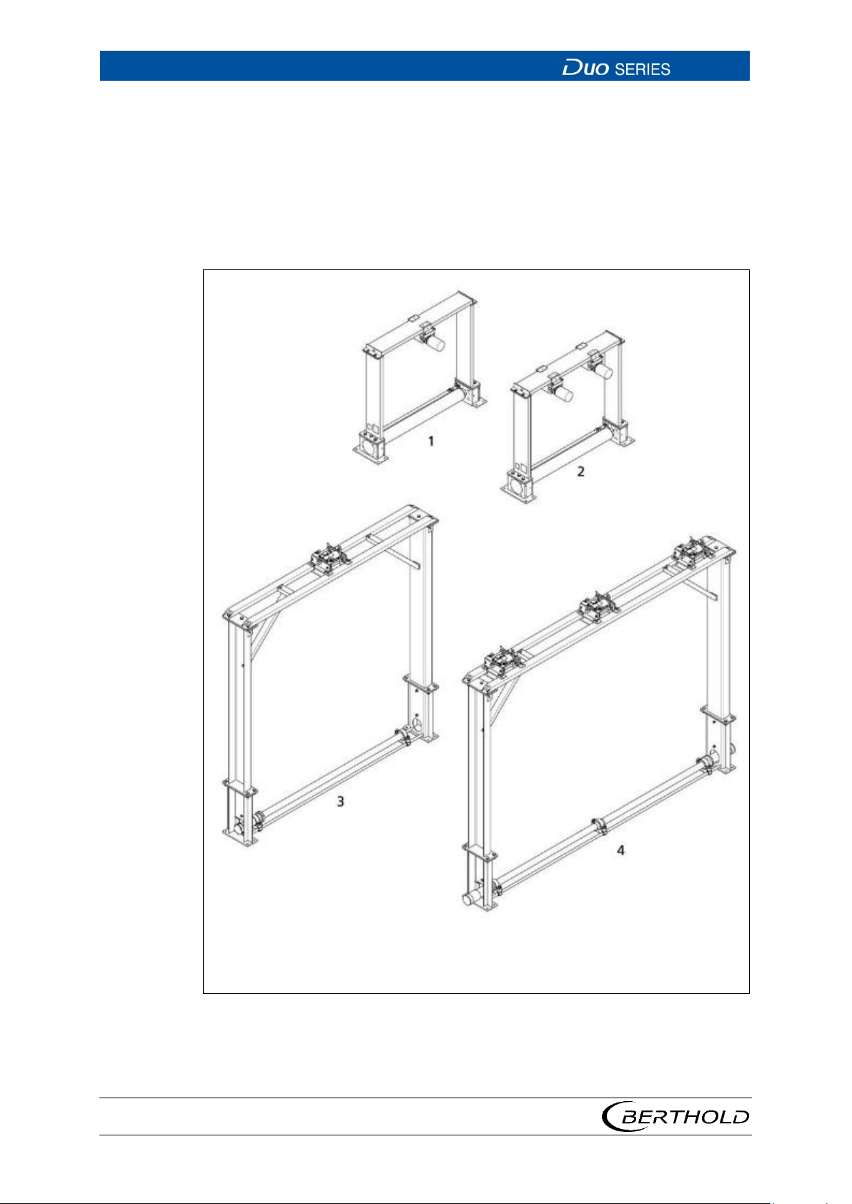
1
4
Measuring frame for one point detector
Measuring frame for two rod detectors
Fig.
4.6 Installation on a Conveyor Belt
Various measuring frames are available for the installation of detectors on conveyor belts. Some examples are shown in Fig. 11. For the detailed description of
the measuring frame and the associated dimension drawings, refer to the operating manual of the corresponding transmitter.
The measuring frames already have mounting clamps. To mount the detector,
please follow the instructions from 4.3.
2
3
56926BA2, Rev. 02, 04/2019
Measuring frame for two point detectors
Measuring frame for one rod detector
11 Overview Mounting on Conveyor Belt
Page 33
LB 4700
5 Electric Installation
29
WARNING
Danger to life by explosion
If the detector is located in a potentially explosive atmosphere, it is essential
to observe the corresponding instructions and safety instructions in the
5 Electric Installation
5.1 Initial Start-up
u
safety manual / explosion protection manual.
1. Make sure that the detector was mounted as described in chapter 4.
2. Loosen the screws on the cover and open the cover.
3. Connect the cable which connects the detector to the evaluation unit to ter-
minals 1 and 2 in the connection compartment. Also observe the operating
manual for the evaluation unit LB 47X. The screws for fixing the conductors
must be tightened with a torque of 1.2 Nm at the stud-type bushings.
4. Optional: Connect the connection cable of a Pt100 resistance thermometer
(for measuring the medium temperature) to terminals 3 and 4 in the connection compartment with a torque of 1.2 Nm.
5. If a shielded cable is used, connect the shield on terminal 5 on the connection
compartment. Make sure that the shield is sufficiently isolated from contact
with other current-carrying conductors.
6. Connect the detector to a local equipotential bonding.
7. Attach the O-ring to the groove on the face of the socket.
8. Attach the lid. For all threads fat must be used, OKS 217 is recommended. To
ensure the sealing function, the grease must be thickly applied to NPT threads.
u The cover screws (cylinder head screws ISO 4762 - M5x16-A2-70) for the
ATEX / IECEx variant must be underlaid with self-locking lock washers (NL5
SS from Nordlock®) and tightened with a torque of 4 Nm.
u The screw cap of the NEC / CEC version must be tightened on the hexagon
(spanner size SW 19) with a torque of 15 Nm.
9. Unused entries must be closed with the plugs listed (1/2 "NPT fitting) A tight-
ening torque of 20 Nm is recommended.
u The electrical installation is complete.
56926BA2, Rev. 02, 04/2019
Page 34
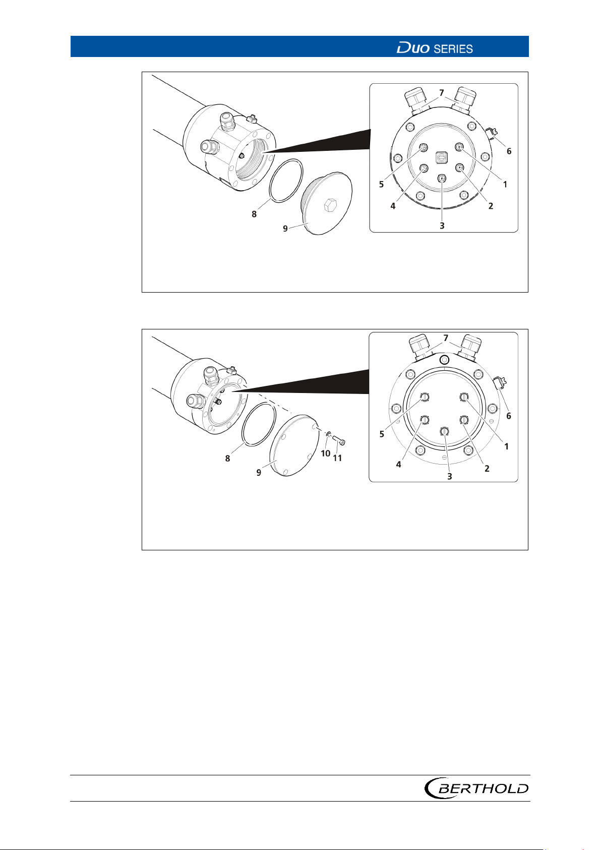
5 Electric Installation
LB 4700
30
1
5
Signal and supply circuit +
Potential equalization
6
Potential equalization
Fig.
1
6
Signal and supply circuit +
Potential equalization
7
Cable glands
Fig.
2
Signal and supply circuit -
3
Pt100 +
4
Pt100 -
7
Cable glands
8
Sealing
9
Screw cap
12 Connection compartment XP variant (Class / Division)
56926BA2, Rev. 02, 04/2019
2
Signal and supply circuit -
3
Pt100 +
4
Pt100 -
5
Potential equalization
8
Sealing
9
Cover
10
Spring washers
11
Screws cover
13 Connection compartment ATEX/IECEx variant
Page 35
LB 4700
5 Electric Installation
31
NOTICE
NOTICE
5.2 Reuse of Detectors
If a detector was previously used, then please observe the following:
Detectors that were used in non-explosive areas may no longer be used in an
explosive area.
If an intrinsically safe detector was previously used, then please observe the
following:
If intrinsically safe signals were connected to non-intrinsically safe circuits,
these may no longer be connected to intrinsically safe circuits.
56926BA2, Rev. 02, 04/2019
Page 36

5 Electric Installation
LB 4700
32
56926BA2, Rev. 02, 04/2019
Page 37

LB 4700
6 Operation
33
6 Operation
6.1 Operating Concept
For operation, different user interfaces are available
1. Evaluation unit LB 47x
2. Evaluation unit LB 44x
3. PC software (via detector service modem)
The detector internal diagnostic functions and data are not available when operating the detector with the transmitters LB 471 and LB 44x.
The operation and parameterisation is described solely by the example of the PC
software. For information on the operation of the detector with the transmitters
LB 47x and LB 44x, please refer to the respective operating manual of the transmitters.
56926BA2, Rev. 02, 04/2019
Page 38
6 Operation
LB 4700
34
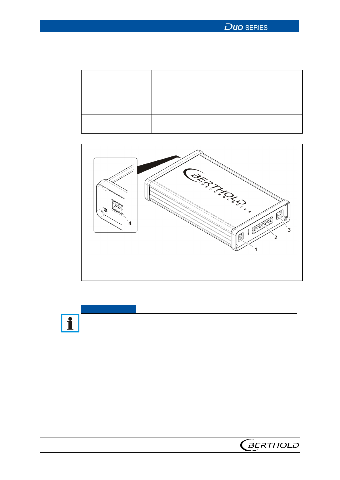
1
4
Power connection
2-pin FSK connector
Fig.
NOTICE
6.2 PC Software
The following system requirements have to be met:
System requirements Menu language: English
Connections USB port
Windows XP or higher
512 MB RAM
1 gigahertz processor
USB port
2-pin FSK interface to the detector
2
Terminal strip
3
USB port
14 Detector Service Modem
If the detector service modem is used on intrinsically safe detectors, the detector service modem with intrinsically safe FSK interface must be used.
1. Install the driver by running the driver file "BertholdRS485.exe" before con-
necting the detector service modem.
2. Execute the installation file "Setup.exe" in order to install the operating soft-
"LB 4700 PC".
ware
u Access to the detector is possible with the operating software "LB 4700
PC".
3. Connect the detector to the 2-pin FSK connector of the detector service mo-
dem (Fig. 14 item 4).
4. Connect the detector service modem via the supplied USB cable (Fig. 14 item
3) to an available USB port on your PC.
56926BA2, Rev. 02, 04/2019
Page 39
LB 4700
6 Operation
35
1
3
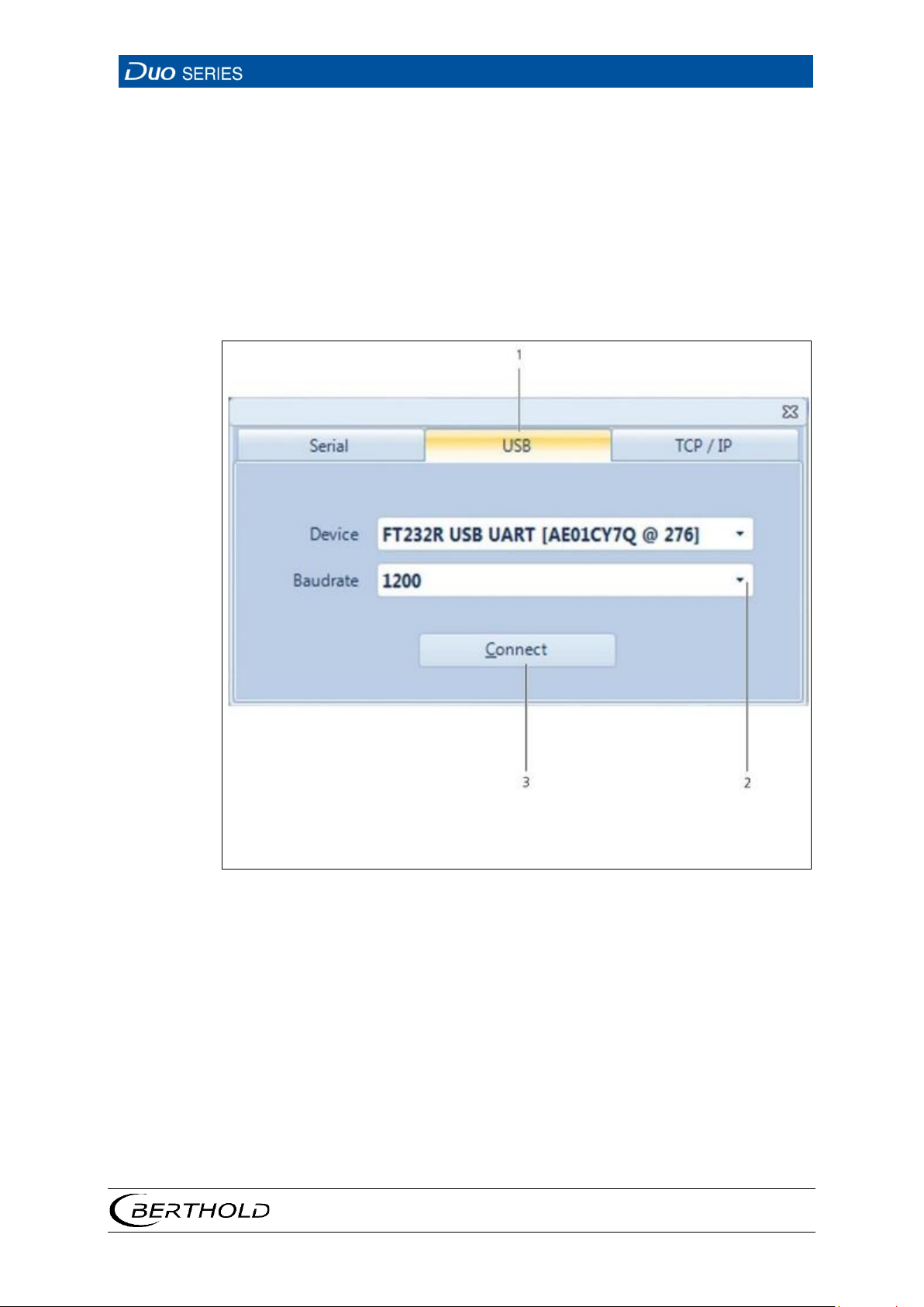
USB tab
Connect button
Fig.
5. Connect the detector service modem via the supplied power adapter to the
power supply.
6. Start the program "LB-4700 PC PC-Software.exe".
u The program opens.
7. Click on the tab <USB> (Fig. 15, item 1).
8. In the selection menu (Fig. 15, item 2), select a baud rate of 1200.
9. Click on <Connect> (Fig. 15, item 3).
u Die Startseite des Programms LB-4700 PC öffnet sich.
2
Selection of baud rate
15 Connection Window, Operating Software "LB-4700 PC"
56926BA2, Rev. 02, 04/2019
Page 40
6 Operation
LB 4700
36
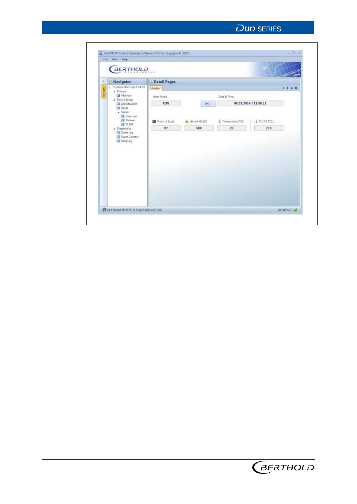
Fig.
16 Home Page, Operating Software "LB-4700 PC"
10. In order to return to the start screen from another menu, click on the tab
<Monitor>.
56926BA2, Rev. 02, 04/2019
Page 41
LB 4700
6 Operation
37
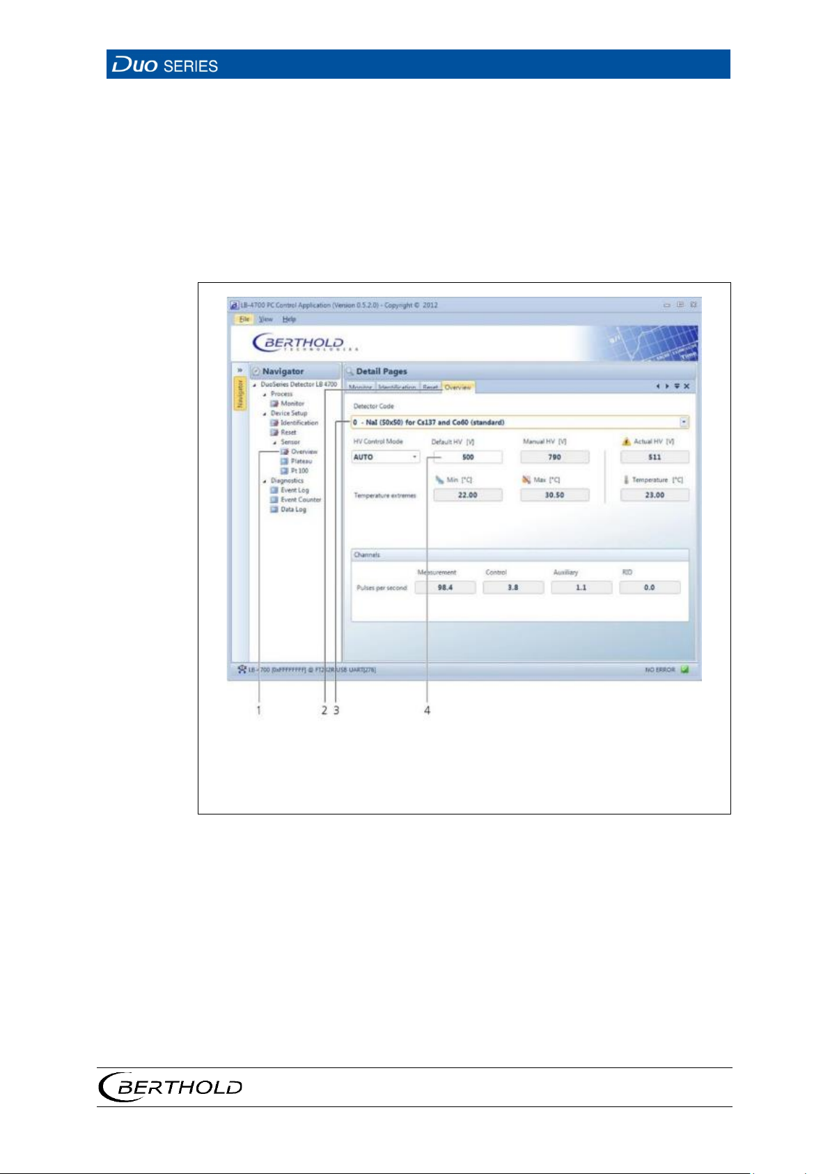
1
4
Navigator
Input field
Fig.
6.3 Operating the PC Software
The following figures show the structural design of the PC software screen and the
control options.
• Navigator with tree structure
• Input fields, buttons, and selection lists
• Tabs
2
Tab
3
Selection List
17 User Interface of the PC Software
1. Navigate in the navigator with a double click on the corresponding submenu
(Fig. 17, item 1).
2. Once opened submenus remain open and can be viewed by clicking on the
appropriate tab. (Fig. 17, item 2).
3. Open selection lists by clicking on the arrow button on the right side of the
list field (Fig. 17, item 3).
4. Click in the input field to enter the desired values (Fig. 17, item 4). A red out-
line indicates the clicked box.
56926BA2, Rev. 02, 04/2019
Page 42
6 Operation
LB 4700
38
6.4 The PC Software Menu
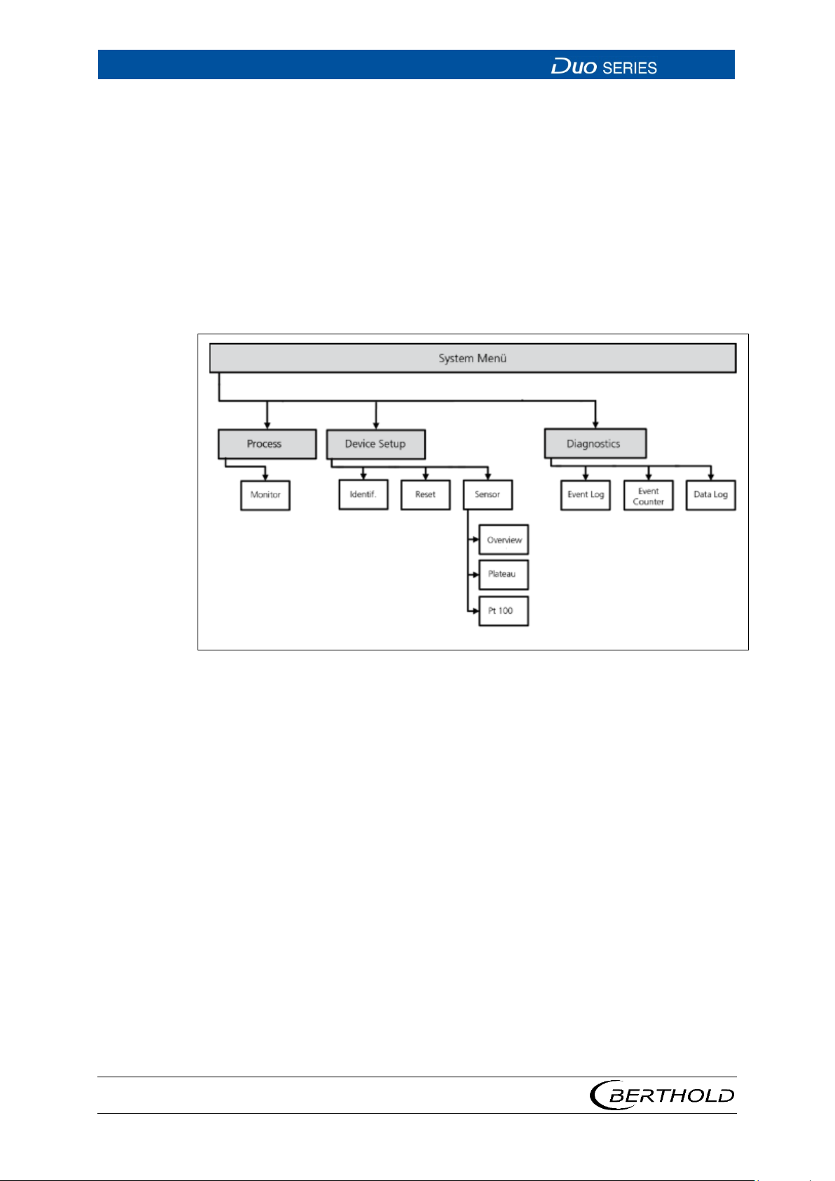
The schematic structure of the detector menu of the PC software is displayed in
Fig. 18.
• The Process menu gives you an overview of the most important measurement
data and the system status. In addition, you can also adjust the detector's internal date and time.
• In the Device Setup menu, you can read and set all system and measurement
parameters, as well as perform the plateau recording.
• The Diagnostics menu provides information about the event history and data
log.
Fig. 18 System Menu, LB-4700 PC PC-Software
56926BA2, Rev. 02, 04/2019
Page 43
LB 4700
6 Operation
39
1
7
Work Mode Display (System Status)
Date and Time Display
Fig.
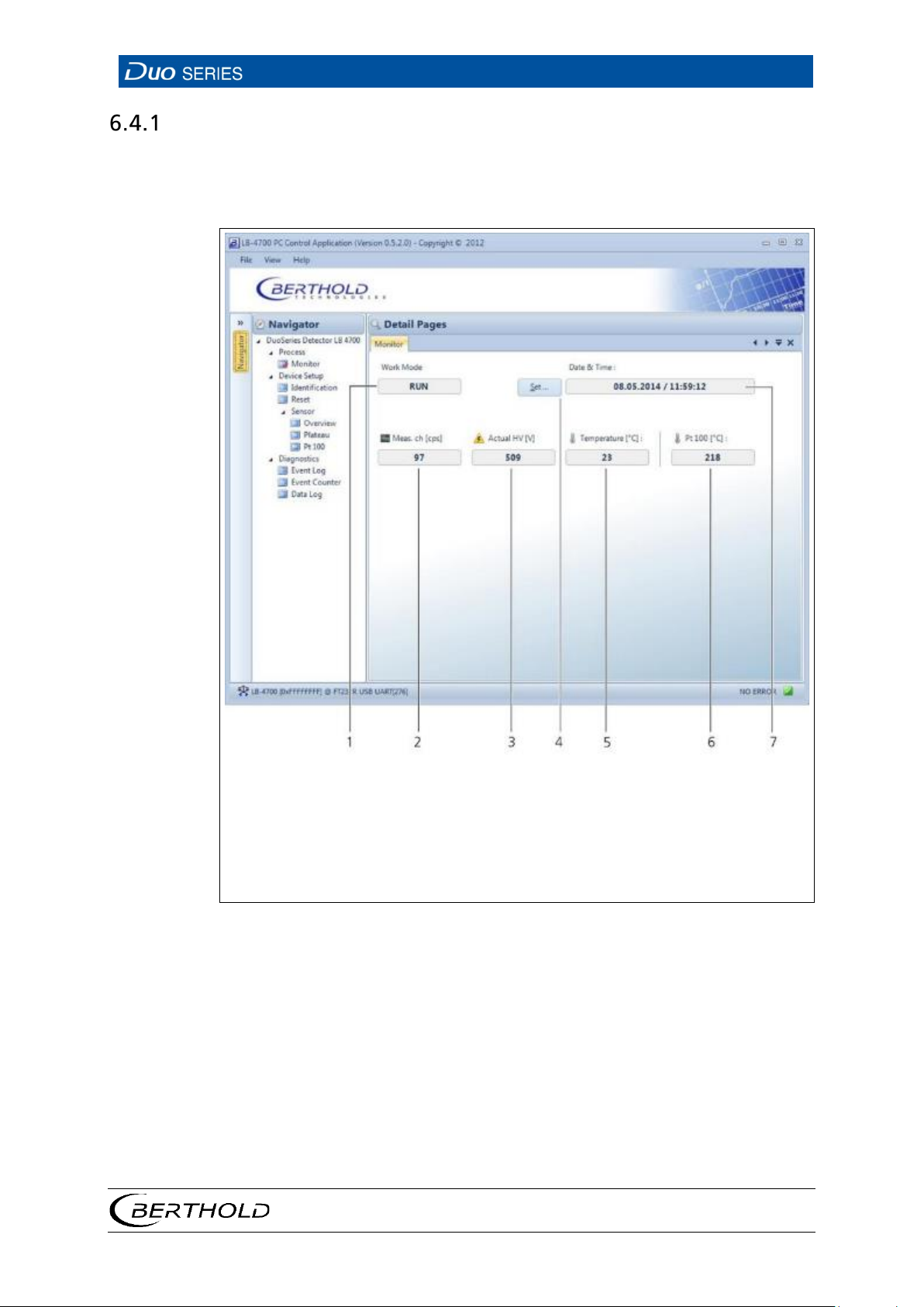
Monitor
The most important measurement data and the system status (work mode) are displayed in an overview in this submenu. In addition, you can set the date and time.
Date and time are used to date events and log data.
56926BA2, Rev. 02, 04/2019
2
3
4
5
6
Meas. Display Ch [cps] (count rate in the measuring channel)
Actual HV Display (current high voltage)
Date and Time Setting
Temperature Display
Pt 100 [°C] Display
19 Process | Monitor
Page 44
6 Operation
LB 4700
40
Fig.
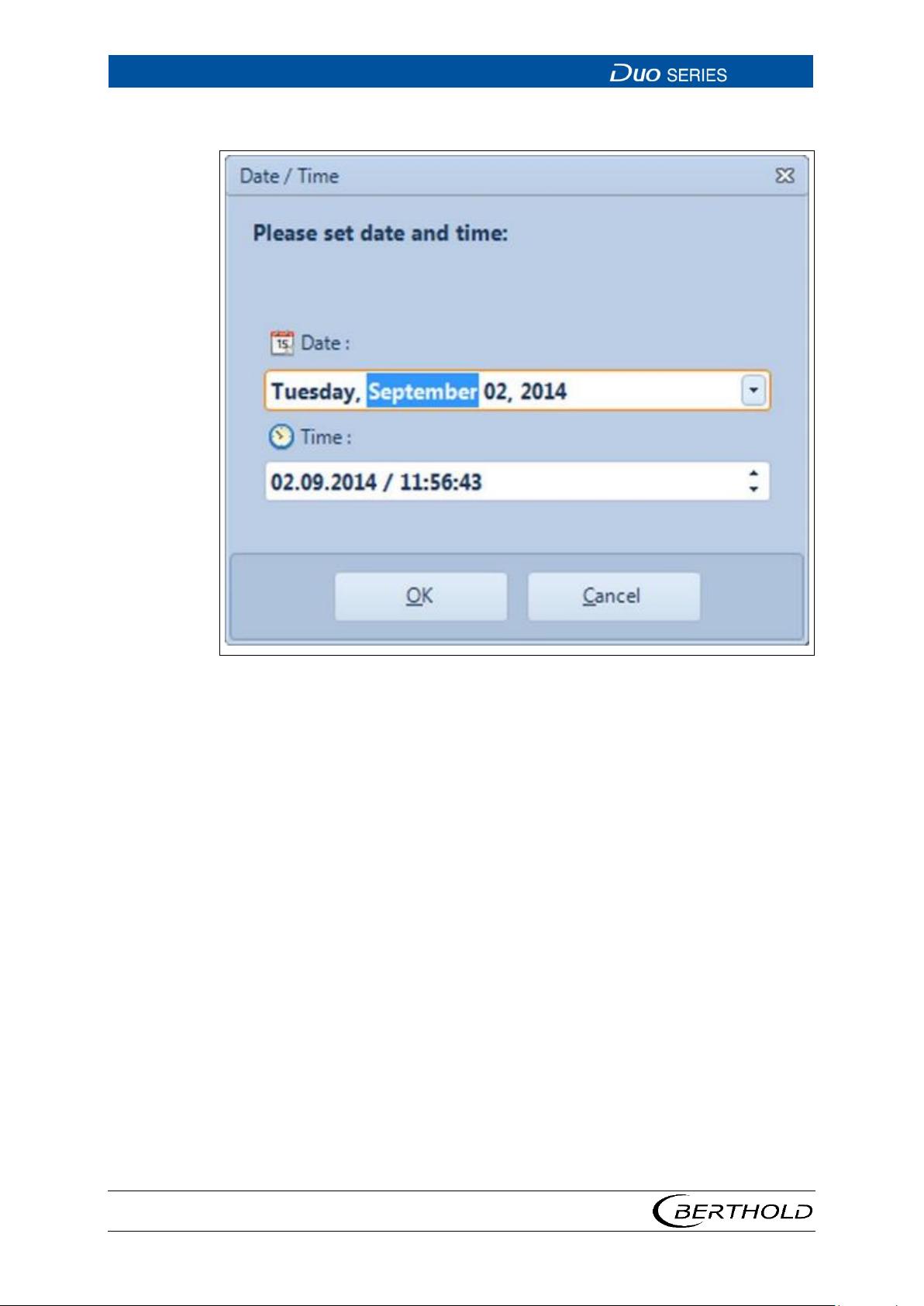
Set Date and Time
20 Window to Set the Date/Time
1. Click on the button <Set …>. (Fig. 19, item 4), to make changes to the date
and time.
u A window opens.
2. Make the changes.
3. Confirm with <OK>.
56926BA2, Rev. 02, 04/2019
Page 45
LB 4700
6 Operation
41
Fig.
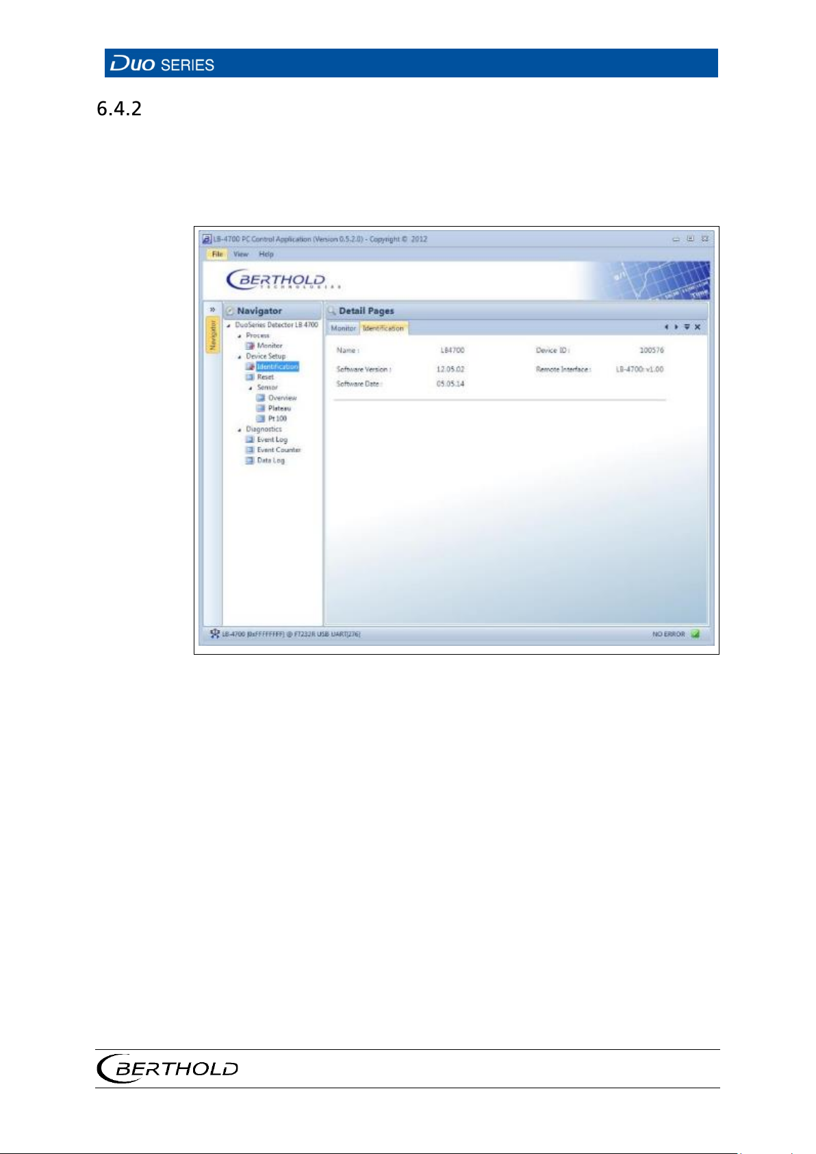
Identification
This submenu shows you an overview of the software version of the detector and
the PC program as well as the device ID.
Open the Identification submenu in the menu group
by double-clicking on
<Identification> (Fig. 21).
Device Setup of the navigator
21 Device Setup | Identification
56926BA2, Rev. 02, 04/2019
Page 46
6 Operation
LB 4700
42
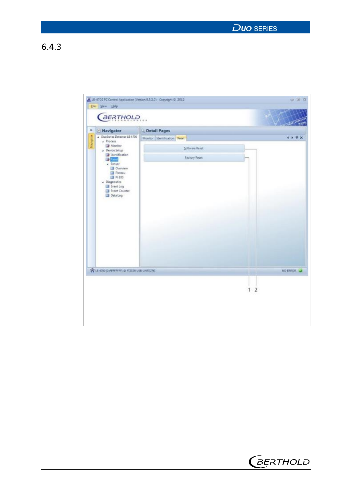
1 2 Button <Software Reset> performs a restart of the detector.
restart.
Fig.
Reset
In this submenu, you can restart the detector or reset it to the factory settings.
u Open the Reset submenu in the menu group Device Setup of the navigator
by double-clicking on
<Reset>.
Button <Factory-Reset> resets the detector to the factory settings and performs a
22 Device Setup | Reset
56926BA2, Rev. 02, 04/2019
Page 47
LB 4700
6 Operation
43
NOTICE
During the restart, the detector is not ready for measurement!
Fig.
Perform Reset and Factory Reset
All settings made, such as plateau recordings and event logs, are lost when the
detector is reset to factory settings.
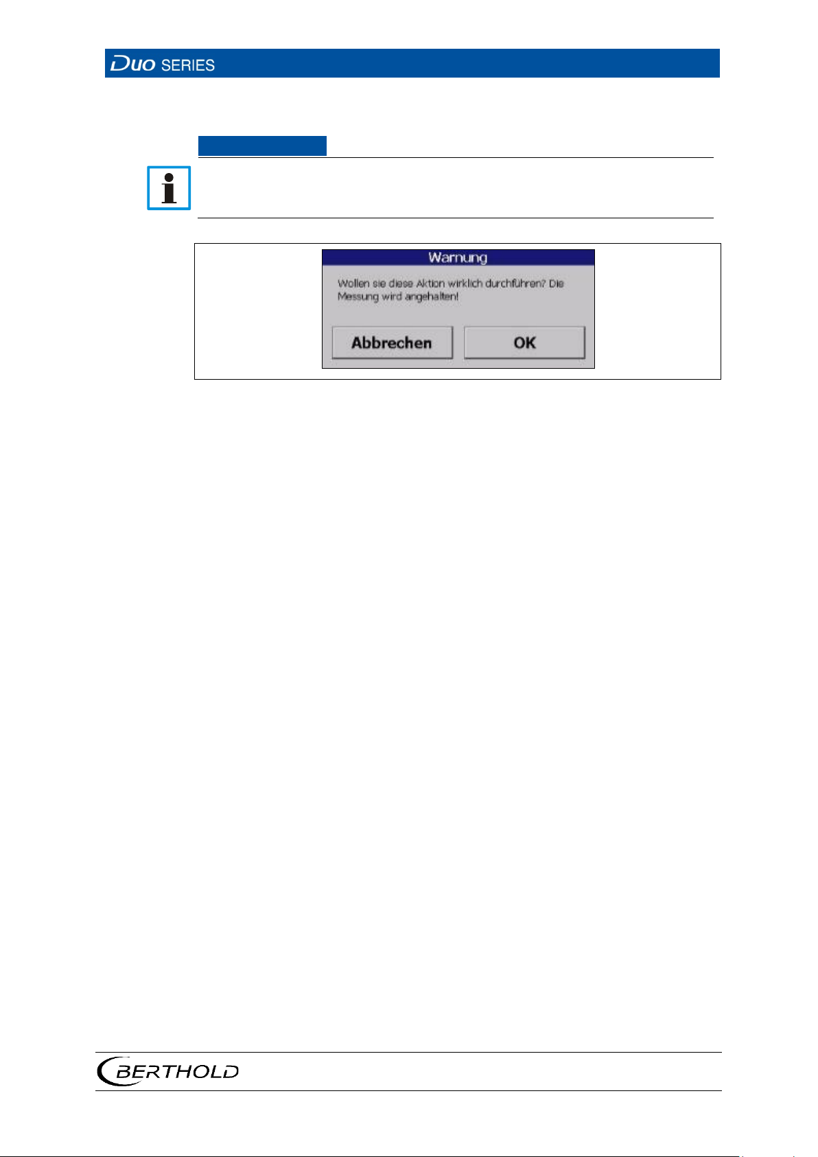
23 Warning message
1. Click on the desired Reset Button in the Reset submenu of the menu group
Device Setup .
u A warning message appears.
2. Confirm the warning message by clicking on <OK>.
u During the restart, the PC-program loses the connection to the detector for
a few seconds. The connection is automatically restored after the restart.
After restart, the detector is ready to measure again.
56926BA2, Rev. 02, 04/2019
Page 48
6 Operation
LB 4700
44
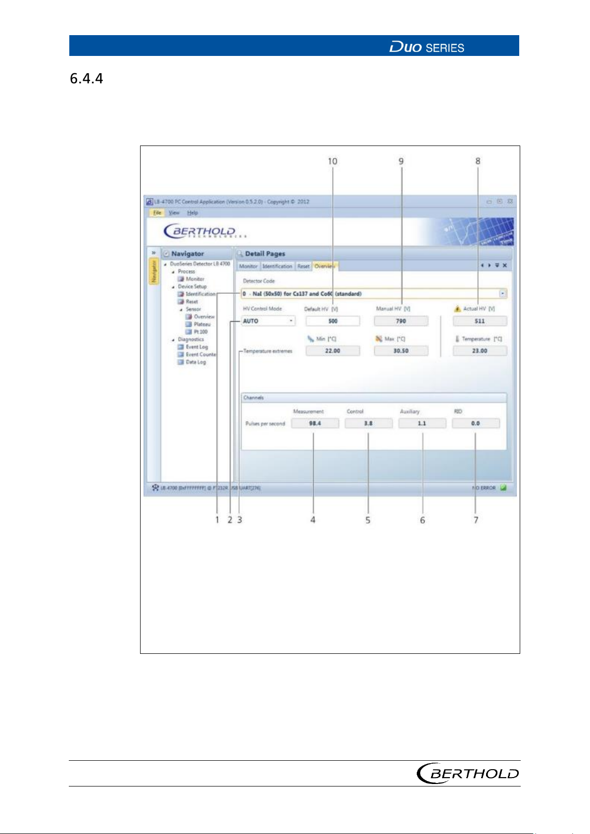
1
10
Detector code selection
Default HV (starting value of the high voltage control)
Fig.
Overview
Open the submenu Overview in the menu group Device Setup | Sensor of the navigator by double-clicking on <
and set preferences for high voltage control here.
Overview> (Fig. 24). You can select the detector code
2
High-voltage mode selection Manual/Auto
3
Temperature values display
4
Display count rate in the measuring channel
5
Display count rate in the control channel
6
Display count rate in the auxiliary channel
7
Display count rate in the RID channel
8
Display current high voltage
9
Manual high voltage
24 Device Setup | Sensor | Overview
56926BA2, Rev. 02, 04/2019
Page 49
LB 4700
6 Operation
45
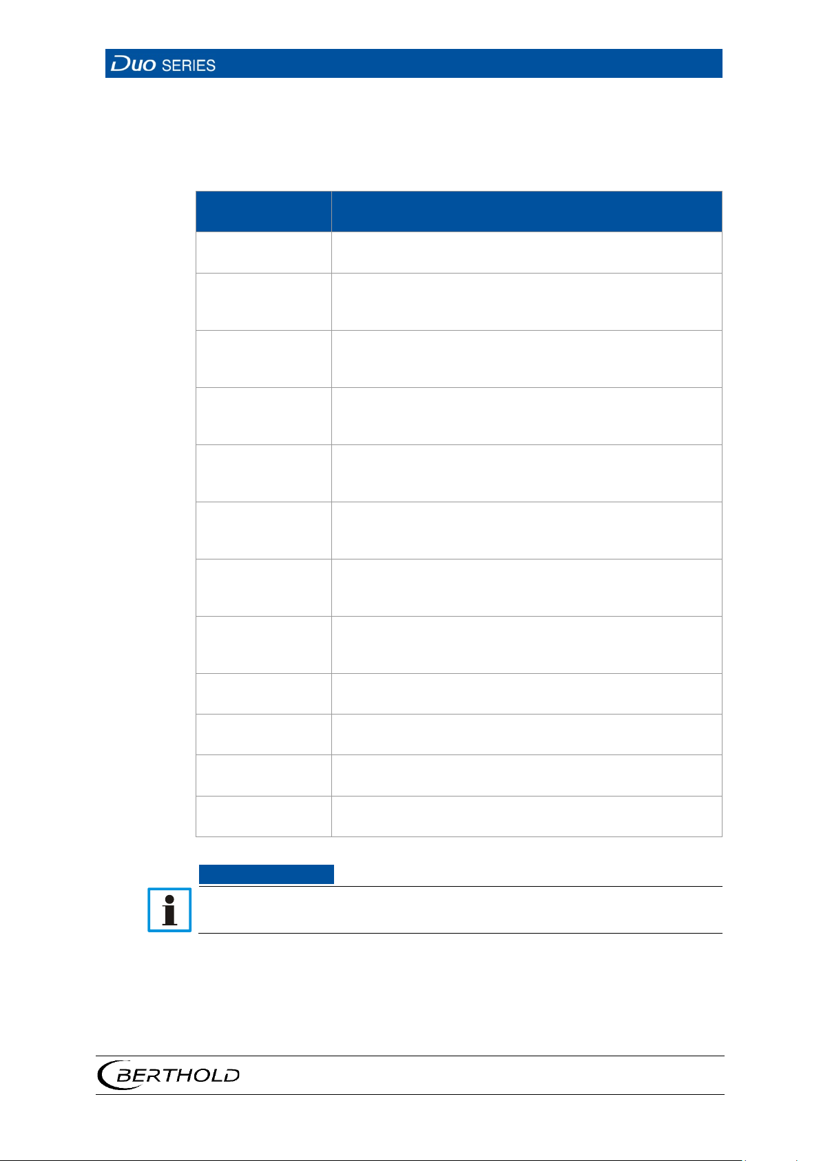
Detector code
Scintillator type and size
NOTICE
Setting the Detector Code
Internal device parameters are adjusted to suit the used scintillator size by setting
the detector code. The correct detector code is set at the factory and a change is
not normally required. A table with the detector codes to be used is found below:
0 NaI (50x50 / 40x35)
2 NaI (44x5) Am-241
(Soft Vers. >/=12.06.12)
3 NaI (44x5) Cm-244, 0 ... 60°C, high stability
(Soft Vers. >/=12.06.12)
4 NaI (44x5) Cm-244, -40 ... 60°C
(Soft Vers. >/=12.06.12)
6 Polymer (50x60)
[valid for LB 44x and LB 47x]
7 NaI (125x50) K2O/KCL, 0 ... 60°C, high stability
(Soft Vers. >/=12.06.12)
8 NaI (50x50 / 40x35) low background
(Soft Vers. >/=12.06.12)
9 NaI (125x50) K2O/KCL, -40 ... 60°C
(Soft Vers. >/=12.06.12)
52 Polymer (50x60) [valid for LB 47x]
10 Polymer (1500 mm and 2000 mm)
13 Polymer (1000 mm and 1250 mm)
22 Polymer (500 mm and 750 mm)
An incorrect setting may have a negative impact on the long-term stability of
the device or may lead to other forms of malfunction.
56926BA2, Rev. 02, 04/2019
Page 50
6 Operation
LB 4700
46
Fig.
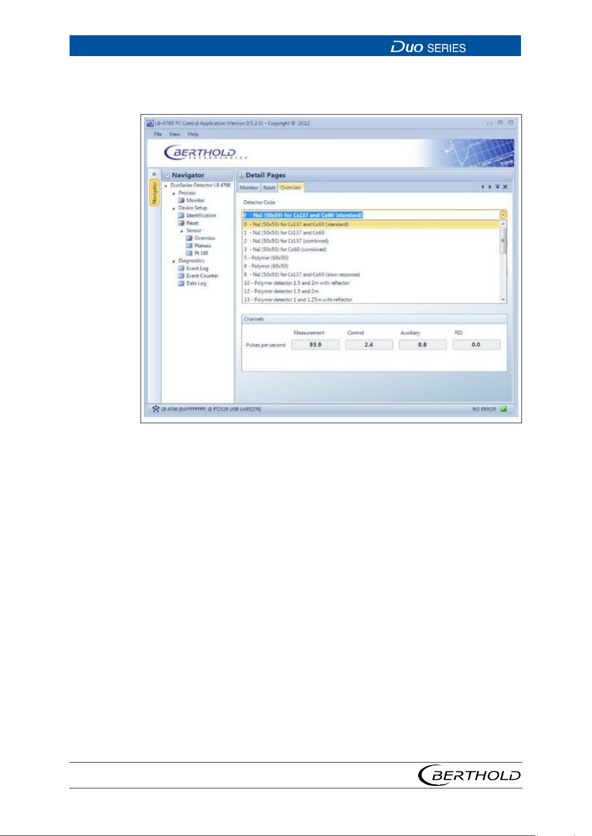
Setting the Detector Code (continued)
Click on the arrow button (Fig. 24, item 1) in order to set the desired detector code.
25 Device Setup | Sensor | Overview | Detector Code
56926BA2, Rev. 02, 04/2019
Page 51
LB 4700
6 Operation
47
AUTO
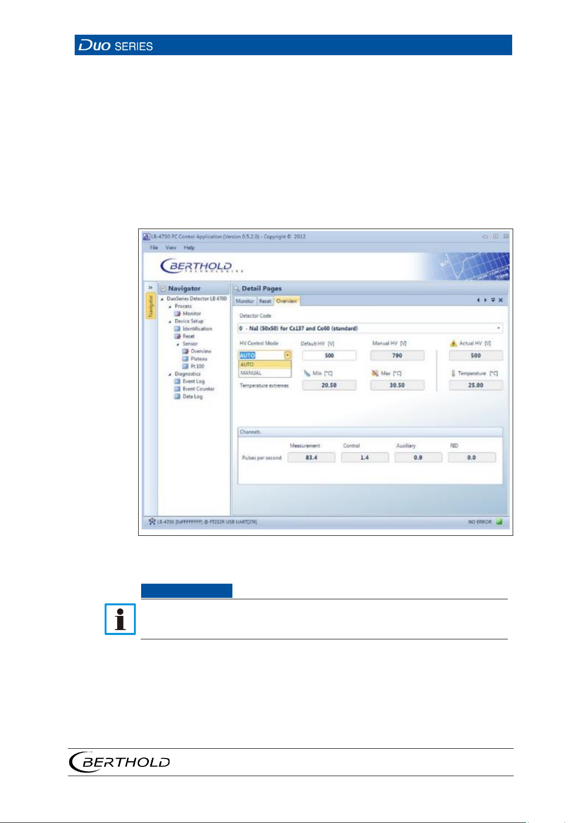
The optimum high-voltage supply of the photomultiplier is
MANUAL
The high voltage is maintained at a fixed, user-entered
Fig.
NOTICE
Setting the High Voltage Control
Click on the selection arrow (Fig. 24, item 2) in order to set the desired HV mode
(auto or manual).
automatically determined and set by the device
value (manual HV, Fig. 24, item 9).
Click in the input field "Default HV" (Fig. 24, item 10) in order to enter the desired
starting value for the high voltage control.
26 Device Setup | Sensor | Overview | HV Control Mode
Default HV is preset by BERTHOLD. A subsequent change is not usually necessary. The default value HV = 0 may only be set for testing purposes. An incorrect
setting may cause malfunction.
56926BA2, Rev. 02, 04/2019
Page 52
6 Operation
LB 4700
48
1
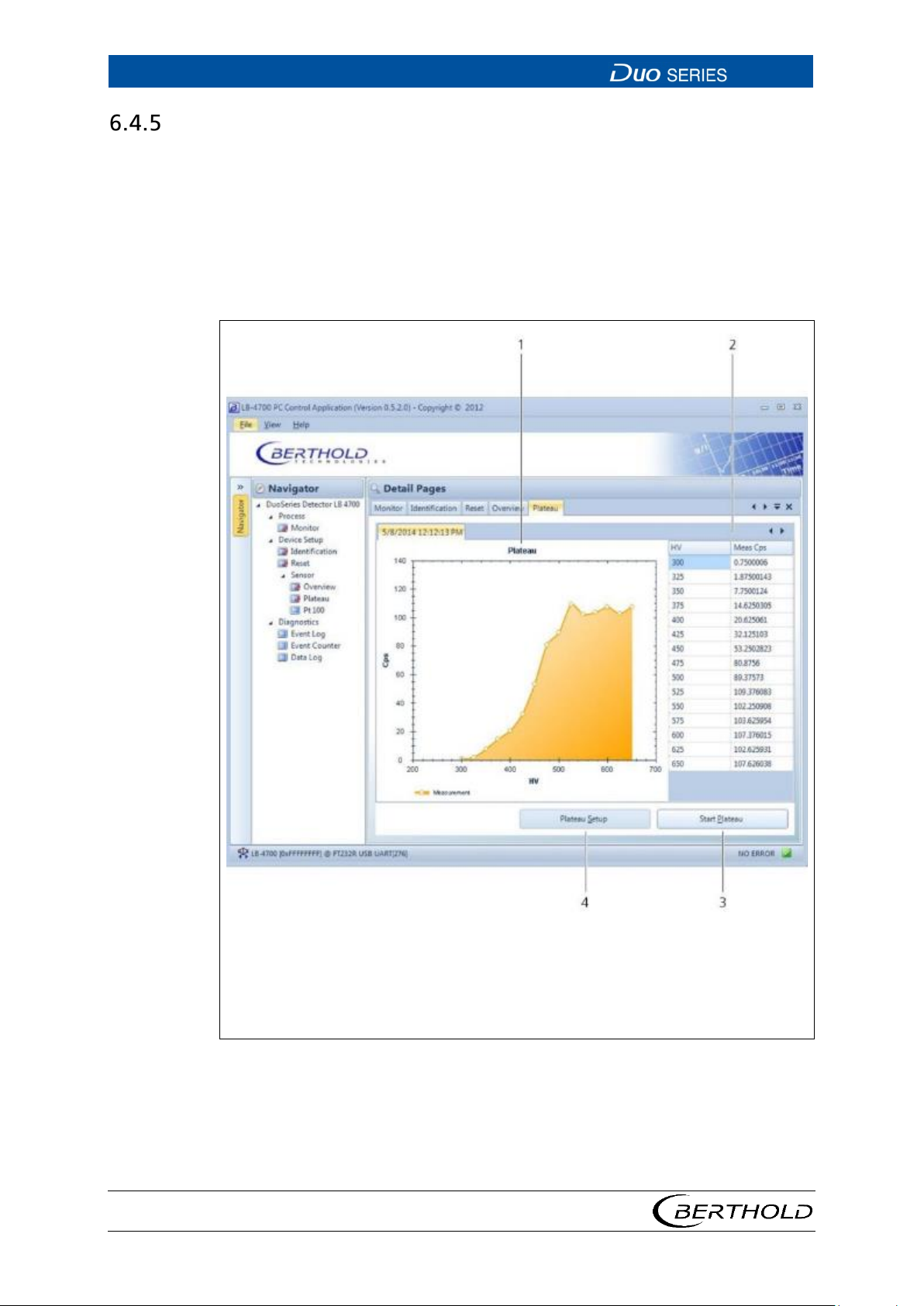
Display of the plateau curve
Fig.
Plateau
Open the submenu Plateau in the menu group Device Setup | Sensor of the navigator by double-clicking on
Here you can read the saved plateau curve on the detector, set the parameters for
plateau recording, and perform the plateau recording by clicking on
eau> .
The plateau curve is used for diagnostic purposes and must not be recorded during
normal operation.
<Plateau> (Fig. 27).
<Start Plat-
56926BA2, Rev. 02, 04/2019
2
3
4
Display of the high-voltage values and the corresponding measured values
of the count rate.
Button Start Plateau
Button Plateau Setup
27 Device Setup | Sensor | Plateau
Page 53
LB 4700
6 Operation
49
Fig.
Setting the Parameters for the Plateau Recording
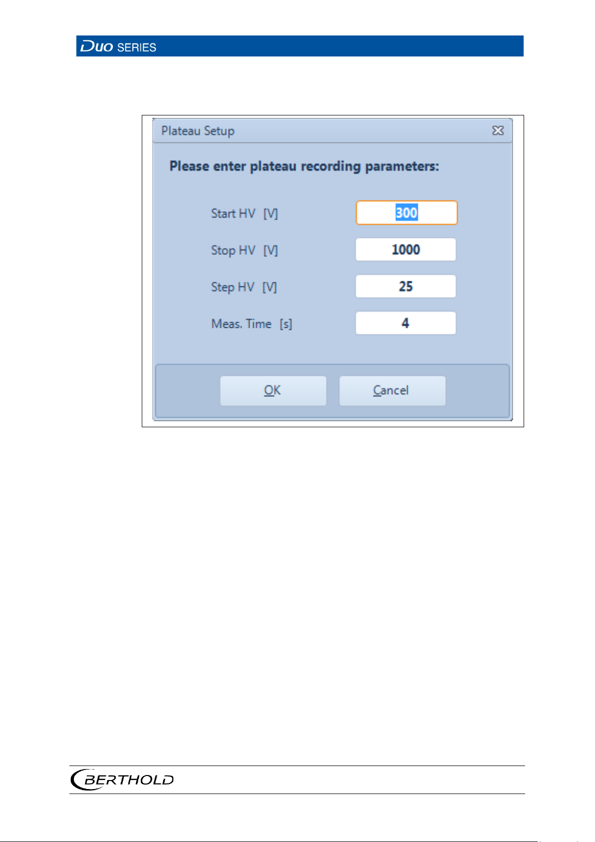
Click on <Plateau Setup> (Fig. 27, item4), in order to set the parameters.
28 Settings Dialogue Window for "Plateau Setup"
Start HV Start value of the high voltage for a plateau measurement
Stop HV End value of the high voltage for a plateau measurement
Step HV Step size between two points during plateau measurement
Meas. Time Measurement time for each plateau measurement point
56926BA2, Rev. 02, 04/2019
Page 54
6 Operation
LB 4700
50
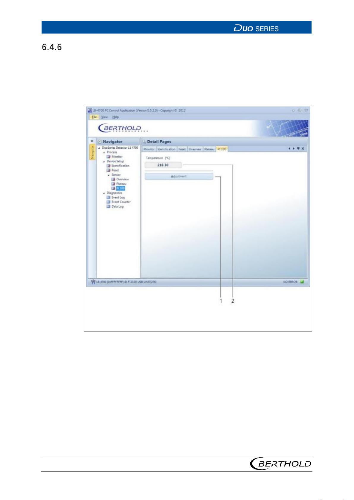
1 2 Adjustment button
Fig.
Pt 100
Open the submenu Pt 100 in the menu group Device Setup | Sensor of the navigator by double-clicking on
The current temperature of the thermometer is displayed for the associated Pt 100
thermometer in this submenu. You can also calibrate the temperature measurement.
<Pt 100>. (Fig. 29).
Temperature display
29 Device Setup | Sensor | Pt 100
56926BA2, Rev. 02, 04/2019
Page 55
LB 4700
6 Operation
51
Fig.
Fig.
Calibrate Pt 100 Temperature Measurement
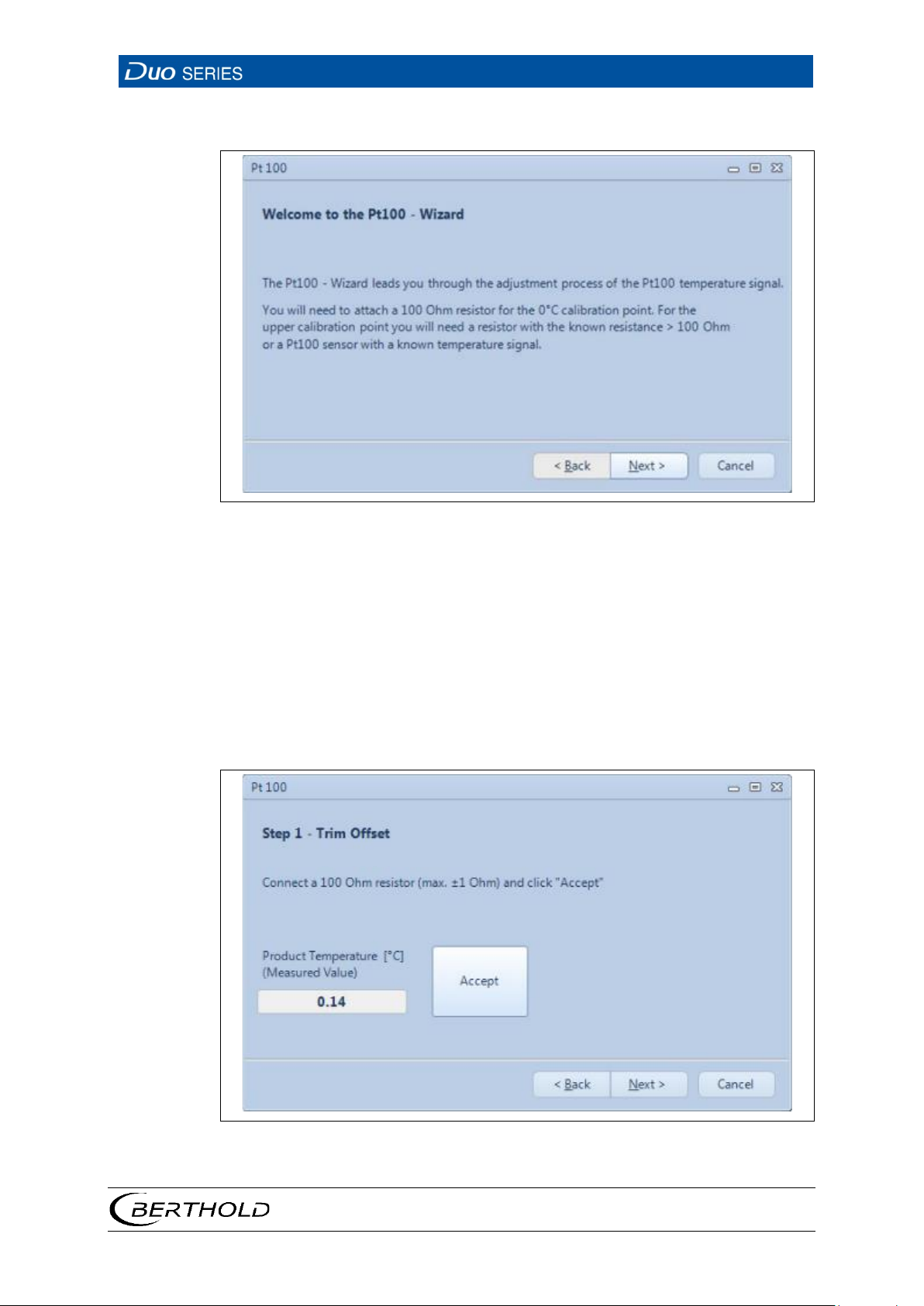
30 Start Window of the Pt100 Wizard
1. Click on the button <Adjustment> (Fig. 29, item 1) in order to calibrate the Pt
100 temperature measurement.
u A window opens. The Pt100 wizard guides you through the calibration pro-
cess.
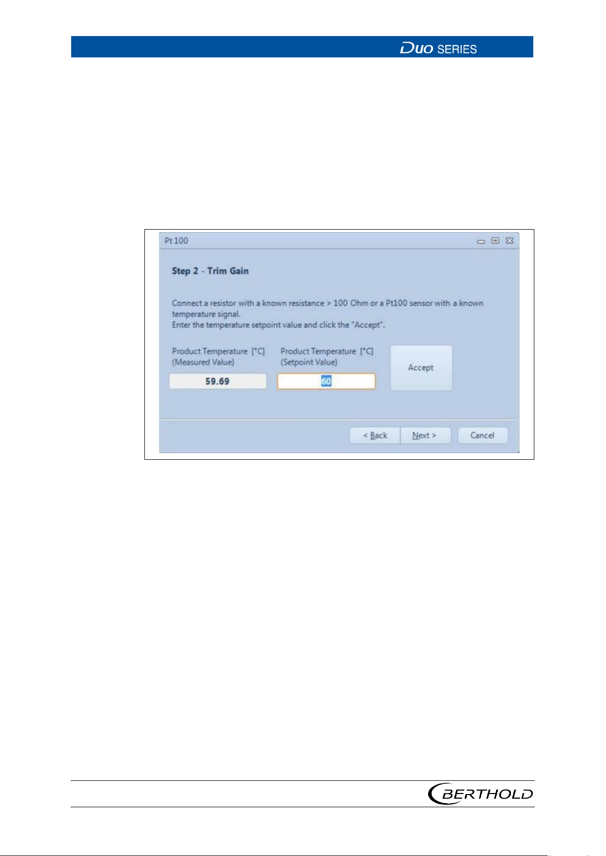
2. Connect a resistance of 100 ohms at terminals 3 and 4 in the connection com-
partment of the detector.
3. Click on <Accept> in order to calibrate the 0 °C point.
u The product temperature should now be displayed at about 0 °C.
31 Step 1 of the Pt100 Wizard
56926BA2, Rev. 02, 04/2019
Page 56
6 Operation
LB 4700
52
Fig.
4. Click on <Next> in order to proceed to the next step.
5. Connect a defined resistance (> 100 ohms) to terminals 3 and 4 in the connec-
tion compartment of the detector (see
Fehler! Verweisquelle konnte nicht
gefunden werden.) and enter the corresponding temperature value under
"Real Temperature". Alternatively, you can also use a Pt 100 sensor with a
known temperature signal. In this case, enter the known Pt 100 temperature.
6. Click on <Accept>.
u The measured product temperature should now roughly match the entered
value.
7. Click on <Next>, in order to proceed to the next step.
32 Step 2 of the Pt100 Wizard
56926BA2, Rev. 02, 04/2019
Page 57
LB 4700
6 Operation
53
Fig.
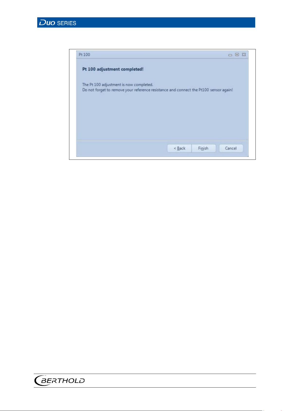
8. Click on <Finish> in order to complete the process or, if necessary, end the
process with
<Cancel> in order to cancel the calibration.
33 Last Step of the Pt100 Wizard
56926BA2, Rev. 02, 04/2019
Page 58
6 Operation
LB 4700
54
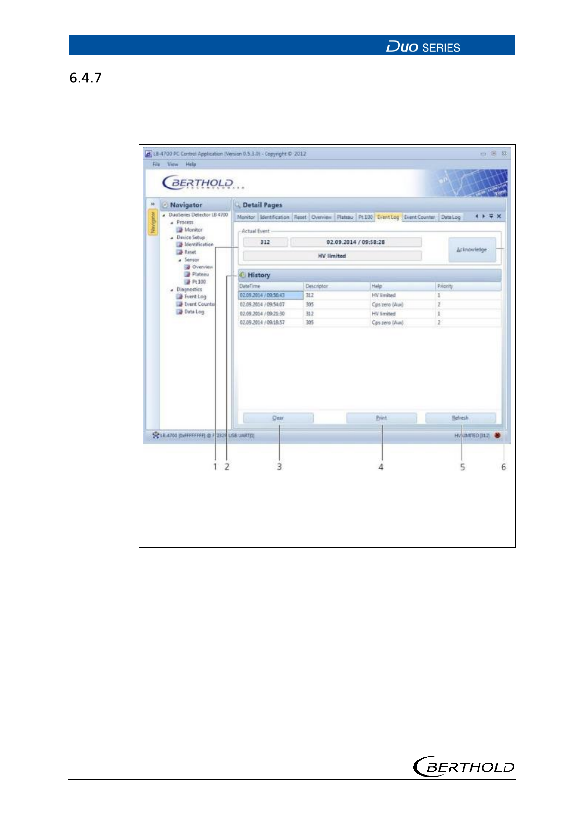
1
6
Display of the current event
Acknowledge button (acknowledges the currently pending events)
Fig.
Event Log
Open the submenu Event Log in the menu group Device Setup | Diagnostics of
the navigator by double-clicking on
Log" logs the last 25 events that have occurred with date, time and description.
<Event Log> (Fig. 34). The submenu "Event
56926BA2, Rev. 02, 04/2019
2
3
4
5
List of events occurred
Clear button (clears the event list)
Print button (creates a printable PDF)
Refresh button (reloads the current event list from the detector)
34 Diagnostics | Event Log
1. If you want to clear the event list, click <Clear> (Fig. 34, item 3).
2. In order to print the event list, click <Print> (Fig. 34, item 4).
u This will open the "Print Preview" window.
u Printing the event list using the dialogue window "Print Preview" gener-
ates a PDF.
3. Click <Refresh> (Fig. 34, item 5), in order to load the list of events from the
detector.
4. Click <Acknowledge> (Fig. 34, item 6), when an event requires an acknowl-
edgement.
Page 59
LB 4700
6 Operation
55
1
4
List of all events that have occurred
Refresh button (reloads the current event list from the detector)
Fig.
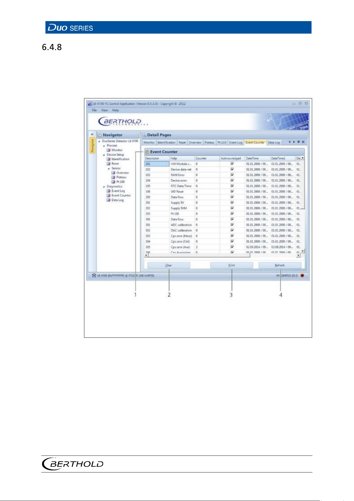
Event Counter
Open the submenu Event Counter in the menu group Device Setup | Diagnostics
of the navigator by double-clicking on
This submenu displays, sorted by groups, for each event, the counter of how often
the event occurred, and the time stamp of the last five events.
<Event Counter>. (Fig. 35).
1. If you want to clear the event list, click <Clear> (Fig. 35, item 2).
2. In order to print the event list, click <Print> (Fig. 35, item 3).
3. Click <Refresh> (Fig. 35, item 4) in order to load the list of events from the
56926BA2, Rev. 02, 04/2019
2
3
Clear button (clears the event list)
Print button (creates a printable PDF)
35 Diagnostics | Event Counter
u This will open the "Print Preview" window. Printing the event list via the
"Print Preview" generates a PDF.
detector.
Page 60
6 Operation
LB 4700
56
1
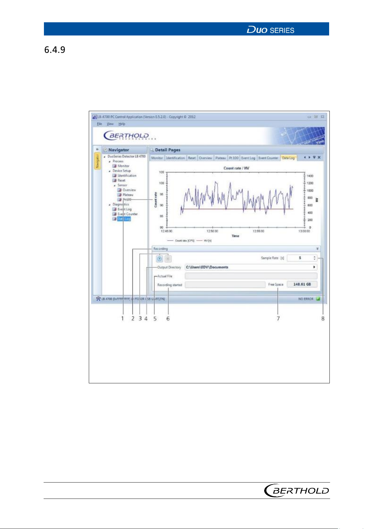
8
Graphical representation of the count rate and high voltage curve
Selection keys Sample Rate (log interval of the data logs)
Fig.
Data Log
Open the submenu Data Log in the menu group Device Setup | Diagnostics of the
navigator by double-clicking on
high voltage of the detector are shown graphically in this .
In addition, you can output the recorded chart values as a text file (.txt) and save
on the connected PC.
<Data Log> (Fig. 36). The current count rate and
2
3
4
5
6
7
Display and control panel "Recording"
Buttons to start recording and stop recording
Select output directory (output location of the log file)
Display actual file (name of the current log file)
Display recording started (date/time for the start of recording)
Display Free Space (free hard disk space on the connected PC)
36 Diagnostics | Data Log
1. To zoom, hold down the left mouse button in the chart box and highlight the
area to be zoomed.
2. Right-click in the chart box to open a window with the following settings:
o Copy: Copies the current chart view to the clipboard of PC
o Save Image as: Saves the current chart view on the PC
o Page Setup: Page settings for printing function.
o Print: Prints the current chart view.
56926BA2, Rev. 02, 04/2019
Page 61

LB 4700
6 Operation
57
o Show Point Values: Enables/disables the display of measurement
points on the chart when they are highlighted with the cursor.
o Un-Zoom: Undoes the last zoom operation.
o Undo all Zoom/Pan: Sets the zoom back to the start value.
o Set Scale to Default: Adjusts the axis scaling to the fluctuation of the
measured values.
3. In order to start the recording of log data on the PC, click on Recording |
<Record-Start> (Fig. 36, item 4).
4. In order to stop the recording, click on <Record-Stop> (Fig. 36, item 3).
5. Click on the selection arrows or click in the field <Sample Rate> (Fig. 36, item
8) in order to select or enter the log interval.
56926BA2, Rev. 02, 04/2019
Page 62

6 Operation
LB 4700
58
56926BA2, Rev. 02, 04/2019
Page 63

LB 4700
7 Troubleshooting
59
7 Troubleshooting
7.1 System Events
A list of all possible device event messages with troubleshooting options is provided below. Event messages are automatically hidden if the cause of the event is
no longer present. Exceptions are marked in the list. In this case, the event, as described in chapter 6.4.7, must be manually acknowledged.
System events can lead to the following system statuses:
• Shutdown
• Failure
• Out of Specification
• Function Check
Shutdown (Namur107: F)
A critical error has occurred. The detector will shut down to prevent damage. The
measurement is stopped.
Failure (Namur107: F)
A serious error has occurred and the accuracy of the measurement results is not
ensured. The measurement is continued.
If the detector is operated with an LB 44x/LB 471 transmitter, then the count rate
is set to 0 by the system status "Failure" in order to signal the system status. In this
case, the measurement is interrupted.
Out of Specification (Namur107: S)
The detector, one of its components or the environmental conditions are not
within the normal specifications. The measurement is continued.
Function Check (Namur107: C)
Indicates that entries are made at the detector or a function check/simulation is
being performed.
56926BA2, Rev. 02, 04/2019
Page 64

7 Troubleshooting
LB 4700
60
Code
Text
Description
Namur107
Correction
System
D101
HW
corrupted
Corrupt hardware
module
Restart the device.
BERTHOLD.
D102
Device
Permanent
was found.
Perform a factory reset and/or
contact BERTHOLD.
D103
RAM
Error in RAM.
Restart the device.
BERTHOLD.
D104
Device
error
System error
If the event occurs frequently, contact
BERTHOLD.
D105
RTC
Error in the real-
Reset the date and time.
The event must be confirmed manually.
D106
WD Reset
The watchdog
of the device.
If the event occurs frequently, contact
disturbances have triggered the event.
Main Board
D200
Data flow
Error during
of the software
Restart the device.
BERTHOLD.
D201
Supply
Hardware error
Contact BERTHOLD.
replaced.
D202
Supply -
Hardware error
Contact BERTHOLD.
replaced.
D203
Pt100
Error when
value is kept.
Restart the device.
Detector
D300
Data flow
Error during
of the software.
Restart the device.
BERTHOLD.
D301
ADC
Hardware error
Restart the device.
D302
DAC
Hardware error
Restart the device.
The event must be confirmed manually.
module
data-set
error
date/time
electronics
memory error, no
parameter set
time clock. F
has triggered
a restart
execution
F
F
F
If the event occurs frequently, contact
restart the device.
If the event occurs frequently,
If the event occurs frequently, contact
F
Restart the device.
S
F
BERTHOLD.
Verify whether massive electromagnetic
If the event occurs frequently, contact
5.0V
5.0V
Temperat
ure
calibratio
n
calibratio
n
reading the Pt100
input. The last
valid temperature
execution
F
F
The hardware is defective and, if
necessary, must be checked and
The hardware is defective and, if
necessary, must be checked and
If the event occurs frequently, contact
F
BERTHOLD.
The event must be confirmed manually.
F
S
If the event occurs frequently, contact
If the event occurs frequently, contact
BERTHOLD.
The event must be confirmed manually.
S
If the event occurs frequently, contact
BERTHOLD.
56926BA2, Rev. 02, 04/2019
Page 65

LB 4700
7 Troubleshooting
61
Code
Text
Description
Namur107
Correction
D303
Cps Zero
No count rate in
channel.
The photomultiplier may be defective.
BERTHOLD.
D304
Cps Zero
No count rate in
channel.
The photomultiplier may be defective.
BERTHOLD.
D305
Cps Zero
No count rate in
channel.
The photomultiplier may be defective.
BERTHOLD.
D306
Cps
The count rate
If the event occurs frequently, contact
D307
Threshold
The voltage of
value.
Restart the device.
D308
Threshold
The voltage of
value.
Restart the device.
D309
Threshold
The voltage of
control value.
Restart the device.
D310
Threshold
The voltage of
value.
Restart the device.
D311
HV
An error in the
was detected.
Check detector electronics and
D312
HV
The current high
more than 20%.
Check detector electronics and
D313
Lower
The average HV is
Check Default HV for plausibility and
If necessary, contact BERTHOLD.
(Meas)
(Ctrl)
(Aux)
averaging
(Meas)
(Ctrl)
the measuring
the control
the auxiliary
fluctuates more
than permissible.
the measuring
channel deviates
from the
admissible set
the control
channel deviates
from the
admissible set
F
S
S
F
Check the photomultiplier or contact
Check the photomultiplier or contact
Check the photomultiplier or contact
BERTHOLD.
If the event occurs frequently, contact
F
BERTHOLD.
If the event occurs frequently, contact
S
BERTHOLD.
(Aux)
(RID)
voltage PMT
limited
Avg. HV
limit
the auxiliary
channel deviates
more than
allowed from the
the RID channel
deviates from the
admissible set
high-voltage
supply of the
photomultiplier
voltage deviates
from the average
high voltage by
more than 20%
lower than the
Default-HV.
If the event occurs frequently, contact
S
BERTHOLD.
If the event occurs frequently, contact
S
BERTHOLD.
photomultiplier.
F
If necessary, contact BERTHOLD.
photomultiplier.
F
If necessary, contact BERTHOLD.
change if necessary.
F
Check detector electronics and
photomultiplier.
56926BA2, Rev. 02, 04/2019
Page 66

7 Troubleshooting
LB 4700
62
Code
Text
Description
Namur107
Correction
D314
Upper
The average HV
Check Default HV for plausibility and
If necessary, contact BERTHOLD.
D315
Temperat
The temperature
defective.
Contact BERTHOLD.
replaced.
D316
Temperat
The internal
temperature.
If the detector is too hot: Install/check
D317
Temperat
The internal
the lower.
Proper function of the device can no
D318
Detector
An error in the
occurred
Restart the device.
D319
Plateau
Indicates that
is running.
No action is required. The detector
mode after plateau recording is finished.
D320
HV too
The actual HV has
- 1%)
Contact BERTHOLD.
D321
HV too
The actual HV has
HV < 300V + 1%)
Contact BERTHOLD.
Avg. HV
limit
ure
sensor
ure
warning
ure alarm
exceeds the
Default-HV by
more than 40%.
sensor of the
detector is
detector
temperature is
close to the
upper or lower
limit of the
permissible
operating
detector
temperature has
exceeded the
upper limit of the
permissible
operating
temperature or
dropped below
change if necessary.
S
S
S
F
Check detector electronics and
photomultiplier.
The hardware is defective and, if
necessary, must be checked and
water cooling system.
If the detector is too cold: Install/check
heating.
longer be guaranteed.
It is recommended to have the device
checked by Berthold Technologies, even
if it still seems to work properly.
malfuncti
on
Recording
high
low
state machine of
the detector has
plateau recording
reached the
upper HV limit
(HV > 1287V,
bzw. HV > 1300V
reached the
lower HV limit
(HV < 303V, bzw.
F
C
F
F
If the event occurs frequently, contact
BERTHOLD.
returns automatically to measurement
Detector must be checked and replaced
if necessary.
Detector must be checked and replaced
if necessary.
56926BA2, Rev. 02, 04/2019
Page 67
LB 4700
8 Maintenance and Repair
63
WARNING
Danger to life by explosion
If the detector is located in a potentially explosive atmosphere, it is essential
to observe the corresponding instructions and safety instructions in the
NOTICE
The applicable national regulations of the respective country of use have
to be observed!
NOTICE
IMPORTANT
8 Maintenance and Repair
8.1 Safety Instructions
j
u
Safety Manual / Explosion Protection Manual.
Maintenance work on the detectors may only be performed by qualified personnel. For detectors that will be used in explosion hazardous areas, repairs
should only be performed by the service of Berthold Technologies GmbH & Co.
KG. Improper repairs may lead to the loss of explosion protection.
Repairs to electronic circuits on the boards of a DuoSeries detector may only be
performed by the manufacturer.
The relevant safety regulations should be observed when working on electrical
components. Particularly observe the safety instructions in the chapter of 2 this
operating manual. Disconnect the detector from the power supply.
To achieve optimum measuring accuracy, we recommend recalibrating the
measuring system after a repair (not after changing the housing).
For devices that are NOT used in hazardous areas, the following parts may be replaced at your own risk and loss of any currently existing warranty against Berthold
Technologies GmbH & Co. KG:
• the complete electronics system of the detector
• the scintillator
• the multiplier (photomultiplier)
• the multiplier/scintillator combination
• the detector housing
BERTHOLD recommends that detectors are only repaired by the Service of Berthold
Technologies GmbH & Co. KG or by persons authorised to do so by Berthold Technologies GmbH & Co. KG.
Only original spare parts from BERTHOLD may be used.
56926BA2, Rev. 02, 04/2019
Page 68
8 Maintenance and Repair
LB 4700
64
WARNING
Danger to life by explosion
detectors,
NOTICE
Perform a visual inspection and a test of the connection compartment after repair,
maintenance or servicing. To do this, use the check lists in Safety Manual / Explosion
Protection Manual.
8.2 Software Update
The following chapter describes the process of a software update of the device
with the Detector Service Modem.
j
u If the detector service modem is to be used on intrinsically safe
the intrinsically safe version of the modem should be used.
For software updates, Flash Loader version 2.1.0 or higher is required.
1. Install the drivers by executing the driver file. "BertholdRS485.exe" before
connecting the detector service modem.
2. Run the installation file "Setup.exe" to install the service program "FLASH
Loader". The software of the detector can be updated with the service program "FLASH Loader".
3. Connect the detector to the 2-pin FSK interface of the "detector service mo-
dem" (Fig. 14, item 4).
4. Connect the "detector service modem" via the supplied USB cable (Fig. 14,
item 2) to an available USB port on your PC.
5. Connect the detector service modem via the supplied AC adapter to the power
supply (Fig. 14, item 1).
6. Start the program "FlashLoader.exe"
56926BA2, Rev. 02, 04/2019
Page 69
LB 4700
8 Maintenance and Repair
65
1
3
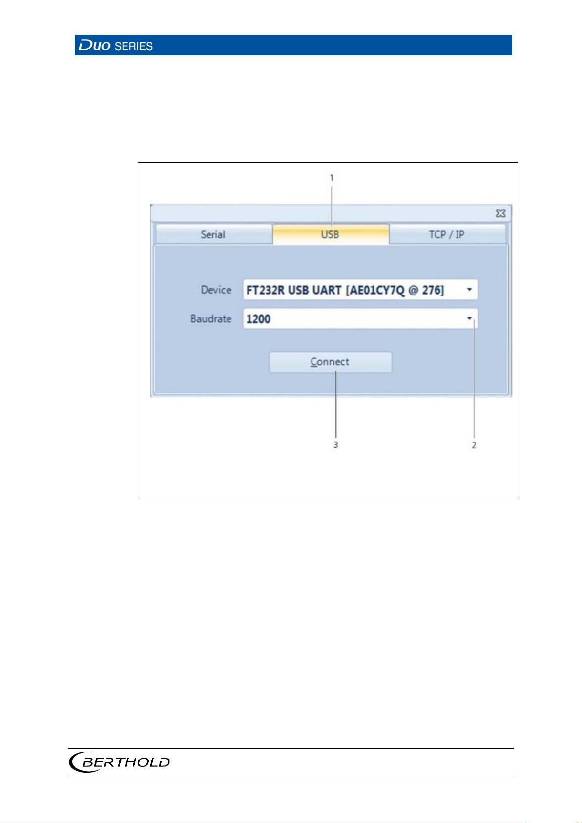
USB tab
Connect button
Fig.
u The program opens.
7. Click on the tab <USB> (Fig. 37, item 1).
8. Select a baud rate of 1200 in the selection menu (Fig. 37, item 2).
9. Click on <Connect> (Fig. 37, item 3).
2
Selection of baud rate
37 Connection Window "Flash Loader"
56926BA2, Rev. 02, 04/2019
Page 70
8 Maintenance and Repair
LB 4700
66
Fig.
1
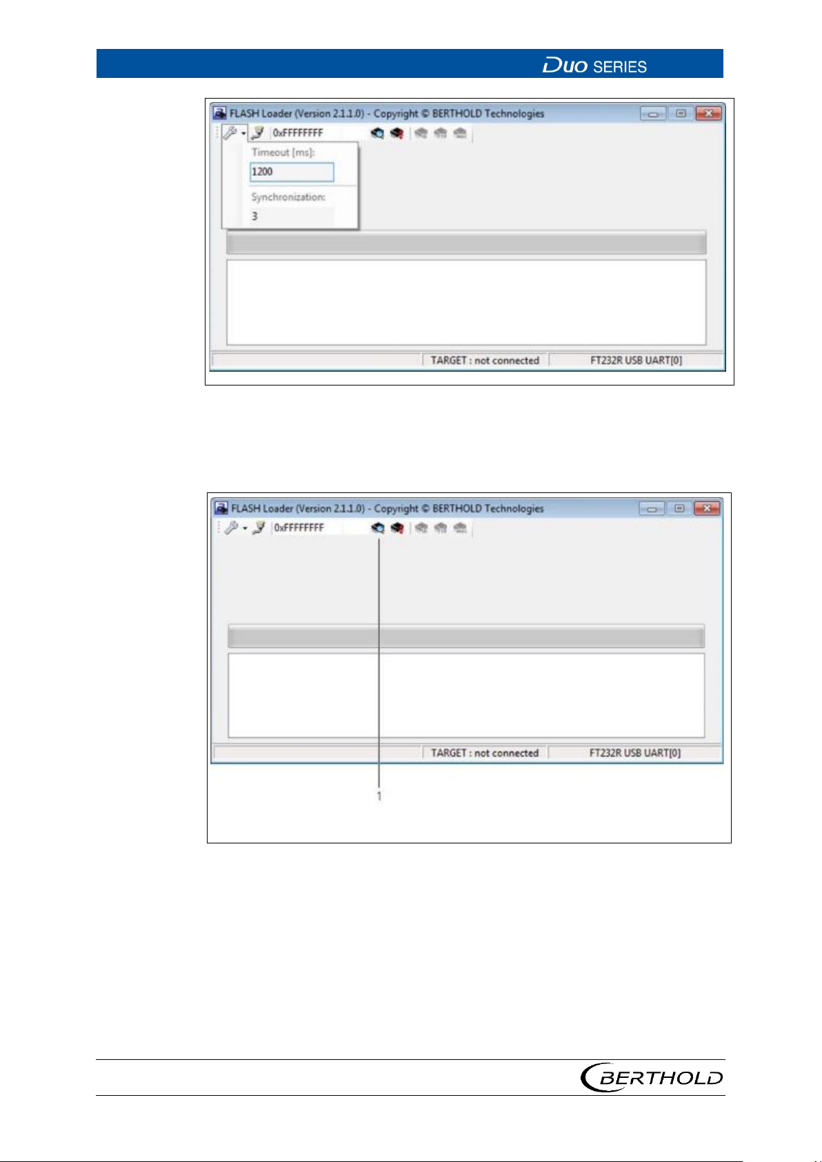
Button <detect device>
Fig.
38 Flash Loader Main Screen
10. In the menu "Settings", set the value "Timeout" to 1200 and the value "Syn-
chronisation" to 3.
56926BA2, Rev. 02, 04/2019
39 Flash Loader Main Screen
11. Click on the button <detect device> (Fig. 39, item1).
o The program establishes a connection to the detector.
Page 71
LB 4700
8 Maintenance and Repair
67
1
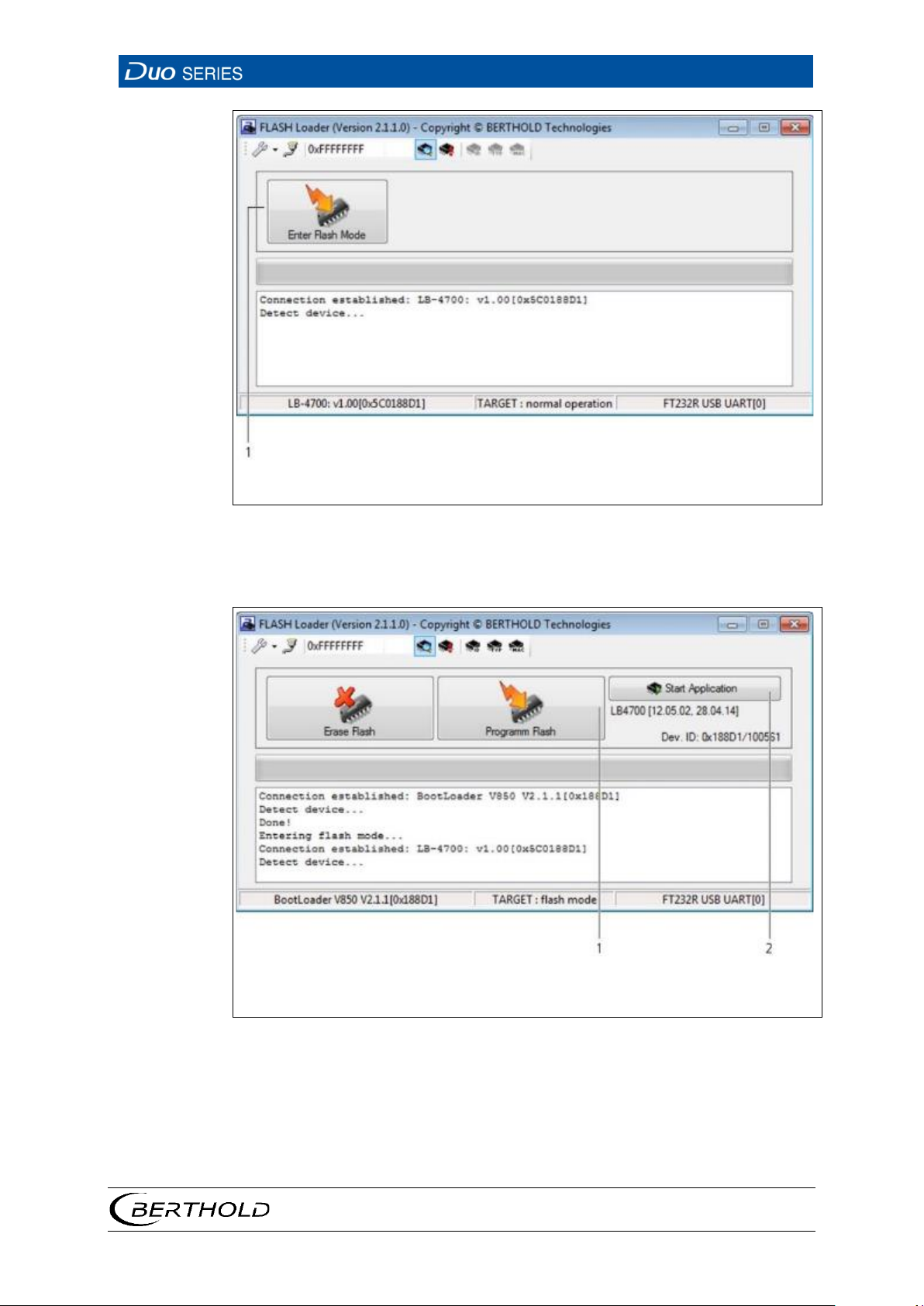
Button <Enter Flash Mode>
Fig.
1
Button <Program Flash>
2
Button <Start Application>
Fig.
40 Flash Loader Connection
12. Click on the button <Enter Flash Mode> (Fig. 40, item 1).
41 Flash Loader “Program Flash” Page
13. Click on the button <Program Flash> (Fig. 41, item 1).
A dialogue window is opened.
14. Select the corresponding file for the software update
The detector is programmed with the respective software.
56926BA2, Rev. 02, 04/2019
Page 72
8 Maintenance and Repair
LB 4700
68
NOTICE
NOTICE
Make sure that the detector is only programmed with compatible software.
15. Click on the button <Start Application> (Fig. 40Fig. 41, item 2) after the pro-
gramming has ended.
Reset the detector to the factory default settings if the first or second digit of
the software version has changed. Make a note of the settings before the factory reset and enter them again after the reset is completed.
56926BA2, Rev. 02, 04/2019
Page 73
LB 4700
8 Maintenance and Repair
69
DANGER
Danger to life from electric shock!
-
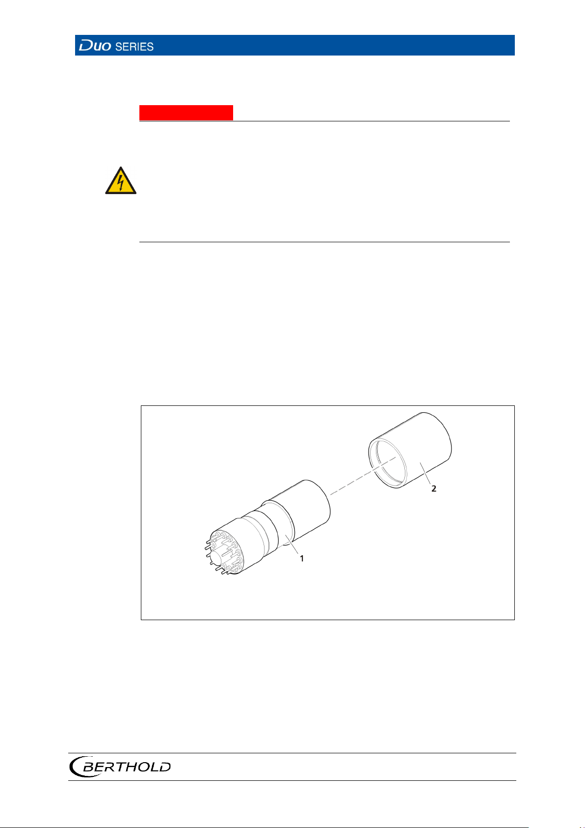
1 2 Photomultiplier (PMT)
Scintillator
Fig.
8.3 Visual Inspection of Scintillator and Photomultiplier
j
u The installation may only be carried out by a qualified electrician.
u Please adhere to the relevant safety regulations.
u Installation/maintenance may only be carried out if the device has been de
energised.
u Only open the device when free of voltage.
In case of an electric shock, carry out first aid measures and immediately call an
emergency service.
Errors on the scintillator and/or photomultiplier manifest themselves by a too small
or too steep plateau (see chapter 6.4.5). Such errors can often already be recognized in a visual inspection. To do so, the scintillator and the photomultiplier must
be disassembled.
The scintillator has to be crystal clear on the inside and neither have any cracks nor
dull spots. A clear yellow to brown discolouration indicates a thermal overload and
requires replacing the scintillator.
The window of the photomultiplier has a deposited film as a photocathode. This
layer causes the window to have a slightly brownish or smoked glass colour. If this
layer is no longer present or is stained, the cathode is damaged (e.g. through overheating, broken glass or light). In this case, the multiplier has to be replaced.
42 Representation of the Scintillator and the Photomultiplier
56926BA2, Rev. 02, 04/2019
Page 74
8 Maintenance and Repair
LB 4700
70
NOTICE
8.4 Replacing the Entire Detector
To replace the detector, proceed as follows:
1. Document all software parameters of the installed detector
2. Take the old detector out of operation as described in chapter “Decommis-
sioning”.
3. Install the new detector as described in chapter “Installation”.
4. Perform the electrical installation as described in chapter “Electric Installa-
tion”.
5. Transfer the software parameters of the old detector to the new one.
If the detector has been previously used, please note that detectors that were
used in non-hazardous areas must no longer be used in a hazardous area!
Intrinsically safe detectors whose intrinsically safe signals were connected to
non-intrinsically safe circuits must not be connected to intrinsically safe circuits.
56926BA2, Rev. 02, 04/2019
Page 75
LB 4700
8 Maintenance and Repair
71
DANGER
Danger to life from electric shock!
-
WARNING
Danger to life by explosion!
If the detector is located in a potentially explosive atmosphere, it is essential
to observe the corresponding instructions and safety instructions in the
NOTICE
8.5 Replacing the Electronics Module
j
u The installation may only be carried out by a qualified electrician.
u Please adhere to the relevant safety regulations.
u Installation/maintenance may only be carried out if the device has been de
energised.
u Only open the device when free of voltage.
In case of an electric shock, carry out first aid measures and immediately call an
emergency service.
j
u
safety manual / explosion protection manual.
The removal and installation of parts of the DuoSeries detector must be performed in clean workshop environment.
56926BA2, Rev. 02, 04/2019
Page 76
8 Maintenance and Repair
LB 4700
72
1
2
3
4
5
6
7
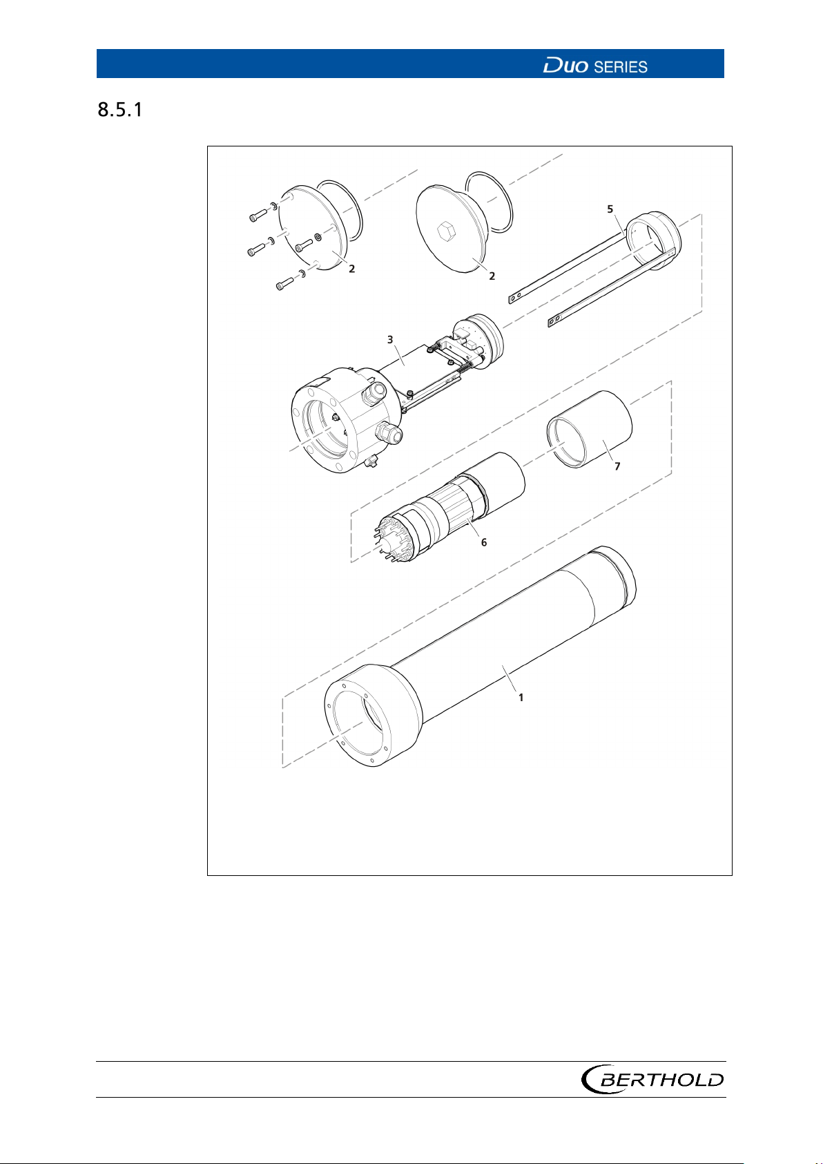
Stainless steel housing (housing tube)
Scintillator
Fig.
Disassembling the Electronics Module
1. Document all software parameters of the installed detector
2. Disconnect the detector from the power supply and de-energise it and any
3. Loosen the four screws of the housing cover and remove the cover (Fig. 43,
4. Loosen the six screws that hold the detector housing to the socket.
56926BA2, Rev. 02, 04/2019
Cover with fixing screws
Sealing
Base unit with detector electronics
Photomultiplier holder
Photomultiplier
43 Removing Detector Electronics
potentially connected peripherals.
item 2).
Page 77

LB 4700
8 Maintenance and Repair
73
5. Carefully pull out the electronics module and the scintillator/multiplier combi-
nation on the socket.
6. Remove the holder (Fig. 43, item7) with the scintillator/multiplier combination
of the electronics by loosening the four Phillips screws on the side of the
holder.
7. Pull the scintillator/multiplier combination out of the connection socket.
8. Now, the complete electronics module can be replaced.
Installing the Electronics Module
To assemble the electronics module, proceed in reverse order.
1. Replace the O-ring which seals the housing.
2. Make sure that no humidity or metal chippings are inside the connection com-
partment.
3. Carefully insert the electronics module on the socket with the scintillator/mul-
tiplier combination forward back into the housing.
4. Fasten the socket again on the detector housing. Tighten the screws alternat-
ing and equally on both sides.
5. Check and replace, if necessary, the O-ring that seals the connection compart-
ment.
6. Carefully close the connection compartment with the lid. To do this, fit the
housing cover onto the housing and tighten the Allen bolts with the specified
torque: depending on the model M5 with 4 Nm (standard values).
If you have installed a new electronics module:
• Remove the adhesive label with the Dev. ID and attach the supplied new
adhesive label.
• Reconnect the supply voltage to the detector.
• Now set the software parameters based on the list that you noted at the
beginning.
56926BA2, Rev. 02, 04/2019
Page 78
8 Maintenance and Repair
LB 4700
74
DANGER
Danger to life from electric shock!
-
WARNING
Danger to life by explosion!
If the detector is located in a potentially explosive atmosphere, it is essential
to observe the corresponding instructions and safety instructions in the
8.6 Replacing the Scintillator
j
u The installation may only be carried out by a qualified electrician.
u Please adhere to the relevant safety regulations.
u Installation/maintenance may only be carried out if the device has been de
energised.
u Only open the device when free of voltage.
In case of an electric shock, carry out first aid measures and immediately call an
emergency service.
u
safety manual (chapter 2).
Disassembling the Scintillator
The multiplier should not be subject to bright light during the following working
steps.
1. Remove the electronics module through the action steps 1 - 7 as described in
the chapter 8.5.1.
2. Point detectors: Carefully screw off the scintillator from the photomultiplier.
Rod detectors: Remove the scintillator carefully from photomultiplier.
3. Clean the optical contact surfaces with a soft cloth from silicon oil residues.
Installing the Scintillator
1. Before assembly, apply a drop pure silicon oil (BERTHOLD ID no. 18844) be-
tween the scintillator and the multiplier and slightly distribute it by rubbing
to ensure a good optical connection between the two components.
2. Reassemble the scintillator and the multiplier and install the holder by retight-
ening the 4 Phillips screws.
56926BA2, Rev. 02, 04/2019
Page 79
LB 4700
8 Maintenance and Repair
75
DANGER
Danger to life from electric shock!
-
WARNING
Danger to life by explosion!
If the detector is located in a potentially explosive atmosphere, it is essential
corresponding instructions and safety instructions in the
8.7 Replacing the Scintillator/Multiplier Combination
j
u The installation may only be carried out by a qualified electrician.
u Please adhere to the relevant safety regulations.
u Installation/maintenance may only be carried out if the device has been de
energised.
u Only open the device when free of voltage.
In case of an electric shock, carry out first aid measures and immediately call an
emergency service.
u
to observe the
safety manual.
1. Remove the electronics module through the action steps 1 - 7 as described in
the chapter 8.5.1.
2. Insert the new crystal/multiplier combination in the socket. Please observe the
coding lug.
3. Insert the electronics module again, see chapter 8.5.1.
4. Check the measuring function. Should there be discrepancies, perform a new
calibration (see operating instructions of the associated evaluator device).
56926BA2, Rev. 02, 04/2019
Page 80

8 Maintenance and Repair
LB 4700
76
56926BA2, Rev. 02, 04/2019
Page 81

LB 4700
9 Accessories
77
Part number
Accessory part
IMPORTANT
9 Accessories
Available accessories
61087 Water cooling system for point detectors
61231 Water cooling system for rod detector 500 mm
61235 Water cooling system for rod detector 1000 mm
61238 Water cooling system for rod detector 1500 mm
61241 Water cooling system for rod detector 2000 mm
11814 Collimator with frontal irradiation
04506 Collimator with side irradiation
61624 Cable gland set for extended temperature range
31346 Set of mounting clamps for detectors without water cool-
ing system
31347 Set of mounting clamps for detectors with water cooling
system
39246 Holder for point detectors without water cooling system
39247 Holder for point detectors with water cooling system
32024 Signal cable
46413 Signal cable for intrinsically safe detectors
Available spare parts are listed in the document technical information.
56926BA2, Rev. 02, 04/2019
Page 82

9 Accessories
LB 4700
78
IMPORTANT
BERTHOLD TECHNOLOGIES GmbH & Co. KG
If you have any questions regarding accessories or spare parts, please contact
the service department of
Calmbacher Str.22, 75323 Bad Wildbad, www.berthold.com, Tel.: +49 7081177-0, Fax: +49 7081-177-100, [email protected].
,
56926BA2, Rev. 02, 04/2019
Page 83
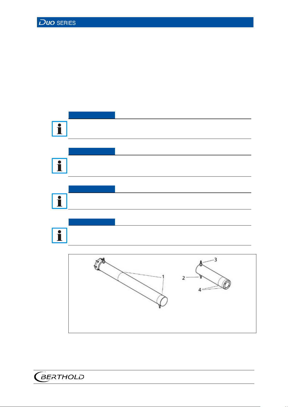
LB 4700
9 Accessories
79
NOTICE
NOTICE
NOTICE
NOTICE
1
4
Marking grooves on the water cooling system of the rod detector
Marking grooves on the water cooling system of the point detector
Fig.
9.1 Water Cooling System
To protect the scintillators against overly high temperatures, a water cooling system is optionally available. A water cooling system must be used if the detector
temperature may exceed +60 °C.
In this respect, ambient temperature, sun light, radiant heat of hot components
and the transition of heat from installation fixtures should be considered. With
water cooling, the detectors can be operated at a maximum ambient temperature
of 100 °C.
For the minimum cooling water requirement, please refer to the document technical information.
When operating in areas with danger of explosion, observe the specific ambient
temperature limits, which are specified in the safety manual and in the document technical information.
If water remains in the water cooling systems at ambient temperatures below
the frost point, the cooling water system can be damaged.
u If there is a risk of frost, empty the water cooling system.
If there is a risk that the maximum operating temperature is exceeded, the cooling water circuit must remain in operation even if the detector is switched off.
A failure of the cooling water system or an insufficient flow can overheat the
detector and thereby cause damage. For cooling, exclusively use water of drinking water quality.
2
Water supply
3
Water discharge
44 Water Cooling System Point Detector/Rod Detector
56926BA2, Rev. 02, 04/2019
Page 84
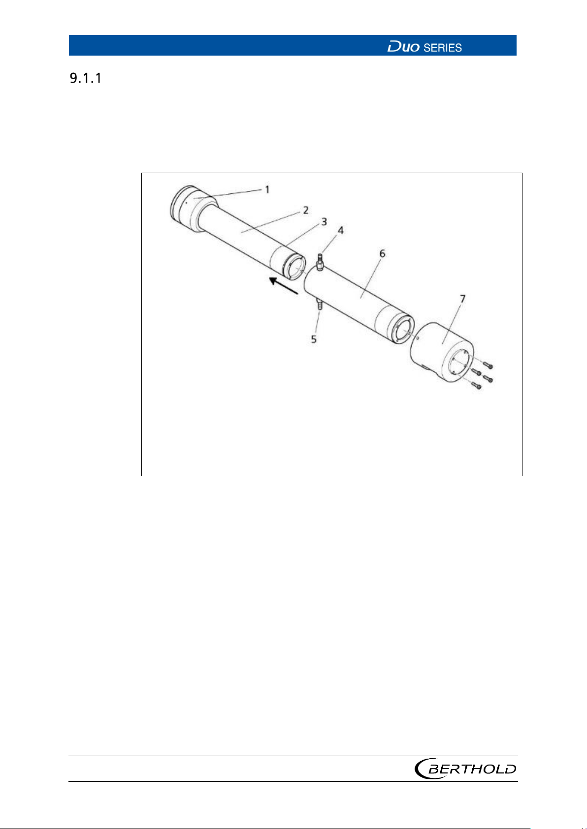
9 Accessories
LB 4700
80
1
7
Connection compartment
Collimator
Fig.
Installation and Connection of the Water Cooling Sys-
tem
If the detector is equipped with a water cooling system, the cooling water nozzles
must be aligned so that the water supply lines can be connected freely. Make sure
that the water lines do not run in front of the radiation window. So that no air
pockets form in the cooling water, the detectors must be mounted as follows:
2
Point detector
3
Marking groove
4
Water discharge
5
Water supply
6
Water cooling system
45 Point Detector with Water Cooling System
1. Slide the water cooling system (Fig. 45, item 6) with the connection nozzles
pointing forward towards the connection compartment.
2. Attach the water cooling system with the provided screws at the pipe of the
detector.
If the detector is mounted horizontally, the bottom connector (Fig. 45, item 5) must
be used as a water supply.
If the detector is mounted vertically, the connection compartment must be oriented upward, so that the connections are located at the upper end of the water
cooling system.
56926BA2, Rev. 02, 04/2019
Page 85
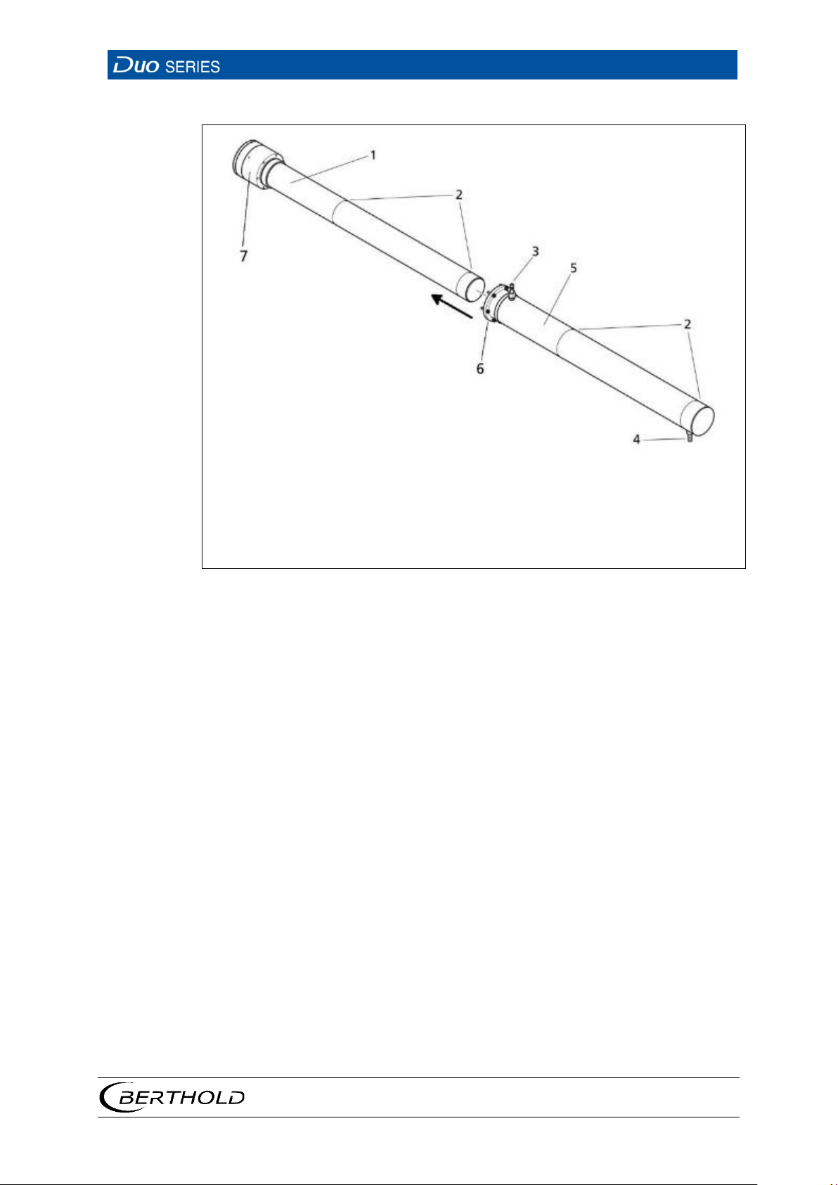
LB 4700
9 Accessories
81
1
7
Rod detector
Connection chamber
Fig.
2
Marker grooves
3
Water discharge
4
Water supply
5
Water cooling system
6
Connection flange
46 Rod Detector with Water Cooling System
1. Slide the water cooling system (Fig. 46, item 5) with the connecting flange (Fig.
46, item 6) in the direction of the connection chamber
2. Fasten the water cooling system on the detector socket with the enclosed
screws.
Depending on the detector assembly, (horizontally or vertically, connection compartment on top or at the bottom) the respective lower cooling water connection
should be used as a feed, so that no air pockets form in the cooling water.
56926BA2, Rev. 02, 04/2019
Page 86

9 Accessories
LB 4700
82
NOTICE
9.2 Conversion Kit for Extended Temperature Range
If DuoSeries detectors are operated in the extended temperature range of -40°C to
+ 100°C (with additional water cooling), a conversion kit is required per detector.
The conversion kit includes metal cable glands, which are certified for operation in
the extended temperature range.
When operating in areas with danger of explosion, observe the specific ambient
temperature limits, which are specified in the safety manual / explosion protection manual, and in the technical information.
56926BA2, Rev. 02, 04/2019
Page 87
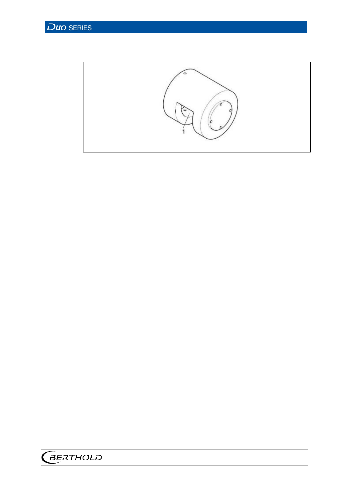
LB 4700
9 Accessories
83
1
Radiation window
Fig.
9.3 Collimator
47 Collimator
The optional lead collimator for the point detector protects against interfering
background radiation and ensures higher reliability and accuracy. The collimator is
available with a radial (irradiation from the side) or axial (irradiation from the
front) radiation window.
56926BA2, Rev. 02, 04/2019
Page 88
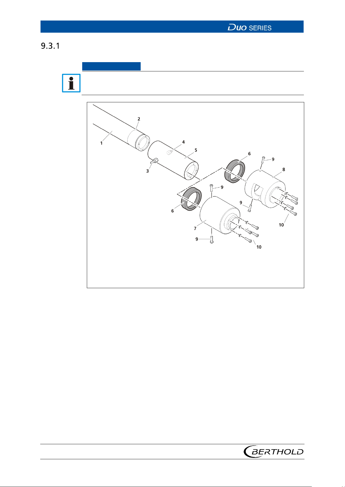
9 Accessories
LB 4700
84
NOTICE
1
6
Detector
Spacer ring
7
Collimator with frontal irradiation
Fig.
Collimator Assembly with Water Cooling System
For collimators with frontal irradiation and perpendicular detector mounting,
the collimator must be aligned upwards. If the collimator is aligned downwards,
there is a risk of incorrect readings due accumulation of water.
2
Marking groove
3
Water discharge
4
Water supply
5
Cooling jacket
48 Assembly Collimator with Water Cooling
1. Remove the spacer ring from the collimator by unscrewing the screws on the
side.
2. For fixing collimator with water cooling must be used longer screws.
3 mm -> 5 mm.
3. Slide the collimator over the water cooling system so that the radiation win-
dow is positioned in the direction of the source. To do so, position the collimator and the cooling water system so that the pattern of their fastening
holes matches the one of the detector. Make sure that the position of the
connection nozzles does not obstruct later installation of the water supply.
8
Collimator with side irradiation
9
lateral screws
10
frontal screws
56926BA2, Rev. 02, 04/2019
Page 89
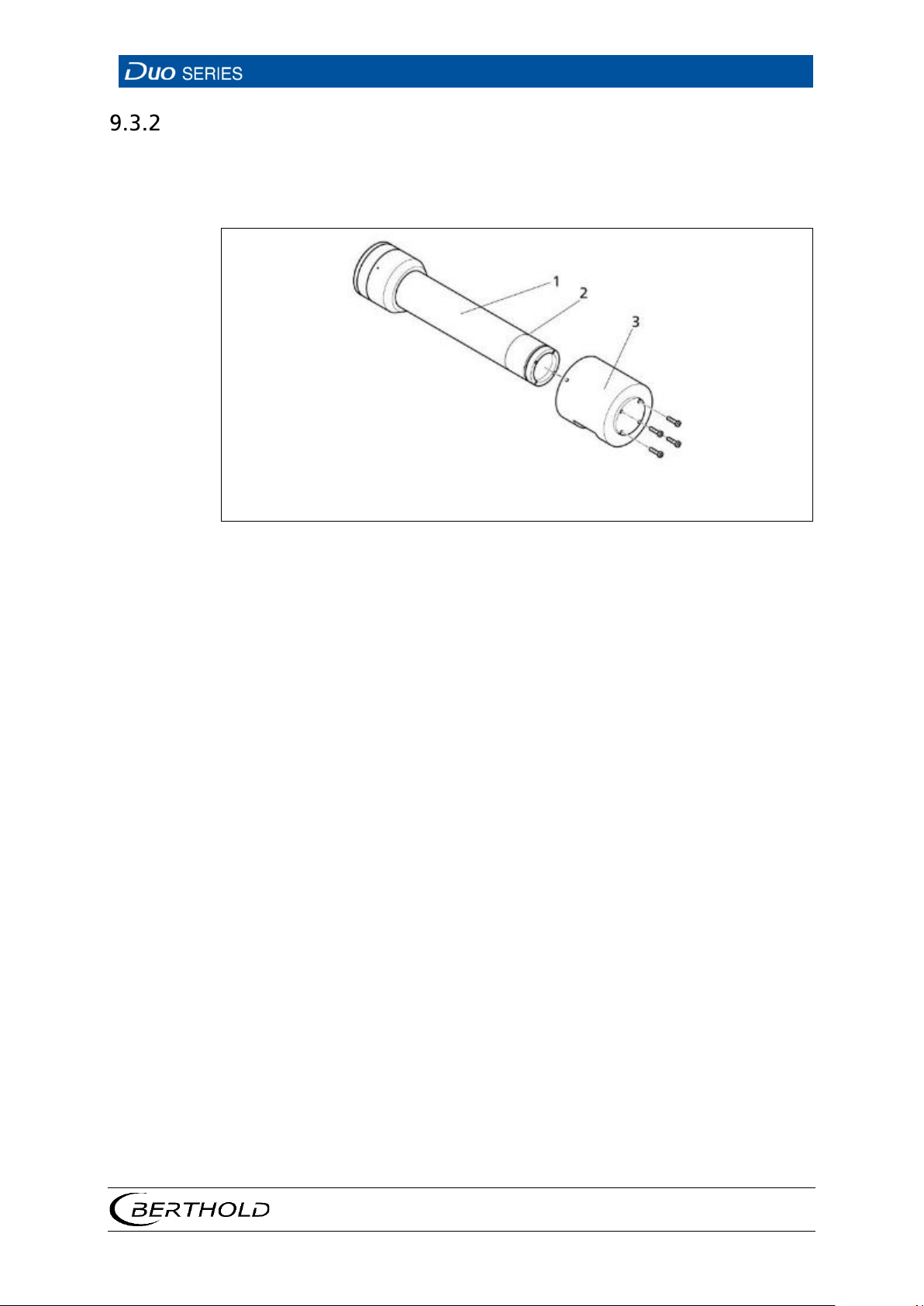
LB 4700
9 Accessories
85
1
3
Detector
Collimator
Fig.
Collimator Assembly without Water Cooling System
Slide the collimator over the detector housing so that the radiation window is positioned in the direction of the source. To do so, position the collimator so that the
pattern of its fastening holes matches the one of the detector.
2
Marking groove
49 Assembly Collimator without Water Cooling
56926BA2, Rev. 02, 04/2019
Page 90

9 Accessories
LB 4700
86
56926BA2, Rev. 02, 04/2019
Page 91
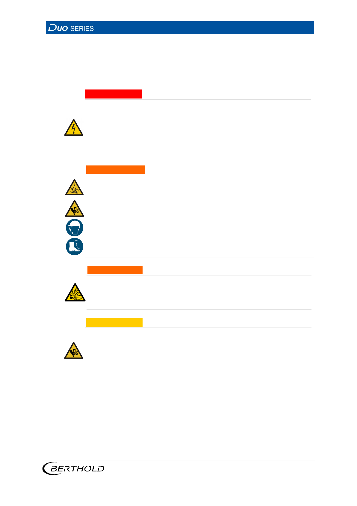
LB 4700
10 Decommissioning
87
DANGER
Danger to life from electric shock!
WARNING
Danger of injury by falling loads
Only use tested sling gear components appropriate for the transport weight.
Observe the marking for the centre of gravity on the outer packaging, if ap-
WARNING
Danger to life by explosion
If the detector is located in a potentially explosive atmosphere, it is essential
to observe the corresponding instructions and safety instructions in the
CAUTION
Danger of injury caused by heavy and bulky system components
Heavy and bulky system components should only be handled using aids and
10 Decommissioning
j
u The decomissioning may only be carried out by a qualified electrician.
u Please adhere to the relevant safety regulations.
u Only open the device when free of voltage.
In case of an electric shock, carry out first aid measures and immediately call an
emergency service.
u Never stand underneath a lifted or suspended load, keep at a safe distance.
u
u
plicable.
u Wear head protection and safety shoes.
u
safety manual / explosion protection manual.
u
by at least 2 persons.
u Observe the guidelines for safe handling of heavy loads.
u Ensure stability and use the provided fixing possibilities.
Follow this sequence for decommissioning:
1. Remove all cables from the detector.
2. Remove the detector with/without water cooling system out of its holder.
3. Remove the detector from the water cooling system if necessary.
56926BA2, Rev. 02, 04/2019
Page 92

10 Decommissioning
LB 4700
88
CAUTION
Toxic!
The device is to be disposed of according to applicable legal regulations by
10.1 Disposal
The product contains electronic components containing toxic substances that
are harmful to health.
u
a specialised waste management company.
If the product has been used, you can dispose of it through a waste management
company in accordance with the statutory provisions.
56926BA2, Rev. 02, 04/2019
Page 93

BERTHOLD TECHNOLOGIES GmbH & Co. KG
Modifications due to technical advancement reserved.
© BERTHOLD TECHNOLOGIES GmbH & Co. KG Language: English Printed in Germany
04/2019 Rev.-No.: 02, 04/2019
Calmbacher Str. 22
75323 Bad Wildbad
Germany
www.berthold.com Id.-No. 56926BA2
Page 94
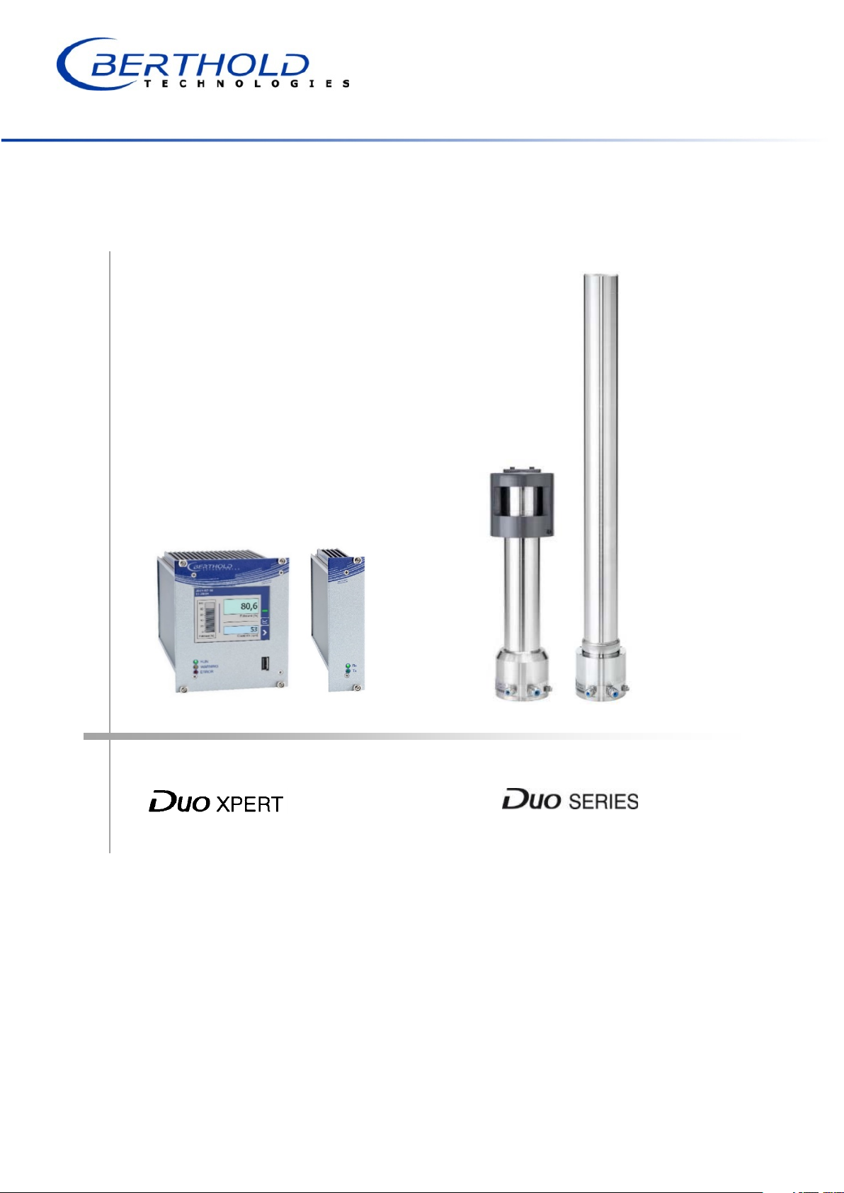
Unité d'évaluation Détecteurs
LB 47x LB 4700
Informations sur la sécurité
56925BA59
Rev. No.: 02, 01/2019
Page 95

Page 96

BERTHOLD TECHNOLOGIES GmbH & Co. KG
Calmbacher Str. 22
75323 Bad Wildbad, Germany
www.Berthold.com
Telephone +49 7081 177-0
Fax +49 7081 177-100
Page 97
1
A propos de ce manuel d’utilisation
1
Signalement
Source et conséquence
DANGER
AVERTISSEMENT
PRUDENCE
1 A propos de ce manuel
d’utilisation
1.8 Avertissement
Les avertissements sont identifiés comme suit :
Explication si requise
Prévention
En cas de danger
•
Symboles d’alerte : (triangle d’alerte) attire l’attention sur le risque.
Signalement : Indique la sévérité du danger.
•
Source : Précise le type ou la source de danger.
•
Conséquence : Décrit les conséquences d’un non respect.
•
Prévention : Précise comment le risque peut être écarté.
•
En cas de danger : Précise quelles actions sont requises en cas
•
d’occurrence du risque
1.8.1 Symboles employés dans le manuel d’utilisation
Dans ce manuel, les avertissements indiqués avant les instructions d’utilisation se
réfèrent aux risques de blessures ou de dégâts matériels. Les mesures de prévention
de danger décrites doivent être respectées.
Indique un danger majeur imminent, qui entraînera certainement des
blessures sérieuses ou la mort s’il n’est pas évité.
Indique un danger potentiel qui peut entraîner des blessures sérieuses ou la
mort s’il n’est pas évité.
Se réfère à une situation potentiellement dangereuse qui peut entraîner des
blessures physiques mineures ou graves, ou des dégâts matériels si elle n’est
pas évitée.
56925BA59 Rev. 02, 01/2019
Page 98
A propos de ce manuel d’utilisation
2
RECOMMANDATION
IMPORTANT
Si cette information n’est pas appliquée, un dysfonctionnement et/ou un
dégât matériel peuvent apparaître.
Les sections identifiées avec ce symbole signalent des informations
importantes du produit ou de son fonctionnement.
Tip
Fournit des conseils sur l’application ou d’autres informations utiles.
1
56925BA59 Rev. 02, 01/2019
Page 99
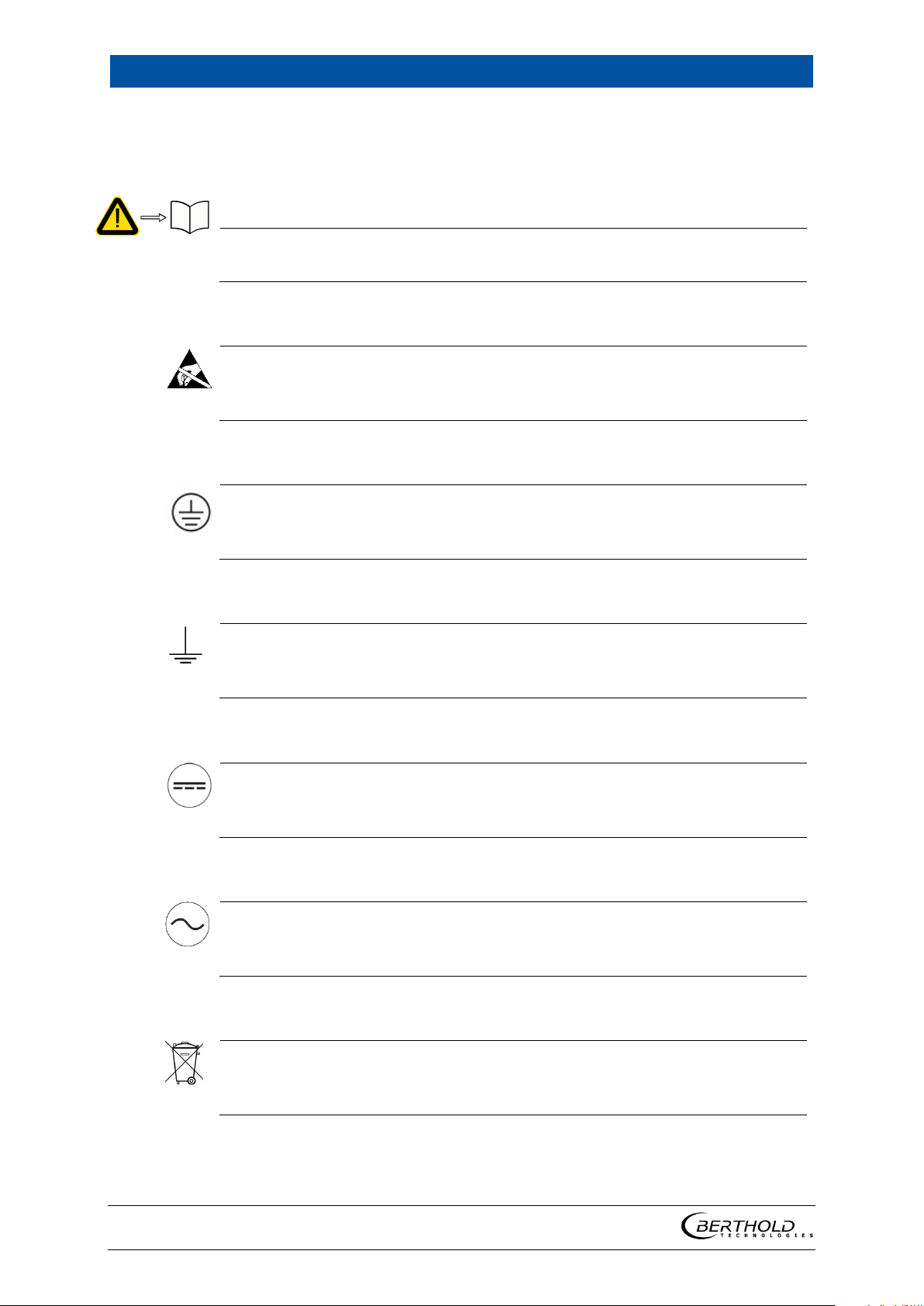
1
A propos de ce manuel d’utilisation
3
Lire le manuel d’utilisation
Décharge électrostatique
instructions de manipulation. Composants sensibles aux
décharges électrostatiques. Veuillez suivre les instructions de ce manuel
Connexion de mise à la terre
Raccordement equipotentiel
Tension continue
Tension alternative
Déchet non domestique
1.8.2 Symboles utilisés sur l’appareil
Veuillez suivre les instructions dans ce manuel d’utilisation.
Veuillez noter les
d’utilisation.
Raccorder le conducteur de mise à la terre à cet endroit.
Raccorder le conducteur d’équipotentialité à cet endroit
L’appareil fonctionne en tension continue et ne doit être raccordé qu’à une
source de tension continue.
L’appareil fonctionne en tension alternative et ne doit être raccordé qu’à une
source de tension alternative.
Cet appareil électrique ne doit pas être éliminé avec les déchets domestiques
56925BA59 Rev. 02, 01/2019
Page 100

A propos de ce manuel d’utilisation
4
1.9 Conformité
La société BERTHOLD déclare par la présente, sous son entière responsabilité, que
la conception de ce produit mis sur le marché par BERTHOLD est conforme aux
directives EU indiquées dans la déclaration de conformité originale.
Cette disposition devient nulle en cas de modifications non autorisées par Berthold
ou dans le cas d’une utilisation impropre.
Pour la déclaration de conformité originale, se «Technical information».
1
56925BA59 Rev. 02, 01/2019
 Loading...