

Page 1
Contactless Measurement
of Level
LB 440
PROCESS CONTROL
Page 2
Level Gauge LB 440
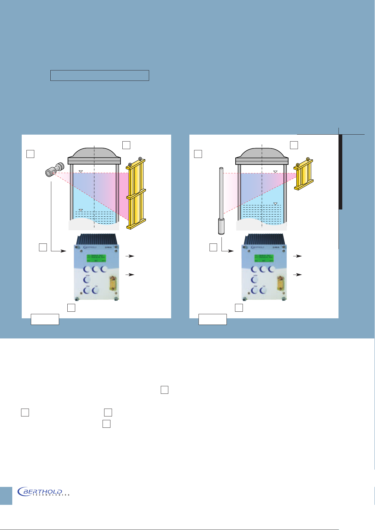
The measuring system LB 440 is used
for the contactless, continuous
measurement of liquids and bulk
materials in reactors, vessels and
bunkers. The measurement is not
1 Rod Source
2 Point
Detector
Max
Min
with Shielding
affected by the chemical and physical
properties of the product being
measured. The level measurement is
adapted to the specific geometry of
the vessel.
1 Point Source
2 Rod
Detector
Max
Min
with Shielding
3
0/4 ... 20 mA
Alarm
4 Evaluation Unit LB 440
Figure 1 Figure 2
Measuring Arrangement
Figures 1 and 2 show schematic layouts of typical measuring arrangements. It is comprised of the source 1
mounted on the outside of the container, a detector
2 and the connection cable 3 from the detector
to the evaluation unit LB 440 4 . Source and detector
3
0/4 ... 20 mA
Alarm
4 Evaluation Unit LB 440
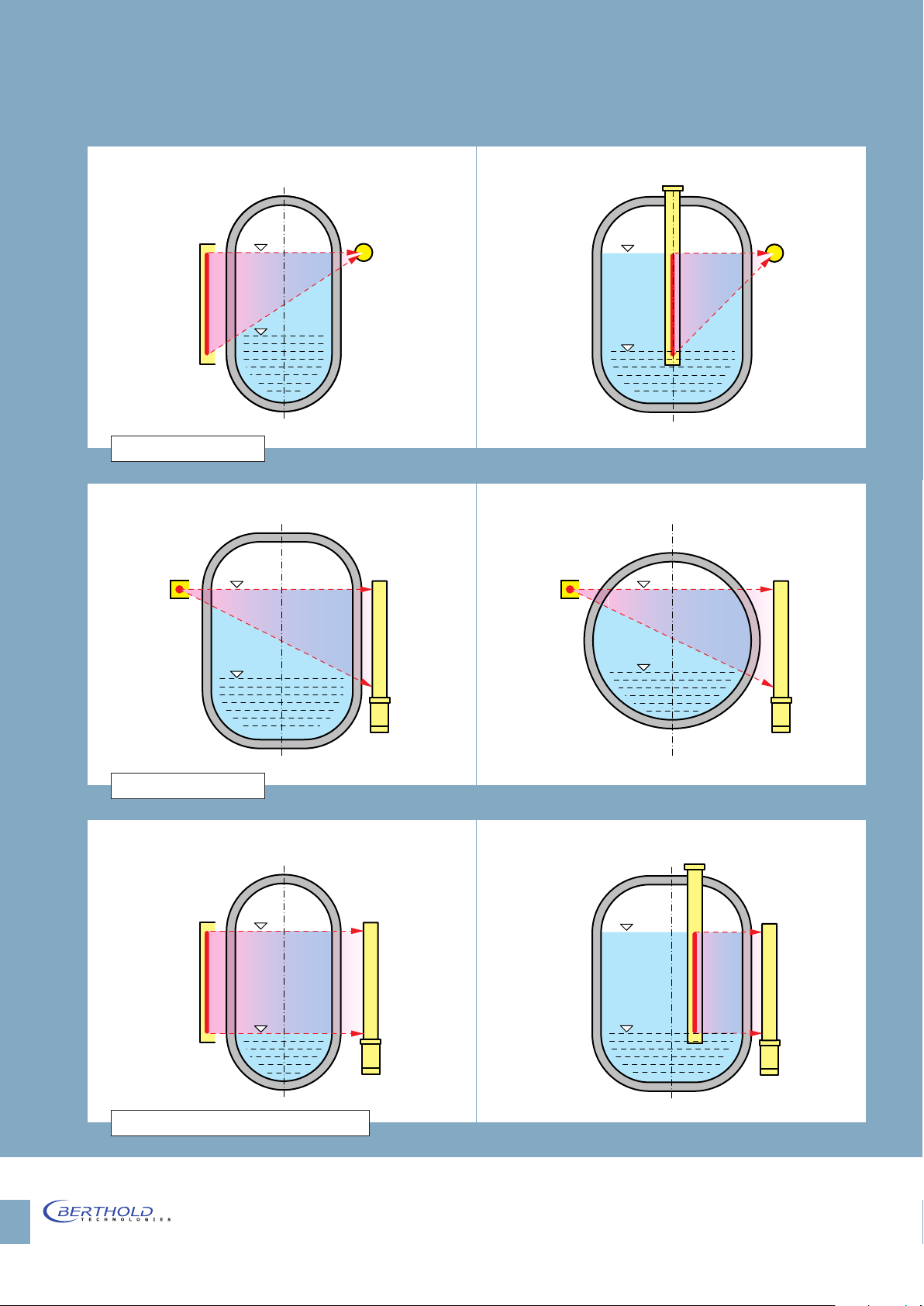
applications a rod source and rod detector (Fig. 5) can
be used. Which of these options is selected is dependent
upon the measuring geometry, the measuring task,
ambient factors or even considerations of space and
money. For larger measurement ranges several rod
form a radiation field corresponding to the size of the
measuring range. This can be achieved by using a rodshaped source and a point detector (Fig. 3) or a pointshaped source and a rod detector (Fig. 4), for special
detectors can be used together in a line. Signals from
individual detectors are transmitted via slave units to a
master evaluation unit for indication of product level.
Page 3
General Arrangements
Rod Source
Figure 3: Rod Source
Point Source
Detector
Rod Detector
Point Source
Detector
Rod
Source
Rod Detector
Figure 4: Rod Detector
Rod Source
Figure 5: Rod Source with Rod Detector
Rod Detector
Rod
Source
Rod Detector
3
Page 4
Evaluation Unit LB 440
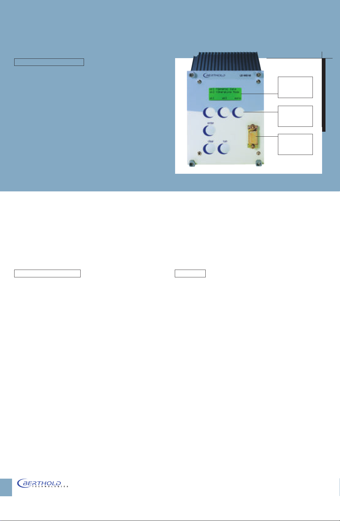
The evaluation unit incorporates state of the art
microprocessor technique with 32-bit processor for
high computing performance and high accuracy
4-line,
illuminated
LCDdisplay
together with most simple operation. The software is
tailored to the measuring principle. More than 40 years
of experience in the field of radiometric measurement
technique are consequently utilized.
In addition, the evaluation unit features:
■ Compact design in 19“-module (3HE; 21 TE) for
installation in a wall housing or 19“racks.
■ Illuminated 4-line LCD-display.
■ Operation via 6 membrane keys.
■ Convenient multilingual and user-guided
dialog via “softkeys”.
■ Continuous self-monitoring of the electronics.
■ Data protection without battery backup by
saving all calibration data to a FLASH-Memory.
Source with Shielding
All radioactive sources used for industrial applications
„Softkeys“ for
menu-guided
operation
Interface
RS 232
excessive radiation levels. For rod sources as well as for
point sources, the shielding is installed vertically on a
bracket. The radiation channel is specially designed for
this measuring arrangement. This ensures a simple and
non-critical installation.
Detectors
Typically, scintillation counters are used as radiation
are encapsulated in stainless steel, so that radioactive
substance is kept separate and isolated from the
material beeing measured. Depending on the measuring task, one can either work with 60Co or
137
Cs
sources. The radioactive material of the 60Co rod source
is a metal wire wound around a mandrel of the required
length. By winding at a variable pitch, any linearization
can be achieved, even for complicated measuring
geometries. Depending on the measuring task, either
60
Co or
137
Cs are selected as point sources. The sources
are built into sturdy shieldings which include a lockable
radiation exit slit that is directed toward the detector.
The shielding is adapted to the required activity so
that operating personnel are never exposed to any
detectors for continuous level measurements. These
detectors consist of a NaI crystal; the scintillator of rod
detectors are made of plastic. Flashes of light are
created in the detector by the radiation. The number
of flashes is proportional to the intensity of the
radiation field. The crystal is optically coupled to a
photomultiplier which, together with the electronics,
converts the flashes of light into electrical pulses.
The special benefits of scintillation counters are their
high sensitivity to Gamma radiation, low source
activity and unlimited useful life. The signals are
transfered to the evaluation unit via two-wire technique
with FSK-modulation to ensure a high level of
interference immunity.
4
Page 5
Contactless Measurement
Principles of Measurement
The Level Gauge LB 440 operates according to radiometric principle, utilizing the physical law that gamma
radiation is attenuated as it passes through matter.
Since the source type and the absorption path are
constant in this case, the measurement is affected only
by the presence of the medium. All other physical
properties such as pressure, temperature, viscosity and
colour have no influence. Since the absorption law
follows an exponential curve, the measuring effect
with normal container dimensions becomes practically
independent of any density changes in the medium
being measured.
As a consequence, the radiometric measuring method
features a very high level of operational safety and
requires practically no maintenance, even under difficult operating and ambient conditions. The use of
scintillation counters as radiation detectors and careful
project engineering ensure that the lowest possible
source activities and the best shieldings will be used.
The radiation exposure of the operating staff will
clearly stay below the extremely low values permitted
by law, which are about as high as the natural environmental radiation. The use of radiometric measuring
systems has to comply with the applicable radiation
Project Engineering
When designing the level gauging system, the special
features of the production process and possible
contingent conditions should be taken into account,
in addition to the actual measuring task.
Relevant data along with dimensional drawings should
therefore be provided.
Engineering Data
■
Type and dimensions of the vessel
■
Wall thickness and wall material
■
Thickness and density of any
insulation
■
Size and position of the required
measuring range
■
Density and any special properties of
the medium in vessel
■
Gas density under operating condi-
tions in high pressure systems
■
Maximum speed of level variations
■
Ambient temperature at the
detector
■
Agitators or other internals, if any
protection regulations.
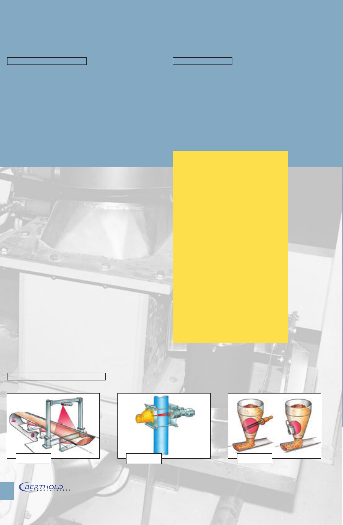
Other Applications from Berthold
Bulk Flow Density Moisture
5
Page 6

Technical Data LB 440
Evaluation Unit LB 440
Design 19" module 3 HE, 21 TE
protection class IP 20
Weight approx. 2 kg
Power supply 115/230 V AC +/–10 %
18 -32 V DC, 24 V AC
Power consumption approx. 30 VA (AC) 30 W (DC)
Operating temp. 0 ... +50° C (273 bis 323 K)
no condensation
Storage temp -40 ... +70° C (233 bis 343 K)
no condensation
Arrangements in a panel
in a 19" rack (max 4 Units)
wall mounted cabinet
Detector connection
Current output 4-20 mA, isolated
Digital inputs external start/stop
Digital output 1 relay for failure message, SPST
Interfaces RS 232 on front site / RS 485 rear
Multi lingual operation English, German, French
Berthold Technologies reserves the right to implement technical improvements and/or design changes without prior
notice.
[EEx ib] IIB
[EEx ib] IIC (Option)
impedance max. 500 Ohm
2 relays for threshold, SPST
max load: (non inductive)
AC: max. 250 V, max. 1 A, max. 200 VA
DC: max. 300 V, max. 1 A, max. 60 W
Probes
Housing Nema 4X and IP 65
Stainless Steel
Cable entrance M16 M12
Cable diameter 5 ... 10 mm 4 ... 7 mm
Connection cable LiYCY 2x 1 mm
Max. cable length with Berthold cable #32024
EEx ib IIB EEx ib IIC
1000 m 250 m
2
Explosion Proof
ATEX II 2G EEx de IIC T6
II 2G EEx ib d IIC T6
Dust (on request) II 2 D IP65 T 80° C
FM (option) Class I Division 1 Group A, B, C, D
Class II Division 1 Group E, F, G
Temp. Class T6 (85° C)
Point Probes NaI (TI) Scintillation counters
with automatic drift compensation
Temp. stability +/– 0,1 % (at –20 ... +50° C)
Operating temp. – 40 ... +60° C (233 ... 333 K)
Storage temp. – 40 ... +70° C (233 ... 343 K)
Water cooling option
Crystall size Dose rate Weight (kg)
(μSv/h)
for 300 cps
LB 4401-01 25/25 2,7 6
LB 4401-02 40/35 1,1 6
LB 4401-03 50/50 0,5 18
Rod Detectors Plastic scintillation counters
with automatic drift compensation
Temp. stability +/– 0,5 % (at –20 to +50° C)
Operating temp. – 40 ... +55° C (233 ... 328 K)
Storage temp. – 40 ... +55° C (233 ... 328 K)
Water cooling option
Typical dose rate at empty: 1μSv/h
Type Sensitive Dose rate Weight (kg) Weight (kg)
detector (μSv/h) without with water
length (mm) 1000 cps water cooling cooling
LB 4405-01 500 0,17 9 11,5
LB 4405-02 750 0,15 10,5 14
LB 4405-03 1000 0,09 12 17
LB 4405-04 1250 0,07 13,5 19,5
LB 4405-05 1500 0,06 15 22
LB 4405-06 2000 0,04 16,5 25
 Loading...