

Page 1
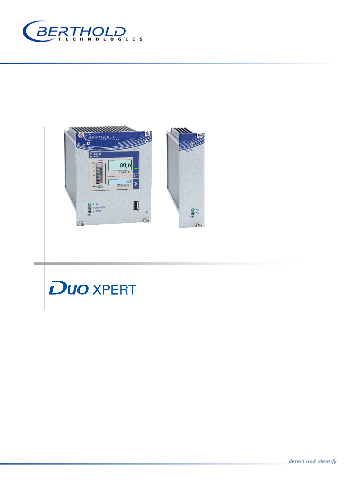
Evaluation unit
LB 470 Level
Operating Manual
56925BA2
Rev. No.: 03, 11/2017
Embedded software version as of vers. 1.3.0 (CPU) and 1.3.0 (MU)
Page 2

Page 3

BERTHOLD TECHNOLOGIES GmbH & Co. KG
Calmbacher Str. 22
75323 Bad Wildbad, Germany
www.berthold.com
Telephone +49 7081 177-0
Fax +49 7081 177-100
Page 4

Page 5

LB 470 Level Table of Contents
5
Table of Contents
1 About this Operating Manual ............................................................................ 7
1.1 16BSome Prior Remarks...................................................................................................... 7
1.2 17BStorage Place ................................................................................................................ 7
1.3 18BTarget Group ................................................................................................................ 7
1.4 19BValidity of the Operating Manual ............................................................................... 8
1.5 20BStructure of the Operating Manual ............................................................................ 8
1.6 21BCopyright ...................................................................................................................... 8
1.7 22BRepresentation ............................................................................................................. 8
1.8 23BWarning notes .............................................................................................................. 9
1.8.1 72BSymbols Used in the Operating Manual ..................................................................... 9
1.8.2 73BSymbols Used on the Device ...................................................................................... 11
1.9 Conformity .................................................................................................................. 12
2 Safety ................................................................................................................ 13
2.1 Dangers and safety measures .................................................................................... 13
2.2 Proper Use ................................................................................................................... 13
2.3 Qualification of the Personnel .................................................................................. 14
2.4 Operator's Obligations ............................................................................................... 16
3 System Description ........................................................................................... 17
3.1 Overview ..................................................................................................................... 17
3.2 Measuring Principle .................................................................................................... 18
3.3 System Components ................................................................................................... 19
3.3.1 74BSoftware ...................................................................................................................... 20
3.3.2 75BFront/rear view master EVU ....................................................................................... 21
3.3.3 76BFront/rear view slave module .................................................................................... 24
3.3.4 77BType plate ................................................................................................................... 24
3.4 Measurement arrangements ..................................................................................... 25
3.5 Storage ........................................................................................................................ 25
4 Installation ........................................................................................................ 29
4.1 General Instructions ................................................................................................... 29
4.2 Unpacking/Scope of Delivery ..................................................................................... 29
4.3 Installation variants .................................................................................................... 30
4.3.1 78BInstallation in the wall housing ................................................................................. 32
4.3.2 79BInstallation in the 19" subrack .................................................................................. 35
5 Electric Installation ........................................................................................... 38
5.1 General Instructions ................................................................................................... 38
5.1.1 80BCircuit Breaker ............................................................................................................ 39
5.1.2 81BCables and Lines ......................................................................................................... 39
5.1.3 82BCable Glands and Blanking Elements........................................................................ 40
5.1.4 83BProtective earth and equipotential bonding ........................................................... 41
5.1.5 EIA-485 (RS-485) Network .......................................................................................... 41
5.2 Electric connection in the wall housing .................................................................... 42
5.3 Electrical connection in a 19" subrack with terminal board .................................... 44
5.4 Terminal board master/master .................................................................................. 47
5.5 Terminal board master/slave ..................................................................................... 49
5.6 Electrical connection in the 19″ subrack with clamp block ..................................... 52
5.6.1 84BAssignment terminals master/slave plug .................................................................. 54
5.6.2 85BAssignment clamp block master EVU ........................................................................ 55
5.6.3 86BAssignment clamp block slave module ..................................................................... 56
6 Operation of the Software ............................................................................... 57
6.1 System start ................................................................................................................. 57
6.2 EVU standard display ................................................................................................. 58
56925BA2 Rev. 03, 11/2017
Page 6

Table of Contents LB 470 Level
6
6.3 Navigation ................................................................................................................... 58
6.3.1 Diagram display .......................................................................................................... 59
6.4 Status messages .......................................................................................................... 59
6.4.1 87BEvent reports ............................................................................................................... 60
6.5 Input field ................................................................................................................... 61
7 Main Menu Device Setup ................................................................................. 62
7.1 Menu identification.................................................................................................... 63
7.1.1 88BLocation ....................................................................................................................... 64
7.1.2 89BDevice information ..................................................................................................... 65
7.2 Menu Access ................................................................................................................ 67
7.3 Menu Setup ................................................................................................................. 69
7.3.1 90BSystem (Date / Time, Interfaces, Units, Network, Reset) .......................................... 69
7.3.2 91BSensors ......................................................................................................................... 81
7.3.3 92BCalibration ................................................................................................................ 100
7.3.4 93BMeasurement ............................................................................................................ 125
7.3.5 94BSignal Condition ....................................................................................................... 127
7.3.6 95BInputs ......................................................................................................................... 132
7.3.7 96BOutputs ..................................................................................................................... 135
7.3.8 97BAlarms ....................................................................................................................... 143
7.3.9 98BSimulation ................................................................................................................. 147
7.4 Menu Backup/Restore .............................................................................................. 151
7.4.1 Backup ....................................................................................................................... 151
7.4.2 100BRestore ...................................................................................................................... 153
8 Main Menu Diagnostics .................................................................................. 154
8.1 Transmitter Temperature ......................................................................................... 154
8.2 Events ........................................................................................................................ 155
8.2.1 101BEVUEEEEVU event Log .......................................................................................................... 155
8.2.2 102BTransm. Event Overview .......................................................................................... 157
8.3 Change Log ............................................................................................................... 158
8.4 Menu Data Log ......................................................................................................... 159
8.5 Export service data ................................................................................................... 161
9 Troubleshooting ............................................................................................. 162
9.1 Error Search ............................................................................................................... 162
9.2 Error Codes of the Evaluation Unit ......................................................................... 164
9.2.1 103BSystem ....................................................................................................................... 164
9.2.2 104BApplication ................................................................................................................ 166
9.2.3 105BDetector .................................................................................................................... 167
9.2.4 106BRS 458 Interface ........................................................................................................ 167
9.2.5 107BProcess Connection ................................................................................................... 167
10 Maintenance and Repair ................................................................................ 169
10.1 Replacing of Fuses .................................................................................................... 170
10.2 Cleaning .................................................................................................................... 173
11 Decommissioning ............................................................................................ 174
11.1 Decommissioning wall housing ............................................................................... 175
11.2 Decommissioning 19" subrack ................................................................................. 176
11.3 Disposal of Measurement System............................................................................ 177
12 Appendix......................................................................................................... 178
12.1 Setup Protocol .......................................................................................................... 178
56925BA2 Rev. 03, 11/2017
Page 7

LB 470 Level 1 About this Operating Manual
7
1 About this Operating Manual
1.1 16BSome Prior Remarks
The product is handed over to you by the manufacturer BERTHOLD TECHNOLOGIES
GmbH & Co. KG (designated as BERTHOLD in the following) in a complete and
functionally reliable condition.
This operating manual illustrates how to:
• set up/install the product
• make electrical connections
• perform measurements
• apply software settings
• Install the extension module (optional)
• carry out maintenance on the product
• fix errors
• disassemble the product
• dispose of the product.
Read these instructions thoroughly and completely before working with the product. We have tried to compile all information for safe and proper operation for
you.
However, should questions arise which are not answered in this operating manual,
please refer to BERTHOLD.
1.2 17BStorage Place
This operating manual as well as all product-related documentation relevant to the
respective application must be accessible at all times near the device.
1.3 18BTarget Group
This operating manual is directed at qualified specialist personnel who are familiar
with handling electrical and electronic assemblies as well as with communication
and measuring techniques.
Specialist personnel refers to those who can assess the work assigned to them and
recognise possible dangers through their specialist training, knowledge and experience as well as knowledge of the relevant regulations.
56925BA2 Rev. 03, 11/2017
Page 8
1 About this Operating Manual LB 470 Level
8
NOTICE
Identifier
Meaning
Example
Quotation mark
Vertical line
Pointed brackets
<Update>
Round brackets
1.4 19BValidity of the Operating Manual
The operating manual is valid from the delivery of the Berthold product to the user
until its disposal. Version and release date of this operating manual can be found
in the bottom of each page. Modification services are not performed by the manufacturer BERTHOLD.
The manufacturer reserves the right to make changes to this operating manual at
any time without stating reasons.
The current revision of this operating manual replaces all previous versions.
1.5 20BStructure of the Operating Manual
This operating manual has been divided into chapters. The series of chapters should
help you to familiarise yourself quickly and properly with the operation of the
product.
1.6 21BCopyright
This operating manual contains copyright-protected information. None of the
chapters may be copied or reproduced in any other form without prior authorisation from the manufacturer.
1.7 22BRepresentation
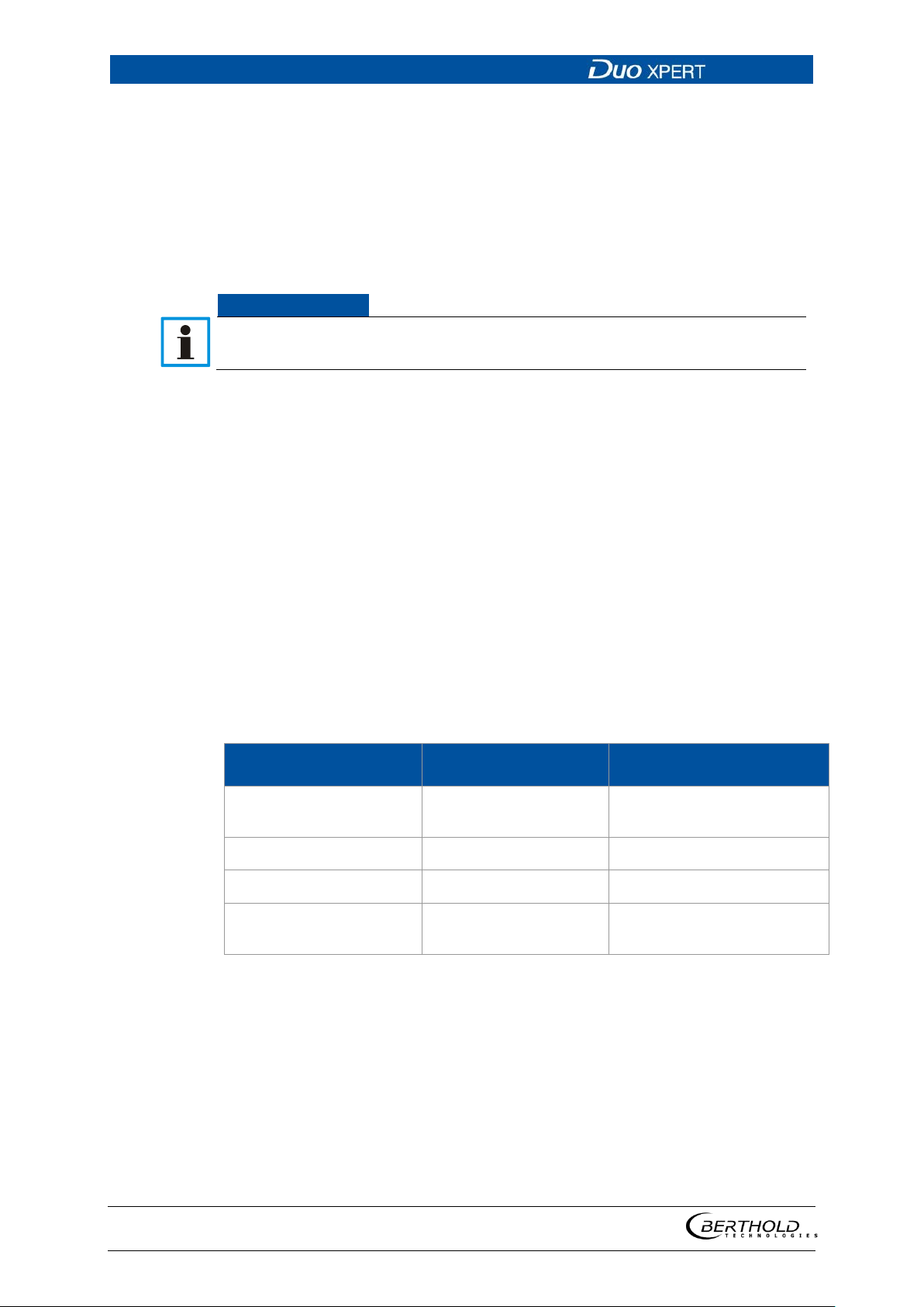
Field in the soft-
In the software description, the term "clicking" is used if a process is to be activated. This also refers to the pressing of a button or an area on the touch display
if a mouse is not used for control.
"Calibrate"
wareuser interface
Path specification Settings | Selection
Keys and buttons
Image reference Connect the plug (fig. 1,
item 1)
56925BA2 Rev. 03, 11/2017
Page 9
LB 470 Level 1 About this Operating Manual
9
Signal Word
Source and consequence
j DANGER
imminent
WARNING
potential
j CAUTION
potentially dangerous
1.8 23BWarning notes
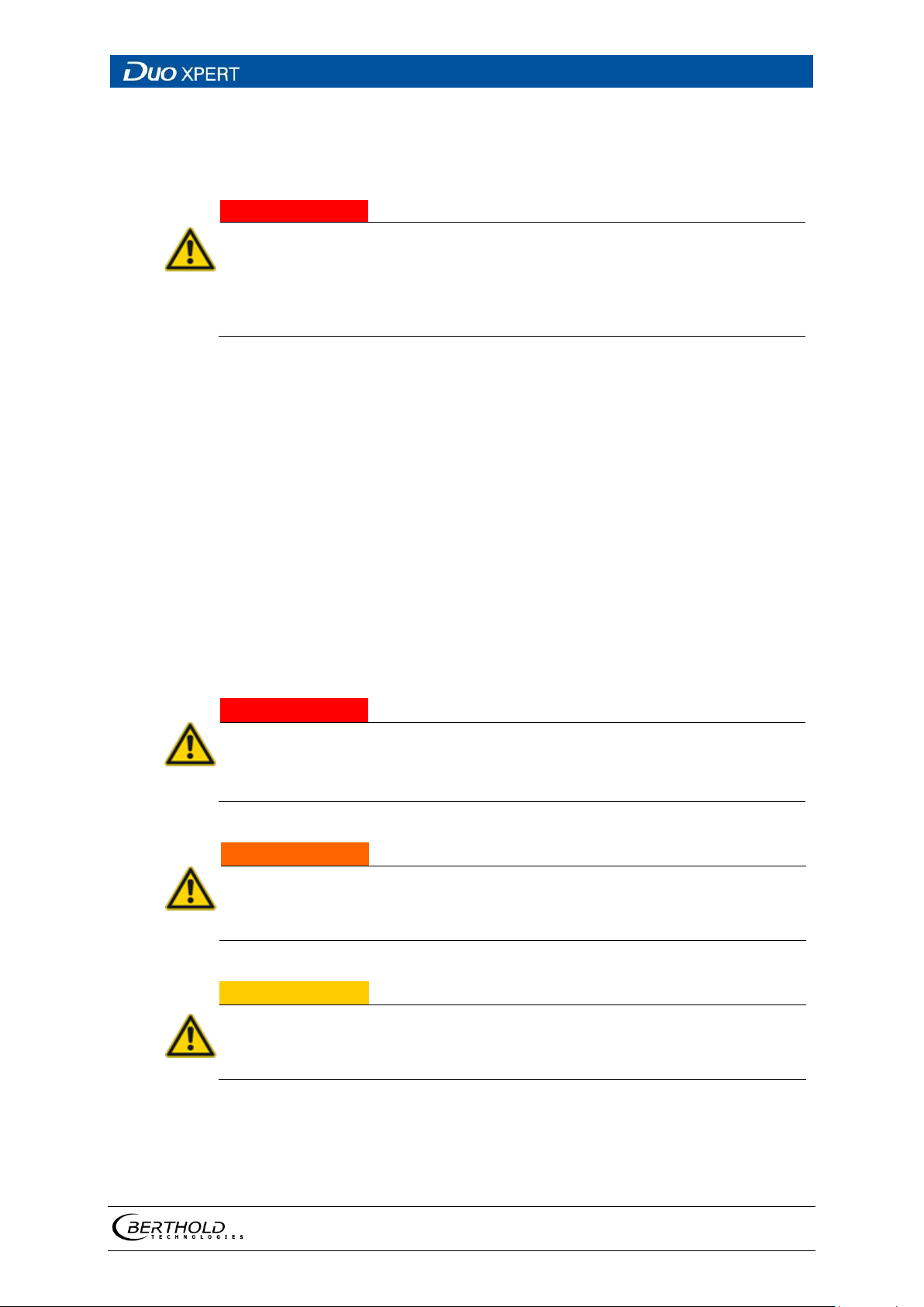
Warning notes are designed as follows:
Explanation, if required
Prevention
In case of emergency
• Warning symbols: (warning triangle) draws attention to the hazard.
• Signal word: Indicates the severity of danger.
• Source: Specifies the type or source of danger.
• Consequence: Describes the consequences of non-compliance.
• Prevention: Specifies how the hazard can be avoided.
• In case of emergency: Specifies which actions are required in the event of
the occurrence of risk.
1.8.1 72BSymbols Used in the Operating Manual
In this manual, warning instructions before instructions for action refer to risks of
injury or damage to property. The hazard-prevention measures described must be
observed.
Indicates an
juries or even death if the hazard is not avoided.
j
Indicates a
if the hazard is not avoided.
, major hazard, which will certainly result in serious in-
hazard, which can result in serious injuries or even death
Refers to a
minor physical injuries or damages to property, if it is not avoided.
56925BA2 Rev. 03, 11/2017
situation, which can result in medium or
Page 10
1 About this Operating Manual LB 470 Level
10
NOTICE
IMPORTANT
Tip
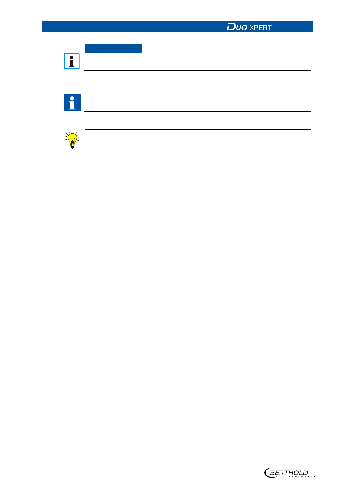
If this information is not observed, deterioration in the operation and/or property damage may occur.
Sections marked with this symbol point out important information on the
product or on handling the product.
Provides tips on application and other useful information.
56925BA2 Rev. 03, 11/2017
Page 11
LB 470 Level 1 About this Operating Manual
11
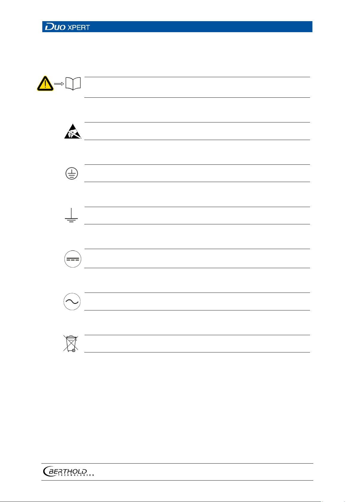
Read the operating manual
Electrostatic discharge
Protective earth connection
Equipotential bonding connection
Direct voltage
Alternating voltage
No domestic waste
1.8.2 73BSymbols Used on the Device
Please observe the instructions in this operating manual.
Please note the handling instructions. Electrostatically endangered components. Please observe the instructions in this operating manual.
At this position, connect the protective earth conductor (PE).
At this position, connect the equipotential bonding conductor.
The device is operated with direct voltage and may only be connected with a
direct voltage source.
The device is operated with alternating voltage and may only be connected
with an alternating voltage source.
The electric product must not be disposed of in domestic waste.
56925BA2 Rev. 03, 11/2017
Page 12

1 About this Operating Manual LB 470 Level
12
1.9 Conformity
The company BERTHOLD hereby declares in its sole responsibility that the design
of this product, which is brought to the market by BERTHOLD, complies with relevant EU directives stated in the original declaration of conformity.
This statement shall become void in the case of changes not authorised by
BERTHOLD or improper use.
For the original declaration of conformity, please refer to Declaration of Conformity in Technical Information.
56925BA2 Rev. 03, 11/2017
Page 13

LB 470 Level 2 Safety
13
2 Safety
2.1 Dangers and safety measures
• Read these instructions thoroughly and completely before working with the
product.
• Store the instructions where they are accessible for all users at all times.
2.2 Proper Use
The evaluation unit DuoXpert LB 470 (EVU) measures the level together with compatible detectors and an appropriate radiation source and may only be used for
this purpose.
The following constitutes proper use:
• Adhering strictly to the instructions and operation sequences and not un-
dertaking any different, unauthorised practices which could endanger your
safety and the operational reliability of the EVU!
• Observing the given safety instructions!
• Carrying out the prescribed maintenance measures or having them carried
out for you!
• Only use accessories and spare parts from BERTHOLD.
56925BA2 Rev. 03, 11/2017
Page 14
2 Safety LB 470 Level
14
NOTICE
NOTICE
Improper use to be prevented:
• Failing to observe the specified safetyinstructions and instructions for the
operation, maintenance and disposal in the operating manual.
• Any non-compliance with the present operating manual for the supplied
products.
• Applying conditions and requirements which do not conform to those
stated in the technical documents, data sheets, operation manuals and assembly instructions and other specific guidelines of the manufacturer.
• Use of the product if parts of it are damaged or corroded. This also applies
for seals and used cables.
• Restructuring or changing the system components.
• The product is not suitable for use in potentially explosive areas and may
therefore not be operated in such areas. The product is not explosion-proof.
• Operation ...
o in a state where live parts are accessible.
o in a wall housing with inadequately sealed glands and / or insufficiently
tightened or damaged cable glands.
• Operation without the safety precautions provided by the manufacturer.
• Manipulation or avoidance of existing safety equipment.
BERTHOLD shall only accept liability for / guarantee the correspondence of the device to its publicised specifications.
If the product is used in a way which is not described in the present operating
manual, the device's protection is compromised and the warranty claim becomes
invalid.
The device is not approved according to IEC 61508 “Functional safety of safetyrelated electric/electronic/programmable electronic systems”.
2.3 Qualification of the Personnel
A minimum requirement for all work on or with the product would be employees with general knowledge who are instructed by an expert or authorised
person.
At different parts in this operating manual, reference is made to groups of people
with certain qualifications who can be entrusted with different tasks during installation, operation and maintenance.
These three groups of people are:
• Employees with General Knowledge
• Experts
• Authorised Persons.
56925BA2 Rev. 03, 11/2017
Page 15
LB 470 Level 2 Safety
15
NOTICE
Employees with General Knowledge
Employees with general knowledge must always be guided by an expert at
the very least. When dealing with radioactive substances, a radiation safety
officer must also be consulted.
Employees with general knowledge are e.g. technicians or welders, who can undertake different tasks during the transportation, assembly and installation of the
product under the guidance of an authorised person. This can also refer to construction site personnel. The persons in question must have experience in handling
the product.
Experts
• Experts are persons who have sufficient knowledge in the required area due
to their specialist training and who are familiar with the relevant national
health and safety regulations, accident prevention regulations, guidelines
and recognised technical rules.
• Expert personnel must be capable of safely assessing the results of their
work and they must be familiar with the content of this operating manual.
Authorised Persons
Authorised persons are those who are either designated for the corresponding task
due to legal regulations or those who have been authorised by BERTHOLD for particular tasks. When dealing with radioactive materials, a radiation safety officer
must also be consulted.
56925BA2 Rev. 03, 11/2017
Page 16

2 Safety LB 470 Level
16
2.4 Operator's Obligations
The operator of the product must regularly train his personnel in the following
topics:
• Observation and use of the operating manual and the legal provisions.
• Intended operation of the product.
• Observation of the plant security instructions and the operating instructions
of the operator.
• Regular monitoring/maintenance of the product.
56925BA2 Rev. 03, 11/2017
Page 17
LB 470 Level 3 System Description
17
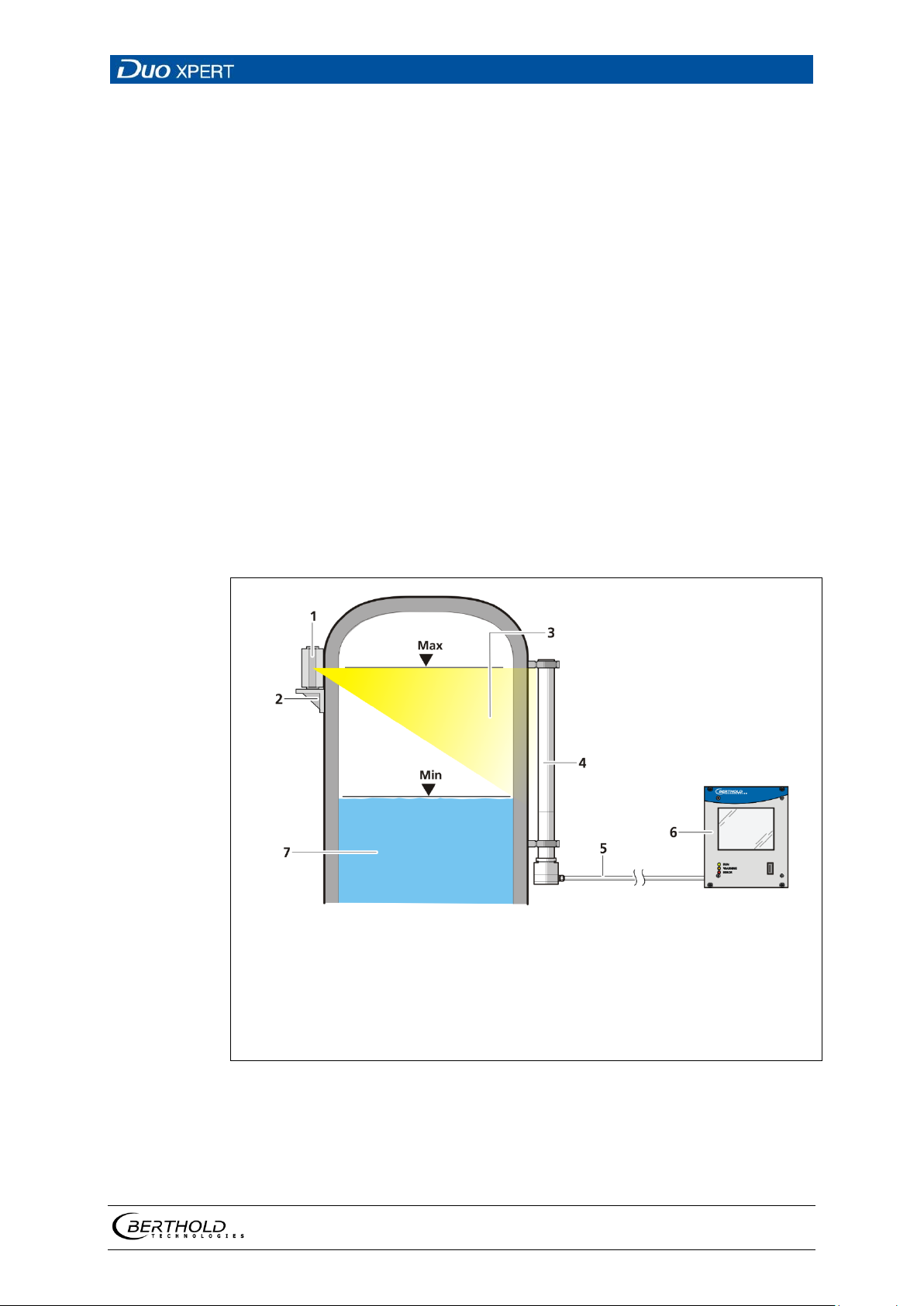
1
2
3
4
5
6
7
Point source shield
Mounting base
Radiation beam
Rod detector
Measurement line to master EVU
Master EVU
Product
Fig.
3 System Description
3.1 Overview
The level measuring device LB 470 is an industrial measuring system for the contactless and continuous determination of the level of a product in a container.
A complete measuring system consists of the following components:
• Evaluation unit DuoXpert LB 470
• Source
• Shields
• Point detector / rod detector(s)
These instructions concern the operation of the evaluation unit DuoXpert LB 470
(Fig. 1, item 6). The operation of other system components is part of the independent instructions of the respective system components.
The EVUs are standard equipment in switch rooms with 19" subracks or switchboards.
1 Example measurement arrangement
56925BA2 Rev. 03, 11/2017
Page 18
3 System Description LB 470 Level
18
Tip
3.2 Measuring Principle
Gamma radiation is used to penetrate a medium in a container. The attenuation
of the radiation is analysed to measure the level in the container.
The evaluation DuoXpert LB 470 (master EVU) is used for the evaluation, transmission and visualisation of measured values which it receives from the connected
detectors.
The EVU is an independent measurement channel. If several measurement channels are required, an independent EVU must be used for each channel.
For covering larger measuring ranges with level measurements, it is possible to
connect multiple detectors on a level measuring device LB 470. To do this, an additional slave module is required (optional) for each additional detector after the
first. A maximum of 16 slave modules can be connected per master EVU. A cascaded
measurement system with a maximum of 17 detectors can be set up in this way.
Further information on the functional principle of the detectors can be found
in the operating manual.
56925BA2 Rev. 03, 11/2017
Page 19
LB 470 Level 3 System Description
19
1
2
3
4
5
6
7
8
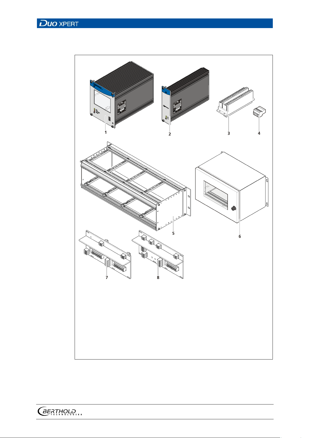
Master-EVU with wide range supply (100-240V AC, 50/60 Hz)
Slave module with wide range power supply (optional)
Clamp block for electrical connections (optional)
Master/Slave connector
19" subrack (optional)
Wall housing (optional)
Backplane Master-Master with cover
Backplane Master-Slave with cover
Fig.
3.3 System Components
Alternatively: Master-EVU with 24V supply (18-32V DC)
Alternatively: Slave module with 24V supply (optional)
only for installation in subrack / switchboard)
56925BA2 Rev. 03, 11/2017
2 System components
Page 20

3 System Description LB 470 Level
20
3.3.1 74BSoftware
The EVU is delivered with pre-installed software. The revision status (version) of
the software can be seen on the screen display when starting up the EVU or in the
menu "Device information" (Chapt. 7.1.2 ).
This operating manual describes the software version 1.3.0
(Control Unit / CU) and 1.3.0 (Measurement Unit / MU).
56925BA2 Rev. 03, 11/2017
Page 21
LB 470 Level 3 System Description
21
1
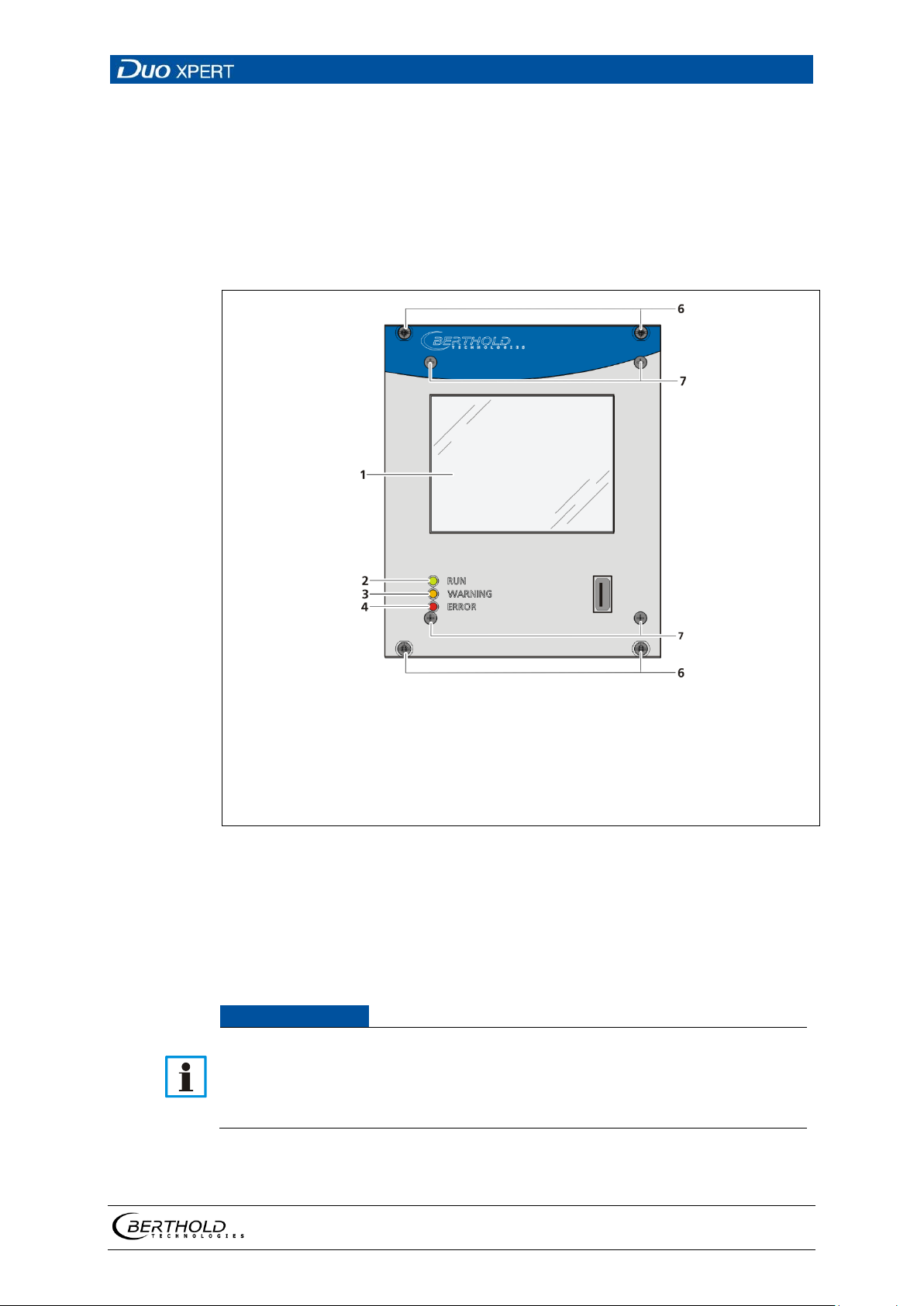
2
3
4
5
6
7
3.5'' Touch display
RUN LED
WARNING LED
ERROR LED
USB port
Mounting screws
Screws front plate
Fig.
NOTICE
Damage to the touch screen
3.3.2 75BFront/rear view master EVU
Front view master EVU
The following control elements are found on the front of the master EVU:
• LEDs for status display of individual operating states
• 3.5'' Touch display
• USB port.
3 Back view of the master EVU
Operation Display / Touch Screen
The EVU is operated via the touch screen. Alternatively, the device can be connected to a mouse at the USB port. The device can also operated by remote control
(see chap. 7.3.1).
Pointed or sharp objects can damage the plastic surface of the touchscreen.
Operate the touch screen only with your fingers or with a touch pen or con-
nect a mouse.
56925BA2 Rev. 03, 11/2017
Page 22
3 System Description LB 470 Level
22
Display LED
Description
RUN
RUN
RUN (flashing)
WARNING
WARNING
ERROR
ERROR
RUN / WARNING / ERROR flashing
Status displays of the master EVU
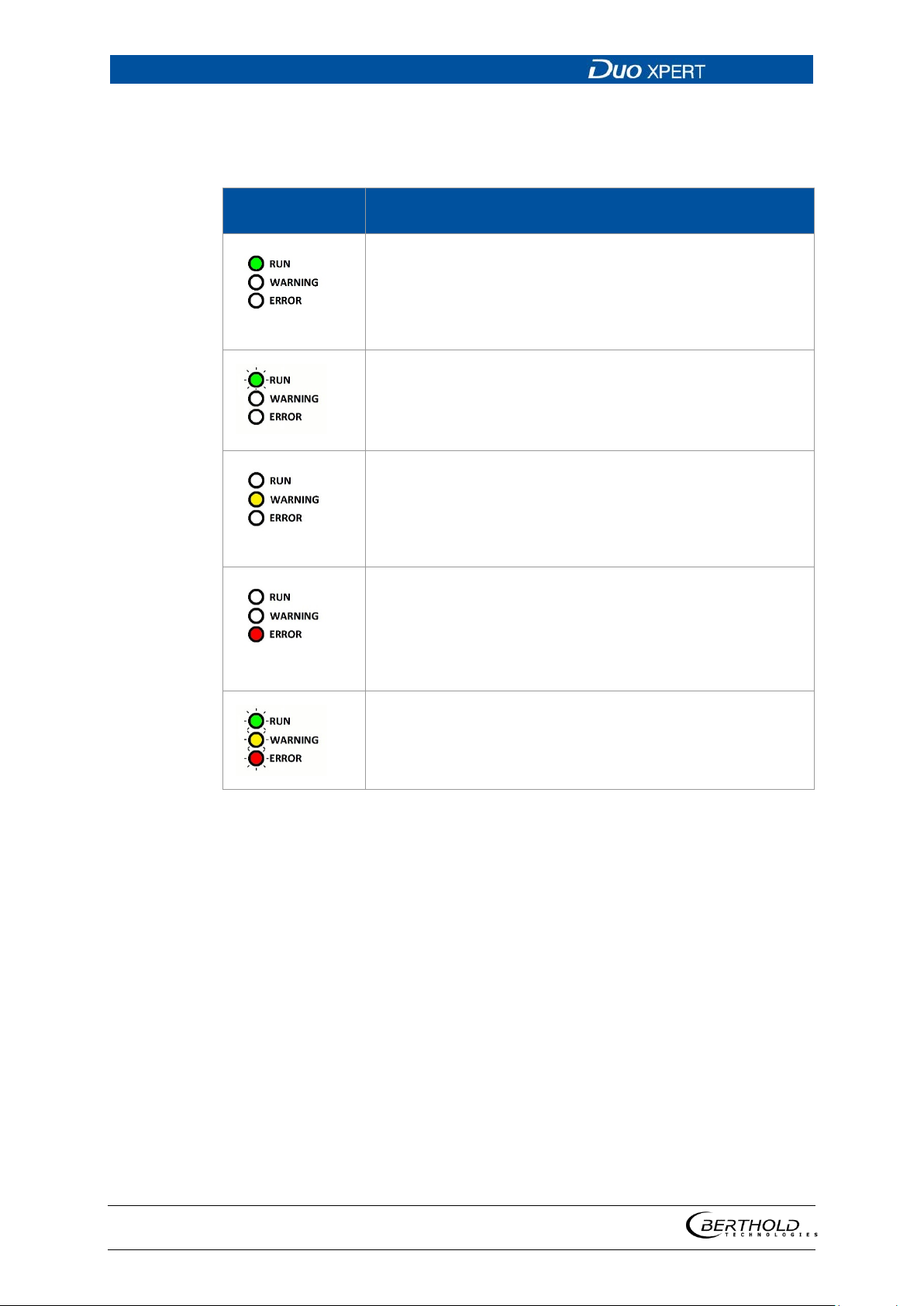
The LEDs (fig.1, items 2-4) below the touch display show the current operating status of the master EVU.
This LED lights up green if the device is in operation
and fault-free. The current measurement is carried out.
The RUN LED flashes green while the measurement is
(held) in the STOP state by user actions (e.g. stop function, simulation mode, plateau recording).
This LED lights up yellow when a system event
of the type "Outside of specification", "Maintenance required" or "Function check" is present.
All system events are described in chapter 8.
This LED lights up red if a system event of the type "Failure" is present. The current measurement is retained.
Check the device settings.
All system events are described in chapter 8
All three LEDS flash during the system test which is performed as part of the start up process.
56925BA2 Rev. 03, 11/2017
Page 23
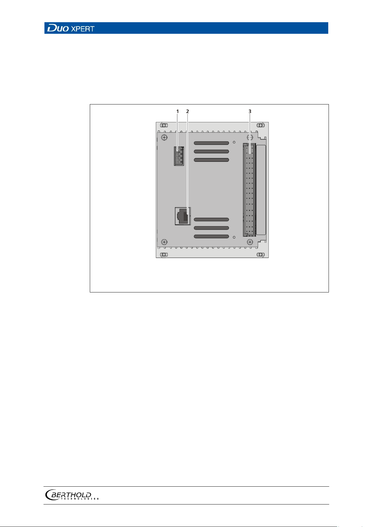
LB 470 Level 3 System Description
23
1
2
3
Master/slave 4-pin connector
RJ45 socket for Ethernet
32-pin plug connector
Fig.
Rear view master EVU
The following connections are located on the back of the EVU:
• Master/slave connector, 4-pin
• RJ45 socket for Ethernet
• 32-pin plug connector
4 Front/rear view master EVU
56925BA2 Rev. 03, 11/2017
Page 24
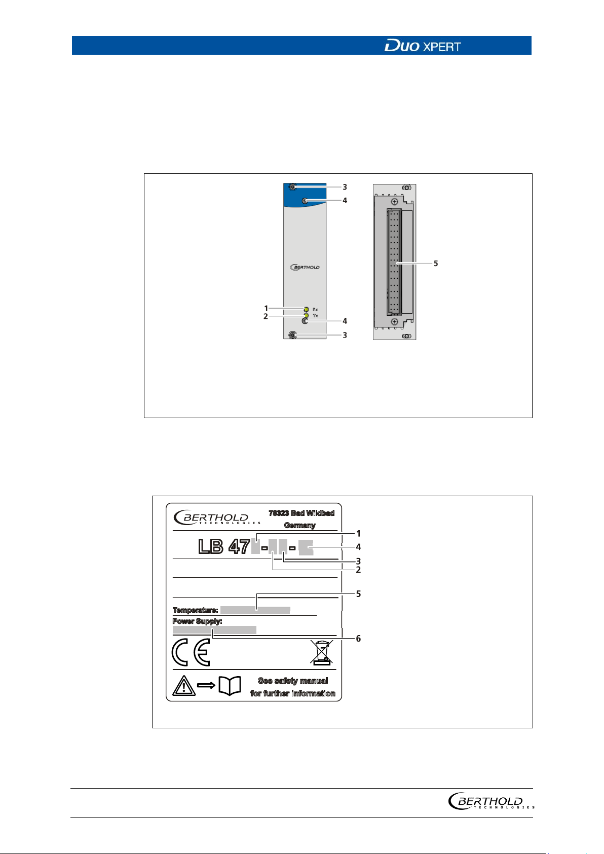
3 System Description LB 470 Level
24
1
2
3
4
5
LED Rx
LED Tx
Mounting screws
Screws front plate
32-pin plug connector
Fig.
1
2
3
4
5
6
Application (0 = level)
Approval explosion pro-
tection (0 = no explosion
approval)
Power supply
(1 = 24V DC; 2=100…24V
AC -10 +10%)
Master (M) or slave (S)
permissible temperature
range for operation (ambient temperature)
Power specifications
Fig.
3.3.3 76BFront/rear view slave module
The LEDs Rx and Tx are found on the front of the slave module.
The LED Rx flashes green when data is received.
The LED Tx flashes green when data is sent.
The 32-pin plug connector is found on the back side.
5 Front/rear view slave module
3.3.4 77BType plate
56925BA2 Rev. 03, 11/2017
6 Type plate
Page 25
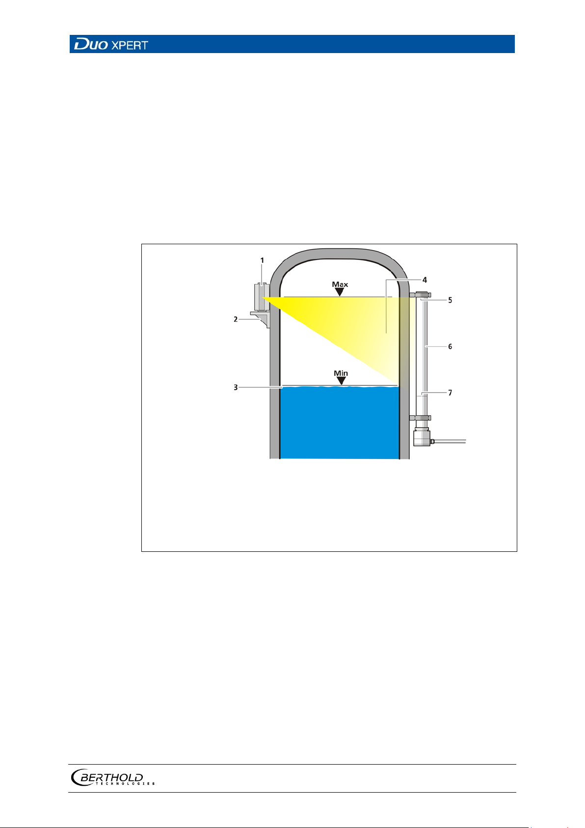
LB 470 Level 3 System Description
25
1
2
3
4
5
6
7
Point source / shield
Mounting base with source
Level
Radiation field
Upper marking groove
Rod detector
Lower marking groove
Fig.
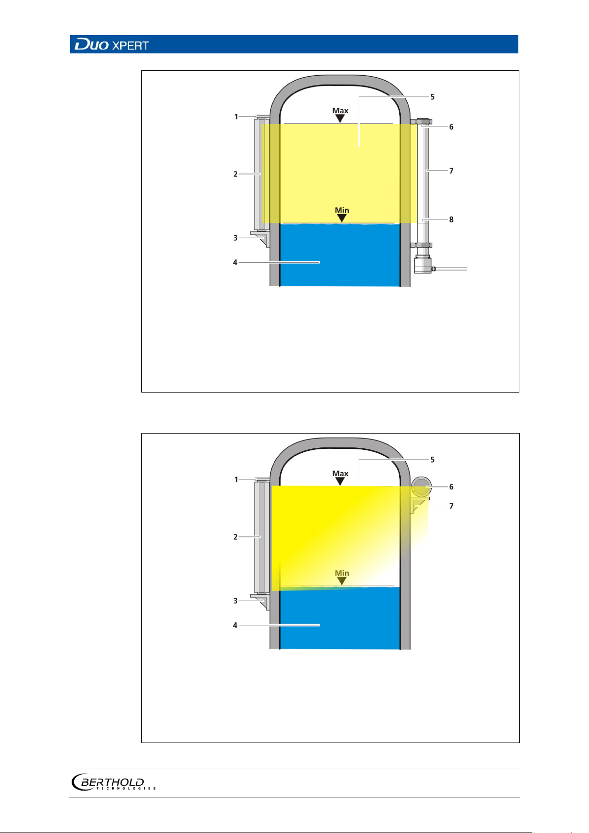
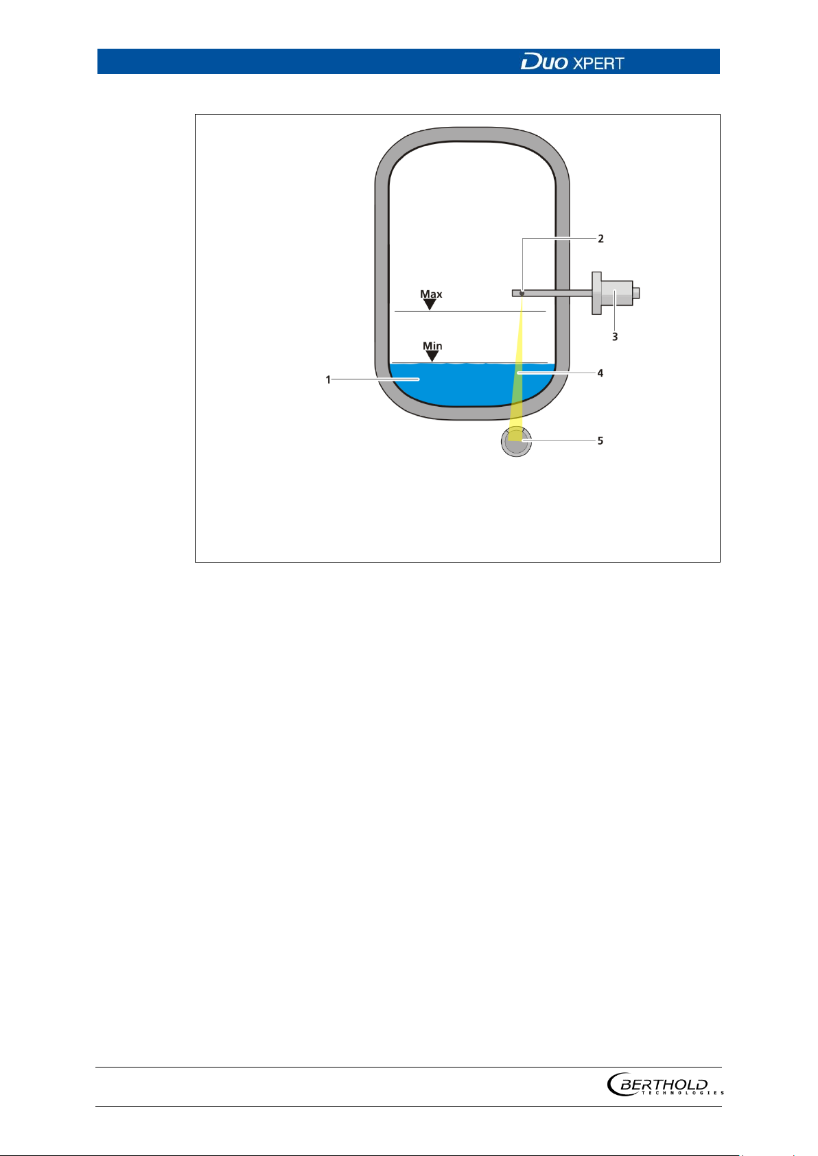
3.4 Measurement arrangements
The detector and/or the source are rod-shaped for a radiometric level measurement, so as to form a triangular or rectangular useful beam field. The change of
the measurement signal
of the radiation field.
The marking grooves on the detector housing highlight the sensitive area of the
detector. The detector must be mounted on the container so that the desired
measuring range is covered by the sensitive area.
In a cascaded system (with multiple detectors), the lower marking groove of the
1st detector must match the upper of the 2nd detector etc. (Fig. 8).
for different level results from the different sized covering
7 Schema Point source - rod detector
3.5 Storage
Keep devices in a dry (no condensation), dark (no direct sunlight), clean and lockable room. Stay within the temperature range for storage.
56925BA2 Rev. 03, 11/2017
Page 26
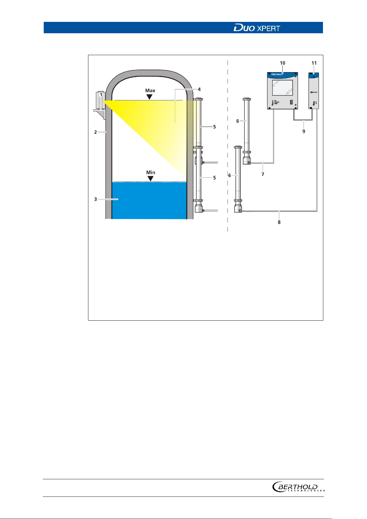
3 System Description LB 470 Level
26
1
2
3
4
5
6
7
8
9
10
11
Point source / shield
Mounting base with source
min / max level
Radiation field
Rod detector 1 + 2
Rod detector 1 + 2 (side view)
Measurement line (1st detector - master EVU)
Measurement line (2nd detector - slave module)
Connection master EVU - slave module
Master EVU
Slave module
Fig.
8 Schema Point source-rod detector cascaded
56925BA2 Rev. 03, 11/2017
Page 27
LB 470 Level 3 System Description
27
1
2
3
4
5
6
7
8
Mounting base
Rod source / shield
Mounting base with source
Min/max level
Radiation field
Upper marking groove
Rod detector
Lower marking groove
Fig.
1
2
3
4
5
6
7
Mounting base
Rod source / shield
Mounting base with source
Min/max level
Radiation field
Detector
Mounting base
Fig.
9 Schema Rod source - rod detector
56925BA2 Rev. 03, 11/2017
10 Schema Rod source - point detector
Page 28
3 System Description LB 470 Level
28
1
2
3
4
5
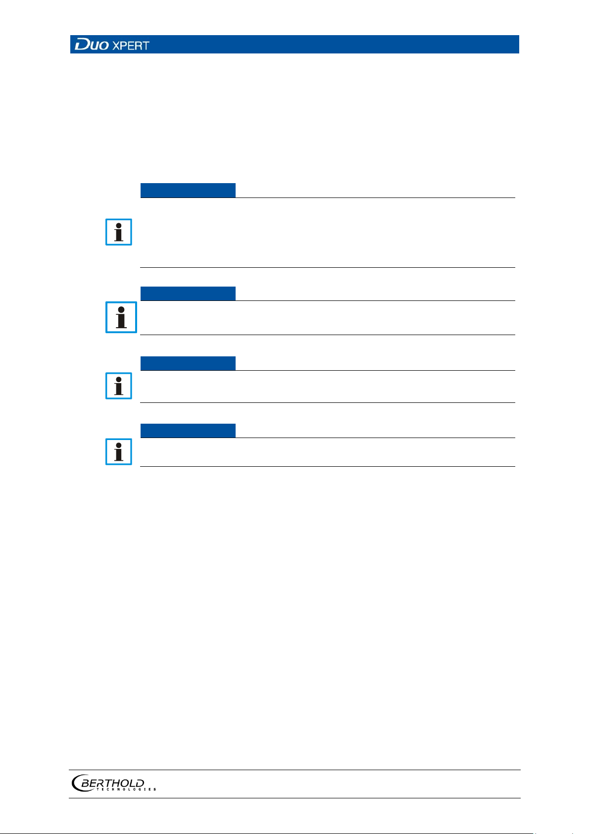
Min / max level
Point source in the dip tube
Shield
Radiation beam
Detector
Fig.
11 Schema point source - point detector (absorption level measurement)
The detector and the source are usually formed as points in an absorption level
measurement.
Based on the arrangement of source and detector (Fig. 11), the change in the measurement signal results from the different material thickness of the product being
measured.
56925BA2 Rev. 03, 11/2017
Page 29
LB 470 Level 4 Installation
29
NOTICE
NOTICE
NOTICE
NOTICE
4 Installation
4.1 General Instructions
The applicable national regulations of the country of use have to be observed!
Repair and maintenance on the devices may only be performed by experts
(see chapter 2.3).
In case of doubt, the complete device must be returned to BERTHOLD for re-
pair.
The Evaluation unit is not explosion protected and is not designed for
hazardous environments.
Only mounting accessories approved by BERTHOLD should be used for installation of the devices.
The device should only be operated if firmly installed.
4.2 Unpacking/Scope of Delivery
The product will be delivered completely configured according to the purchase order. Check your delivery for completeness and damage according to your order.
Please report missing, defective or incorrect parts immediately.
56925BA2 Rev. 03, 11/2017
Page 30
4 Installation LB 470 Level
30
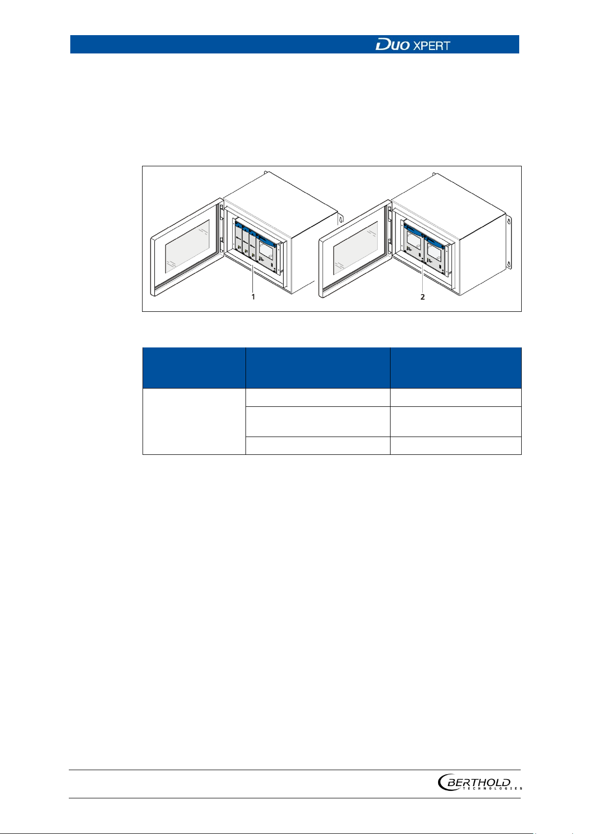
Fig.
Installation
variant
Connection
Components
,
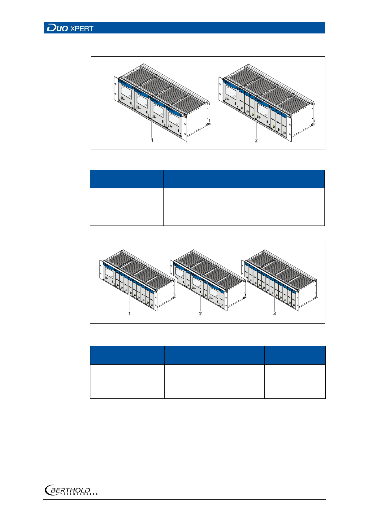
4.3 Installation variants
The modules can be installed either in wall housings (Fig. 12) or 19" subracks (Fig.
13).
Installation variants wall housing
12 Installation variants wall housing
Wall housing
Terminal panel master 2 Master (Fig. 12, item 2)
Terminal panel master/slave
Clamp blocks 2 Master (Fig. 12, item 2)
1 Master, 3 Slaves (Fig. 12
item 1)
56925BA2 Rev. 03, 11/2017
Page 31
LB 470 Level 4 Installation
31
Fig.
Installation variant
Connection
Components
Fig.
Installation variant
Connection
Components
Installation variants subrack
13 Installation variants 19" subrack with terminal panel
2 terminal panel master (Fig. 13,
19" subrack
item 1)
2 terminal panel master/slave (Fig.
13, item 2)
14 Installation variants 19" subrack with clamp blocks
6 clamp blocks (Fig. 14, item 1) 3 Master, 3 Slaves
4 Master
2 Master, 6
Slaves
19" subrack
10 clamp blocks (Fig. 14, item 2) 1 Master, 9 Slaves
12 clamp blocks (Fig. 14, item 3) 12 Slaves
56925BA2 Rev. 03, 11/2017
Page 32
4 Installation LB 470 Level
32
NOTICE
1
2
3
4
Master-slave connector
Socket board
Guide rails
Fixing screws
Fig.
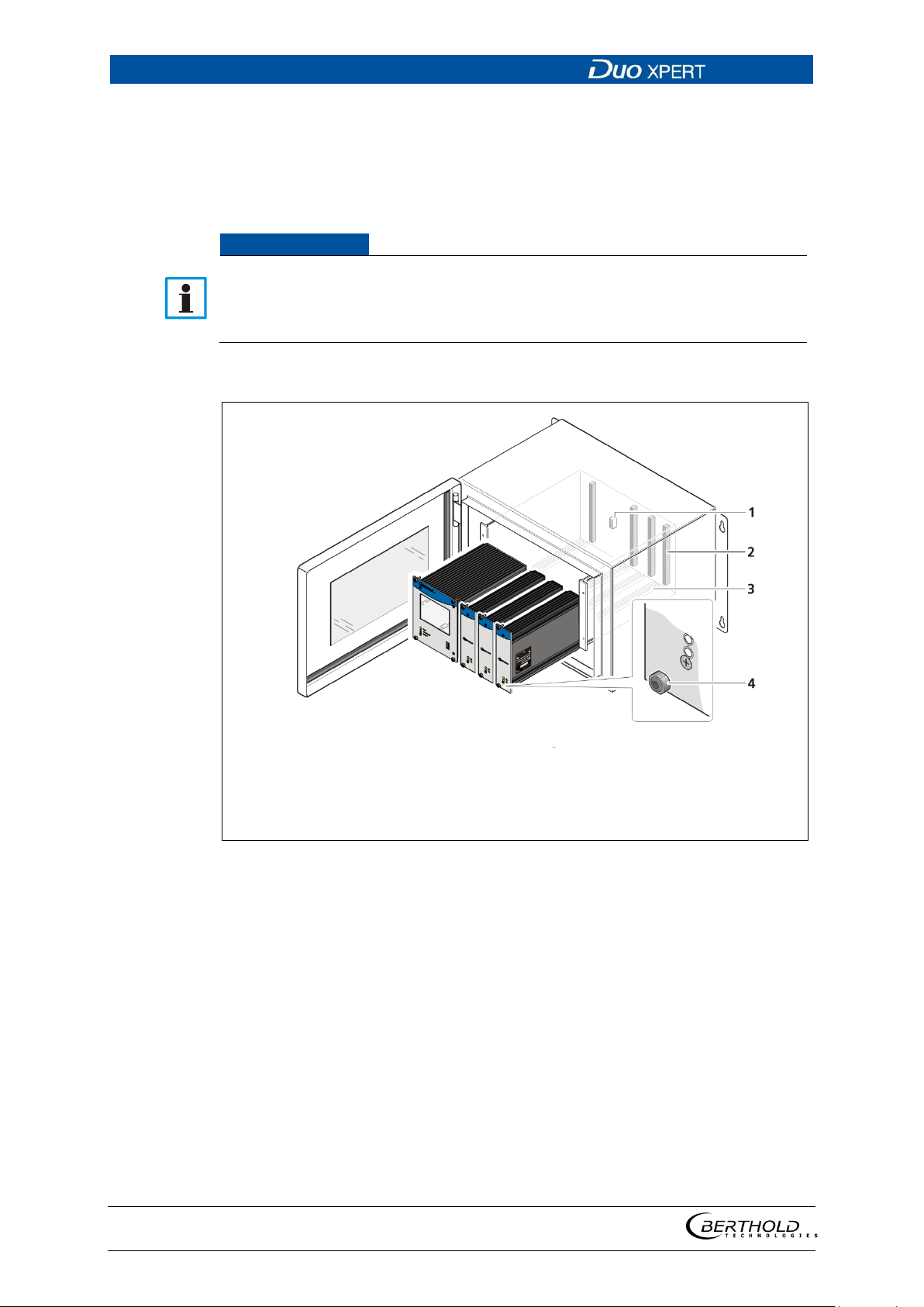
4.3.1 78BInstallation in the wall housing
The wall housing may be equipped differently, depending on requirements (see
chap. 4.3 Installation variants). To do this, a corresponding terminal panel is located
in the wall housing.
The master EVUs / slave modules must be secured against pulling out by fixing
screws (Fig. 15, item 4).
The device must be disconnected from the mains voltage before it is pulled
out.
Installation of the modules (master-slave)
15 Installation of the modules (master-slave)
1. Set modules into the guide rails and push it gently until the plug connector
of the module (
Fig. 15, item 2) is inserted into the socket board.
2. Tighten all fixing screws (Fig. 15, item 4).
56925BA2 Rev. 03, 11/2017
Page 33
LB 470 Level 4 Installation
33
1
2
3
4
Master-slave connector
Socket board
Guide rails
Fixing screws
Fig.
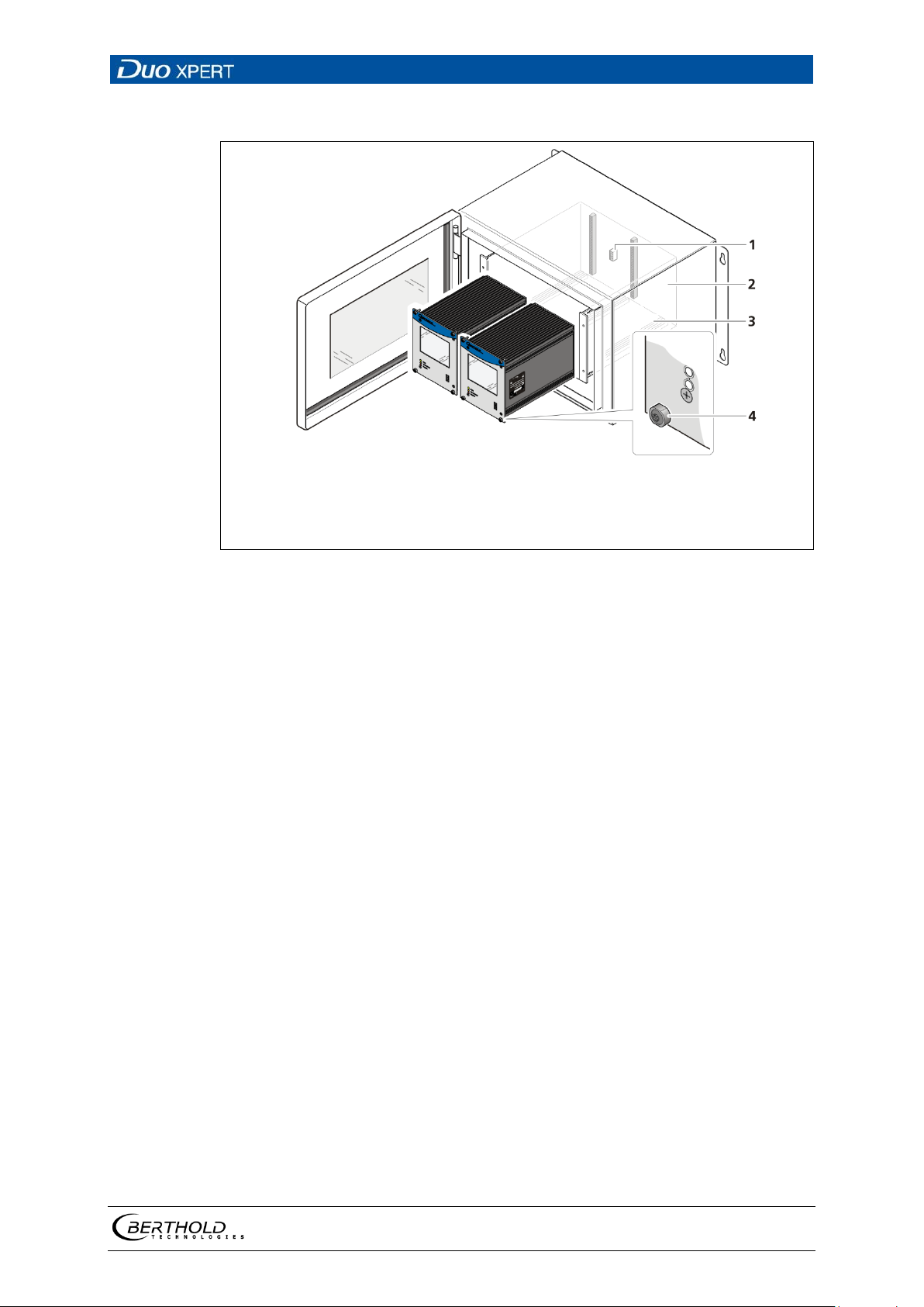
Installation of the modules (master-master)
16 Installation of the modules (master-master)
1. Set modules into the guide rails and push it gently until the plug connector
of the module (
2. Tighten all fixing screws (Fig. 16, item 4).
Fig. 16, item 2) is inserted into the socket board.
56925BA2 Rev. 03, 11/2017
Page 34
4 Installation LB 470 Level
34
Fig.
NOTICE
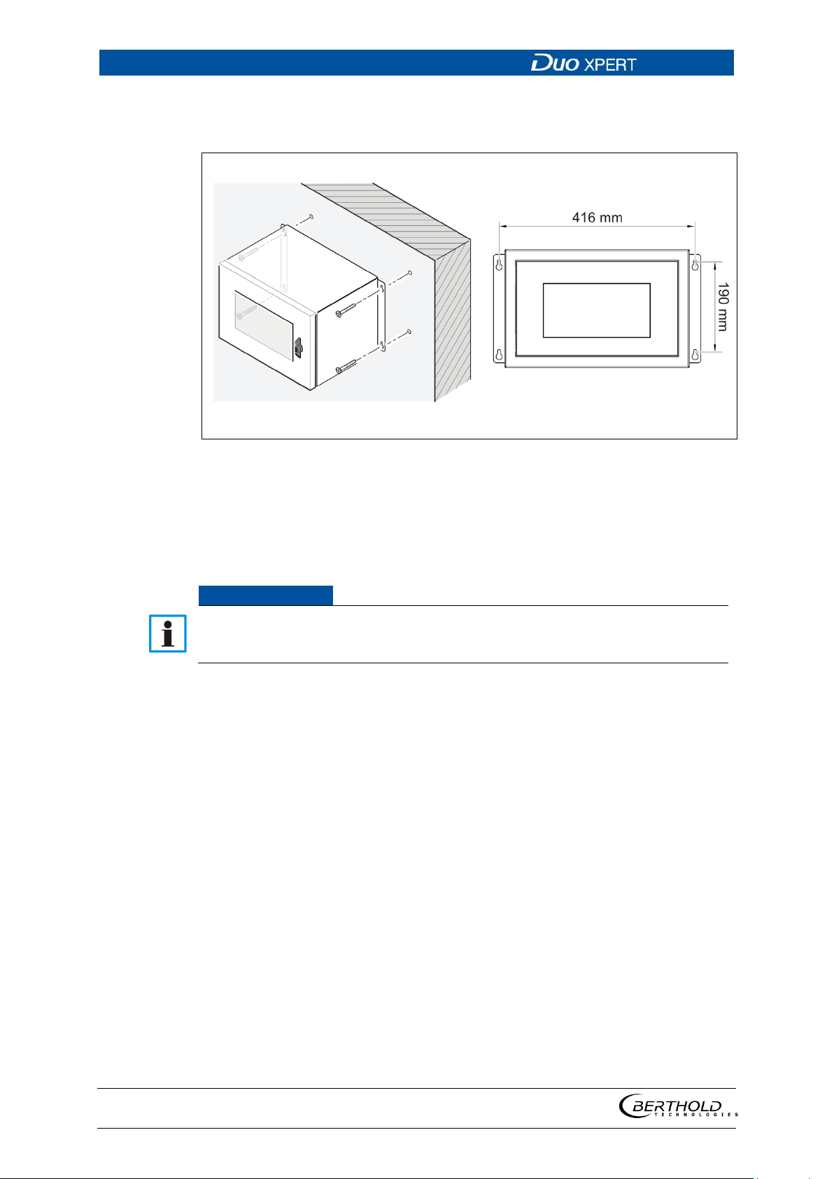
Mounting the wall housing
4 holes (Fig. 17) are provided for mounting on the wall etc.
17 Mounting the wall housing
1. Prepare the holes.
2. Use adequately dimensioned mounting material.
3. Screw the housing securely to the wall.
It is recommended that the wall housing be protected from direct sunlight in
order to maintain maximum ambient temperature (see appendix “Technical
Information”).
56925BA2 Rev. 03, 11/2017
Page 35
LB 470 Level 4 Installation
35
NOTICE
NOTICE
4.3.2 79BInstallation in the 19" subrack
The 19" subrack can be equipped differently, depending on requirements (see
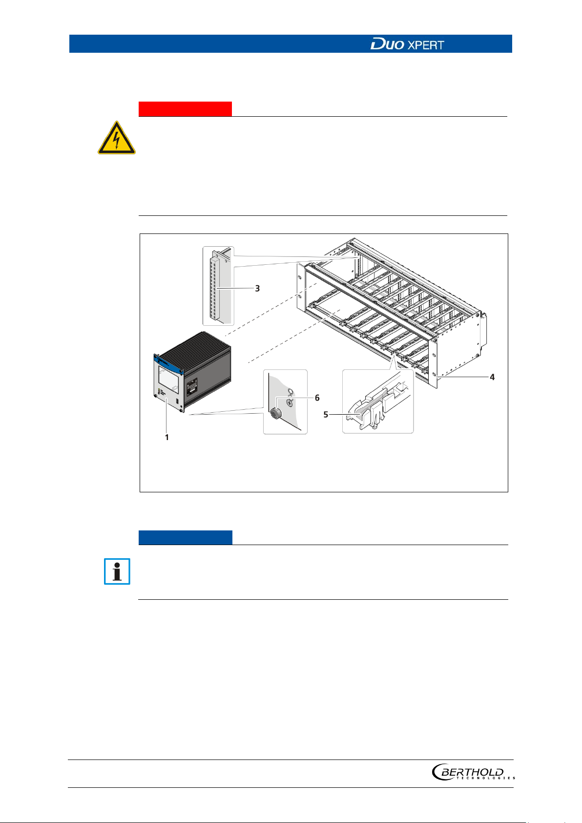
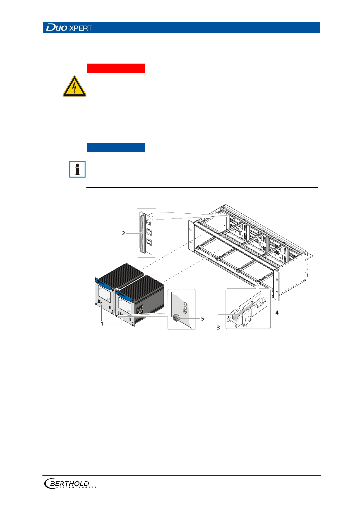
chap. 4.3 Installation variants). The rear clamp blocks (Fig. 18, item 3) or terminal
panels (Fig. 19, item 4) are used for the electrical connection.
The 19" subrack may only be installed in a dry environment.
The subrack is installed in a 19" control cabinet or a control panel (switchboard).
The 4 side holes (Fig. 19, item 4) that should be provided with fitting screws are
used to fasten the subrack.
The EVU is delivered equipped, depending on the order. The installation of
the modules is only necessary if:
Another measurement channel is to be fitted
A defective module is to be replaced
56925BA2 Rev. 03, 11/2017
Page 36
4 Installation LB 470 Level
36
j DANGER
Danger to life from electric shock!
In case of an electric shock, carry out first aid measures and immediately call an emergency service.
1
2
3
Master EVU
Slave module
Clamp block
4
5
6
Drilling
Guide rail
Fixing screw
Fig.
NOTICE
Installation with clamp blocks
Installation/maintenance may only be carried out if the device has been
de-energised.
Test of absence of harmful voltages when the front side is open.
18 19" subrack with clamp block (Ex: 1x Master, 9xSlave)
The master's EVUs / slave modules must be secured against pulling out by fixing screws (Fig. 18, item 6).
The device must be disconnected from the mains voltage before it is pulled
out.
1. Set master EVU / slave module (Fig. 18, item 1, item 2) in the guide rails (Fig.
18, item 5).
2. Carefully slide module into the subrack until the plug connector is inserted
into the clamp block.
3. Tighten fixing screws (Fig. 18, item 6).
56925BA2 Rev. 03, 11/2017
Page 37
LB 470 Level 4 Installation
37
j DANGER
Danger to life from electric shock!
In case of an electric shock, carry out first aid measures and immediately call an
emergency service.
NOTICE
1
2
3
Master EVU
Socket board terminal panel
Guide rails
4 5 Drilling
Fixing screws
Fig.
Installed with terminal panels
Installation/maintenance may only be carried out if the device has been
de-energised.
Test of absence of harmful voltages when the front side is open.
The master's EVUs / slave modules must be secured against pulling out by fixing screws (Fig. 19, item 5).
The device must be disconnected from the mains voltage before it is pulled
out.
19 19" subrack with terminal panel (Ex.: 4x master)
1. Set master EVU / slave module (Fig. 19, item 1) into the guide rails (Fig. 19,
item 3).
2. Carefully slide module into the subrack until the plug connector is inserted
into the socket board (
Fig. 19, item 2).
3. Tighten fixing screws (Fig. 19, item 5).
56925BA2 Rev. 03, 11/2017
Page 38
5 Electric Installation LB 470 Level
38
j DANGER
Danger to life from electric shock!
In case of an electric shock, carry out first aid measures and immediately call an emergency service.
NOTICE
NOTICE
5 Electric Installation
5.1 General Instructions
The installation may only be carried out by a qualified electrician.
Please adhere to the relevant safety regulations.
Open the housing only in a dry environment and for installation, mainte-
nance and servicing.
During installation and servicing on the hardware as well as during wiring
of the detector, the measuring system, connected relay contacts and all inputs and outputs must be de-energised.
Connect only devices onto the product that comply with the applicable
safety standards.
Apply the voltage of the specified and marked range only!
The relay of the LB 470 can only switch low voltages. Please note the specifications in appendix Technical Information.
The power source of 24 V DC version of the product must meet the requirements of the
Low Voltage Directive and be equipped with double or reinforced insulation.
The voltage parameters of all devices connected to the outputs of the product (e.g. relay
circuit, RS-485, current output) must comply with the limit values of the safety directives
for electrical measurement, control, regulation and laboratory devices (DIN EN 61010-1)
and be equipped with double or reinforced insulation.
These protective measures are necessary to avoid the risk of contact with life-threatening
voltages.
Changing the installation without precise knowledge of this operating manual is
not permitted.
56925BA2 Rev. 03, 11/2017
Page 39

LB 470 Level 5 Electric Installation
39
IMPORTANT
General important points for installation
Connect the earth conductor.
Ground the housing.
Please observe the information signs on the devices.
5.1.1 80BCircuit Breaker
A circuit breaker according to DIN EN 61010-1
• must be available,
• must be easily accessible for the maintenance personnel and
• is to be included in the company-internal documentation.
The master EVUs / slave modules are not equipped with a separate ON/OFF switch
to connect or disconnect the voltage supply. Make sure that the system can be deenergised via the external power supply.
The circuit breaker can be installed as an automatic fuse or switch and has to comply with the requirements according to IEC 947-1 and IEC 947-3. If a fuse is applied,
it must not be triggered under a current strength of 4 A per device.
The circuit breaker must be located near the device and be properly marked as
belonging to it.
5.1.2 81BCables and Lines
Lines are to be connected with special care.
Connection lines and routing must comply with the applicable regulations.
When routing the cables, make sure that the cable insulation cannot be me-
chanically damaged by sharp edges or movable metal parts.
Use the approved BERTHOLD cable or a cable with equivalent specifications
for the connection.
For intrinsically safe systems, the detector must be connected to the equipotential
bonding of the system. The detector is connected via a 2-core (2 x 12) cable with
approx. 5 ... 10 mm diameter. A screened cable can be used in systems with extremely strong electrical noise. The screen may only be laid out on one side of the
detector. The maximum cable length depends on the cable resistance, which may
not exceed a total (there and back) of 40 ohms. For standard cables from
BERTHOLD TECHNOLOGIES (Id. no. 32024), this results in a cable length of 1000m,
from the evaluation unit to the detector. For intrinsically safe systems, the maximum permissible inductance and capacitance of the cable should be considered to
the max. 40 ohm.
56925BA2 Rev. 03, 11/2017
Page 40

5 Electric Installation LB 470 Level
40
When routing the connection lines, make sure that
no dirt or moisture reaches the connection room,
the conductors are not damaged when the cable insulation is removed,
the conductor insulation or the sleeve of the wire end ferrules reach into the
housing of the terminal unit,
blank, conductive segments of the lines (e.g. wires of a litz wire) do not
reach outside the terminal unit,
the wire end ferrule or the stripped wire have a length of 8 mm so that the
wire is held securely in the clamp,
the line insulation reaches into the sleeve of the wire end ferrule if these
components are used,
the admissible minimum bending radius for the respective line cross-section
is not exceeded and
the cables are laid out in a strain-relieved and friction-free manner.
Only use cables whose diameters are approved for the respective cable
gland. The cables must comply with the requirements and cross-sections specified in the technical data.
The connected cables must be appropriate for temperatures of at least 10°C
above the maximum admissible ambient temperature.
5.1.3 82BCable Glands and Blanking Elements
The feeding of cables into the wall housing is only permitted via a cable en-
try.
Cable glands must be suitable for the respective application.
All cable glands must be assembled according to manufacturer's instructions
and be tightened to the appropriate tightening torque.
Cable glands that are not required for installation must be covered with suit-
able blanking elements.
Line cross-sections must comply with the respectively used cables.
Cable bushings and blanking elements must comply with the applicable IP
protection class and with the requirements for the operational environment.
We recommend ordering missing cable glands, blanking elements or adapt-
ers from BERTHOLD.
56925BA2 Rev. 03, 11/2017
Page 41

LB 470 Level 5 Electric Installation
41
5.1.4 83BProtective earth and equipotential bonding
The protective earth conductor has to be connected to the terminals marked
with "PE".
The housing must be connected to local equipotential bonding.
5.1.5 EIA-485 (RS-485) Network
For integration of EVU units into an EIA-485 (RS-485) network, all participants must
be connected one after the other in the configuration Master-Master. Star connection is not permitted.
The first and last station (physical, independent of the master's position) on the
network needs a terminating resistor of 121 Ω.
56925BA2 Rev. 03, 11/2017
Page 42
5 Electric Installation LB 470 Level
42
j DANGER
Danger to life from electric shock!
1
2
3
4
5
Fixing screws
Locking
Marked voltage supply
Opening terminal connection
Stripped wire
6
7
8
9
Cable gland
Counternut cable gland
Plugs
RJ45 connector (network)
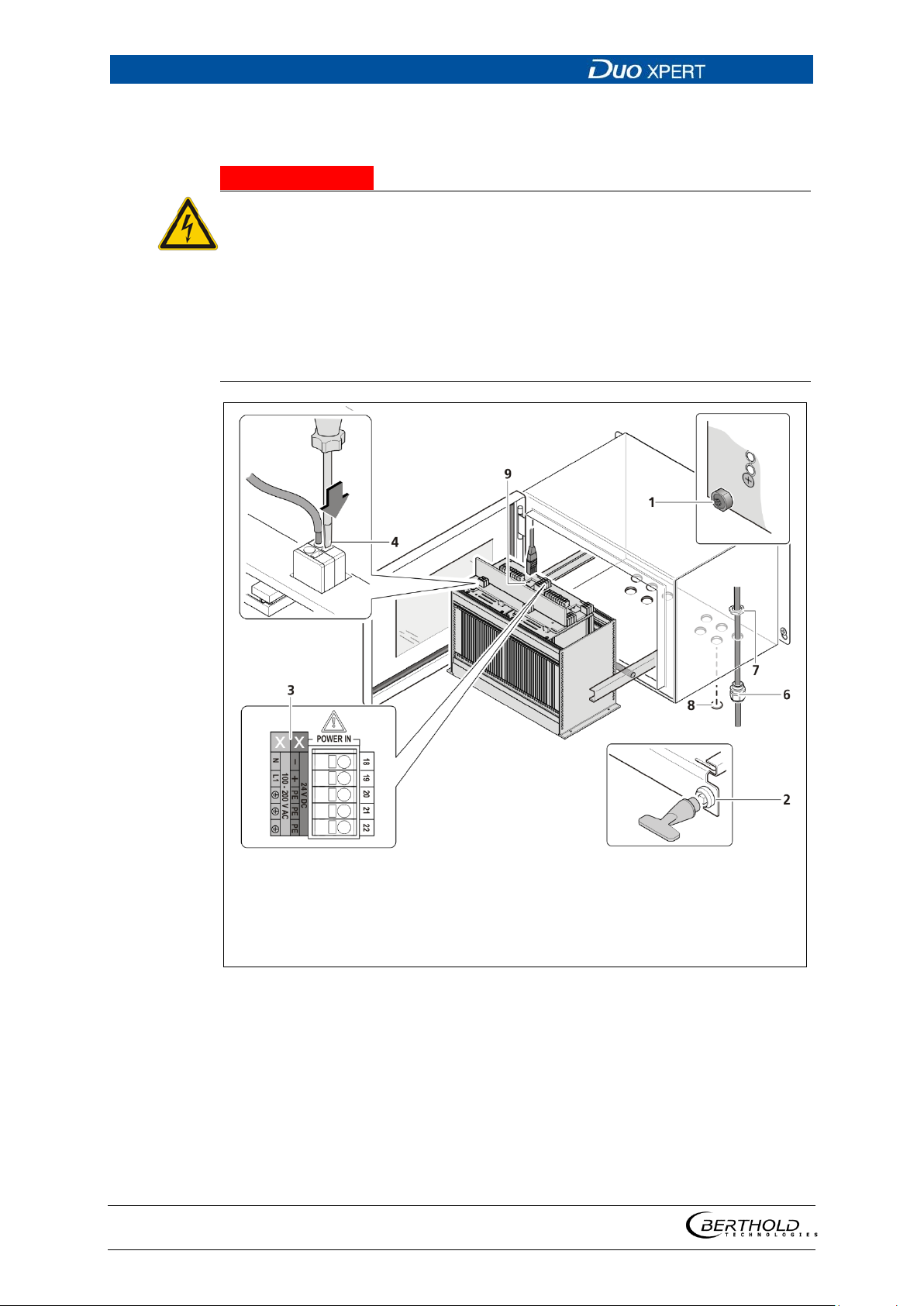
Fig.
5.2 Electric connection in the wall housing
The installation may only be carried out by a qualified electrician.
Please adhere to the relevant safety regulations.
Installation/maintenance may only be carried out if the device has been de-
energised.
Only open the device when free of voltage.
In case of an electric shock, carry out first aid measures and immediately call an
emergency service.
20 Electrical connection in the wall housing (Ex.: master-master)
1. Make sure that the locking bolts (Fig. 20, item 1) of all modules are tight-
ened in order to prevent slipping.
2. Loosen the lock (Fig. 20, item 2) using the supplied square key and pull the
subrack out.
3. Fold the subrack downward cautiously.
4. Run the cables through the cable glands (Fig. 20, item 6) through the open-
ings of the wall housing and through the counternut cable glands (Fig. 20,
56925BA2 Rev. 03, 11/2017
item 7).
Page 43
LB 470 Level 5 Electric Installation
43
NOTICE
NOTICE
NOTICE
NOTICE
Tip
5. Screw the the cable glands (Fig. 20, item 6) with the counternut cable glands
(Fig. 20, item 7).
Apply the voltage of the specified and marked (Fig. 20, item 3) range only!
Note the specification relating to Cables, Protective earth, equipotential bonding and EIA-485 (RS-485) in chapter 5.1.
6. Connect the lines according to assignment (chap.5.4 or chap.5.5) to the ter-
minal board (Fig. 20, item 3).
7. Open the terminal connection (Fig. 20, item 4) with an operating tool (slot-
ted screwdriver) and insert the stripped wire (min. 8 mm) (Fig. 20,item 5). The
terminal connection closes by pulling out the operating tool.
The terminal connections are designed for wires (flexible) with a conductor
cross-section from 0.2 mm² to 2.5 mm² (with ferrule without plastic sleeve) or
0.2 mm² to 1.5 mm² (with ferrule with plastic sleeve). AWG = 24 – 12.
8. Plug the network plug into the RJ45 socket (Fig. 20, item 9) (optional).
9. Tighten all cable glands (Fig. 20, item 6) to ensure optimal sealing and ten-
sion relief until the gasket insert closes between screw down nut and cable.
10. Check tension relief of all cable glands by pulling the cables smoothly.
The cables must not move. If necessary tighten the cap nuts of the cable
glands.
11. Slide the subrack into the wall housing and lock it with the square wrench.
The wall enclosure is supplied with blanking elements in all cable glands. It
must be ensured that there are blanking elements in all unused cable glands.
Otherwise, the IP protection is not given.
Only use cable that is suitable for connection to the corresponding terminals
may be used. Detailed specifications can be found in the chapter 5.1.2 Cables
and Lines.
The master/slave connections of the installed devices are already manufactured above the circuit board in the wall housing. If additional slave modules
(e.g. from other wall housings) are connected, the terminals appropriate for
use on the terminal board should be used.
56925BA2 Rev. 03, 11/2017
Page 44
5 Electric Installation LB 470 Level
44
j DANGER
Danger to life from electric shock!
master / master
master / 3x slave
NOTICE
NOTICE
5.3 Electrical connection in a 19" subrack with terminal
board
The installation may only be carried out by a qualified electrician.
Please adhere to the relevant safety regulations.
Installation/maintenance may only be carried out if the device has been
de-energised.
Only open the device when free of voltage.
In case of an electric shock, carry out first aid measures and immediately call an
emergency service.
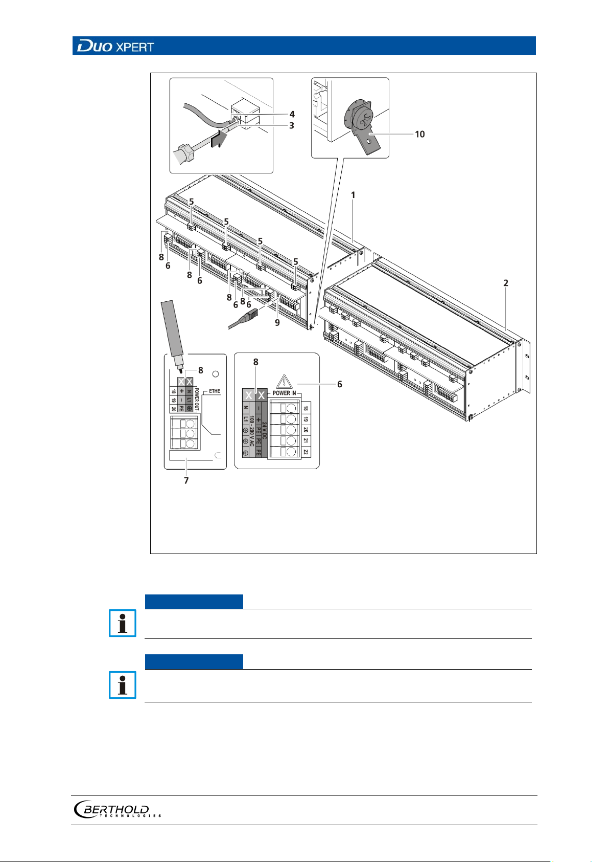
The terminal board master/slave is used twice (Fig. 21, item 2) for the variant to
install 2 master EVUs and 6 slave modules.
The terminal board master/master (Fig. 21, item 1) is used twice for the variant to
install 4 master EVUs.
CHANNEL A CHANNEL A
CHANNEL B CHANNEL B
CHANNEL C
CHANNEL D
The 19" subrack must be accessible from the rear for the electrical installation.
Prior to initial start-up, the voltage range (Fig. 21, item 8) must be marked
with chemical resistance on all input and output terminals!
56925BA2 Rev. 03, 11/2017
Page 45
LB 470 Level 5 Electric Installation
45
1
2
3
4
5
Variant master/master
Variant master/ 3x slave
Opening terminal connection
Stripped wire
Connection detector
6
7
8
9
10
Supply Voltage
Voltage output
Marking Supply Voltage
RJ45 connector (network)
PE connection
Fig.
NOTICE
NOTICE
21 Electrical connection in the 19" subrack
Apply the voltage of the specified and marked (Fig. 20, item 3) range only!
Note the specification relating to Cables, Protective earth, equipotential bonding and EIA-485 (RS-485) in chapter 5.1.
1. Unused slots must be closed with blinds.
2. Label the voltage range permanently and chemically (Fig. 21, item 8).
3. Connect the lines according to assignment (chap.5.4 or chap.5.5) to the ter-
minal board.
56925BA2 Rev. 03, 11/2017
Page 46
5 Electric Installation LB 470 Level
46
NOTICE
NOTICE
4. Open the terminal connection (Fig. 21, item 3) with an operating tool (slot-
ted screwdriver) and insert the stripped wire (min. 8 mm) (Fig. 21,item 4). The
terminal connection closes by pulling out the operating tool.
5. The terminal connections are designed for wires (flexible) with a conductor
cross-section from 0.2 mm² to 2.5 mm² (with ferrule without plastic sleeve) or
0.2 mm² to 1.5 mm² (with ferrule with plastic sleeve). AWG = 24 – 12.
6. Plug the network plug into the RJ45 socket (Fig. 21, item 9) (optional).
7. Check the correct connection of the PE conductor (Fig. 21, item 10).
Note the specification relating to Protective earth and equipotential bonding
in chapter 5.1.4.
Only cable that is suitable for connection to the corresponding terminals may
be used. Detailed specifications can be found in the chapter 5.1.2 Cables and
Lines.
56925BA2 Rev. 03, 11/2017
Page 47
LB 470 Level 5 Electric Installation
47
Fig.
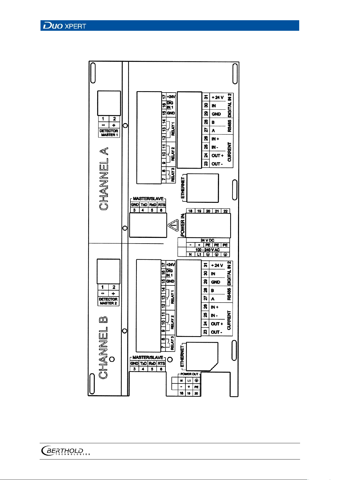
5.4 Terminal board master/master
22 Terminal board master/master back side (Label A/B)
56925BA2 Rev. 03, 11/2017
Page 48
5 Electric Installation LB 470 Level
48
NOTICE
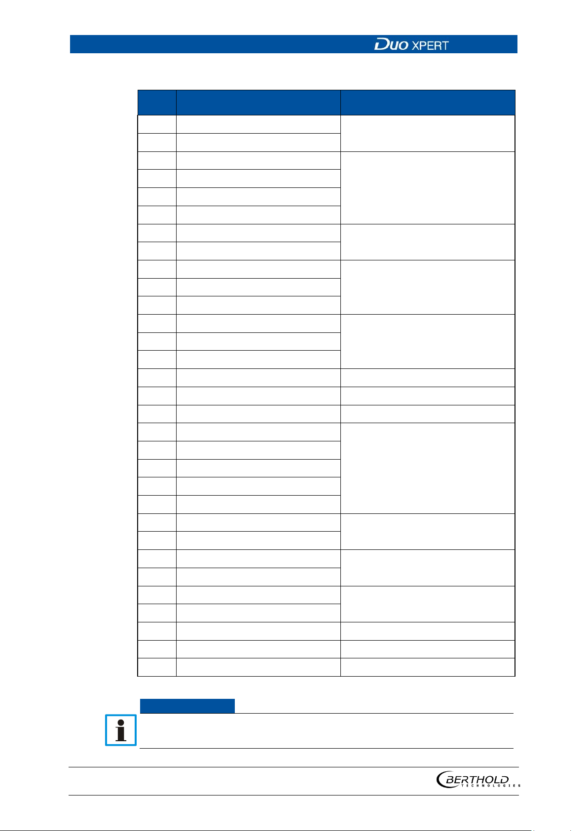
Item
Plug connectors
Function
Pin assignment master/master
1 DETECTOR MASTER –
2 DETECTOR MASTER +
3 MASTER/SLAVE GND
4 MASTER/SLAVE TxD
5 MASTER/SLAVE RxD
6 MASTER/SLAVE RTS
7 RELAIS 3 NC
8 RELAIS 3 COM
9 RELAIS 2 NC
10 RELAIS 2 NO
11 RELAIS 2 COM
12 RELAIS 1 NC
13 RELAIS 1 NO
14 RELAIS 1 COM
15 DIGITAL IN 1 GND GND
16 DIGITAL IN 1 IN Logic Input
17 + 24 V OUT 24 V out (max. 200 mA)
18 POWER DC 24 V – / AC N
19 POWER DC 24 V + / AC L1
Connection LB 4700 or LB 44xx
detector
Connection of further slave units
DIGITAL OUT
DIGITAL OUT
Error DIGITAL OUT
20 PE
21 PE
22 PE
23 CURRENT OUT –
24 CURRENT OUT +
25 CURRENT IN –
26 CURRENT IN +
27 RS 485 A
28 RS 485 B
29 DIGITAL IN 2 GND GND
30 DIGITAL IN 2 IN Logic Input
31 + 24 V OUT 24 V out (max. 200 mA)
The connections master A, B, C, D are identical.
24 V DC / 100-240 V AC
4 mA … 20 mA
Not used at LB 470
Communication and service interface (master-master)
56925BA2 Rev. 03, 11/2017
Page 49
LB 470 Level 5 Electric Installation
49
Fig.
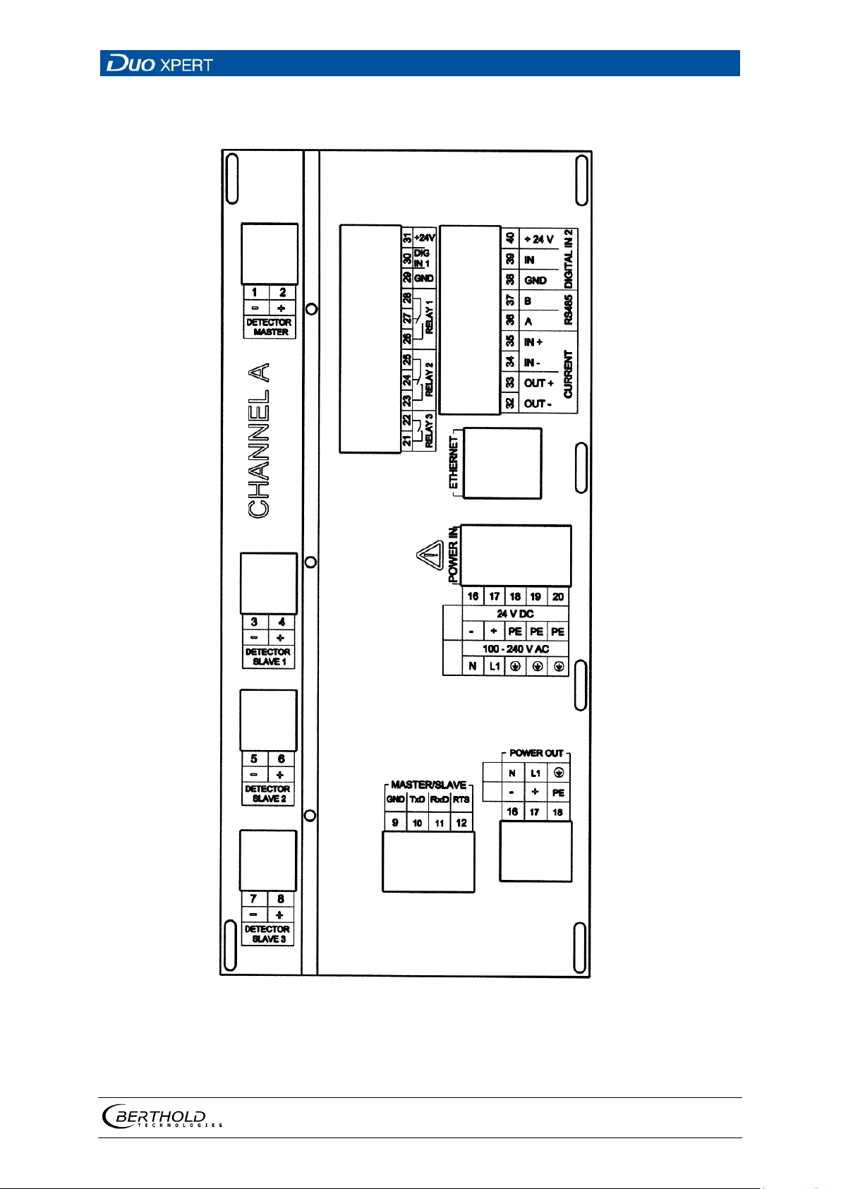
5.5 Terminal board master/slave
23 Terminal board master/slave back side (label A)
56925BA2 Rev. 03, 11/2017
Page 50
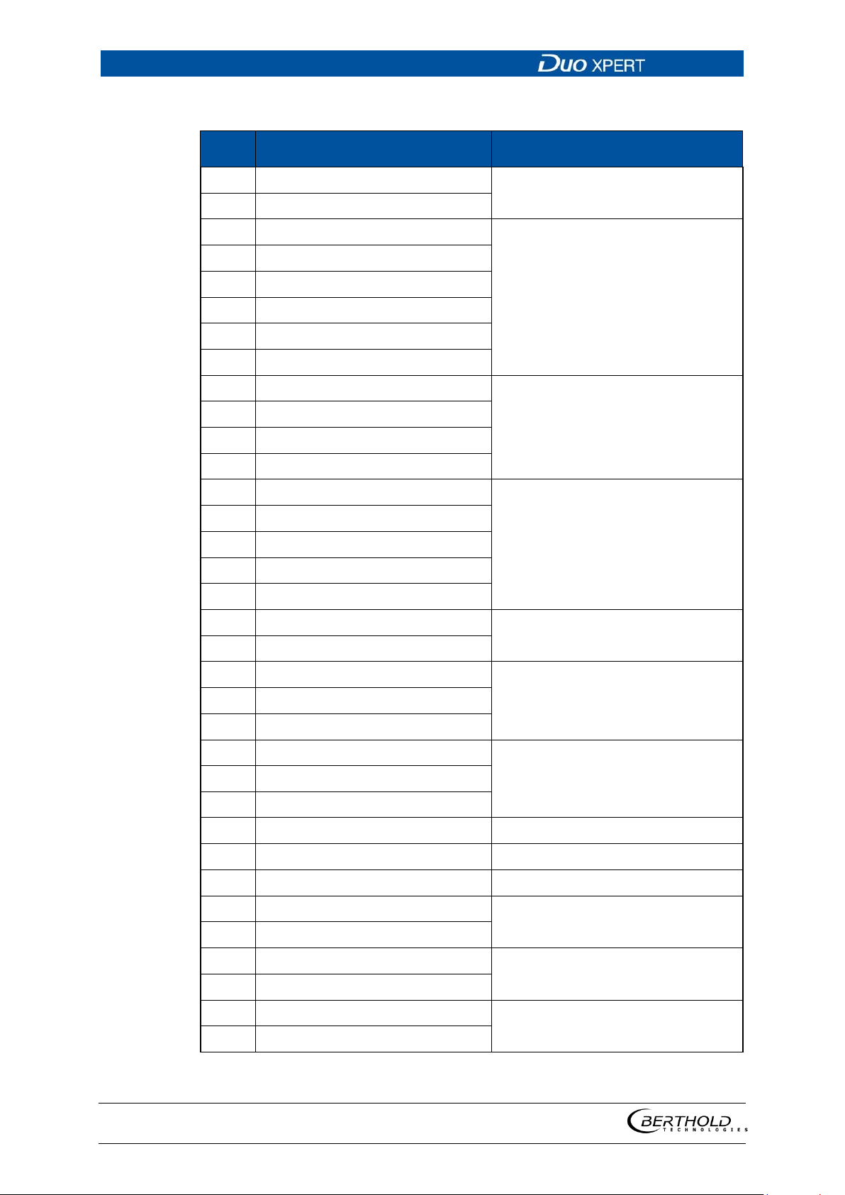
5 Electric Installation LB 470 Level
50
item
Plug connectors
Function
Pin assignment master/slave
1 DETECTOR MASTER –
2 DETECTOR MASTER +
3 DETECTOR SLAVE 1 –
4 DETECTOR SLAVE 1 +
5 DETECTOR SLAVE 2 –
6 DETECTOR SLAVE 2 +
7 DETECTOR SLAVE 3 –
8 DETECTOR SLAVE 3 +
9 MASTER/SLAVE GND
10 MASTER/SLAVE TxD
11 MASTER/SLAVE RxD
12 MASTER/SLAVE RTS
16 POWER DC 24 V – / AC N
17 POWER DC 24 V + / AC L1
18 PE
19 PE
Connection LB 4700 or LB 44xx
detector
Connection of further slave units
Connection of further slave units
24 V DC / 100-240 V AC
20 PE
21 RELAIS 3 NC
DIGITAL OUT
22 RELAIS 3 COM
23 RELAIS 2 NC
24 RELAIS 2 NO
DIGITAL OUT
25 RELAIS 2 COM
26 RELAIS 1 NC
27 RELAIS 1 NO
Error DIGITAL OUT
28 RELAIS 1 COM
29 DIGITAL IN 1 GND GND
30 DIGITAL IN 1 IN Logic Input
31 + 24 V OUT 24 V out (max. 200 mA)
32 CURRENT OUT –
4 mA … 20 mA
33 CURRENT OUT +
34 CURRENT IN –
Not used at LB 470
35 CURRENT IN +
36 RS 485 A
37 RS 485 B
Communication and service interface (master-master)
56925BA2 Rev. 03, 11/2017
Page 51
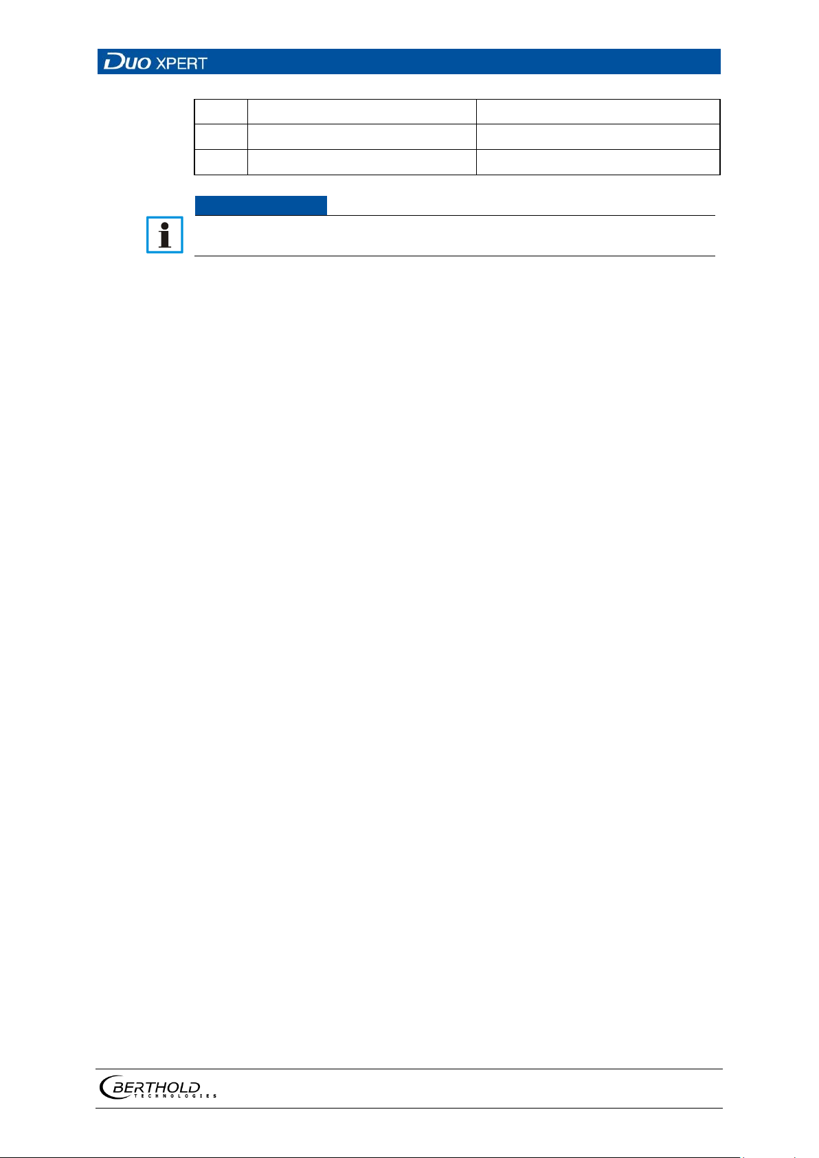
LB 470 Level 5 Electric Installation
51
NOTICE
38 DIGITAL IN 2 GND GND
39 DIGITAL IN 2 IN Logic Input
40 + 24 V OUT 24 V out (max. 200 mA)
The connections master/slave A and master/slave B are identical.
56925BA2 Rev. 03, 11/2017
Page 52
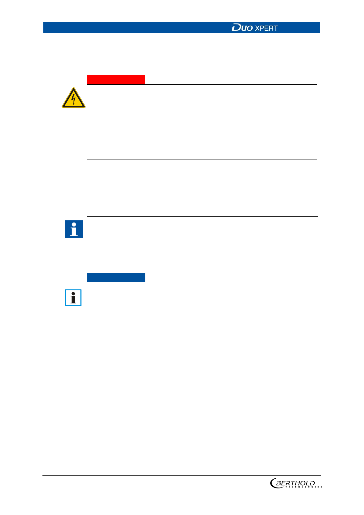
5 Electric Installation LB 470 Level
52
j DANGER
Danger to life from electric shock!
IMPORTANT
NOTICE
5.6 Electrical connection in the 19″ subrack with clamp
block
The installation may only be carried out by a qualified electrician.
Please adhere to the relevant safety regulations.
Installation/maintenance may only be carried out if the device has been
de-energised.
Only open the device when free of voltage.
In case of an electric shock, carry out first aid measures and immediately call an
emergency service.
If the units are installed in the 19" subrack without terminal board, the electrical
connections are made via clamp blocks. These clamp blocks are already installed in
the 19" subracks and are also available as an optional accessory.
In the case of applications with clamp blocks a contact protection must be provided by the customer when voltage is applied. The cable connections of
clamp blocks have to be in accordance with IEC 61010-1 (2010).
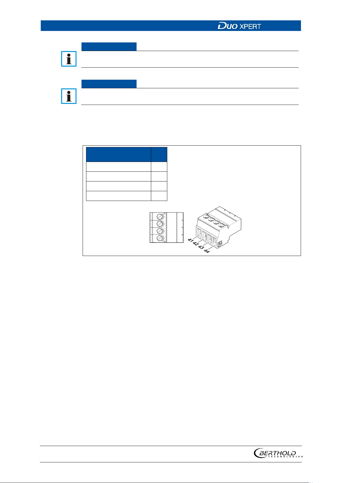
The connection between the master EVU and slave modules is made with a 4-pin
master/slave plug (see chap. 5.6.1).
The LB 470 is restricted pin-compatible with the terminals of the LB 440. The
pins for the power supply, the probe interface and the current output are at
the same position. If only those ports are used, then a LB 440 can be replaced
by a LB 470 without re-wiring.
56925BA2 Rev. 03, 11/2017
Page 53
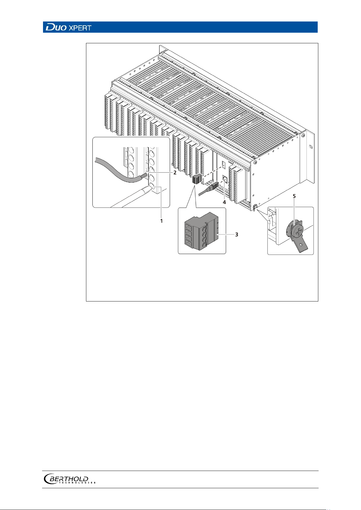
LB 470 Level 5 Electric Installation
53
1
2
3
Clamping screw (M2.5)
Opening terminal connection
4-pin master/slave plug (only master EVU)
terminals 41-44
4 5 RJ45 connector (network)
PE connection
Fig.
24 Electrical connection in the 19″ component rack (Ex.: 1xMaster,
9xSlave)
1. Connect the lines to the clamp blocks according to assignment (chap. 5.6.2 or
5.6.3).
2. Open the clamping screw (Fig. 24, item 1) and insert the stripped wire (min. 8
mm).
The terminal connections are designed for wires with a conductor cross-sec-
tion from 0.2 mm² to 2.5 mm².
3. Screw the clamping screws with a tightening torque of 0.4 - 0.5 Nm.
4. Plug in the master/slave plug and reconnect the lines in accordance with as-
signment (chap. 5.6.1 and chap. 5.6.2 or chap. 5.6.3).
5. Plug the network plug into the RJ45 socket (Fig. 24, item 4) (optional).
6. Check the correct connection of the PE conductor (Fig. 24, item 5).
56925BA2 Rev. 03, 11/2017
Page 54
5 Electric Installation LB 470 Level
54
NOTICE
NOTICE
Signal
Pin
Fig.
Note the specification relating to Protective earth and equipotential bonding
in chapter 5.1.4.
Only cable that is suitable for connection to the corresponding terminals may
be used. For further specifications, see appendix “Technical Information”.
5.6.1 84BAssignment terminals master/slave plug
TxD 41
RxD 42
RTS 43
GND 44
25 Assignment Terminals master/slave plug
56925BA2 Rev. 03, 11/2017
Page 55
LB 470 Level 5 Electric Installation
55
Pin
Signal
Signal
Pin
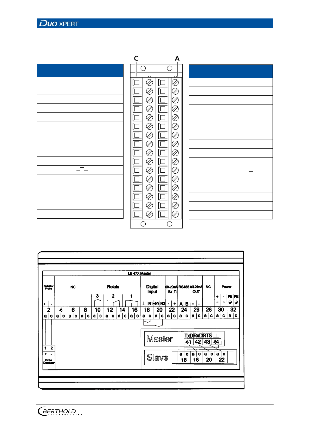
5.6.2 85BAssignment clamp block master EVU
DETECTOR GND C - 2
not assigned C - 4
not assigned C - 6
not assigned C - 8
RELAY 3 COM C - 10
RELAY 2 COM C - 12
RELAY 1 NC C - 14
RELAY 1 COM C - 16
DIGITAL IN 1 C - 18
DIGITAL IN 2 C - 20
CURRENT IN + ( )
RS 485 B C - 24
CURRENT OUT – C - 26
not assigned C - 28
100-240 V AC, 24 V DC – C - 30
Protective conductor PE C - 32
C - 22
A - 2 DETECTOR +
A - 4 not assigned
A - 6 not assigned
A - 8
A - 10 RELAY 3 NO
A - 12 RELAY 2 NO
A - 14 RELAY 2 NC
A - 16 RELAY 1 NO
A - 18 DIGITAL IN GND
A - 20 + 24 V
A - 22
A - 24 RS 485 A
A - 26 CURRENT OUT +
A - 28 not assigned
A - 30 100-240 V AC, 24 V DC +
A - 32 Protective conductor PE
not assigned
CURRENT IN – ( )
Fig. 26 Assignment clamp block master EVU
Fig. 27 Terminal assignment master EVU (display on the module)
56925BA2 Rev. 03, 11/2017
Page 56
5 Electric Installation LB 470 Level
56
Pin
Signal
Signal
Pin
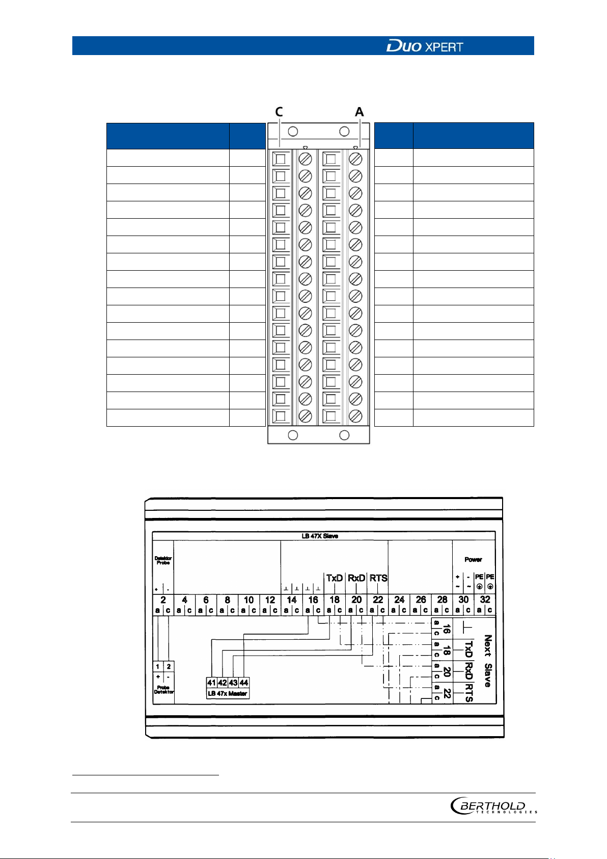
5.6.3 86BAssignment clamp block slave module
DETECTOR SLAVE GND C - 2
not assigned C - 4
not assigned C - 6
not assigned C - 8
not assigned C - 10
not assigned C - 12
GND C - 14
GND C - 16
RTS to the SLAVE C - 18
RxD to the SLAVE C - 20
TxD to the SLAVE C - 22
not assigned C - 24
not assigned C - 26
not assigned C - 28
Main AC, DC 24 V – C - 30
Protective conductor PE C - 32
A - 2 DETECT. SLAVE +15 V
A - 4 not assigned
A - 6 not assigned
A - 8
A - 10 not assigned
A - 12 not assigned
A - 14 GND
A - 16 GND
A - 18
A - 20
A - 22
A - 24 not assigned
A - 26 not assigned
A - 28 not assigned
A - 30 Main AC, DC 24 V +
A - 32 Protective conductor PE
not assigned
RTS to MASTER/SLAVE
RxD to the MASTER/SLAVE
TxD to the MASTER/SLAVE
1
0F
Fig. 28 Assignment clamp block slave module
Fig.29 Terminal assignment (display on slave module)
1
optional
56925BA2 Rev. 03, 11/2017
Page 57
LB 470 Level 6 Operation of the Software
57
Fig.
Fig.
IMPORTANT
6 Operation of the Software
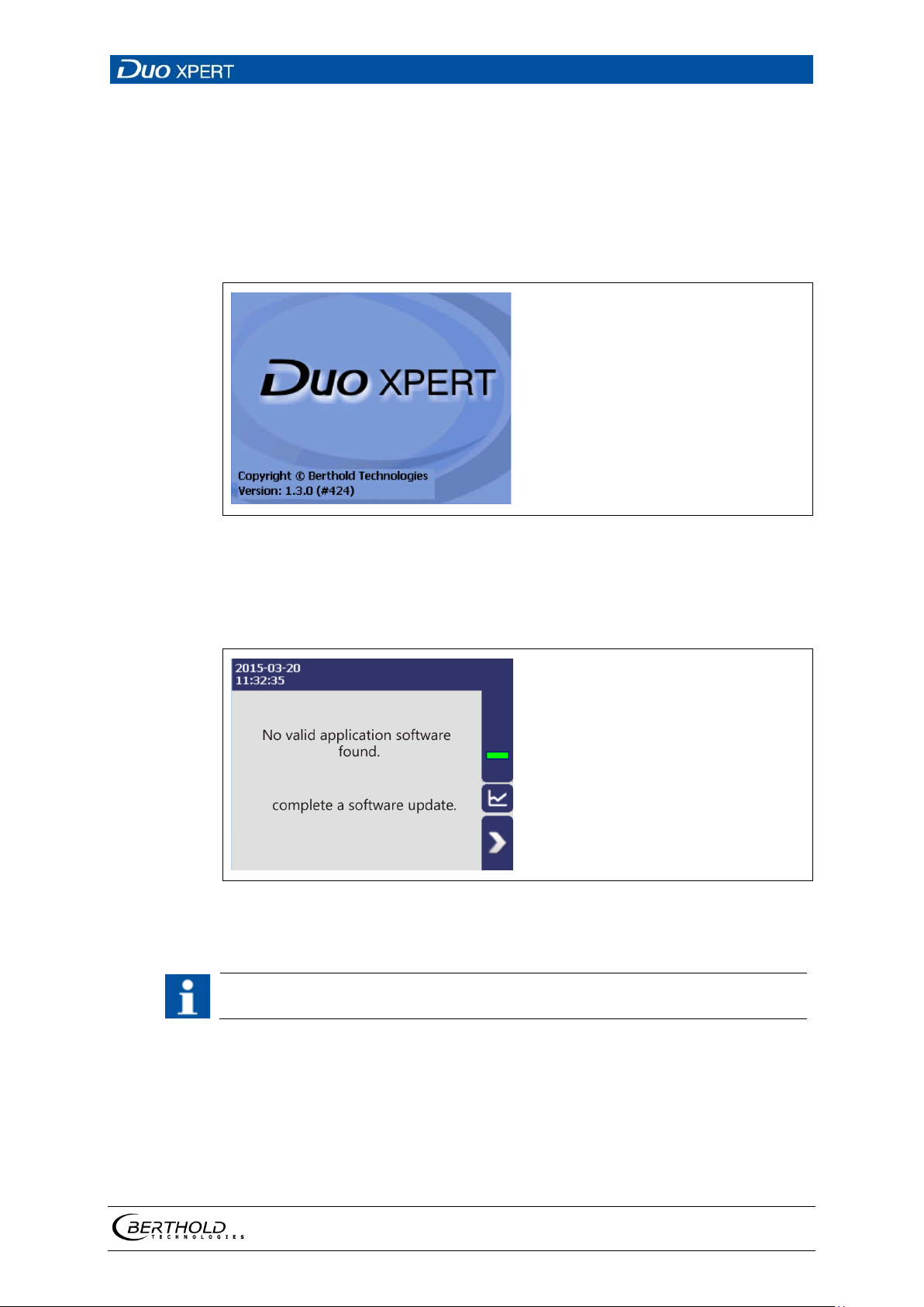
6.1 System start
30 Start screen with display of the software version
System start with invalid application software
A different menu structure is present in this mode.
31 Start screen (Invalid application software)
The communication between the sensor and EVU is limited to 1200 baud. Accordingly, there is a load time for data that are retrieved in the detector.
56925BA2 Rev. 03, 11/2017
Page 58
6 Operation of the Software LB 470 Level
58
IMPORTANT
1
2
3
4
5
6
7
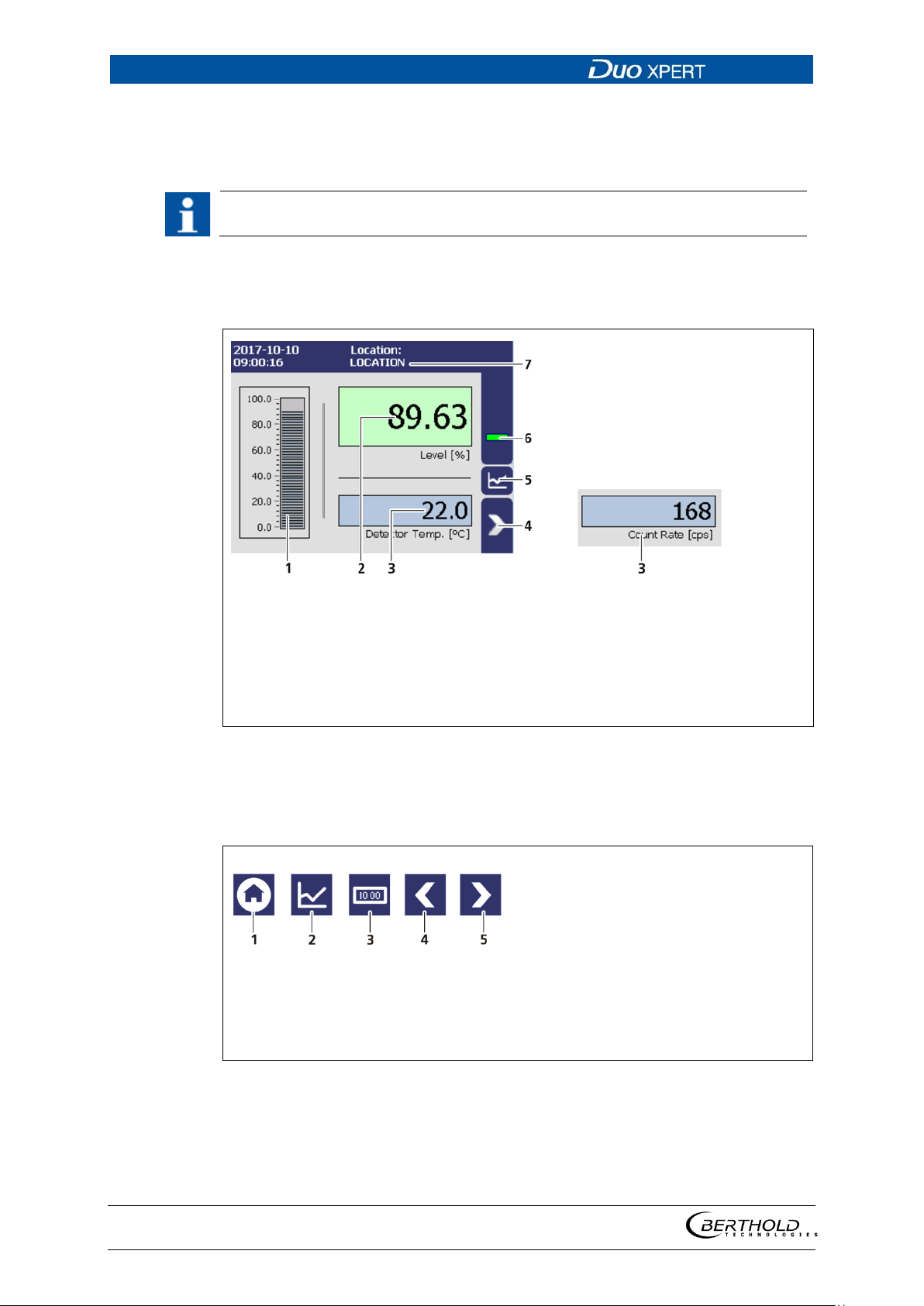
level scale [%]
level display [%]
Detector temperature / Count rate [cps]
Menu
Diagram display
Status information
Location of the measuring point
Fig.
1
2
3
4
5
Home (standard display)
Diagram display
One menu level back
One menu level forward
Fig.
6.2 EVU standard display
Changing the language of the user interface is described in chapter 7.3.1 Systen | Interface.
Click on the blue field in order to switch the display between detector temperature
(Fig. 32, item 3) and count rate (Fig. 32, item 3). The designation of the measuring
point (Fig. 32, item 7) can be changed in Chapter 7.1.1.
32 Standard display of the EVU
6.3 Navigation
Data
33 Icons for navigation
56925BA2 Rev. 03, 11/2017
Page 59
LB 470 Level 6 Operation of the Software
59
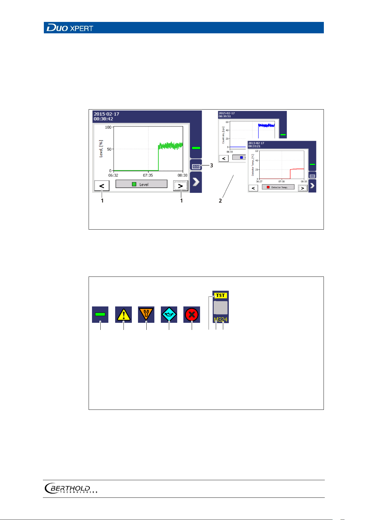
1
2
3
Arrow keys
Diagrams
Standard display
Fig.
1
2
3
4
5
6
7
8
No event
Outside of specification
Function check
Maintenance required
Failure (error)
Information test (simulation)
Character D (detector) or M (measuring unit)
Event code
Fig.
86
1
2 3
4
5
7
6.3.1 Diagram display
Clicking the diagram symbol (Fig. 32, item 5) changes the view to the diagram display. The arrow keys (Fig. 34, item 1) are used to switch between the diagrams
Level– Count Rate – Detector Temperature.
Clicking the display symbol (Fig. 34, item 3) changes the view to the standard display.
34 Diagram display of the EVU
6.4 Status messages
35 Status information
56925BA2 Rev. 03, 11/2017
Page 60
6 Operation of the Software LB 470 Level
60
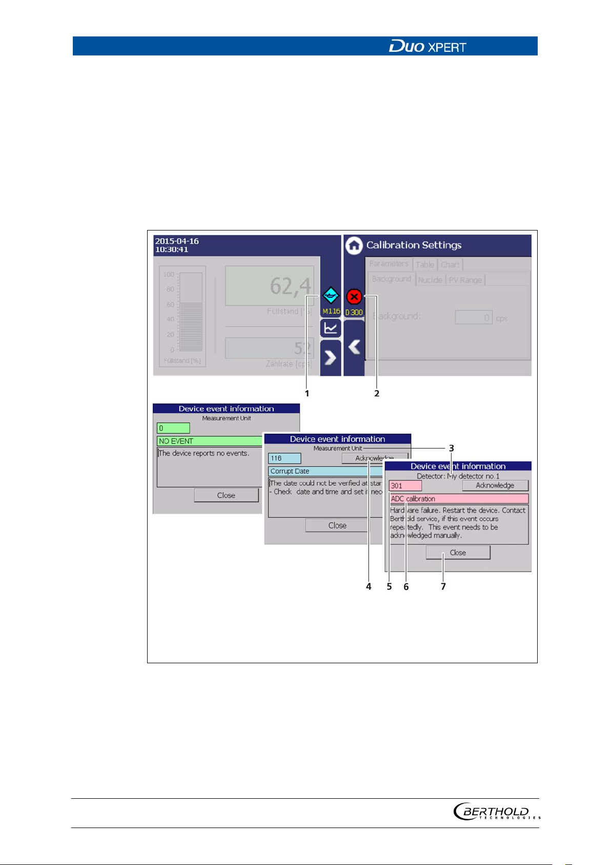
1
2
3
4
Event reporting in the standard display
Event message in the menu structure
Device concerned (detector / measuring in-
strument)
Button <Confirm>
5
6
7
Error number
Title of event report
Button <Close>
Fig.
6.4.1 87BEvent reports
Events are displayed in the standard display and in the submenus as a symbol. All
events are displayed on the main screen. A specific “D” (for detector) indicates that
a detector has an event, the prefix “M” (for measuring unit) indicates that there is
an event in the LB 470 transmitter. In the event of a detector fault, the operating
manual of the detector must be observed.
Only the event with the highest priority will be displayed. Refer to the menus Transmitter Events (chapter 8) and Detector Event Log "Detector-Service" (chapter 7.3.2)
for additional information.
36 Event reports
1. Click on the icon (Fig. 36, item 1, item 2) to display detailed information
about the event.
2. Click the button <Acknowledge> to confirm an event that requires a manual
confirmation.
The event description indicates the next event or reports no further events.
56925BA2 Rev. 03, 11/2017
Page 61
LB 470 Level 6 Operation of the Software
61
IMPORTANT
NOTICE
1
2
3
4
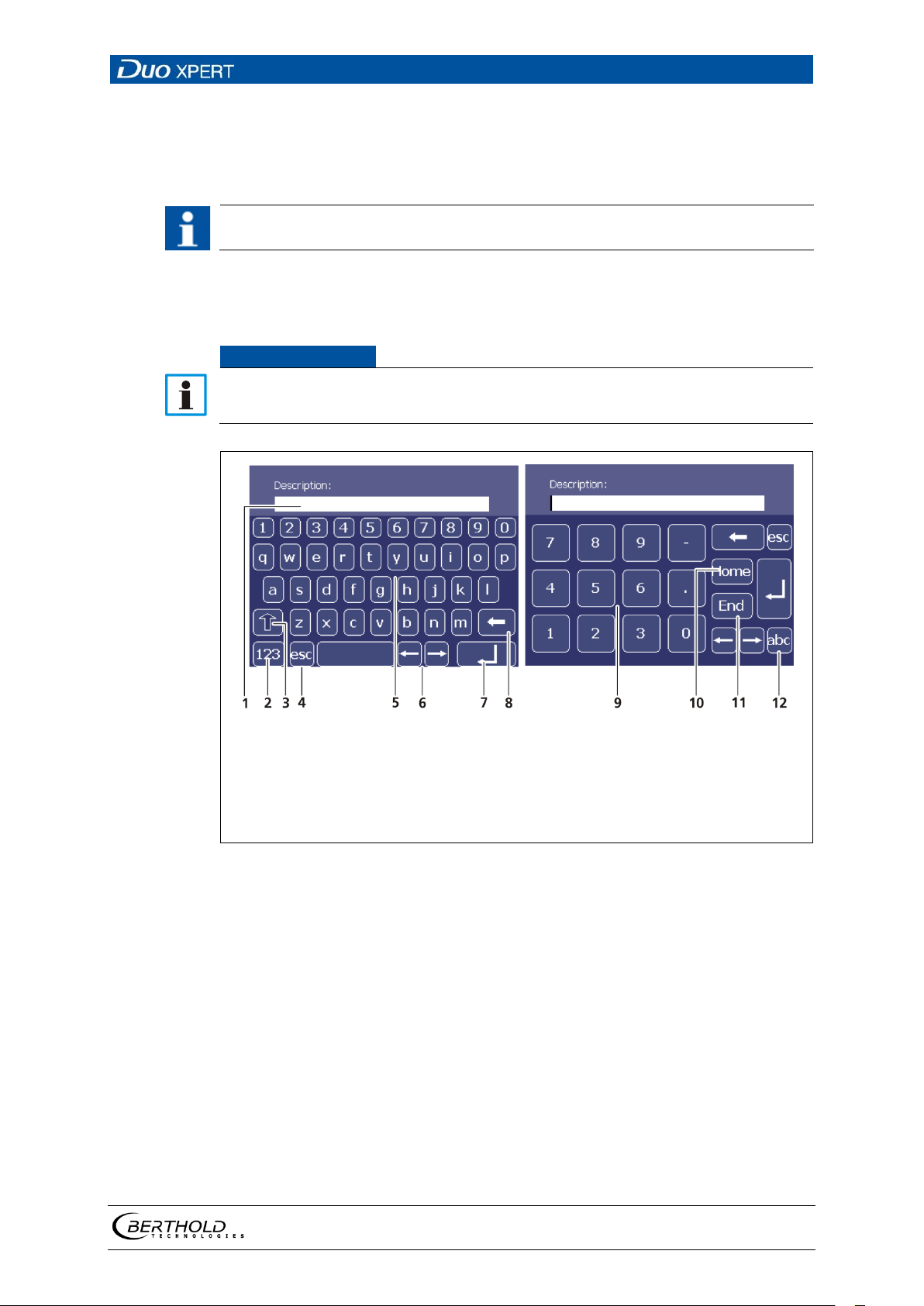
5
6
Input line
Shift key for numbers
Shift to upper case characters
Escape key
Keypad
Navigation buttons
7
8
9
10
11
12
Input key
Delete key
Number field
Home (item1) key
End key
Shift key for letters
Fig.
3. Click <Close> to return to the submenu or to the standard display.
The icon disappears from the status information.
If you click the button <Close>, the event message is closed, the icon continues
to be displayed.
6.5 Input field
The input field appears by clicking on the blue display panels.
37 Screen keyboard
56925BA2 Rev. 03, 11/2017
Page 62
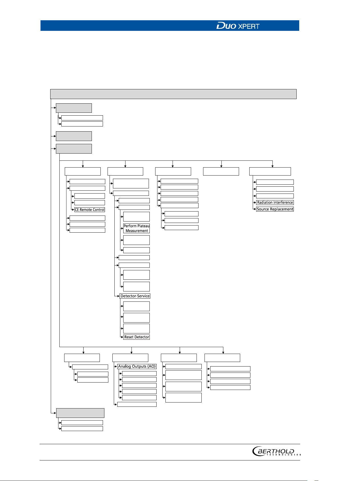
7 Main Menu Device Setup LB 470 Level
62
Main Menu - Device Setup
Identfification
Access
Setup
System
Sensors
Calibration
Measurement
Signal-Condition
Inputs Outputs Alarms Simulation
Backup / Restore
Detector
Configuration
[DETECTOR]
Overview
Calibrate
Recall
Calibration Settings
Location
Device Information
Plateau
Temperature
Plateau
Settings
Plateau
Table
Plateau curve
High Voltage
Detector
Type
HV
Settings
Device
Information
Event-Log
Event
Overview
PV Range
Network
Damping
Date / Time
Interfaces
Units
Rapid Switch
Reset Device
DI State
DI-Assignment
AO-Monitoring
AO-Mapping
AO Failure Mode
Calibration
PVAlarm Function
PV Alarm
Settings
Alarm Function
Settings
Digital Outputs (DO)
Analog Output (AO)
Count Rate
PV
Local Display
Language
Backup
Restore
Chap. 7.2
Chap. 7.3
Chap. 7.1
Adjust
GPC
GPCCalibration
GPCSettings
GPC reset
Chap. 7.4
AO Limits
AO
DigitalOutput (DO)
Det.-Temp
Det.-Temp. Alarm
DigitalInputs (DI)
7 Main Menu Device Setup
56925BA2 Rev. 03, 11/2017
Page 63
LB 470 Level 7 Main Menu Device Setup
63
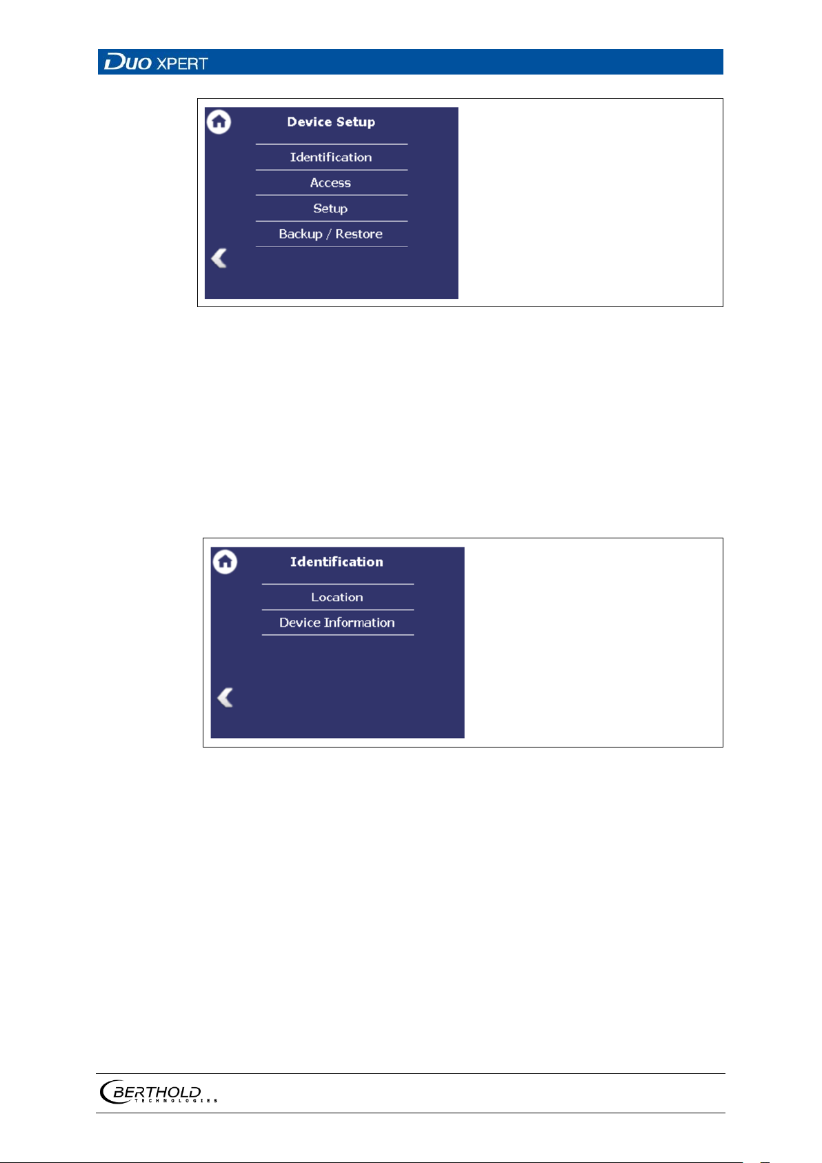
Fig.
Fig.
38 Menu "Device Setup"
7.1 Menu identification
Device Setup | Identification
You can make the following settings and read information in the Identification
menu:
• Display and change the location name
• Display of hardware and software information
39 Menu "Identification"
56925BA2 Rev. 03, 11/2017
Page 64
7 Main Menu Device Setup LB 470 Level
64
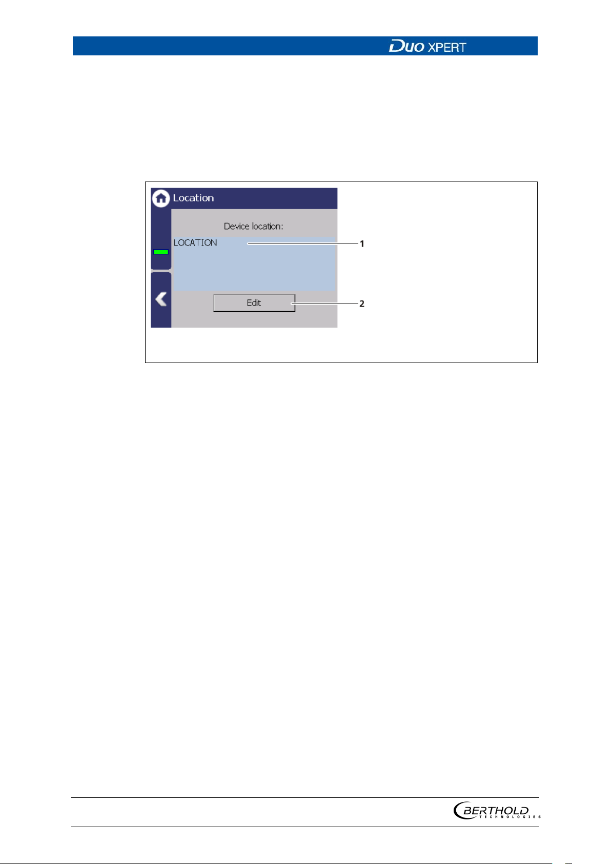
1 2 Name Device location
Button <Edit>
Fig.
7.1.1 88BLocation
Device Setup | Identification | Location
The location of the evaluation unit is displayed (Fig. 39, item 1) in the Location
menu. The name can only be edited (7.2 Menu Access) in the access level "Standard". The Location is displayed on the EVU standard display (Fig. 32, item 8).
40 Device location
1. Click <Edit> (Fig. 39, item 2) to open the input field.
2. Enter a location name for the evaluation unit.
3. Confirm with the Enter key.
The name has been changed.
56925BA2 Rev. 03, 11/2017
Page 65
LB 470 Level 7 Main Menu Device Setup
65
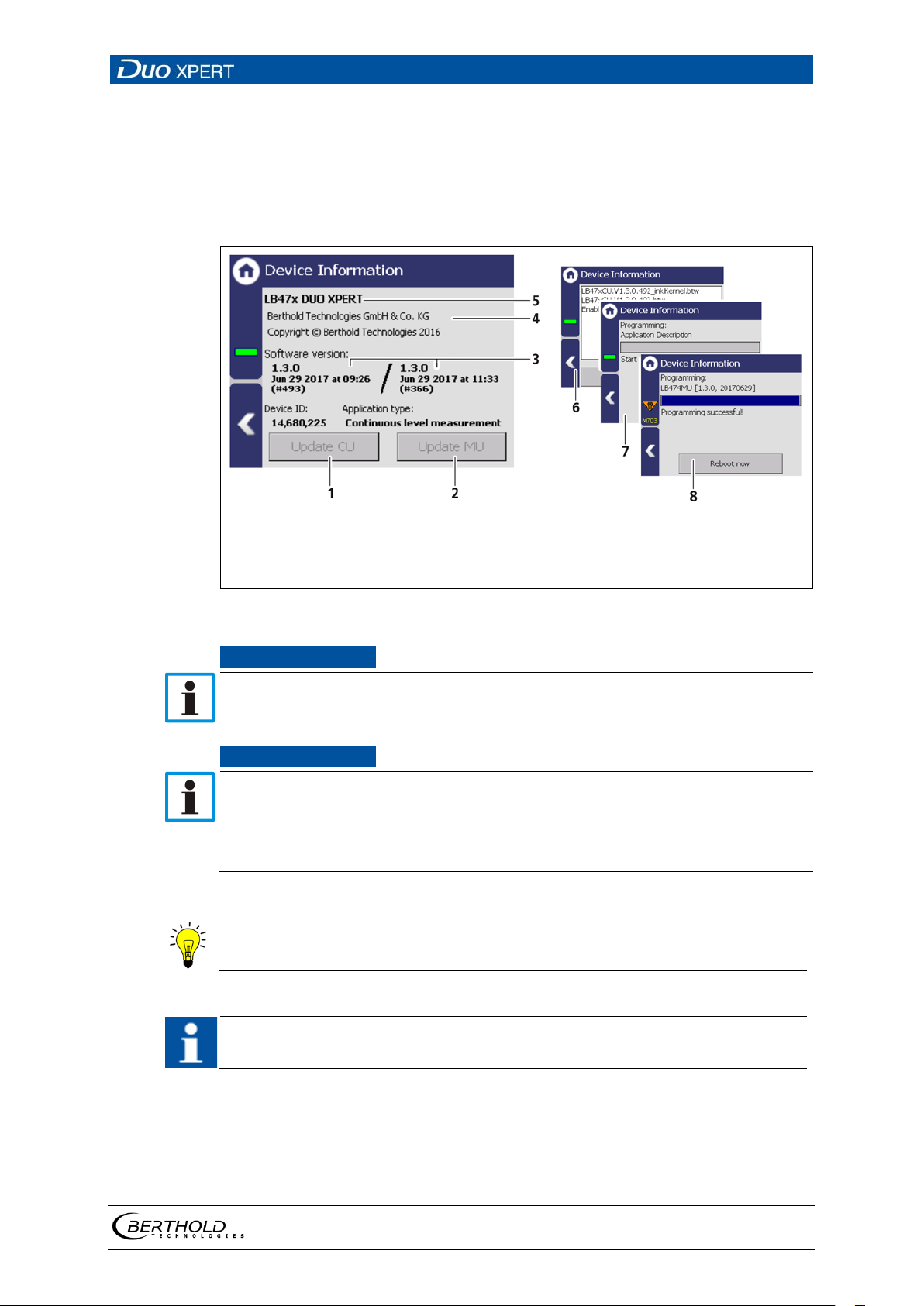
1
2
3
4
CU update (Control Unit)
MU update (Measurement Unit)
Software versions
Manufacturer
5
6
7
8
Device Information
Selection window update file
Process window
Result window
Fig.
NOTICE
NOTICE
Settings are deleted!
update.
Tip
IMPORTANT
7.1.2 89BDevice information
Device Setup | Identification | Device information
Information about hardware and software of the evaluation unit are displayed In
the submenu "Device information".
41 Device information
During an update where the first or second digit of the version changes, it is
necessary to reset the EVU to factory settings.
Carry out a backup of the measuring channel settings before resetting and
the update of the EVU (7.4.1 Backup).
The secured settings should then be imported after the successful software
The current software versions can be downloaded from the Berthold website
(www.berthold.com).
In order for the system to detect the update file it must not be located in an
index in the USB storage device.
Perform CU update
1. Save the current update file of the CU software on a USB storage device.
2. Connect a USB storage device to the device (Fig. 3, item 5).
3. The USB storage device is recognised by the system after a few seconds and
56925BA2 Rev. 03, 11/2017
Page 66
7 Main Menu Device Setup LB 470 Level
66
NOTICE
the <CU Update> (Fig. 40, item 1) button can be clicked.
4. Click on the button <CU Update> (Fig. 40, item 1).
The update is performed.
5. Measurement is interrupted.
6. Click the Button <Restart> to reboot the EVU.
Perform MU update
1. Save the current update file of the MU software on a USB storage device.
2. Connect a USB storage device to the device (Fig. 3, item 5).
3. The USB storage device is recognised by the system after a few seconds and
the <MU Update> (
4. Click on the button <MU Update> (Fig. 40, item 1).
The update is performed.
5. Measurement is interrupted.
6. Click the Button <Restart> to reboot the EVU.
Fig. 40, item 1) button can be clicked.
BERTHOLD TECHNOLOGIES recommends calibrating the current outputs whenever a module has been installed/replaced or if a software update has been
carried out.
56925BA2 Rev. 03, 11/2017
Page 67
LB 470 Level 7 Main Menu Device Setup
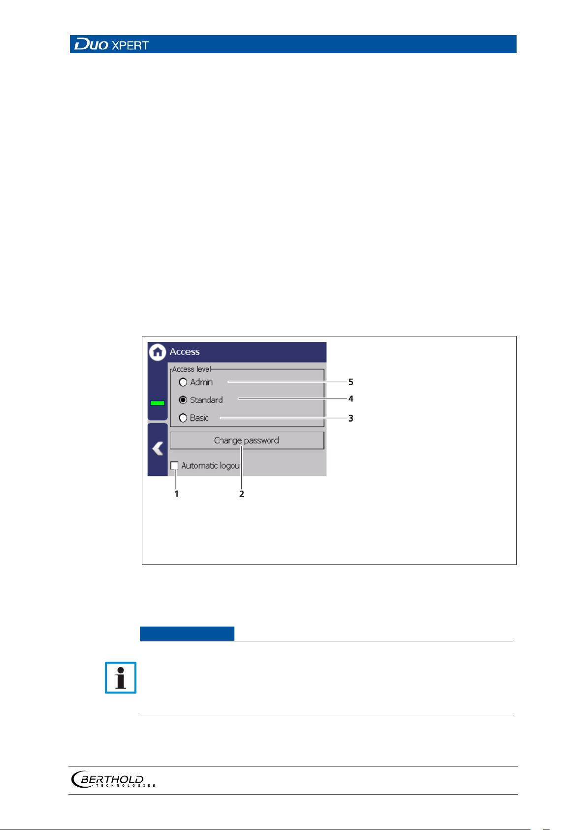
67
User Level Basic
You can see all important data but cannot make
User Level Standard
You can change all data necessary for operation
User Level Admin
This user level is only intended for the system
Automatic logout
Activating the selection box (Fig. 42 item 1) au-
1
2
3
4
5
Check box "Automatic logout"
Change <Change password>
User level "Basic"
User level "Standard"
User level "Admin"
Fig.
NOTICE
7.2 Menu Access
Device Setup | Access
You can set the user rights via the user levels and assign passwords in the submenu
Access. The system can be protected by a password against unauthorised changes.
The following user levels are available to you:
any changes.
(e.g. calibration).
management by BERTHOLD.
tomatically resets the access level Standard to
“Basic” when the system changes to the standard display after the timeout (chapter
7.3.1).
42 Access
Incorrect measurement and calibration parameters can be set through unauthorised inputs. These can possibly lead to production losses and damage in
the system.
Protect the measuring system from unauthorised entries with a password
and activate the function "Automatic logout".
56925BA2 Rev. 03, 11/2017
Page 68
7 Main Menu Device Setup LB 470 Level
68
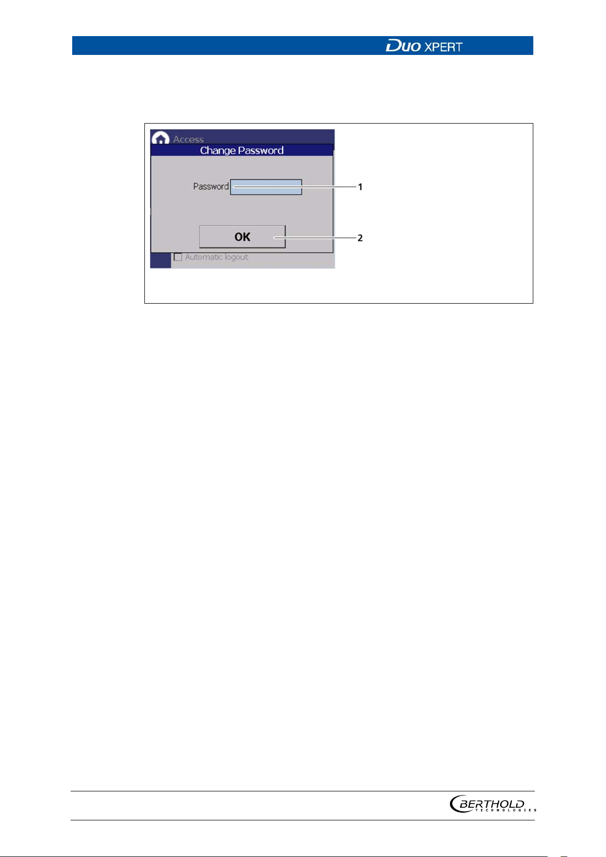
1 2 Text field
Button <OK>
Fig.
Assign / change password
To set or change a password, select "Standard" (Fig. 42, item 4) and click on
<Change password> (Fig. 42, item 2) to open the input field.
43 Change password
1. Click on the text field (Fig. 43, item 1.) to open the input field.
2. Enter a password (case-sensitive!).
3. Confirm with the Enter key.
4. Click <OK> (Fig. 43, item 2) to confirm.
The password has been set / changed.
56925BA2 Rev. 03, 11/2017
Page 69
LB 470 Level 7 Main Menu Device Setup
69
Fig.
Fig.
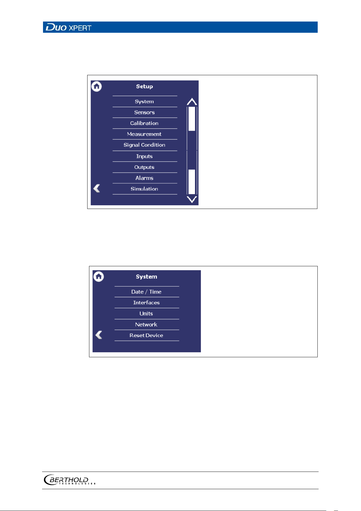
7.3 Menu Setup
Device Setup | Setup
44 Menu "Setup"
7.3.1 90BSystem (Date / Time, Interfaces, Units, Network, Reset)
Device Setup | Setup | System
45 Submenu "System"
56925BA2 Rev. 03, 11/2017
Page 70
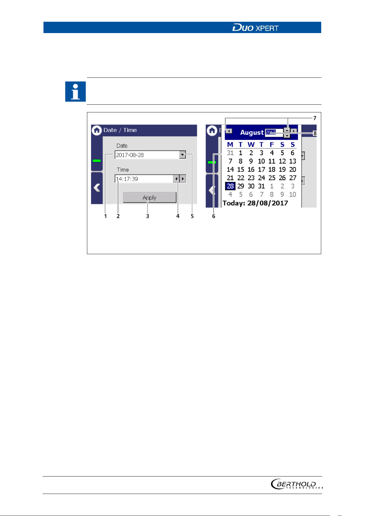
7 Main Menu Device Setup LB 470 Level
70
IMPORTANT
1
2
3
4
Display date
Display time
Button <Apply>
Arrow key Time
5
6
7
8
Selection arrow Date
Calendar
Arrow keys Month
Input box Year
Fig.
Set Date and Time
Device Setup | Setup | System | Date / Time
The date and time must always be set correctly so that all records (log files)
have the correct metadata.
The correct date is also indispensable for the decay compensation.
46 Date / Time, calendar
1. Click on the arrow key (Fig. 46, item 5) in order to set the date.
The calendar is opened (Fig. 46, item 6).
2. Click on the year number (Fig. 46, item 8) in order to enter the year.
3. Set the month (Fig. 46, item 7) by clicking on the arrow keys.
4. Set the day by clicking on a number in the calendar.
5. Change the time by clicking on the arrow keys (Fig. 46, item 4).
6. Click on <Apply> (Fig. 46, item 3), to accept the date and time settings.
56925BA2 Rev. 03, 11/2017
Page 71
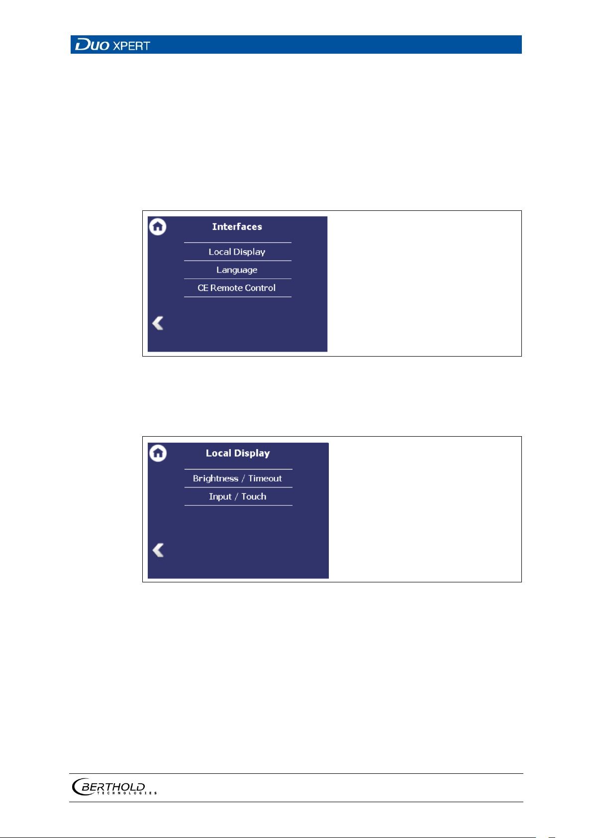
LB 470 Level 7 Main Menu Device Setup
71
Fig.
Fig.
Interfaces
Device setup | Setup | System | interfaces
You can adjust the following settings in the submenu ″Interfaces″ (Fig. 47):
• Local Display
• Brightness / Touch
• Input / Output
• Language
• CE Remote control
47 Menu ″Interfaces″
Local Display
Device setup | Setup | System | Interfaces | Local Display
48 Submenu "Local Display"
56925BA2 Rev. 03, 11/2017
Page 72
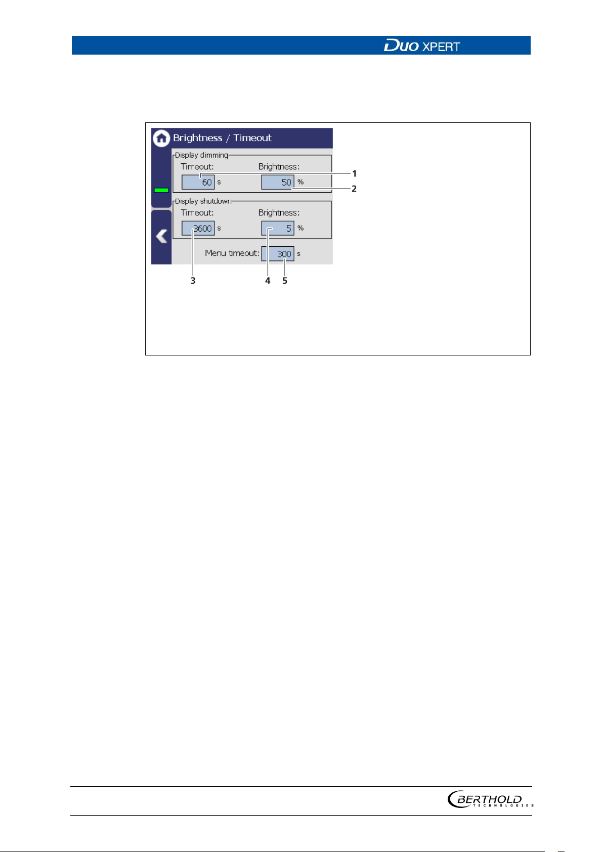
7 Main Menu Device Setup LB 470 Level
72
1
2
3
4
5
Input field ″Time out″
Input field ″Dimming″
Input field Display switch off ″Time out
Input field Display switch off ″Dimming
Input field menu time out
Fig.
Display dimming
Display shutdown
Menu Timeout
Brightness / Timeout
Device Setup | Setup | System | interfaces | Local Display | Brightness / Timeout
″
″
49 Brightness / Time out settings
“Time out” refers to the period of time during which the display is not operated.
The value “Time out display brightness” cannot be set greater than the value at
“Time out display switch-off”.
In the field Display dimming, clicking the input fields
allows the entering of the brightness (Fig. 49, item
2) in percent, that is set after expiry of the time (Fig.
49, item 1).
In the field Display shutdown, clicking the input
fields allows the entering of the brightness (Fig. 49,
item 4) in percent, that is set after expiry of the time
(Fig. 49, item 3).
Under "Menu Timeout" clicking on the input field
(Fig. 49, item 5) changes the time period (seconds) in
which the menu view changes to the standard view.
56925BA2 Rev. 03, 11/2017
Page 73
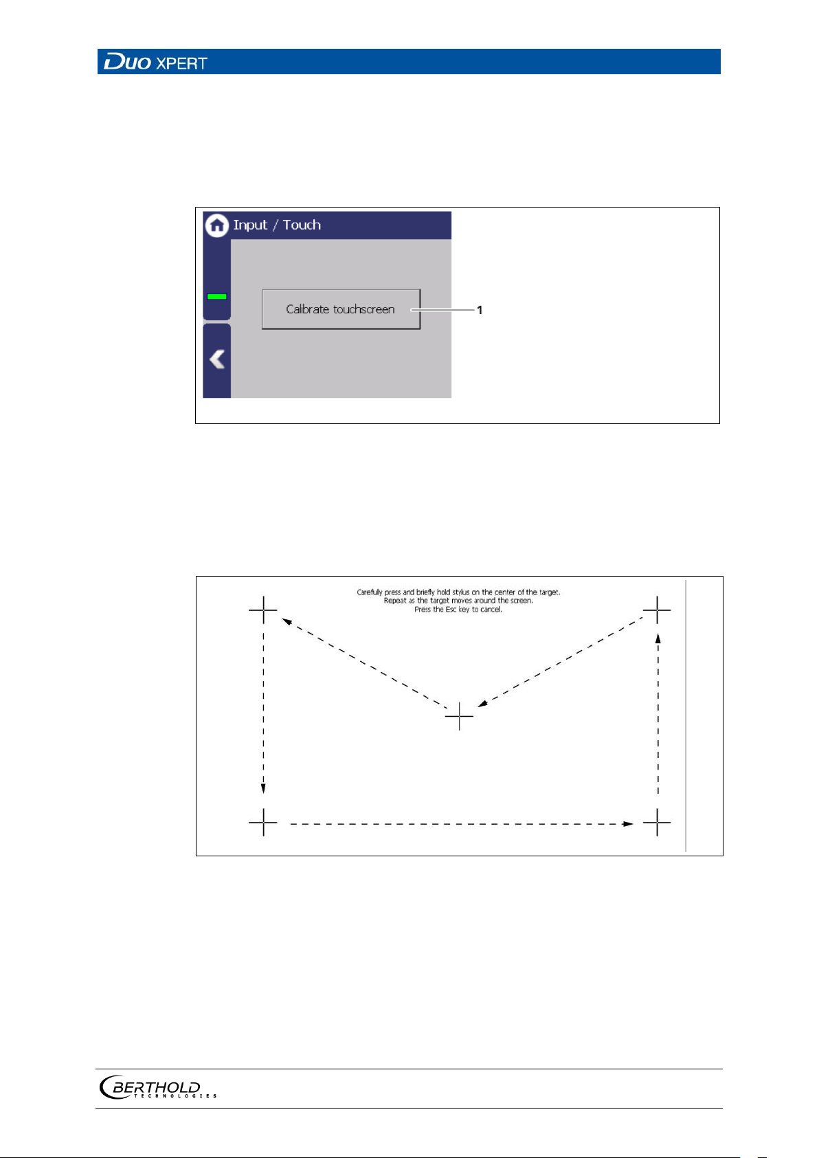
LB 470 Level 7 Main Menu Device Setup
73
1
Button <Calibrate touch screen>
Fig.
Fig.
Input / Touch
Device Setup | Setup | System | Interfaces | Local Display | Input / Touch | Calibrate
Touchscreen
The mouse pointer automatically becomes visible when a mouse is inserted into
the USB port.
50 Input/ Touch
Calibrate touch screen
The calibration may only be carried out with direct skin contact. Take gloves or any
other protective equipment off your hands.
51 System menu, Settings - Display (Calibrate touch display)
1. Click on <Calibrate touch screen>.
The calibration screen opens.
2. Press the middle of the displayed cross with your finger.
If you take your finger off the cross again, the cross jumps to the top left
corner.
56925BA2 Rev. 03, 11/2017
Page 74
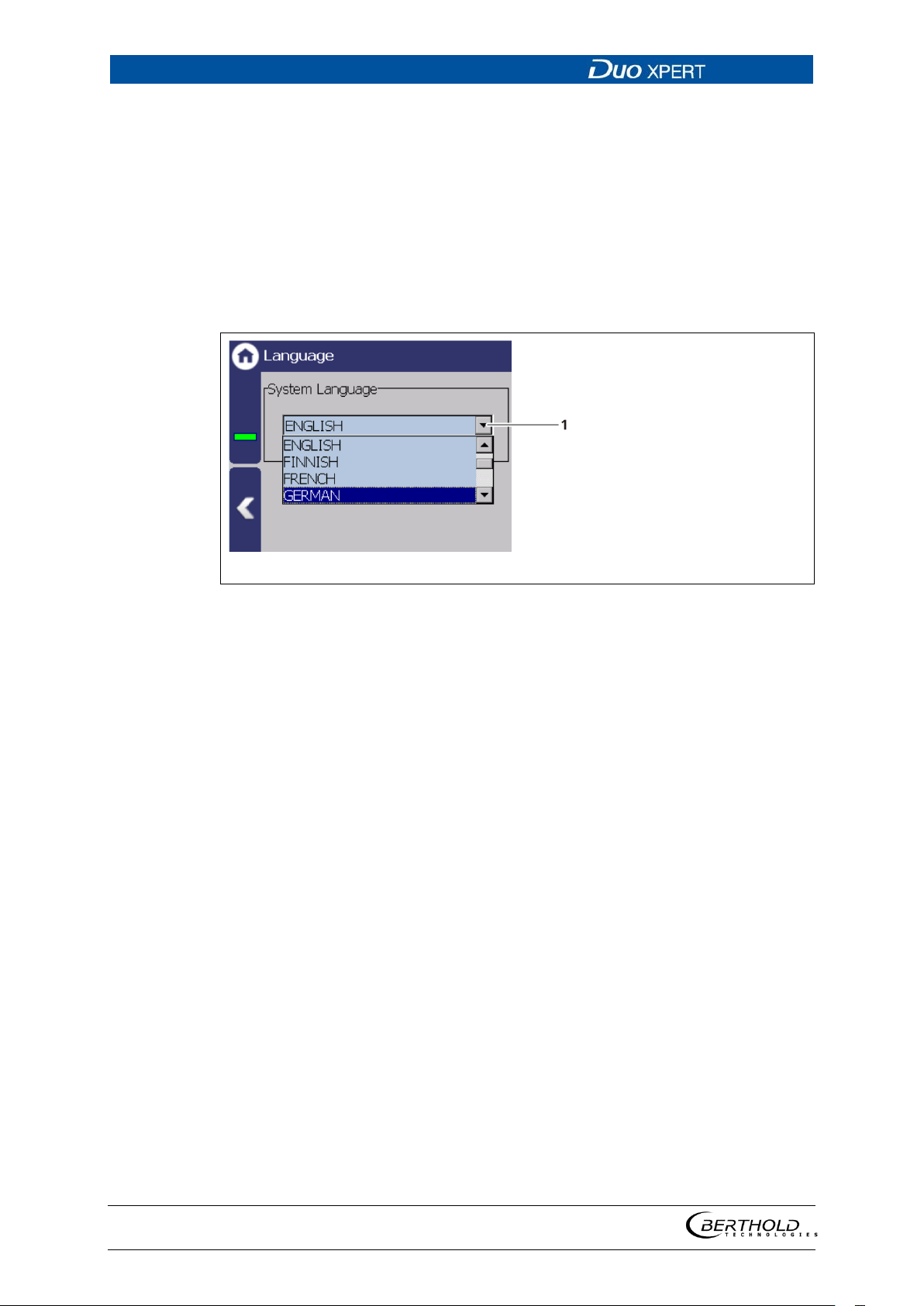
7 Main Menu Device Setup LB 470 Level
74
1
Selection arrow
Fig.
3. Repeat the process until the cross is no longer displayed and the calibration is
finished.
4. Confirm the calibration by clicking on the white screen to go back to "In-
put/Touch"
5. Execute a restart of the EVU after prompting.
Language
Device Setup | Setup | System | interfaces | Language
52 Language
Change system language
1. Click on the selection arrow (Fig. 52, item 1) and select a language.
A message window ″Restart″ appears.
2. Confirm with ″OK″ to restart the device.
The device is restarted and the language has been changed.
56925BA2 Rev. 03, 11/2017
Page 75
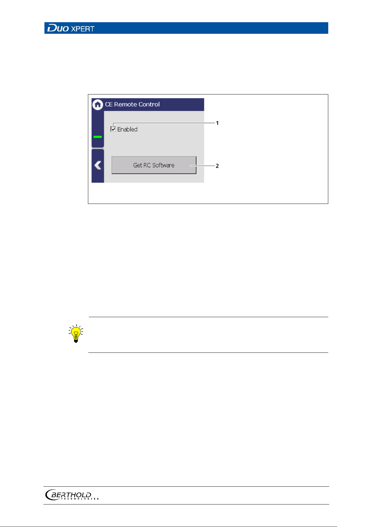
LB 470 Level 7 Main Menu Device Setup
75
1 2 Check box remote control ″Enabled″
Button <Copy RC software>
Fig.
Information
CE Remote Control
Device Setup | Setup | System | interfaces | Remote Control
By activating (Fig. 53, item 1) the CE Remote Control, the unit can be operated via
the network connection. The software of the remote control (RC software) is stored
on the device and can be copied to a USB storage device.
53 Remote Control
Copy RC software
1. Connect a USB storage device to the device (Fig. 3, item 5).
The USB storage device is recognised by the system after a few seconds and
the button <Copy RC software> (Fig. 53, item 2) can be clicked.
2. Click on the button <Copy RC software> (Fig. 53, item 2).
The software is copied to the USB storage device.
The RC software includes the file ″LB47xRem oteControl.exe″ and run s w ithout in-
stallation.
Operation of the RC software is described in Chapter “Remote Control Software” (see next but one chapter).
56925BA2 Rev. 03, 11/2017
Page 76
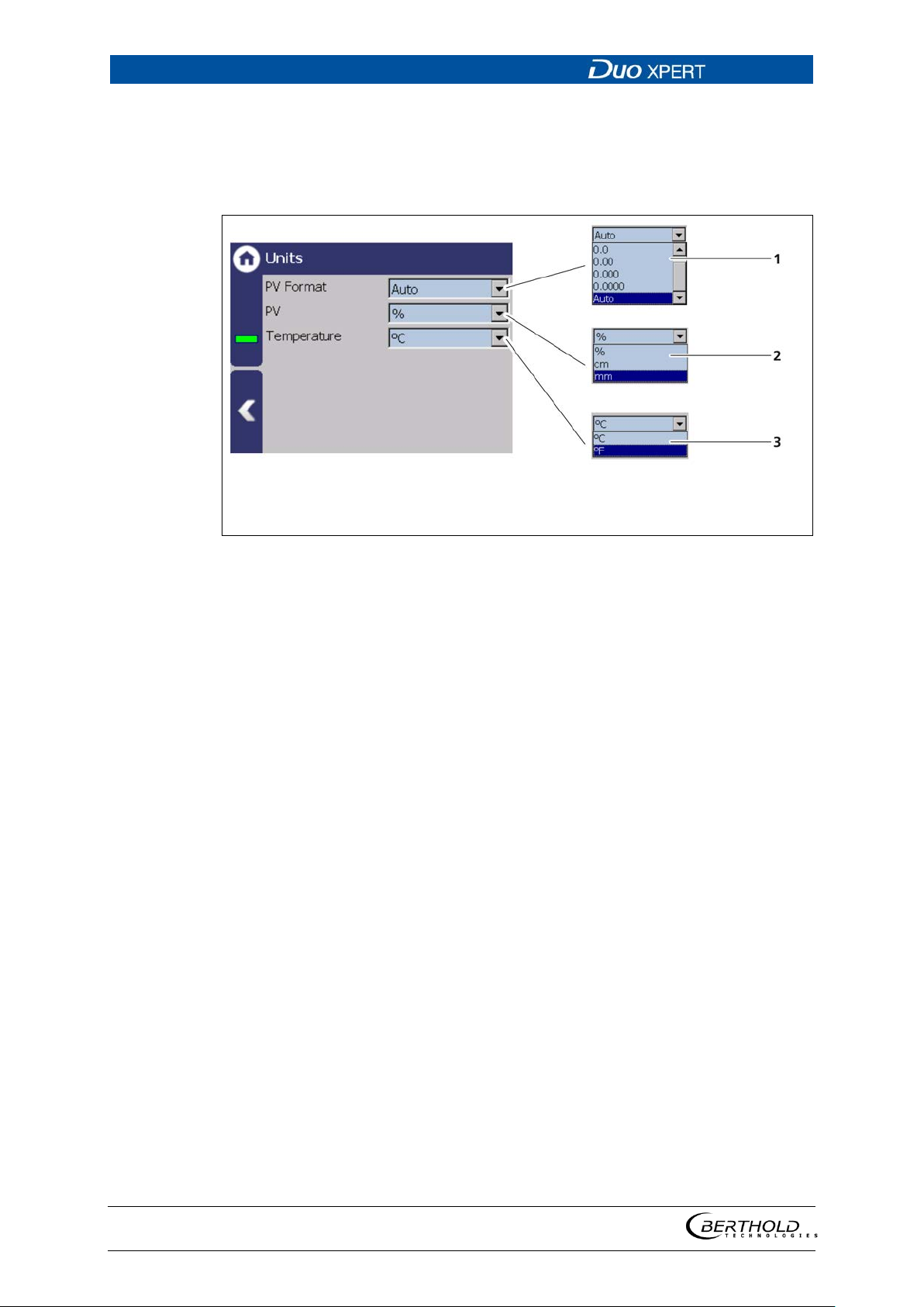
7 Main Menu Device Setup LB 470 Level
76
1
2
3
Selection ″PV Format″
Selection ″PV
Selection ″Temperature″
Fig.
Units
Device Setup | Setup | System | Units
Clicking on the individual selection arrow lists the available units for the measuring
value. The selected unit is shown in the standard display.
″
54 Units
56925BA2 Rev. 03, 11/2017
Page 77
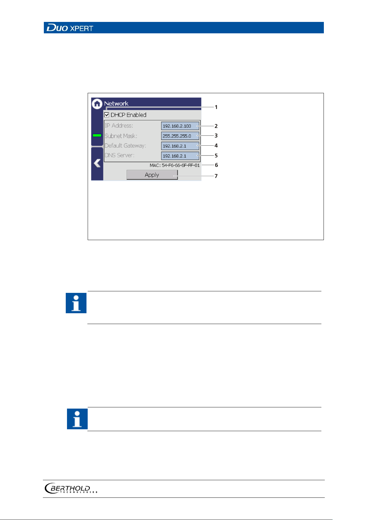
LB 470 Level 7 Main Menu Device Setup
77
1
2
3
4
5
6
7
Check box "DHCP active"
IP address
Subnet mask
Standard gateway
DNS server
MAC address
Button <Apply>
Fig.
IMPORTANT
IMPORTANT
Network
Device Setup | Setup | System | Network
In the Network settings submenu, you can make changes to the network settings.
The information can only be edited in the access level "Standard" (see chap. 7.2
Menu Access).
55 Network Settings
You can set the network address either manually or using DHCP (automatic assignment). To do this, check the "DHCP active" in the selection field (Fig. 55, item 1).
In the event of an automatic assignment of the IP address by a DHCP server,
you can only look at the given IP address. A modification of the IP address is
not possible. On this side, you can also read the MAC address of the device
(Fig. 55, item 6).
Manual settings:
1. Click on the text field (Fig. 55, item 2 - 5) to open the input field.
2. Enter the appropriate network addresses.
3. Confirm with the Enter key.
4. Click on <Apply> (Fig. 55, item 7) to adopt the network settings.
All settings performed must be confirmed by clicking on <Apply> so that the
settings become real.
56925BA2 Rev. 03, 11/2017
Page 78
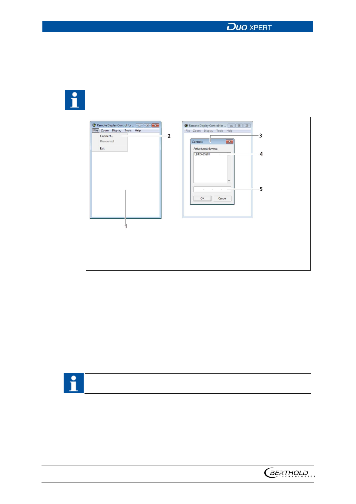
7 Main Menu Device Setup LB 470 Level
78
IMPORTANT
1
2
3
4
5
Programme Remote Control
Box <Connect…>
Window Connect
List of transmitters
Input box IP address
Fig.
IMPORTANT
Remote Control Software
If the EVU is connected to a network at the RJ45 socket (Fig. 3, item 2), the EVU
can be operated via a computer. The software can be loaded onto a USB storage
device (see Chapter “CE Remote Control”).
In order for the Remote Control to function, the selection check mark in the
menu "CE Remote Control" must be set to "Active" (Fig. 53, item 1).
56 Establishing connection to the EVU using the RC software
1. Click on "LB47xRemoteControl.exe", to start the programme.
The program starts (Fig. 56, item 1).
2. Click on the <File> tab and then on <Connect…> (Fig. 56, item 2), to estab-
lish a connection to the EVU.
A new window “Connect” is opened (Fig. 56, item 3) and the connected
transmitters are listed.
The IP address of the EVU must be in the same sub-network (Fig. 55, item 3) as
the network adapter of the computer (see previous Chapter “Network”).
3. Click on the identifier of the transmitter (Fig. 56, item 4) or enter the IP ad-
dress of the EVU in the input box (Fig. 56, item 5) (see Fig. 56, item 2).
4. Click on <OK>.
The connection to the EVU is established.
5. You can enlarge the view in the “Zoom” menu (2x,3x).
56925BA2 Rev. 03, 11/2017
Page 79
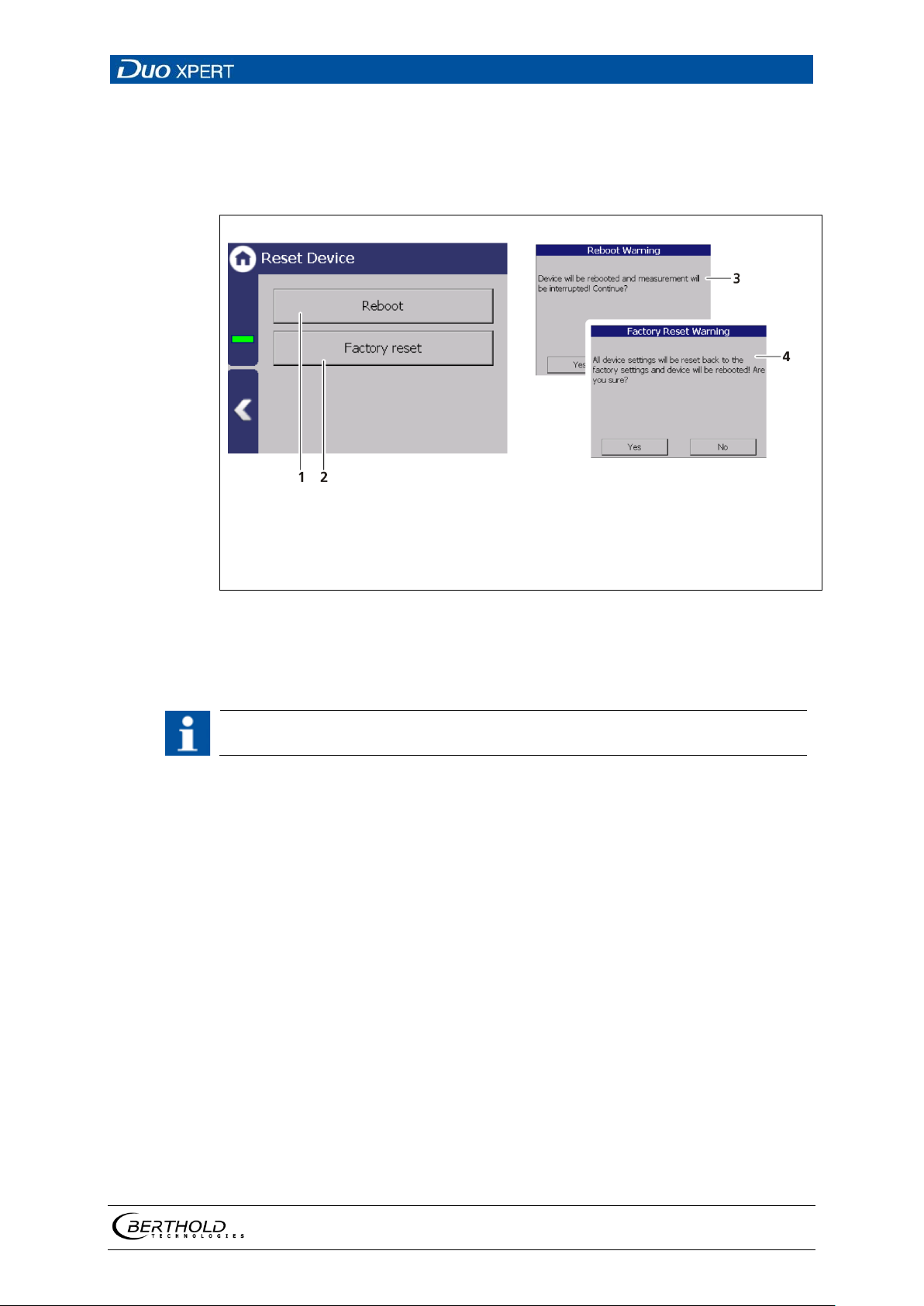
LB 470 Level 7 Main Menu Device Setup
79
1
2
3
4
Button Reboot
Button Factory settings
Window "Warning: Reboot"
Window "Warning: Factory Reset"
Fig.
IMPORTANT
Reset Device (evaluation unit)
Device settings | Setup | System | Reset Device
The evaluation unit can be restarted and reset to factory settings in the submenu
"Reset device".
57 Reset device
Restart the device
The measurement is interrupted during a restart!
1. To restart the device, click the button <Restart> (Fig. 57, item 1).
A window with a warning "Restart" (Fig. 57, item 3) opens.
2. Click on <Yes> to confirm.
The device is restarted.
56925BA2 Rev. 03, 11/2017
Page 80
7 Main Menu Device Setup LB 470 Level
80
IMPORTANT
IMPORTANT
Reset device (Factory Reset)
When there is a reset to factory settings, all data logs are deleted and all userdefined configuration settings are reset!
1. To reset the evaluation unit to the factory settings, click the button <Factory
settings> (
A window with the warning "Factory settings" (Fig. 57, item 4) opens.
Fig. 57, item 2).
2. Click on <Yes> to confirm.
The device is reset to factory settings and restarts.
If error M102 appear, the device possibly must be reset twice.
56925BA2 Rev. 03, 11/2017
Page 81
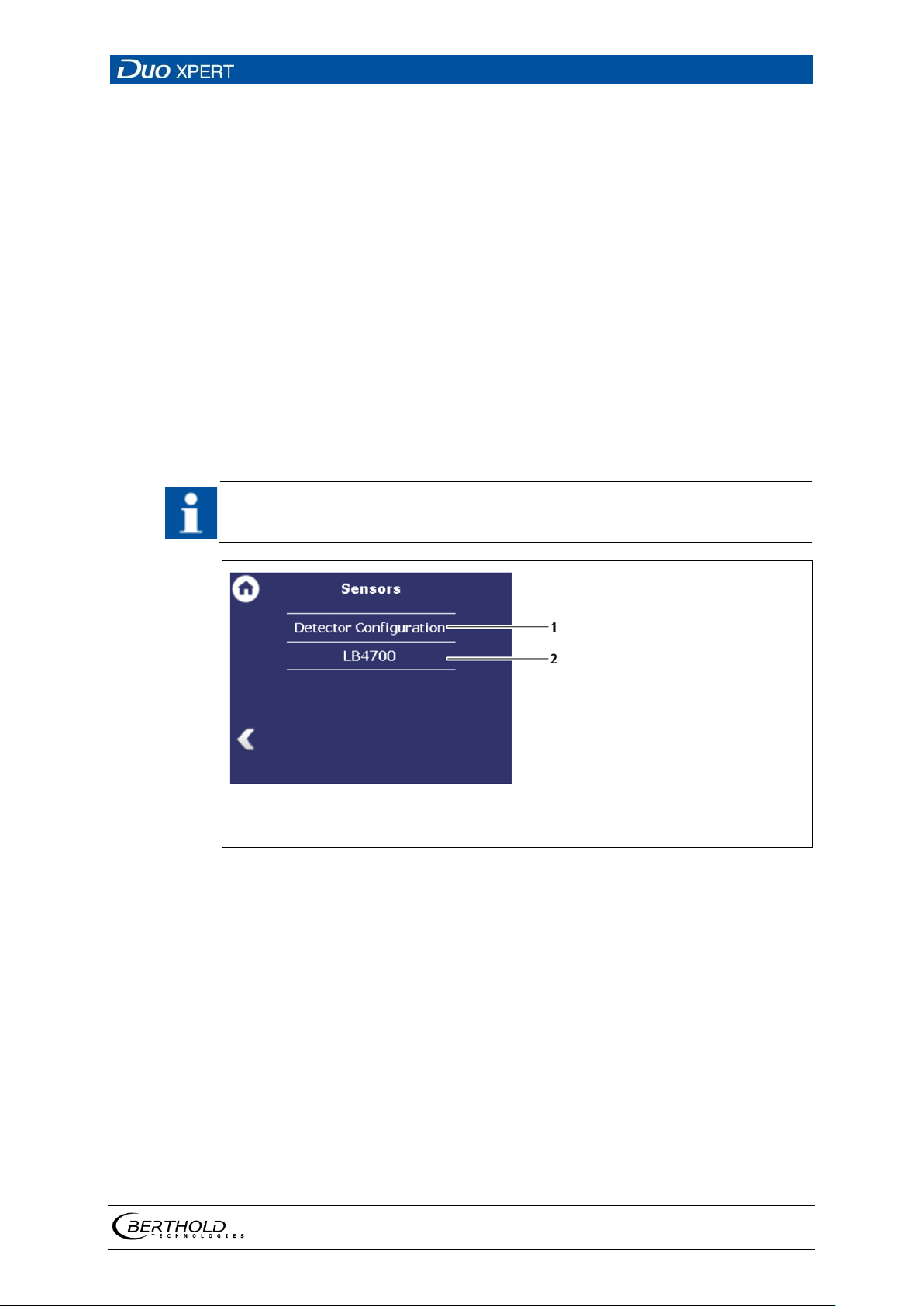
LB 470 Level 7 Main Menu Device Setup
81
IMPORTANT
1
2
Detector configuration
Detector name (as entered in the detector description)
Fig.
7.3.2 91BSensors
Device settings | Setup | Sensors
You can perform the following settings and read information in the submenu Sensors:
• Detector configuration (Fig. 58, item 1)
o Add / Remove detectors
o Settings of the detectors
• Configuration of the respective detector (Fig. 58, item 2)
o Overview
o Plateau
o Temperature
o High voltage
o Detector Service
If the system does not detect a detector, then the sub-menu “Detector” cannot
be selected.
58 Menu "Sensors"
56925BA2 Rev. 03, 11/2017
Page 82
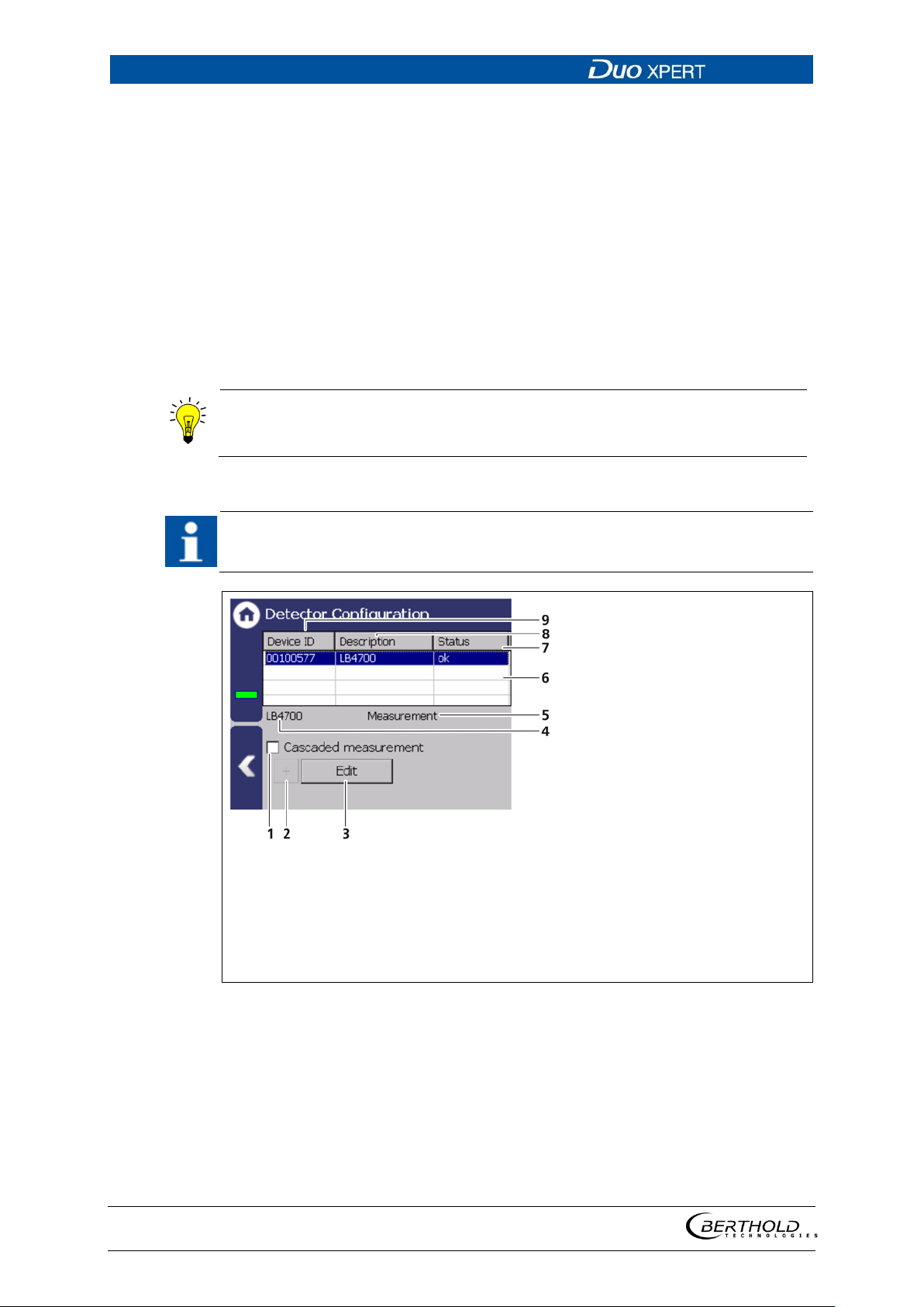
7 Main Menu Device Setup LB 470 Level
82
Information
Information and settings for the detector are in the individual detector menu
(
IMPORTANT
1
2
3
4
5
Selection box “Cascaded measurement”
Button < + > to add Detector
Button < Edit >
Type of selected detector
Measuring task for the selected
detector
6
7
8
9
List of the Detectors
Status of the Detector
Description of the Detector
Device ID of the detector
Fig.
Detector configuration
Device settings | Setup | Sensors | Detector configuration
In the sub-menu “Detector configuration” the detectors for the measuring system
are added and configured. Only configured detectors are listed and shown in the
menu (Fig. 58). When a detector is selected (Fig. 59, item 6), the detector type (Fig.
59, item 4) and measuring task (Fig. 59, item 5) are shown.
Clicking the box <Edit> (Fig. 59, item 3) selects the type of detector and changes
the description. The boxes <+> and <-> can be used to add and remove detectors
for cascading measurement.
Evaluation of the measurement data from detectors type LB44xx and LB54xx is only
possible with Master units.
Fig. 62).
In systems with a single detector the device ID is determined automatically and
listed. The description can be edited by clicking on <Edit> (Fig. 59, item 3).
59 Detector configuration
56925BA2 Rev. 03, 11/2017
Page 83
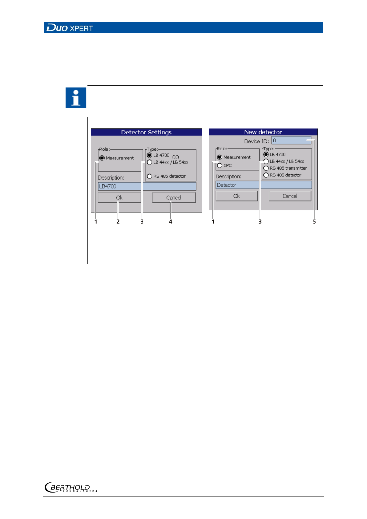
LB 470 Level 7 Main Menu Device Setup
83
IMPORTANT
A B
1
2
3
4
5
Field "Role"
Button <Ok>
Field "Type"
Button <Cancel>
Input field Device (Unit ID)
Fig.
Measurement
GPC
LB4700
LB44xx/LB54xx
RS 485 transmitter
RS 485 detector
Description
Detector Settings
The settings of a configured detector are edited by selecting and clicking on <Edit>
(Fig. 59, item 3).
For systems with a single detector, window A is displayed. For cascaded systems, window B is displayed.
60 Detector Settings
The selection "Measurement" determines the
level of the container.
The selection "GPC" (Gas Properties Compensation) determines the gas density in order to
compensate these for a precise measurements.
Detector of type LB4700 (A LB 4700 detector can
be connected either to the master unit itself or
to a slave module).
Detector of the type LB44xx and LB54xx (no device ID; can capture measurement data only with
master EVU)
By selecting "RS 485 transmitter", other LB 470
master units can be used to perform cascaded
measurements. This way multiple detectors of
different designs can be integrated into a measurement system. Please refer to the instructions
in the following chapters.
With the selection “RS 485 detector” it is possible to connect a specific detector via the RS 485
interface.
Detector description. Also used for error messages, logs and in the menu structure (Fig. 58).
56925BA2 Rev. 03, 11/2017
Page 84
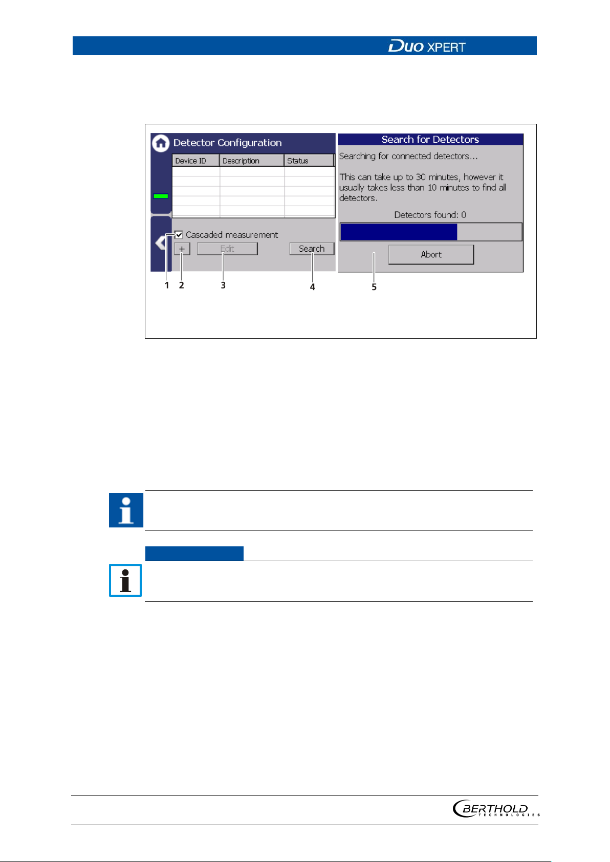
7 Main Menu Device Setup LB 470 Level
84
1
2
3
Selection box “Cascaded measurement”
Button < + >
4 5 Button <Search>
Fig.
IMPORTANT
NOTICE
Configure a cascaded system
Note the arrangement of the system components during configuration (see chapter 3.2 Measuring Principle).
Window “Search detectors”
Button <Edit>
61 Configure cascaded system
1. If the connection to the EVU (Master-Slave) is correct, the detectors type
LB47xx are detected and incorporated automatically. Click on the button
<Search> to incorporate connected detectors.
2. Activate the selection box “Cascaded measurement” (Fig. 61, item1).
3. Set the appropriate function for each detector (Fig. 60).
Both LED (Rx, Tx) indicators flash with proper installation and configuration of
a detector on the slave module.
Calibration must be performed according to the configuration of the entire
measuring system.
56925BA2 Rev. 03, 11/2017
Page 85
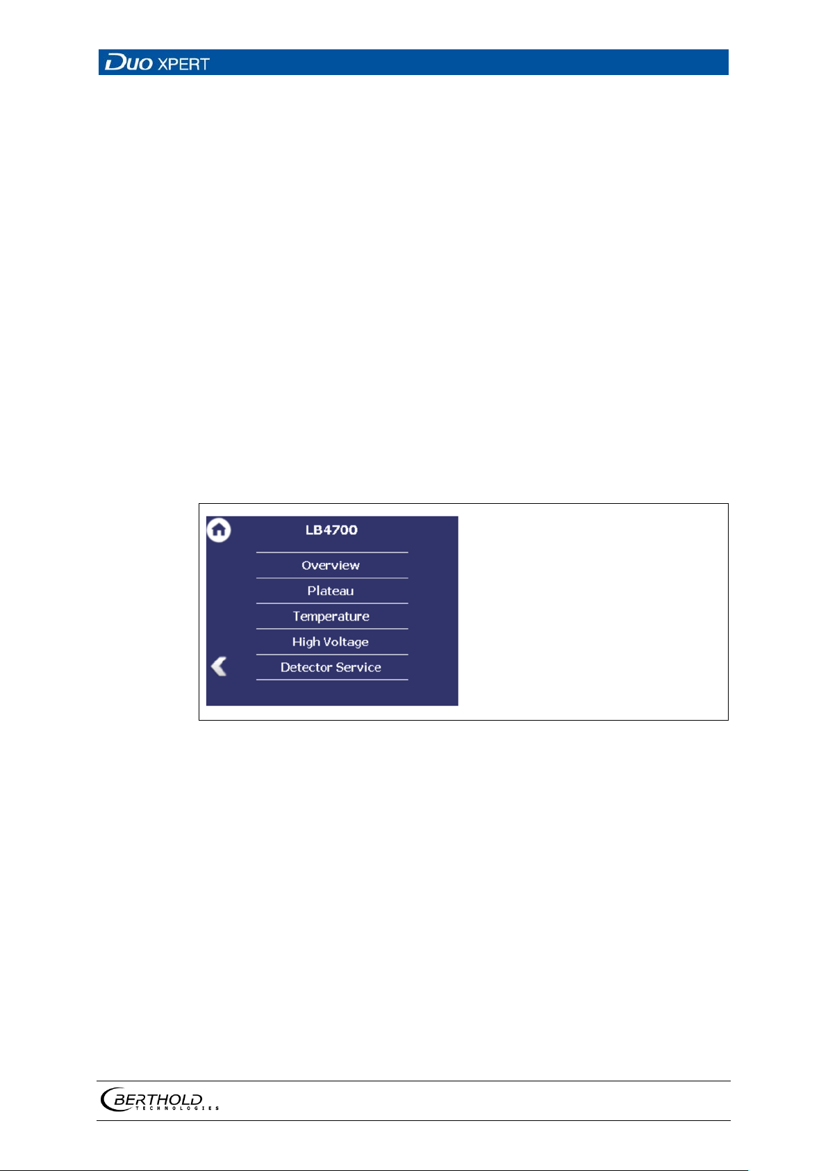
LB 470 Level 7 Main Menu Device Setup
85
Fig.
Detector settings
Device settings | Setup | Sensors | [NAME DETECTOR]
You can adjust the following settings and read information in the submenu of the
respective detector:
• Overview of count rate, HV value and temperature
• Plateau
o Plateau Settings
o Plateau Measurement
o Plateau Table
o Plateau Curve
• Current temperature and extreme values
• High voltage
o Detector Type
o HV Settings
• Detector Service
o Device information
o Event Log
o Event Overview
o Reset Device
62 Submenu "Detector"
56925BA2 Rev. 03, 11/2017
Page 86
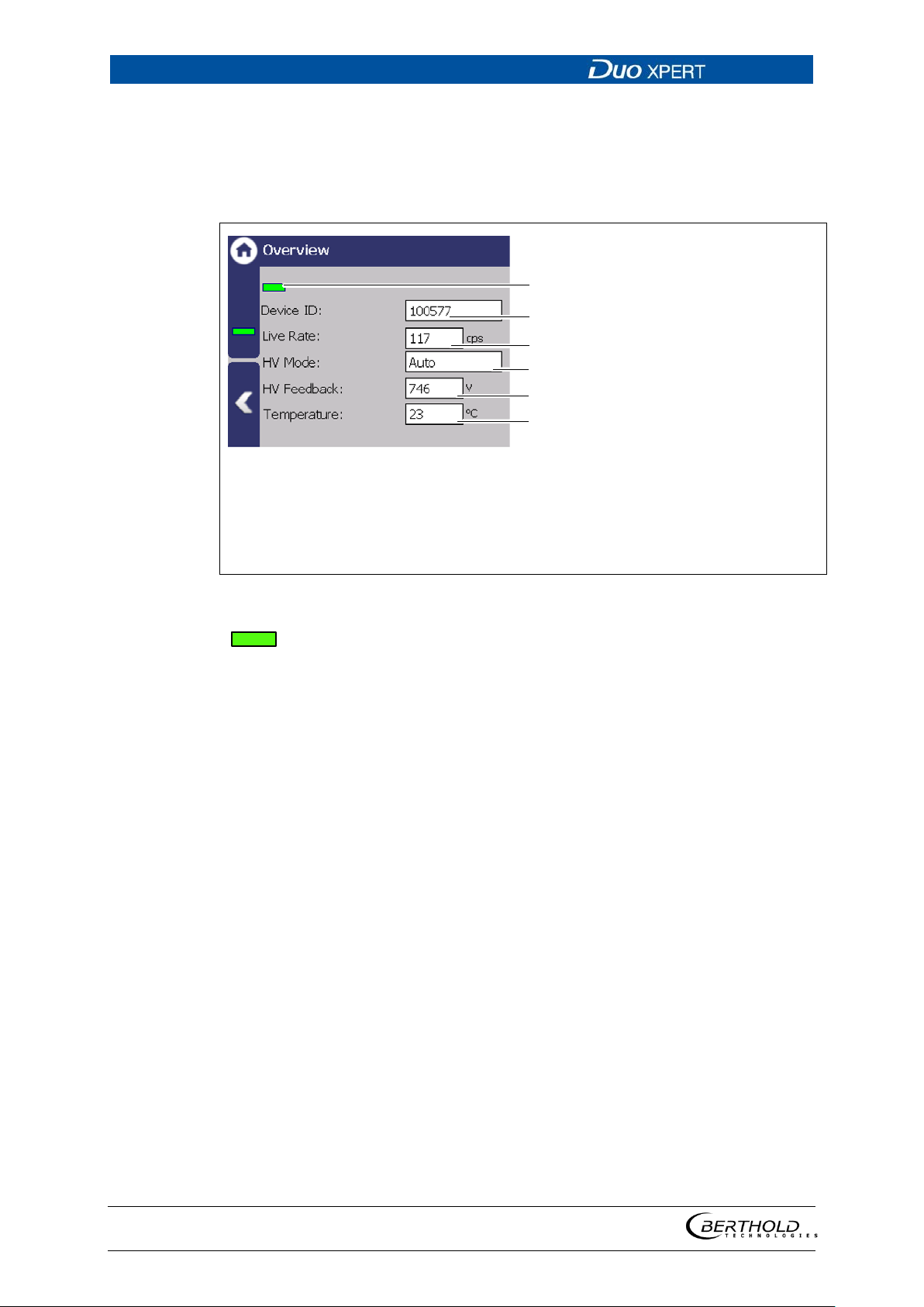
7 Main Menu Device Setup LB 470 Level
86
1
2
3
4
5
6
Status information of the detector
Device ID
Live rate [cps]
HV mode
HV feedback [V]
Temperature [°C]
Fig.
A green bar appears with error-free status of the detecDevice ID
Shows the ID of the detector.
Live count rate
The "Live count rate" (Fig. 63, item 3) displays the cur-
HV mode
In the field "HV mode" (Fig. 63, item 4), the HV mode
HV Feedback
The field "HV Feedback" (Fig. 63, item 5) displays the
Temperature
The field "Temperature" (Fig. 63, item 6) indicates the
2
1
3
4
5
6
Detector settings: Overview
Device settings | Setup | Sensors | [NAME DETECTOR] | Overview
All important parameters and measured values of the detector are clearly displayed
in the submenu "Overview".
63 Overview detector information
tor (Fig. 63, item 1).
rent, unfiltered count rate.
is displayed, which is chosen under Device settings |
Setup | Sensors | | NAME DETECTOR] | High voltage | HV
settings.
actual measured value in volts.
current temperature of the detector in C°.
56925BA2 Rev. 03, 11/2017
Page 87
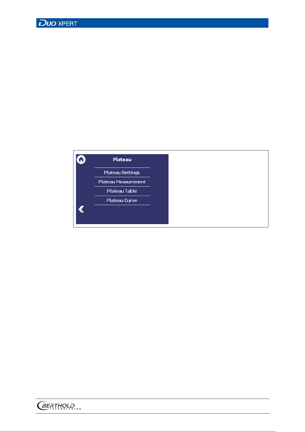
LB 470 Level 7 Main Menu Device Setup
87
Fig.
Detector settings: Plateau
Device settings | Setup | Sensors | [NAME DETECTOR] | Plateau
The plateau provides information on whether the detector is stable. A plateau
measurement is therefore only carried out when the measured value drifts, or
other doubts exist about the function of the detector. Panel measurement can help
narrow down the possible cause of the problem.
The high voltage necessary for the operation of the photomultipliers is increased
stepwise for the plateau recording and the pulse rate measured after each increase.
The determined plateau curve is displayed on a diagram. The pulse rate increases
with increasing voltage. This must form a unique plateau. If a too short or too steep
plateau is detected, the detector is operating in an unstable manner. The submenu
"Plateau" (Fig. 64) leads to the plateau measuring and the display of plateau values.
Please contact your responsible service or sales partner, or Berthold directly, so that
they can get a qualified assessment to the measured plateau.
64 Menu "Plateau"
56925BA2 Rev. 03, 11/2017
Page 88
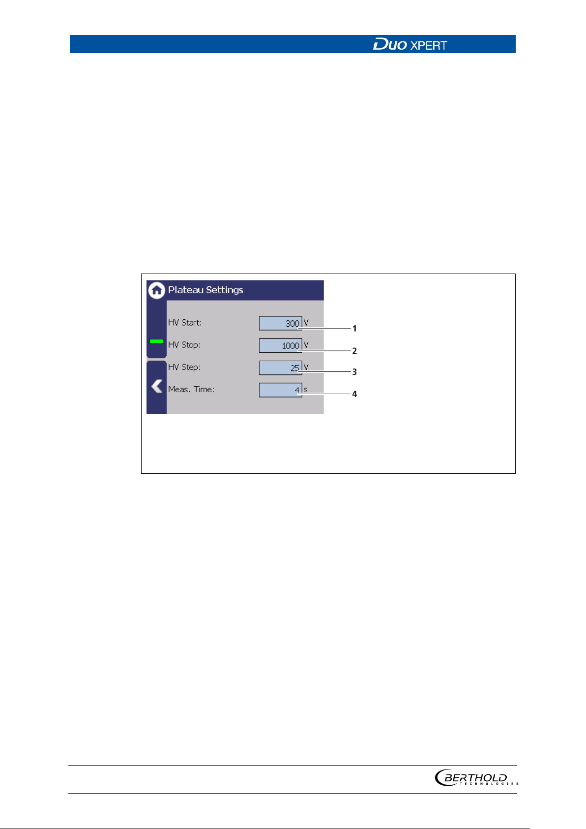
7 Main Menu Device Setup LB 470 Level
88
HV start / HV stop
Defining the range of the plateau recording.
HV step
Specifies the step (interval) between two meas-
Measuring time
Identifies the time that is used per measuring
1
2
3
4
Input field HV start value in volts
Input field HV end value in volts
Input field HV increment in volts
Input field measuring time in seconds
Fig.
Plateau Settings
Device settings | Setup | Sensors | [NAME DETECTOR] | Plateau | Plateau settings
The values in the submenu "Plateau settings" are pre-set by Berthold on delivery
and can be used in most situations.
You have the following settings options in the submenu "Plateau Settings":
uring points.
point for the counting of the count rate.
65 Plateau settings
1. Click on the corresponding text field.
The input field opens.
2. Change to the keypad and enter the value.
3. Confirm with the Enter key.
The values for the recording plateau have been changed.
56925BA2 Rev. 03, 11/2017
Page 89
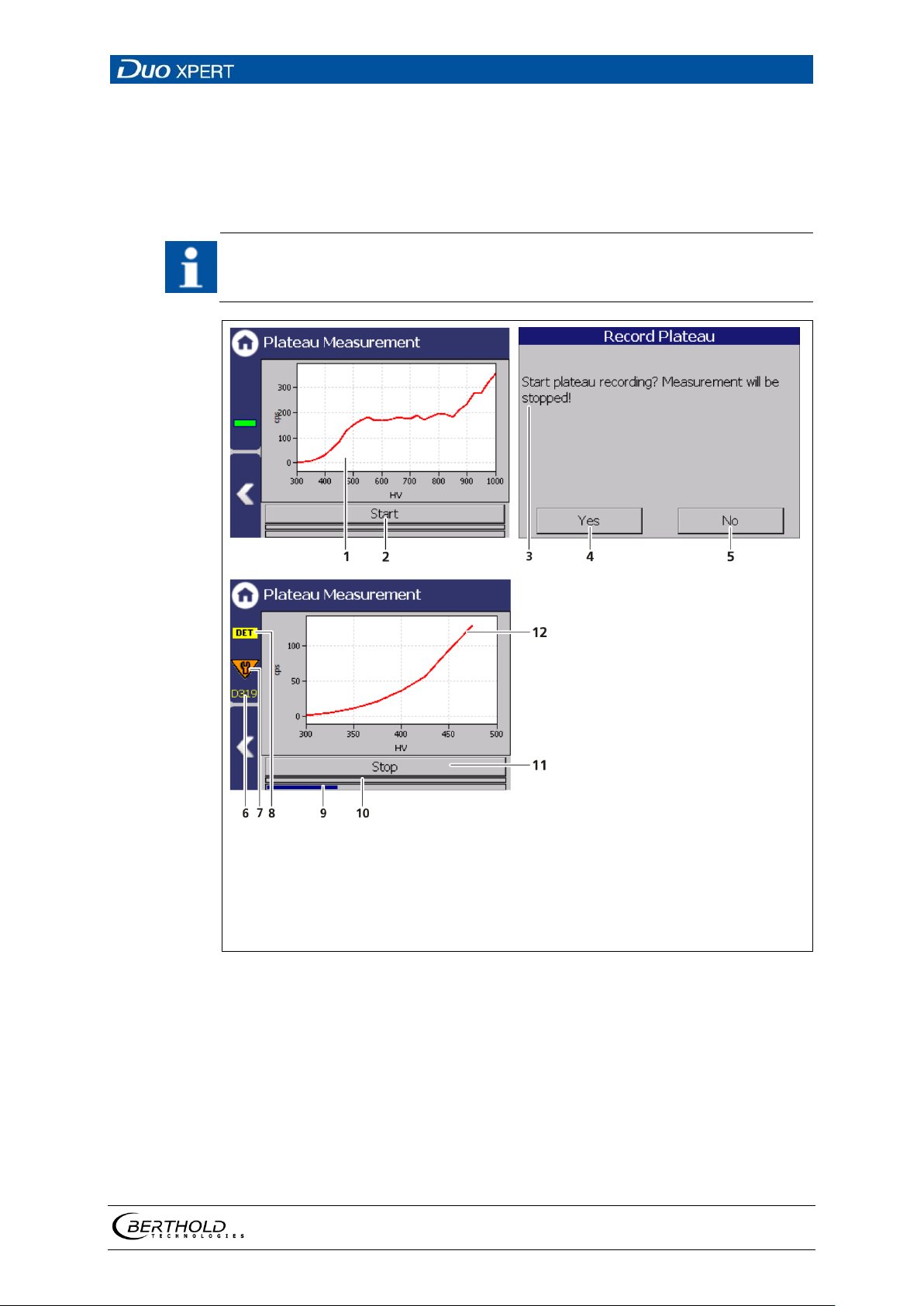
LB 470 Level 7 Main Menu Device Setup
89
IMPORTANT
1
2
3
4
5
6
Plateau curve
Button <Start>
Window "Record plateau"
Button < Yes >
Button <No>
Notice Code 505
7
8
9
10
11
12
Notice Maintenance
Notice DET
Progress bar measuring process
Progress bar measuring step
Button <Stop>
New plateau curve
Fig.
Perform Plateau Measurement
Device settings | Setup | Sensors | [NAME DETECTOR] | Plateau | Plateau Measurement
The environmental conditions and the dose rate must be constant during the
plateau recording.
Observe the operating manual of the detector!
66 Recording a plateau curve
1. Click on < Start > (Fig. 66, item 2) to perform a plateau measurement.
The confirmation message "Record plateau" (Fig. 66, item 3) opens.
2. Confirm with < Yes > (Fig. 66, item 4).
The EVU switches to mode "DET" (Fig. 66, item 8) and the current measure-
ment is stopped.
56925BA2 Rev. 03, 11/2017
Page 90
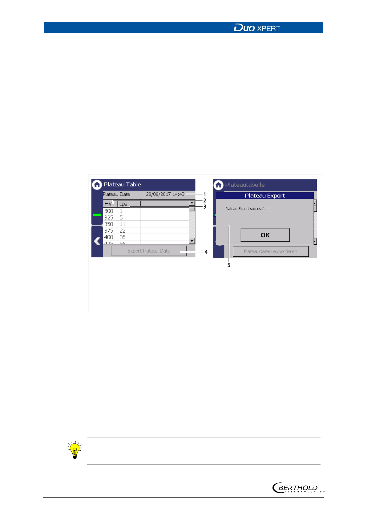
7 Main Menu Device Setup LB 470 Level
90
1
2
3
4
5
Date and time of measurement recording
High voltage (HV) in volts
Count rate in the measurement channel (cps)
Button <Export plateau data>
Window “Export successful”
Fig.
Information
The file name is derived from "Plateau",
process (PlateauYYYYMMDD_hr_min_sec.txt).
The information (Fig. 66, item 6 - 8) from the plateau measurement are dis-
played in the status information. The LED Run flashes on the EVU during the
plateau measurement. The LED "Warning" LED lights up at the same time.
If you click on the < Stop > button during the measurement, the measuring
process is interrupted. The measurement data are invalid and will be deleted.
The recorded values are read and entered into the table (Fig. 67), the plateau
curve (Fig. 68) is drawn and stored automatically.
Plateau Table
Device settings | Setup | Sensors | [NAME DETECTOR] | Plateau | Plateau Table
The data from each measurement point are listed in the plateau table. The data
from the plateau table can be exported to a USB memory device.
67 Plateau table
Export plateau data
1. Connect a USB storage device to the device (Fig. 3, item 5).
The USB memory device is recognised by the system after a few seconds and
the button <Export plateau data> can be clicked.
2. Click on the button <Export plateau data> (Fig. 67, item 4).
The values of the plateau measurement have been stored in a .txt file.
3. Confirm the message with <OK>.
the date and time of the measurement
56925BA2 Rev. 03, 11/2017
Page 91
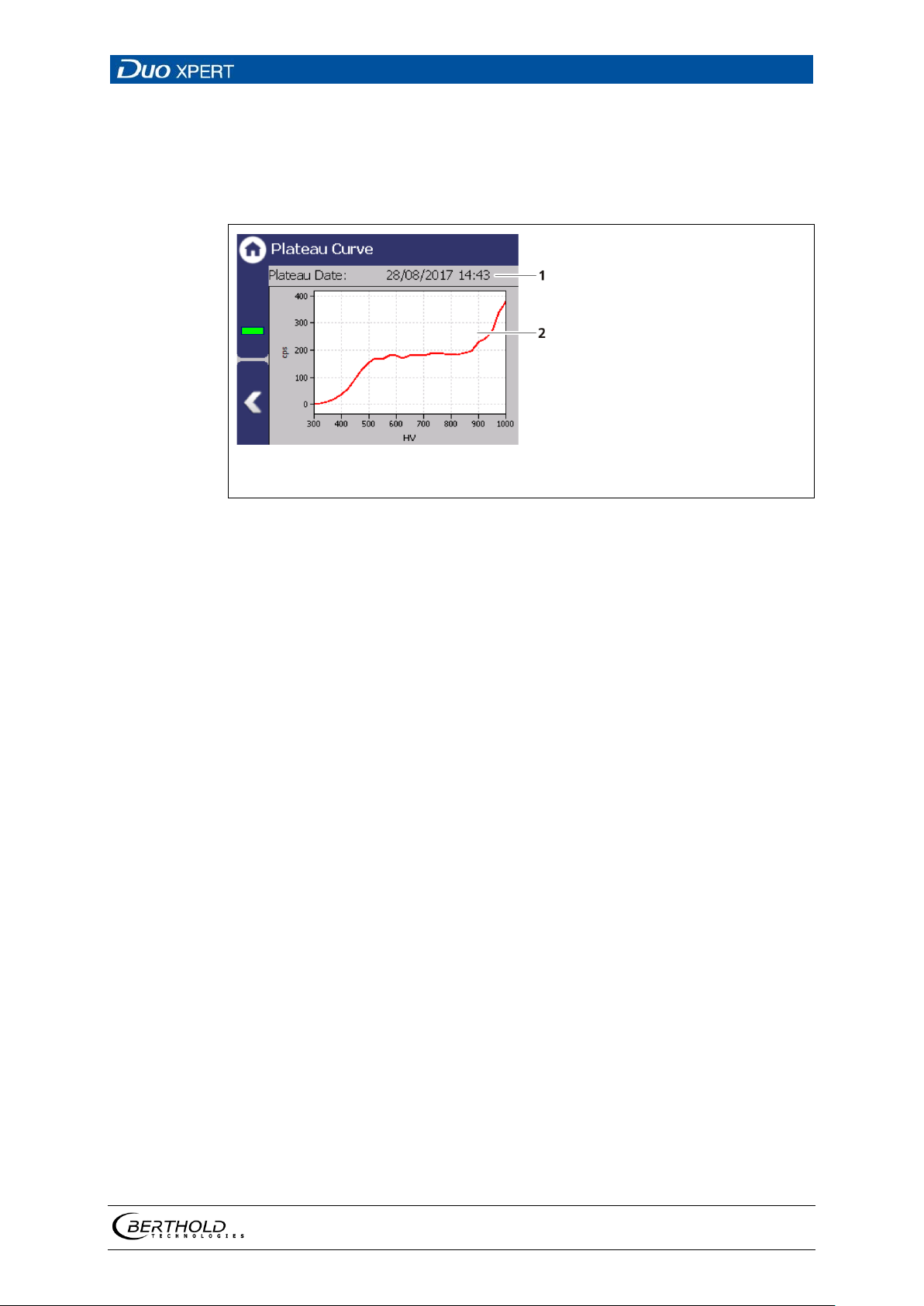
LB 470 Level 7 Main Menu Device Setup
91
1 2 Date and Time of measurement recording
Characteristic curve
Fig.
Plateau Curve
Device settings | Setup | Sensors | [NAME DETECTOR] | Plateau | Plateau Curve
The mapped characteristic curve (Fig. 68, item 2) of the last complete plateau measurement is displayed in the submenu "Plateau curve".
68 Plateau curve
56925BA2 Rev. 03, 11/2017
Page 92
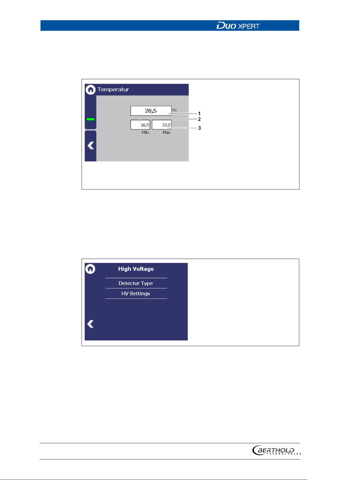
7 Main Menu Device Setup LB 470 Level
92
1
2
3
Current temperature of the detector [°C]
Maximum measured temperature [°C]
Minimum measured temperature [°C]
Fig.
Fig.
Detector settings: Temperature
Device settings | Setup | Sensors | [NAME DETECTOR] | Temperature
The current temperature and the extreme values of the detector is displayed in the
submenu "Temperature".
69 Temperature display of the detector
Detector settings: High Voltage
Device settings | Setup | Sensors | [NAME DETECTOR] | High Voltage
You can select the detector code and make settings for high-voltage regulation in
the submenu "High Voltage" of the respective detector.
70 Submenu "High Voltage"
56925BA2 Rev. 03, 11/2017
Page 93
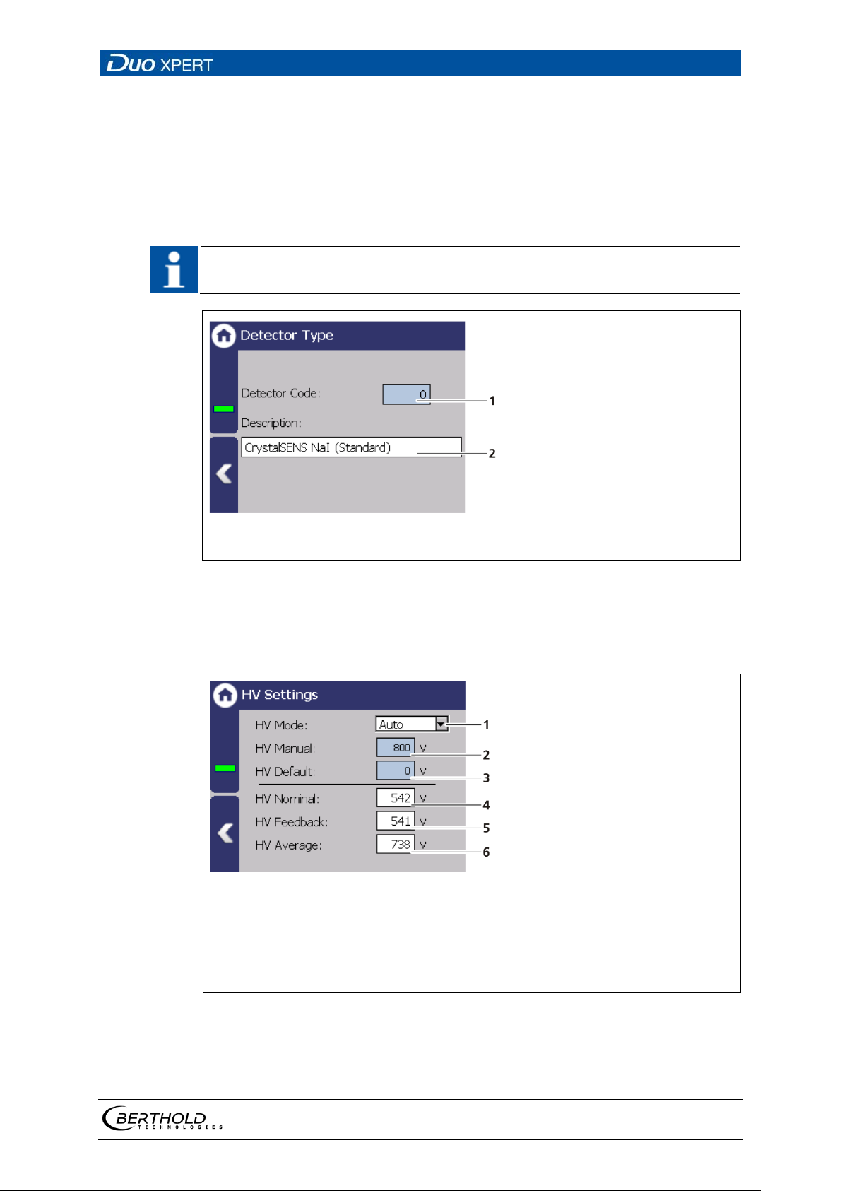
LB 470 Level 7 Main Menu Device Setup
93
IMPORTANT
1 2 Input field Detector code
Description of the scintillator type
Fig.
1
2
3
4
5
6
Selection High voltage mode "Auto" / "Manual"
Input field Manual high voltage
Input field HV Default (starting value of the high voltage regulation)
Display setting value high voltage
Display actual value high voltage
Display average high voltage
Detector settings: High Voltage | Detector Type
Device settings | Setup | Sensors | [NAME DETECTOR] | High Voltage | Detector Type
Internal device parameters are adjusted to suit the size of the used scintillator by
setting the detector code. The correct detector code is already set at the factory
and a change is not normally required.
A table with the detector code to be used is in the operating manual of the detector.
71 Detector Code: Setting the scintillator type
Detector settings: High voltage | HV Settings
Device settings | Setup | Sensors | [NAME DETECTOR] | High Voltage | HV Settings
Fig. 72 Submenu "Settings"
56925BA2 Rev. 03, 11/2017
Page 94
7 Main Menu Device Setup LB 470 Level
94
NOTICE
NOTICE
Default HV is preset by BERTHOLD. A subsequent change is not usually necessary. The default value HV = 0 may only be set for testing purposes. An incorrect
setting may cause malfunction.
It is not recommended to use the "Manual" mode as a normal operating mode
for high-voltage control. "Manual" should only be used for service purposes.
Make HV settings
1. Click on the selection arrow (Fig. 72, item 1) in order to set the desired HV
mode (auto or manual).
AUTO: The optimum high-voltage supply of the photomultiplier is automati-
cally determined and set by the device.
MANUAL: The high voltage is maintained at a fixed, user-entered value (Fig.
72, item 2).
2. Click in the input field "HV Default" (Fig. 72, item 3) to open the input field.
3. Enter the desired starting value for the high-voltage regulation.
4. Confirm with the Enter key.
56925BA2 Rev. 03, 11/2017
Page 95
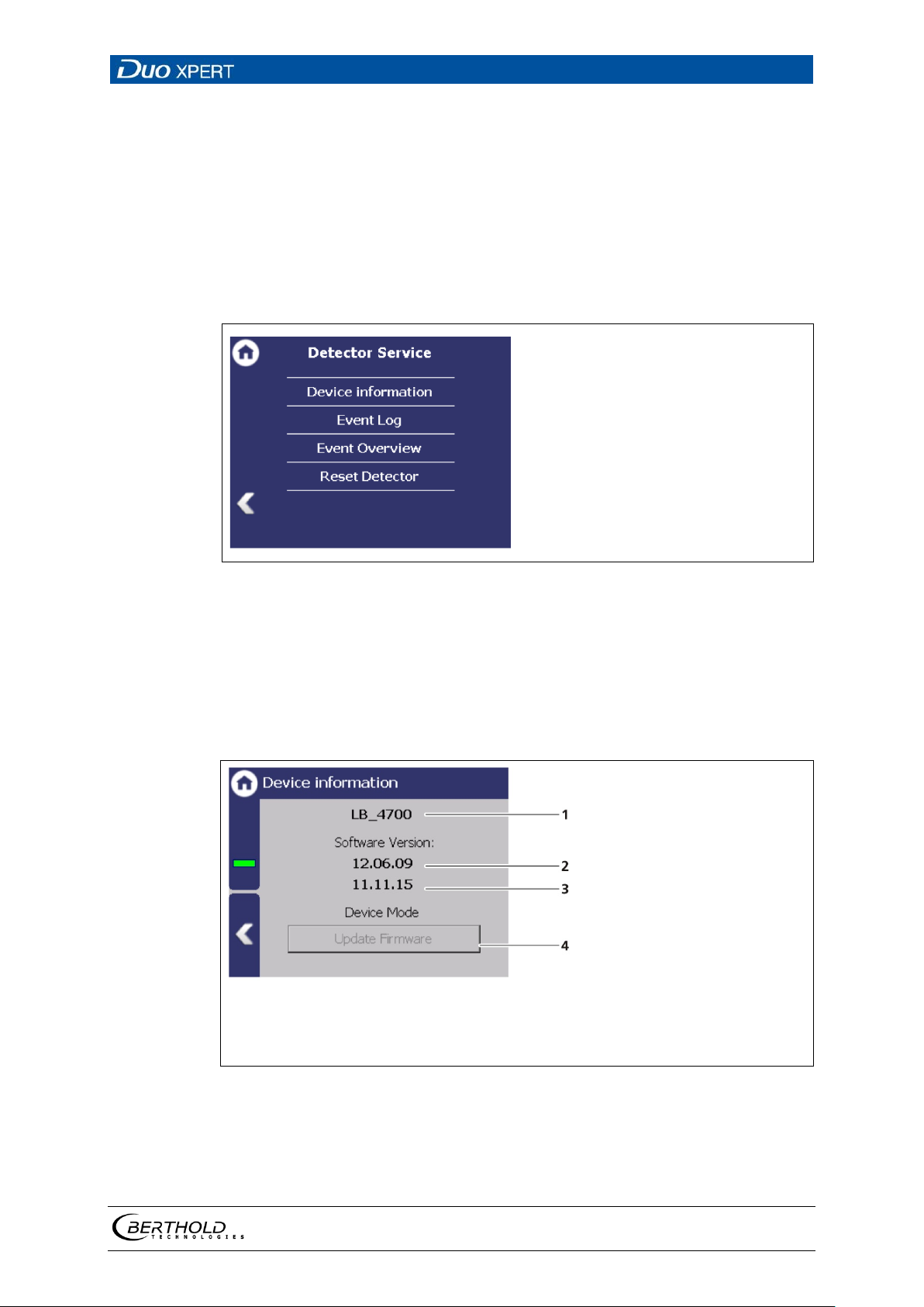
LB 470 Level 7 Main Menu Device Setup
95
Fig.
1
2
3
4
Detector type
Software version x
Software version
Button <Firmware Update>
Fig.
Detector settings: Detector Service
Device settings | Setup | Sensors | [NAME DETECTOR] | Detector Service
You can adjust the following settings and read information in the submenu "Service":
• Device information
• Event Log
• Event overview
• Reset Detector
73 Menu "Detector Service"
Detector settings: Service | Device information
Device settings | Setup | Sensors | [NAME DETECTOR] | Detector Service | Device information
This submenu shows you the type of detector (Fig. 74, item 1) as well as an overview
of the software version (Fig. 74, item 2, item 3) of the detector.
74 Device Information
56925BA2 Rev. 03, 11/2017
Page 96
7 Main Menu Device Setup LB 470 Level
96
NOTICE
Tipp
The current software versions can be downloaded from the Berthold website
(www.berthold.com).
IMPORTANT
NOTICE
An update of the firmware of the detector may take 1 hour and may only be
performed by qualified specialists.
In order for the system to detect the update file it must not be located in an
index in the USB storage device.
Perform firmware update
1. Save the current update file of the firmware of the detector on a USB stor-
age device.
2. Connect a USB storage device to the device (Fig. 3, item 5).
3. The USB storage device is recognised by the system after a few seconds and
the <Firmware Update> (
Fig. 74, item 4) button can be clicked.
4. Click on the button <Firmware Update> (Fig. 74, item 4).
5. The update is performed.
Berthold recommends a test or a calibrating the current outputs whenever if a
software update has been carried out.
56925BA2 Rev. 03, 11/2017
Page 97
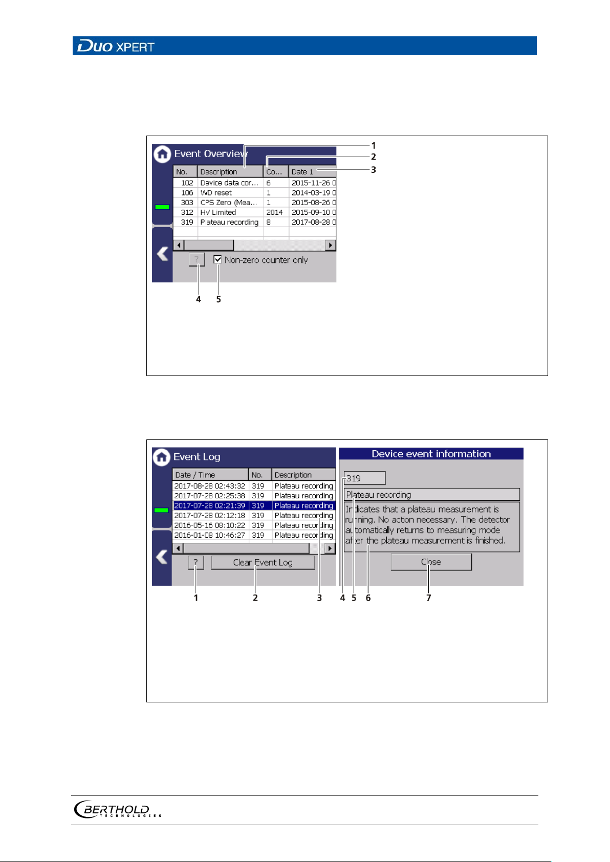
LB 470 Level 7 Main Menu Device Setup
97
1
2
3
4
5
Date / time of the event
Event no.
Info (event title)
Button <?> to display the detailed event description.
Button <Delete event log>
Fig.
1
2
3
4
5
6
7
Button <?>
Button <Clear event log>
Highlighted event
Event no.
Event title
Event description
Button <Close>
Fig.
Detector settings: Service | Event Log
Device settings | Setup | Sensors | [NAME DETECTOR] | Detector Service | Event Log
The last 25 events of the detector are displayed in the submenu "Event Log".
75 Event Log (Detector)
Display event description
76 Event Log
1. Click on a line in the list (Fig. 76, item 3).
2. Click on <? > (Fig. 76, item 1)
56925BA2 Rev. 03, 11/2017
The event description appears.
Page 98
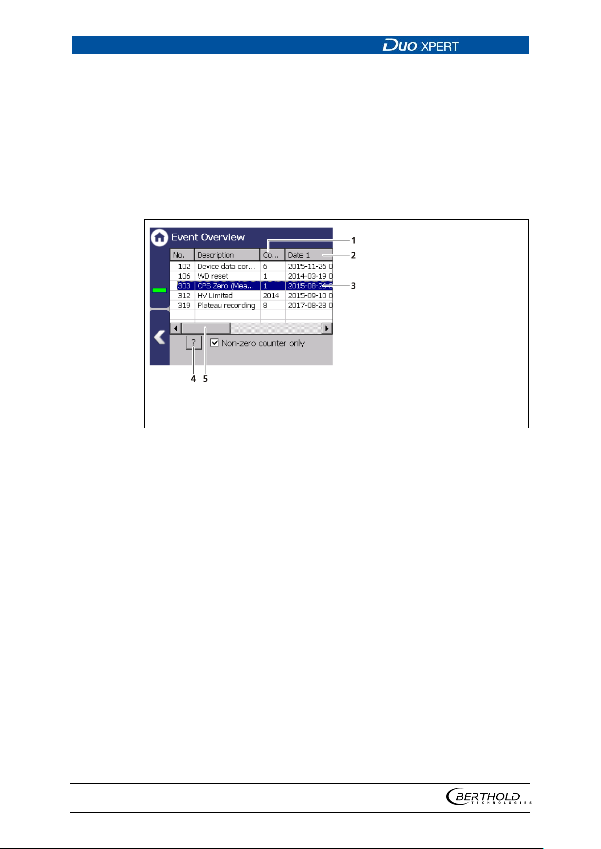
7 Main Menu Device Setup LB 470 Level
98
1
2
3
"Count" column
"Date" column
Event line
Button < ? >
Horizontal scroll barDisplay check box
"Non-zero counter only"
Fig.
3. With the button <Close>, close the event description (Fig. 76, item 7).
With the button <Clear event log> (Fig. 77, item 2) all events are deleted.
Detector settings: Detector Service | Event Overview
Device settings | Setup | Sensors | [NAME DETECTOR] | Detector Service | Event Overview
All events that can be logged are chronologically presented in tabular form in the
submenu "Event overview". Activate the check box "Non-zero counter only" in
order to display events that have occurred.
5
6
7
77 Event Overview
1. Click on a line in the list (Fig. 77, item 3).
2. Click on <? > (Fig. 77, item 4).
The event description appears.
3. With the button <Close>, close the event description.
4. Slide the bar of the horizontal scroll bar (Fig. 77, item 5) to the right to see at
what times (date, time) the event occurred.
The last 5 time points are displayed.
56925BA2 Rev. 03, 11/2017
Page 99
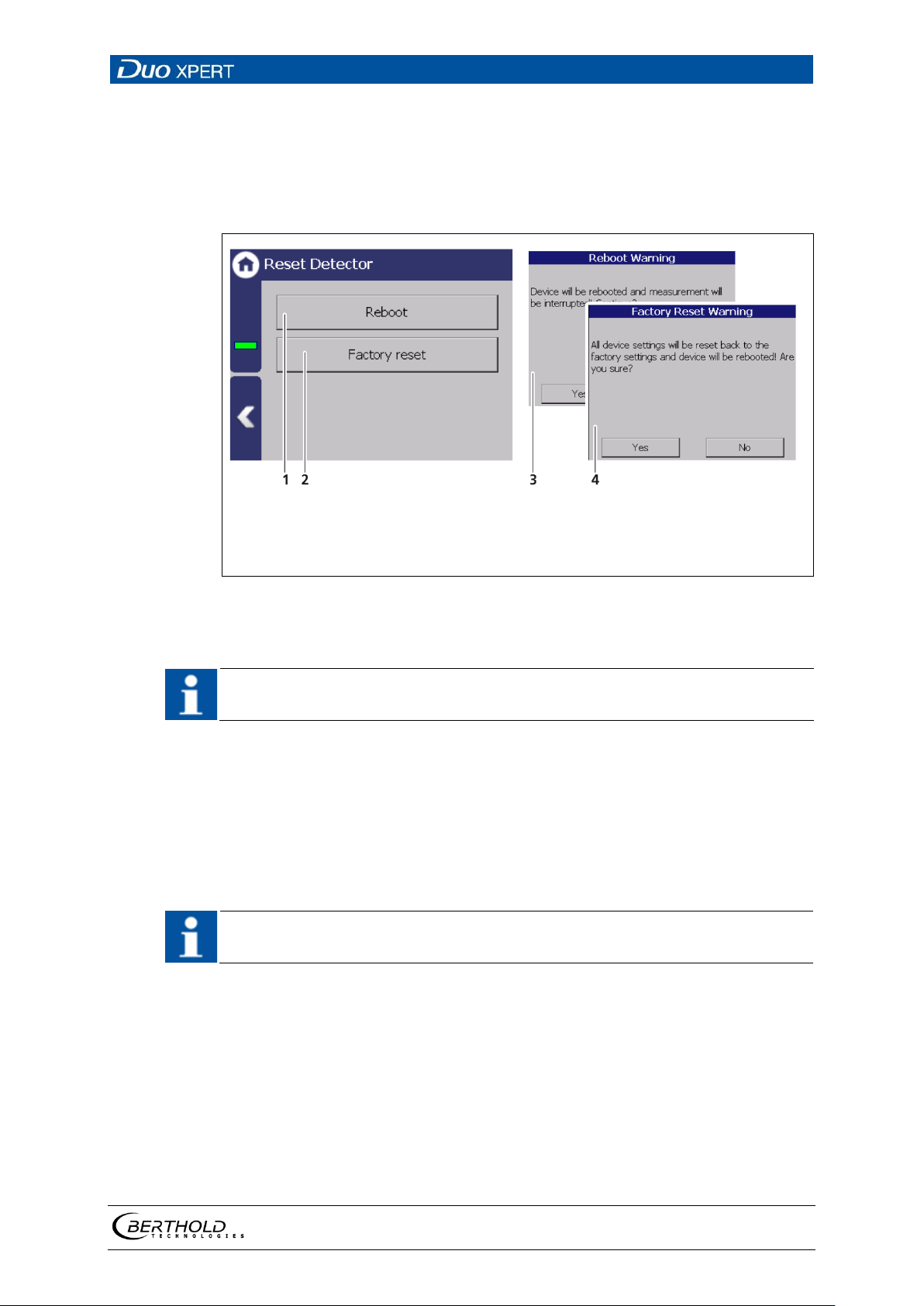
LB 470 Level 7 Main Menu Device Setup
99
1
2
3
4
Button Restart
Button Factory settings
Window "Warning: Reboot"
Window "Warning: Factory Reset"
Fig.
IMPORTANT
IMPORTANT
Detector settings: Detector Service | Reset Detector
Device settings | Setup | Sensors | [NAME DETECTOR] | Detector Service | Reset Detector
In the submenu ″Reset Detector″, the detector can be restarted and be reset to the
factory settings.
78 Reset Detector
The measurement is interrupted during a restart.
1. To restart the Detector, click the button <Reboot> (Fig. 78, item 1).
A window with a warning "Reboot" (Fig. 78, item 3) opens.
2. Click on <Yes> to confirm.
The device is restarted.
All custom configuration settings will be lost with a reset to factory settings!
1. To reset the detector to the factory settings, click the button <Factory reset>
Fig. 78, item 2).
(
A window with the warning Factory settings (Fig. 78, item 4) opens.
2. Click on <Yes> to confirm.
The device is reset to factory settings and restarts.
56925BA2 Rev. 03, 11/2017
Page 100
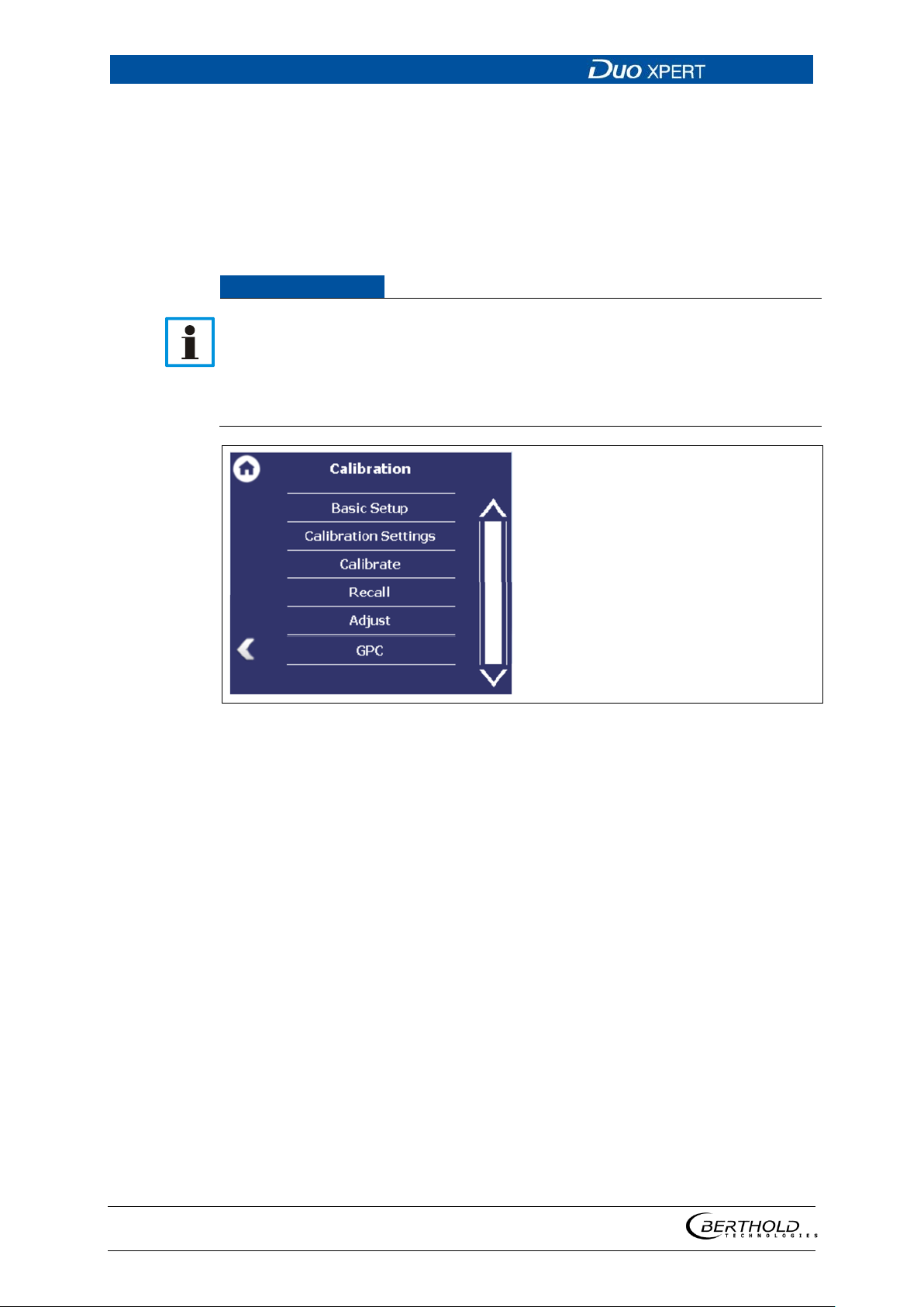
7 Main Menu Device Setup LB 470 Level
100
NOTICE
Material damage to the device or the system!
Fig.
7.3.3 92BCalibration
Device settings | Setup | Calibration
The Calibration menu is used for the selection of the calibration and calculation
method and for adaption of the measurement system to the respective environmental conditions, the actual radiation activity and the adaptation of the
background radiation (background level).
Errors in calibration or in the parameter setting can lead to incorrect measurement results. This may possibly lead to loss of production or to damage in the
system.
We encourage you to have the calibration and commissioning performed by
Berthold service.
79 Menu "Calibration"
56925BA2 Rev. 03, 11/2017
 Loading...