

Bertazzoni MAST486GDFS, PROF366DFSART, PROF486GDFSXT, MAST305DF, MAST365DFM Installation
...
BERTAZZONI
INSTALLATION MANUAL
FREESTANDING DUAL FUEL RANGES
3100293
WWW.BERTAZZONI.COM

/ Table of contents
TABLE OF CONTENTS
WARNINGS ___________________________________________________________________
DATA RATING LABEL ___________________________________________________________
BEFORE INSTALLATION ________________________________________________________
VENTILATION PREPARATION ____________________________________________________
SPECIFICATIONS ______________________________________________________________
CLEARENCE DIMENSIONS ______________________________________________________
INSTALLATION REQUIREMENTS _________________________________________________
Electrical ___________________________________________________________________
Gas ________________________________________________________________________
ELECTRICAL CONNECTION _____________________________________________________
WIRING DIAGRAM _____________________________________________________________
GAS CONNECTION _____________________________________________________________
Manual shut-off valve _________________________________________________________
Flexible connections __________________________________________________________
Pressure test-point stopper valve _______________________________________________
Pressure regulator ____________________________________________________________
INSTALLATION ________________________________________________________________
Unpackaging the range ________________________________________________________
Removing the oven door _______________________________________________________
Installing the legs _____________________________________________________________
Installing the worktop frontguard ________________________________________________
Installing the island trim _______________________________________________________
Installing backguard (optional) __________________________________________________
INSTALLING THE ANTI-TIP DEVICES ______________________________________________
Anti-tip brackets ______________________________________________________________
Anti-tilt chain ________________________________________________________________
GAS CONVERSION _____________________________________________________________
INSTALLATION CHECKLIST ______________________________________________________
FINAL PREPARATION ___________________________________________________________
BERTAZZONI SERVICE _________________________________________________________
4
5
6
7
7
9
10
10
10
10
12
14
14
14
14
15
16
16
16
17
17
18
18
19
19
19
20
22
22
23
2

/ Models
Models
MAST305DFMBIE
MAST305DFMNEE
MAST305DFMXE
MAST365DFMBIE
MAST365DFMNEE
MAST365DFMXE
MAST366DFSXT
MAST486GDFSXT
Models
PROF304DFSART
PROF304DFSBIT
PROF304DFSGIT
PROF304DFSNET
PROF304DFSROT
PROF304DFSXT
PROF366DFSART
PROF366DFSBIT
PROF366DFSGIT
PROF366DFSNET
PROF366DFSROT
PROF366DFSXT
PROF486GDFSART
PROF486GDFSBIT
PROF486GDFSGIT
PROF486GDFSNET
PROF486GDFSROT
PROF486GDFSXT
3
/ Warnings
WARNINGS
To ensure proper and safe operation, the appliance must be properly installed and grounded by a
qualifi ed technician. DO NOT attempt to adjust,
repair, service, or replace any part of your appliance unless it is specifi cally recommended in
this manual. All other servicing should be referred
to a qualifi ed servicer. Have the installer show you
the location of the gas shutoff valve and how to
shut it off in an emergency. A certifi ed technician
is required for any adjustments or conversions to
Natural or LP gas.
FOR THE INSTALLER: Before installing the Bertazzoni appliance, please read these instructions
carefully. This appliance shall be installed in accordance with the manufacturer’s installation instructions.
IMPORTANT: Leave these instructions with the
owner, who should save them for local inspector’s
use and for future reference. DO NOT remove
permanently affi xed labels, warnings, or plates
from product. This may void the warranty.
Installation must conform with all local codes. In
the absence of codes:
• United States: installation must conform with
the National Fuel Gas Code ANSI Z223.1
INFPA54
• Massachusetts: All gas products must be
installed by a “Massachusetts” licensed plumber or gasfi tter. A “T” type handle manual valve
must be installed in the gas supply line to the
appliance.
• Canada: Installation must be in accordance
with the current CAN/CGA B149.1 & 2 Gas
Installation codes and/or local codes. Electrical installation must be in accordance with the
current CSA C22.1 Canadian Electrical Codes
Part 1 and/or local codes.
This range is NOT designed for installation in
manufactured (mobile) homes or recreational
park trailers.
DO NOT install this range outdoors.
WARNING!
If the information in these instructions is not followed exactly, a fi re or explosion may result causing property damage, personal injury or death.
- Do not store or use gasoline or other fl ammable
vapors and liquid in the vicinity of this or any
other appliance.
- WHAT TO DO IF YOU SMELL GAS
•Do not try to light any appliance.
•Do not touch any electrical switch.
•Do not use any phone in your building.
•Immediately call your gas supplier from a
neghbor’s phone. Follow the gas supplier’s
instructions.
•If you cannot reach your gas suppliers, call
the fi re department.
- Installation and service must be performed by
a qualifi ed installer, service agency or the gas
supplier
DANGER!!! ELECTRIC SHOCK HAZARD!!!
To avoid risk of electrical shock, personal injury
or death, verify that the appliance has been properly grounded in accordance with local codes or
in absence of codes, with the National Electrical
Code (NEC). ANSI/NFPA 70- latest edition.
DANGER!!! GAS LEAK HAZARD!!!
To avoid risk of personal injury or death, leak-testing of the appliance must be conducted according to the manufacturer’s instructions. Before
placing appliance in operation, always check for
gas leaks with water and soap solution.
DO NOT USE AN OPEN FLAME TO
CHECK FOR GAS LEAKS.
This appliance must be properly grounded.
Grounding reduces the risk of electric shock by
providing a safe pathway for electric current in the
event of a short circuit.
Warning!
To avoid risk of property damage, personal
injury or death; follow information in this manual exactly to prevent a fi re or explosion.
4
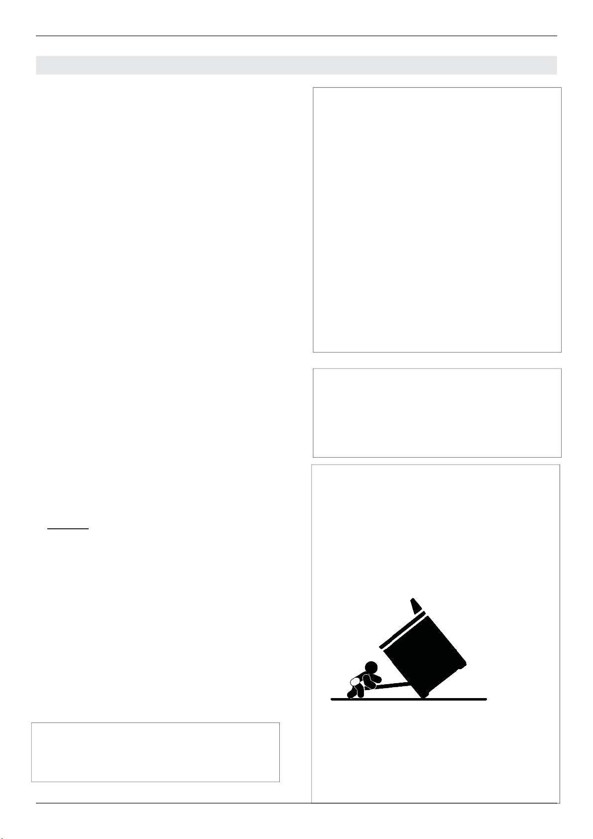
Warning - tipping hazard
A child or adult can tip over the range and be killed.
Install the anti-tip device to the structure and/or
the range. Verify the anti-tip device has been properly installed and engaged.
/ Warnings/ Data rating label
Engage the range to the anti-tip device by anti-tip
brackets or anti-tip chain (see installing the anti-tip device chapter). Ensure the anti-tip device is
re-engaged when the range is moved.
Re-engage the anti-tip device if the range is moved. Do not operate the range without te anti-tipdevice in place and engaged.
See anti-tip device installation instructions for
details.
Failure to do so can result in death or serious
burns to children or adults.
DO NOT lift the range by the oven door’s handle,
as this may damage the door hinges and cause
the door to fi t incorrectly.
DO NOT lift the appliance by the range’s control
panel.
The unit is heavy and should be handled accordingly. Proper safety equipment such as gloves
and adequate manpower of at least two people
must be used in moving the range to avoid injury
and to avoid damage to the unit or the fl oor.
Rings, watches, and any other loose items that
may damage the unit or otherwise might become
entangled with the unit should be removed.
Hidden surfaces may have sharp edges. Use caution when reaching behind or under appliance.
DO NOT use a hand truck or appliance dolly on
the back or front of the unit. Handle from the side
only.
DATA RATING LABEL
The data rating label shows the model and serial
number of the range. It is located under the control panel and in the last page of this manual
WARNING:
Cancer and Reproductiv Harm www.P65Warnings.ca.gov
.
5

/ Before installation
BEFORE INSTALLATION
• This appliance shall only be installed by an au-
thorized professional.
• This appliance shall be installed in accordance
with the manufacturer’s installation instructions.
• This appliance must be installed in accordance
with the norms & standards of the country where it will be installed.
• The installation of this appliance must conform
to local codes and ordinances. In the absence
of local codes, Installations must conforms to
American National Standards, National Fuel
Gas Code ANSI Z223.1 – latest edition/NFPA
54 or B149.1.
• The appliance, when installed, must be electri-
cally grounded in accordance with local codes
or, in the absence of local codes, with the National Electrical Code, ANSI/NFPA 70.
If local codes permit, a fl exible metal appliance
connection conduit with the new AGA or CGA certifi ed design, max. 5 feet (1,5 m) long, ½” I.D. is
recommended for connecting this appliance to the
gas supply line. Do not bend or damage the fl exible connector when moving the appliance.
This appliance must be used with the pressure
regulator provided.
The regulator shall be properly installed in order to
be accessible when the appliance is installed in its
fi nal location. The pressure regulator must be set
for the type of gas to be used. The pressure regulator has ½” female pipe thread. The appropriate
fi tting must be determined based on the size of
your gas supply line, the fl exible metal connector
and the shutoff valve.
The appliance must be isolated from the gas supply piping system by closing its individual manual
shutoff valve during any pressure testing of the
gas supply piping system at test pressures equal
to or less than 1/2 PSI (13,8” iwc or 3,5 kPa).
A manual valve shall be installed in an accessible
location in the gas line external to the appliance
for the purpose of turning on or shutting off gas to
the appliance.
Type of gas
This range can be used with Natural or LP/Propane gas. The range is shipped from the factory
for use with the gas indicated on the rating label
positioned on the lower face of the control panel
and in the last page of this manual. A step by step
conversion procedure is also included in this manual and in each conversion kit.
Gas pressure
The maximum inlet gas supply pressure incoming
to the gas appliance pressure regulator is 1/2 PSI
(13,8’’ iwc or 3,5 kPa). The minimum gas supply
pressure for checking the regulator setting shall
be at least 1“ iwc (249 Pa) above the inlet specifi ed manifold pressure to the appliance; this operating pressure is 4” iwc (1.00 kPa) for Natural
Gas and 10” iwc (2.50 kPa) for LP Gas.
Room ventilation
An exhaust fan may be used with the appliance;
in each case it shall be installed in conformity
with the appropriate national and local standards.
Exhaust hood operation may aff ect other vented
appliances; in each case it shall be installed in
conformity with the appropriate national and local
standards.
Warning
This appliance should not be installed with a
ventilation system that directs air in a downward
direction toward the range. This type of ventilation system may cause ignition and combustion
problems with the appliance resulting in personal
injury, property damage, or unintended operation.
Ventilating systems that direct the air upwards do
not have any restriction.
All opening and holes in the wall and fl oor, back
and under the appliance shall be sealed before
installation of the appliance.
6
Do not use aerosol sprays in the vicinity of
this appliance while it is in operation.
VENTILATION PREPARATION
/ Ventilation preparation / Specifi cations
This range will best perform when installed with
Bertazzoni exhaust hoods. These hoods have
been designed to work in conjunction with the
Bertazzoni range and have the same fi nish for a
perfect look.
Before installation of the exhaust hood, consult local or regional building and installation codes for
additional specifi c clearance requirements.
Refer to the range hood installation instructions
provided by the manufacturer for additional information.
Select Hood and Blower Models:
• For wall installations, the hood should be equal
or larger width than the range. Where space
permits, a hood larger than the range may be
desirable for improved ventilation performance.
• For island installations, the hood width should
overhang the range by a minimum of 3” (76
mm) on each side.
Hood Placement:
• For best removal of smoke and odors, the
lower edge of the hood should be installed
between 25 1/2” (65 cm) and 31 1/2” (80 cm)
above the range cooking surface.
• If the hood contains any combustible materials
(i.e. a wood covering), it must be installed at a
minimum of 36” (914 mm) above the cooking
surface.
Consider Make-Up Air:
Due to the high volume of ventilation air, a source of outside replacement air is recommended.
This is particularly important for tightly sealed
and insulated homes. A qualifi ed heating and
ventilating contractor should be consulted.
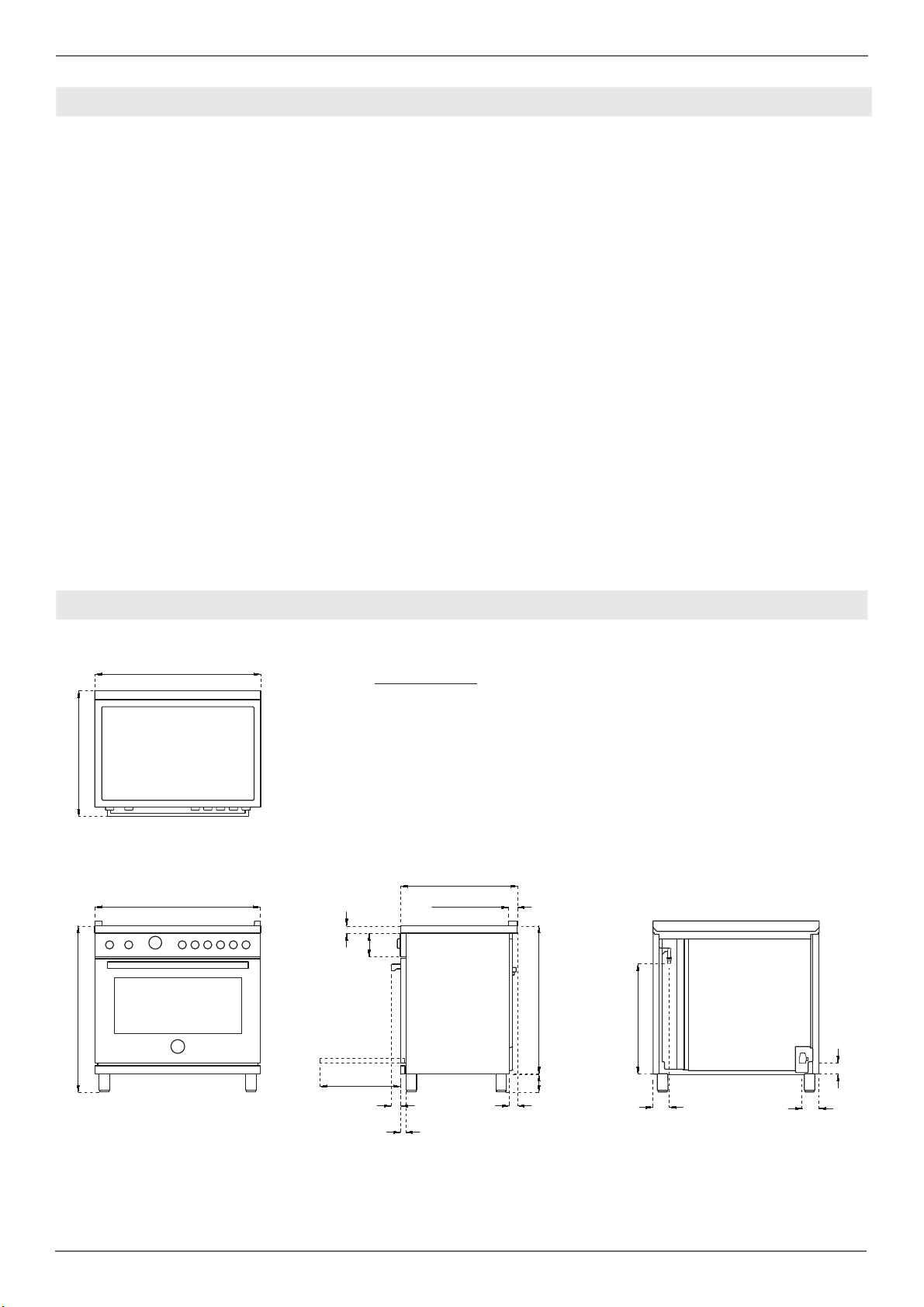
SPECIFICATIONS
A
/8
27''
A
MAX
1/2
37''
30’’ 36’’ 48’’
5/8
1''
5''
A
/16
25''
15/16
1''
32''
7/8
23''
''
/
2''
1/2
- 5''
3/4
5/8
1''
1/8
1''
3''
7/16
3''
3 ''
7/16
2''
11/16
7

/ Specifi cations
s
Burner
urner Injector
Injector
diam.[mm]
Auxiliary
0.90
0.54
Semi-rapid
1.18
0.70
Rapid
1.55
0.92
Dual burner
0.80+2.10
0.50+1.20
Gas
as
Type
NG
LP (Propane)
NG
LP (Propane)
NG
LP (Propane)
NG
LP (Propane)
Pressure
Pressure Max Rate Min Rate
[iwc]
4’’
10’’
4’’
10’’
4’’
10’’
4’’
10’’
Max Rate
[Btu/hr]
3,500
3,300
5,900
5,500
10,400
9,500
19000
19000
[W]
1,025
967
1,728
1,611
3,046
2,783
5,567
5,567
Min Rate
[Btu/hr]
900
900
1,500
1,500
2,500
2,500
1,300
1,300
[W]
264
264
439
439
732
732
381
381
By-pass
-pas
diam.[mm]
Regulated
0.29
Regulated
0.36
Regulated
0.47
Regulated
0.34/0.65
See use and care manual for the layout of the surface burners of your range
8

CLEARENCES DIMENSIONS
/ Clearence dimensions
Installation adjacent to kitchen cabinets
This range may be installed directly adjacent to
existing countertop high cabinets (36” or 91.5 cm
from the fl oor).
For the best look, the worktop should be level with
the cabinet countertop. This can be accomplished
by raising the unit using the adjustment spindles
on the legs.
ATTENTION: the range CANNOT be installed directly adjacent to kitchen walls, tall cabinets, tall
appliances, or other vertical surfaces above 36”
(91.4 cm) high. The minimum side clearance in
such cases is 6” (15.2 cm).
Wall cabinets with minimum side clearance must
be installed 18” (45.7 cm) above the countertop
with countertop height between 35 ½” (90.2 cm)
and 37 ¼” (94.6 cm). The maximum depth of wall
cabinets above the range shall be 13” (33.0 cm).
Cabinet
30’’ (76,2 cm)
A
36’’ (91,5 cm) hood with combustible materials
B
13’’ (33,0 cm)
C
18’’ (45,7 cm)
D
35’’ 1/2(90,2 cm) / 37”
E
F
6’ (15,2 cm)
1/4
(94,6 cm)
Metal hood
A
30’’ (76,2 cm)
B
25 1/2’’(65 cm) and 31 1/2’’ (80 cm)
C
13’’ (33,0 cm)
D
18’’ (45,7 cm)
E
35’’ 1/2(90,2 cm) / 37”
F
6’ (15,2 cm)
G
12”(30,50 cm)
H
1” 9/16(4 cm)
1/4
(94,6 cm)
B
G
H
D
F
B
A
C
E
/
If installing toekick, verify that the sum of the cutout areas equal the recommended ventilation (L)
30” area 40 sq. inches ( 25840 mm2)
36” area 51 ½ sq. inches ( 33107 mm2)
48” area 73 ½ sq.inches ( 47547 mm2)
Shaded area behind range indicates minimum
clearance to combustible surfaces, combustible
materials cannot be located within this area.
12” (305 mm) min. to combustible surface with
Flush Island Trim
For Flush Island installations, counter surface
should have a cantilever edge meeting the back
section of the Flush Island Trim accessory.
As defi ned in the “National Fuel Gas Code” (ANSI
Z223.1, Current Edition).
Clearances from non-combustible materials are
not part of the ANSI Z21.1
scope and are not certifi ed by CSA. Clearances of
less than 12” (305 mm)
must be approved by the local codes and/or by
the local authority having jurisdiction.
9

/ Installation requirements / Electrical connection
INSTALLATION REQUIREMENTS ELECTRICAL CONNECTION
ELECTRICAL
A properly-grounded horizontally- mounted electrical receptacle should be installed no higher than
3” (7.6 cm) above the fl oor, no less than 2” (5 cm)
and no more than 8” (20,3 cm) from the left side
(facing product).
Check all local code requirements.
GAS
An agency-approved, properly-sized manual
shut-off valve should be installed no higher than
3” (7.6 cm) above the fl oor and no less than 2” (5
cm) and no more than 8” (20.3 cm) from the right
side (facing product).
To connect gas between shut-off valve and regulator, use agency-approved, properly sized fl exible
or rigid pipe. Check all local code requirements.
Warning!
ELECTRICAL SHOCK HAZARD
Disconnect electrical power at the circuit breaker box or fuse box before installing the appliance.
Provide appropriate ground for the appliance.
Use copper conductors only.
Failure to follow these instructions could result in serious injury or death.
Warning!
Electrical grounding
This appliance is equipped with a three-prong
plug for your protection against shock hazard and
should be plugged directly into a properly grounded socket. Do not cut or remove the grounding
prong from this plug.
Caution
Label all wires prior to disconnecting when
servicing controls. Wiring errors can cause
improper and dangerous operation.
Verify proper operation after servicing.
installation area for the connection
The appliance shall be connected to a single phase electric line rated at 120/208Vac or 120/240Vac
and 60Hz frequency.
Type Voltage Circuit rating Electrical
supply
30” DFM 120/208V
120/240V
30” DFS 120/208V
120/240V
36” DFM 120/208V
120/240V
36” DFS 120/208V
120/240V
48” DFS 120/208V
120/240V
Install a suitable electric power supply receptacle
connection type NEMA 14-50R able to support a
load of at least 30 A (per line) according to local
code requirements. For four or three wires power
supply connection system see diagram below.
2900W 14A
3700W 16A
4300W 21A
5600W 24A
2900W 14A
3700W 16A
4500W 22,5A
5900W 25,5A
6800W 36,5A
8500W 40,5A
20A
20A
30A
30A
20A
20A
30A
30A
40A
40A
10

FOUR-WIRE CONN.RECEPTACLE NEMA 14-50R
THREE-WIRE CONN.RECEPTACLE NEMA 14-50R
/ Installation requirements / Electrical connection
The appliance is equipped at the factory with
an electric supply cord set 4 wires type with ring
terminals (L1, L2, N, Ground) suitable for range
use UL/CSA listed type SRDT/DRT 2x6AWG (L1,
L2)+2x8AWG (N, G) rated 300V, 40 or 50A with
fused plug type NEMA 14-50P; cable length 1,5
m.; in case the supply cord set must be replaced,
it shall be replaced with an identical set having the
same technical specs and following carefully the
instructions and diagrams below:
Check your local code for which of the options below should be used in grounding the receptacle
power supply connections.
OPTION 1 – FOUR Wires connection:
-Connect the L1 receptacle terminal to the incoming BLACK electrical supply wire (L1-hot wire)
-Connect the L2 receptacle terminal to the incoming RED electrical supply wire (L2-hot wire)
-Connect the NEUTRAL receptacle terminal to
the incoming NEUTRAL (WHITE) electrical supply wire
-Connect the GROUND receptacle terminal to the
incoming GROUND (GREEN) electrical supply
wire
OPTION 2 - THREE-Wires connection:
-Connect the L1 receptacle terminal to the incoming BLACK electrical supply wire (L1-hot wire)
-Connect the L2 receptacle terminal to the incoming RED electrical supply wire (L2-hot wire)
-Connect the NEUTRAL with the GROUND receptacle terminal to the incoming NEUTRAL (WHITE)
electrical supply wire
DO NOT USE EXTENSION CORDS WITH
THIS APPLIANCE AS IT MAY RESULT IN FIRE,
ELECTRIC SHOCK OR OTHER type of PERSONAL INJURY.
11

/ Wiring diagram
WIRING DIAGRAM
The electric wiring diagrams and schematics are attached behind the range, and should not be removed
except by a service technician, then replaced after service.
DFM
P2P1P8
P7
P3
P6
P2
P4
P5
P1
0
1
2
3
4
5
6
7
8
9
1
2
3
4
5
6
7
8
1
2
T
a
v
CMV
2
1
TSS
v
a
COLOURS
Simb. D escription
mBrown
rRed
gv G reen
vViolet
gr Grey
a O range
nBlack
bBlue
bi Whit e
RP
LEGENDA
Simb. Description
IGN Ignition Micro switches
COM Oven Function Selec tor
CMV Cooling fan air s ensor switc h
LF Oven lamp
M Terminal Bl ock
MV Fan motor
MVT Cooling fan mot or
RC Round elem ent
RC+RG Upper/gri ll element
RP Lower element
S Signal lights
TSS Safety Thermostat
T Thermost at
bi
a
MVT
RCRC
MV MV
IGN
G
n
bi
a
n
Commutatore.9+0
LF
r
LF
bi
P1
P2
P3
P4
P5
P6
P7
P8
P1
P2
COM
S
b
RG+RC
b
b
v
48 RIGHT SIDE
GE
r
S
m
n
RGR
m
gr
LEGENDA
a
bi
r
bi
L1 N L2
GROUND
n
n
LF
a
a
M
P1-2
P1-1
P1-3
P3-5
P2-4
0
1
2
3
4
COM
5
P3
5
2
P1
1
3
r
P2
g
4
a
b
b
a
a
bi
v
2
1
TSS
b
T
S
b
b
a
b
Simb. Description
C+T Swit ch + thermost at
GE Griddle Thermostat
2
1
TSS
bi
bi
LF Oven lamp
MTerminal Block
MVT Cooling fan motor
RC+RG Upper/grill element
RGR Griddle Element
RP Lower element
S Signal lights
TSS Safety Thermos tat
bi
MVT
12
RG+RC
RP
L1 N L2
GROUND
M
COLOURS
Simb. Description
mBrown
rRed
gv Green
vViolet
gr G rey
aOrange
nBlack
bBlue
bi White

30 /36 /48 DFS
nBlack
aOrange
gr Grey
vViolet
bi Whi te
bBlue
/ Wiring diagram
Simb. Descr iption
mBrown
gv Green
rRed
COLOURS
down
CMV
TS
to MV
to MV
MVMV
LF
up
PT
up
CMV
to CN23 - 3
to CN23 - 2
to CN23 - 1
to CN23 - 3
to CN23 - 2
to CN23 - 1
to CN1 - 1
to CN1 - 2
to CN1 - 3
to CN1 - 4
to CN1 - 5
to CN1 - 6
EG
FS
A
MT
MVT
B
b
n
bi
a
CN30
1.3
CN23
1.3
CN24
CN21
1..4
CN2
CN1- 1....6
a
RCRC
to MV
v
r
b
v
RP
b
CN22 -3.1
CN27 - 6.....1
CN28 - 6.....1
gr
gr
to M-GROUND
to MV
bi
to M-L1
to M-L1
to DL
to DL
to M-N
RG+RC
a
to DL
to DL
LF
MVT
down
GROUND
M
L1 N L2
bi
to RP
to M-L1
to M-N
to GROUND
n
K
n
G
IGN
bi
1
bi
2
n
n
n
n
to M-L1
to M-L1
to M-L1
DL
to CN26 - 3
to CN27 - 6
to CN26 - 2
to CN27 - 5
to M-L1
r
r
TSS
RC+RG Upper/gri ll elem ent
bi
n
MVT Cool ing fan motor
MV Fan motor
RC Round element
PT Oven sensor Temp. (PT1000)
MT Meat Probe
LF Oven lamp
MTerminal Block
IGN Ignit ion Micro switches
TS Oven Temperature Selecton
K Termal cut out
EG Electronic Gauge
DL Door Lo ck - Door Switc h
FS Oven Function S elector
G S park Generat or
Simb. Description
CMV Cooling fan air sensor switch
B Thermal cut-out
LEGENDA
n
r
B
13

/ Gas connection
GAS CONNECTION
Warning!
DO NOT USE AN OPEN FLAME WHEN
CHECKING FOR LEAKS!
Leak testing of the appliance shall be conducted
according to the manufacturer’s instructions. Before placing the oven into operation, always check
for leaks with soapy water solution or other acceptable method.
Check for gas leakage with soapy water solution or
other acceptable methods in all gas connections
installed between inlet gas pipe of the appliance,
gas regulator, till to the manual shut-off valve.
All gas connections must comply with national and
local codes. The gas supply line (service) must be
the same size or greater than the inlet line of the
appliance. This range uses a 1/2” NPT inlet (see
drawing below for details of gas connection). On
all pipe joints use appropriate sealant resistant to
gas to joint the adapter to range manifold use only
the blue gasket supplied.
If necessary, the appliance must be converted by
the dealer, by a factory-trained professional or by
a qualifi ed licensed plumber or gas service company.
FLEXIBLE CONNECTIONS
In case of installation with fl exible couplings and/
or quick-disconnect fi ttings, the installer must use
a heavy-duty, AGA design-certifi ed commercial
fl exible connector of at least 1/2” (1.3 cm) ID NPT
(with suitable strain reliefs) in compliance with
ANSI Z21.41 and Z21.69 standards.
In Massachusetts: The unit must be installed
with a 36” (3-foot) long fl exible gas connector.
In Canada: use CAN 1-6.10-88 metal connec-
tors for gas appliances and CAN 1-6.9 M79 quick
disconnect device for use with gas fuel.
PRESSURE TEST-POINT STOPPER
VALVE
To avoid gas leaks, the pressure test-point stopper valve and gasket supplied with the range must
be installed on the gas fi tting at the back of the
range according to the diagram below.
Gas conversion is important for safe and eff ective use of the appliance. It is the responsibility of
the dealer and the owner of the range to perform
the appropriate gas conversion following the directions of the manufacturer.
THE GAS CONVERSION PROCEDURE IS
DESCRIBED IN THIS MANUAL AND IN THE
PACKAGE CONTAINING THE CONVERSION
NOZZLES SHIPPED WITH EVERY RANGE.
Please provide the service person with this manual before work is started on the range.
MANUAL SHUT-OFF VALVE
THIS VALVE IS NOT SHIPPED WITH THE APPLIANC AND MUST BE SUPPLIED BY THE INSTALLER.
The manual shut-off valve must be installed in the
gas service line between the gas hook-up on the
wall and the appliance inlet, in a position where it
can be reached quickly in the event of an emergency.
GAS PIPE
GASKET
GAS CONNECTION ADAPTOR
1/2’’NPT WITH PRESSURE TEST
POINT 1/8’’ NPT (TO BE FIXED
TOWARD EXTERNAL SIDE OF
THE APPLIANCE)
PRESSURE TEST-POINT
STOPPER
In Massachusetts: A ‘T’ handle type manual
gas valve must be installed in the gas supply line
to this appliance.
14

PRESSURE REGULATOR
Since service pressure may fl uctuate with local
demand, every gas cooking appliance must be
equipped with a pressure regulator on the incoming service line for safe and effi cient operation.
The pressure regulator shipped with the appliance has two female threads ½” NPT. The regulator
shall be installed properly in order to be accessible
when the appliance is installed in its fi nal position.
/ Gas connection
Manifold pressure should be checked with a manometer and comply with the values indicated below:
Natural gas 4.0” iwc.
LP/Propane 10.0” iwc.
Incoming line pressure upstream from the regulator must be 1” iwc. higher than the manifold pressure in order to check the regulator.
The regulator used on this range can withstand a
maximum input pressure of 1/2 PSI (13,8” w.c. or
3,5 kPa) If the line pressure exceeds that amount,
a stepdown regulator is required.
The appliance, its individual shut-off valve, and
the pressure regulator must be disconnected from
the gas line during any pressure testing of that system at pressures in excess of 1/2 PSI (13,8” iwc
or 3,5 kPa).
The individuaL manual shut-off valve must be in
the OFF position during any pressure testing of
the gas supply piping system at test pressures
equal to or less than 1/2 PSI (13,8” iwc or 3,5 kPa).
Warning
Before carrying out any servicing operation disconnect the appliance from gas and electric
supply and extra appliance from fi nal installation
place in order to have access to the appliance for
proper servicing intervention.
15

/ Installation
INSTALLATION
APPLIANCE INSTALLATION
Unpacking the range
• Remove all packing materials from the ship-
ping pallet but leave the adhesive-backed foam
layer over brushed-metal surfaces to protect it
from scratches until the range is installed in its
fi nalposition. Only the fi lm on the side panels
should be removed before inserting the range
between the cabinets.
• Examine the appliance after unpacking it. In the
event of transport damage, do not plug it. Take
pictures of the damage and report it immediately to the freight forwarder.
• Remove the oven door(s). This will reduce the
weight of the range.
• The grates, griddle plate, burner caps, and oven
racks should be removed to facilitate handling.
• Before moving the range, protect the fl oor to
prevent damage.
REMOVING THE OVEN DOOR
Prepare the door for removal. Flip up the locking
clamps on each door hinge. Slowly shut the door
until the protruding clamps stop the movement.
Pull oven door upwards and remove.
Do not lift or carry the oven door by its handle!
This may damage the hinges.
1
2
16
3

/ Installation
INSTALLING THE LEGS
Bertazzoni ranges must be used only with the legs
properly installed.
Four height-adjustable legs are supplied with the
range in the polysterene container situated over
the appliance.
Before installing the legs, position the appliance
near its fi nal location as the legs are not suitable
for moving the appliance over long distances.
After unpacking the range, raise it enough to insert the legs in the appropriate receptacles situated on the lower part of the appliance. Lower the
range gently to keep any undue strain from legs
and mounting hardware. If possible use a pallet or
lift jack instead of tilting the unit.
Adjust leg height to the desired level by twisting
the inside portion of the leg assembly until the proper height is reached. Check with a level that the
cooktop is perfectly level.
INSTALLING THE WORKTOP
FRONTGUARD
To increase the clearance between the front edge
of the worktop and the burners, it is possible to
install a front guard for the worktop.
To install the front guard,
• Locate the two fi xing holes on the end of the
front guard.
• Locate the two fi xing holes on the bottom facet
of the worktop
• Fix the front guard with it’s two screws
1
2
3
4
17

/ Installation
INSTALLING THE ISLAND TRIM
The island trim must be installed prior to operation
of the appliance for appropriate ventilation of the
oven compartment.
The island trim is only placed on the cooktop, remove all tape and packaging before installing it.
INSTALLING BACKGUARD (OPTIONAL)
The backguard must be installed prior to operation of the appliance for appropriate ventilation of
the oven compartment.
The backguard is an optional contact you dealer
for buying it.
1 1
2 2
3
3
4 4
18

INSTALLING THE ANTI/TIP DEVICES
/ Installing the anti/tip devices
ANTI-TIP BRACKETS
The anti-tip bracket shipped with the range must
be properly secured to the rear wall as shown in
the picture below.
The height of the bracket from the fl oor must be
determined after the range legs have been adjusted to the desired height and after the range has
been levelled.
• Measure the distance from the fl oor to the
bottom of the anti-tip bracket receptacle on the
back of the appliance.
• Position the anti-tip brackets on the wall at
the desired height plus 1/8” (0.32 cm). The
brackets must be placed at 2”5/16 (6,0 cm)
from the side of the range.
• Secure the brackets to the wall with appropria-
te hardware.
• Slide the range against the wall until the
brackets are fully inserted into their receptacles on the back of the range.
ANTI/TILT CHAIN
The anti-tilt chain shall be installed on right or left
side alternatively according below instructions.
The chain shall be hand pulled and fi xed to open
hook through closed ring.
Disengage the chain prior to moving the appliance
for service.
Attention:
Once servicing operation have been completed
the anti-tilt devices ( brackets and chain) shall be
re-engaged according above instruction/installations.
1
CLOSED RING OPEN HOCK
2
19

/ Gas conversion
GAS CONVERSION
Warning!
Before carrying out this operation, disconnect the
appliance from gas and electricity.
Gas conversion shall be conducted by a factory-trained professional.
Call the customer service hotline to identify a fac-
tory-trained professional near your home.
The gas conversion procedure for this range includes 6 steps:
• Pressure regulator
• Surface burners
• Oven burner
• Broiler burner
• Visual checks prior to closure of oven bottom
panel
• Adjustment of minimum setting
LP
The conversion is not completed if all 6 steps have
not been concluded properly.
Before performing the gas conversion, locate the
package containing the replacement nozzle shipped with every range.
IMPORTANT: Each nozzle has a number indicating its fl ow diameter printed on the body. Consult
the table number 1 for matching nozzles to burners.
Save the nozzles removed from the range for future use.
Step 1: pressure regulator
The pressure regulator supplied with the appliance is a convertible type pressure regulator for use
with Natural Gas at a nominal outlet pressure of
4” w.c. or LP gas at a nominal outlet pressure of
11” w.c. and it is pre-arranged from the factory to
operate with one of these gas/pressure as indicated in the labels affi xed on the appliance, package
and Instruction booklet.
To convert the regulator for use with the other gas:
Unscrew by hand the upper cap of the regulator, remove the white plastic attachment from the
cap, reverse its direction and screw it again fi rmly against the cap. The white plastic attachment
has arrows indicating the position for natural gas
(NAT) and LP gas (LP).
Screw by hand the metal cap in the original position on the regulator.
NAT
Step 2: surface burners
To replace the nozzles of the surface burners, lift
up the burners and unscrew the nozzles shipped
with the range using a 7 mm (sochet wrench).
Replace nozzles using the conversion set supplied with the range or by a Bertazzoni authorized parts warehouse. Each nozzle has a number
indicating its fl ow diameter printed on the body.
Consult the table number 1 and matching nozzles
to burners.
20
Step 3: visual checks
Surface burners
The burner fl ame color should be blue with no yellow on the tips. It is not uncommon to see orange
in the
fl ame color; this indicates the burning of airborne
impurities in the gas and will disappear with use.
With propane (LP) gas, slight yellow tips on the
primary icone are normal.
The fl ame should burn completely around the burner cap. If it doesn’t, check that the cap is positioned
correctly on the base and that the ports are not
blocked.
The fl ame should be stable with no excessive noise or fl uttering.
/ Gas conversion
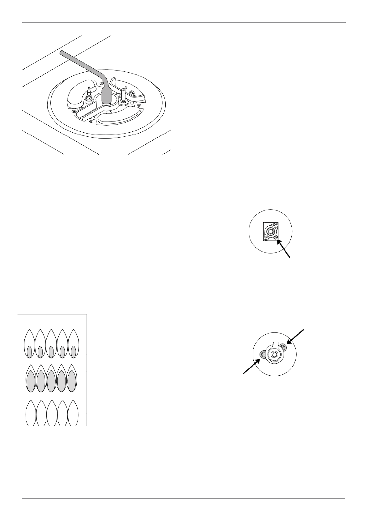
Step 4: minimum fl ame adjustment
WARNING!
These adjustments should be made only for use
of the appliance with natural gas. For use with liquid propane gas, the choke screw must be fully
turned in a clockwise direction.
SURFACE BURNERS
Light one burner at a time and set the knob to the
MINIMUM position (small fl ame).
Remove the knob.
The range is equipped with a safety valve. Using
a small-size slotted screwdriver, locate the choke
valve on the valve body and turn the choke screw
to the right or left until the burner fl ame is adjusted
to desired minimum.
Make sure that the fl ame does not go out when
switching quickly from the MAXIMUM to the MINIMUM position.
For the gas valve of dual burner the choke valve
is located on the valve body (fi g.20), the A screw
adjust the outer ring, the B screw adjust the inner
ring.
yellow fl ames:
further adjustment is required
yellow tips on outer cones:
normal for LP gas
soft blue fl ames:
normal for natural gas
After performing all these visual checks, reinstall
the bottom panel of the oven compartment and
proceed to setting the minimum for each burner.
B
A
21

/ Installation checklist / fi nal preparation
INSTALLATION CHECKLIST FINAL PREPARATION
A qualifi ed installer should carry out the following
checks:
Range mounted on its legs
Island trim or Backguard attached according to instruction
Anti-tip device properly installed
Clearance to cabinet surfaces as manufacturer’s guideline
Proper ground connection
Gas service line connected following manufacturer’s guideline
Valves, stoppers and gasket installed
between the range and the service line
Gas connection tested and free of gas
leaks
Range settled for the type of gas available
in the household
Each burner lights satisfactorily, both individually and with other burners operating
Flame appear sharp blue, with no yellow
tipping, shooting or fl ame lifting
Minimum settled for all burners
Oven light works properly
• Before using the oven, remove any protective
wrap from the stainless steel.
• All stainless steel body parts should be wiped
with hot, soapy water and with a liquid stainless
steel cleanser.
• If buildup occurs, do not use steel wool, abrasi-
ve cloths, cleaners, or powders!
• If it is necessary to scrape stainless steel to re-
move encrusted materials, soak with hot, wet
cloths to loosen the material, then use a wood
or nylon scraper.
• Do not use a metal knife, spatula, or any other
metal tool to scrape stainless steel! Scratches
are almost impossible to remove.
• Before using the oven for food preparation,
wash the cavity thoroughly with a warm soap
and water solution to remove fi lm residues and
any dust or debris from installation, then rinse
and wiped dry.
Attention!
When using the oven for the fi rst time it
should be operated for 15-30 minutes at a temperature of about 500°F/260°C (main oven) or
440°F/227°C(auxiliary oven) without cooking
anything inside in order to eliminate any moisture and odours from the internal insulation.
22

BERTAZZONI SERVICE
Bertazzoni is committed to providing the best customer and product service. We have a dedicated
team of trained professionals to answer your needs.
If you own a Bertazzoni appliance and need service in the US or Canada please use the following
contact information:
e-mail: aftersaleservice@bertazzoni.com
Telephone - Monday through Friday,
7.30am to 7.30pm EST (except US public holidays).
US 866-905-0010
WESTERN CANADA 866-905-0010 (BC,AB,SK,MB)
EASTERN CANADA 800-561-7265 (ON,QC,NL,NB,NS,PE)
/ Bertazzoni service
23
 Loading...