


Sensor-Line S 401

Instruction manual
Sensor-Line S 401
Please keep this manual in a safe place.
S 401 GB - 1 - 03-06
G
B
B 190.028-GB

S 401 GB - 2 - 03-06
Index
1.0 Technical Data .................................................................................................... 3
2.0 General Instructions........................................................................................... 4
2.1 General safety instructions................................................................................ 4
2.2 Designated use................................................................................................. 4
2.3 Indication for operating...................................................................................... 4
3.0 Drive assembly ................................................................................................... 6
3.1 Scope of supply................................................................................................. 6
3.2 Required tools ..................................................................................................... 6
3.3 Installation requirements....................................................................................... 6
3.4 Assembly ............................................................................................................ 7
3.5 Installation......................................................................................................... 9
3.6 Initial operation................................................................................................ 13
3.6.1 Insert red/green light module.................................................................... 13
3.6.2 Functions and connections....................................................................... 14
3.6.3 Set-Up...................................................................................................... 15
3.6.3.1 Adjustment of force and travel ........................................................................15
3.6.3.2 Individual adjustments.....................................................................................15
3.6.4 Perform safety check................................................................................ 18
3.6.5 Warning notices........................................................................................ 18
3.6.6 Radio........................................................................................................ 18
3.6.6.1 Installation of the radio....................................................................................18
3.6.6.2 Set-Up of the radio.........................................................................................18
3.6.6.3 Testing the radio .............................................................................................18
4.0 Maintenance...................................................................................................... 19
5.0 Demounting and disposal................................................................................ 19
6.0 Failure analysis................................................................................................. 20
7.0 Operating Instructions radio system PICO, 868,5 MHz................................. 21
8.0 TÜV-Certificate.................................................................................................. 22
9.0 TÜV-Doors......................................................................................................... 22
10.0 EC-Manufacturer's Declaration ..................................................................... 23
11.0 EC- Manufacturer’s Declaration according to EC Directive........................ 24
12.0 Handing over................................................................................................... 24

S 401 GB - 3 - 03-06
1.0 Technical Data
Description S 401-60 S 401-80 S 401-100 S 401-120
standard circuit
board
B 300.01
head
variations
optional red /
green light mod-
ule (red / green
light red/ green,
230VAC, 50Hz,
1A)
B 300.04
electric supply 230 V / 50 Hz
temporary peak load max. 600 N max. 800 N max. 1000 N max. 1200 N
motor voltage
circuit board voltage
0 – 24 VDC
motor power max. 110 W max. 120 W max. 150 W max. 180 W
tractive- /pressure power max. 600 N max. 800 N max. 1000 N max. 1200 N
switch-on-time 30%
speed (without load) max. 14cm/sec
lighting 40W/230V (E14)
duration of lighting 30-180 sec
Radio (standard delivery) 868,5 MHz
ambient temperature -20°C/ +40°C
idle running – power loss < 1 W
fusible cut-out
F1:3,15AT/250V
F2:6,3AT/250V
F1:3,15AT/250V
F2:6,3AT/250V
F1:3,15AT/250V
F2:10AT/250V
F1:3,15AT/250V
F2:10 AT/250V
minimum mounting height 35 mm
overall drive length 3,31 m
head height 145 mm
ca. weight (with 3,00m rail) ca. 18 kg
travel path (with 3,00m rail) 2,40 m (with extension up to 5,4 m possible)
max. area of door (smooth
running, good balanced doors)
8 m² 10 m² 12 m² 14 m²

S 401 GB - 4 - 03-06
2.0 General Instructions
This instruction manual is being released by
BERNAL without any warranty.
BERNAL reserves the right to make changes
or modifications on the equipment at any time
and on this manual without giving any prior
notes.
2.1 General safety instructions
Important Safety Instructions:
Qualified personnel should only
perform the assembly and installa-
tion of the garage door opener.
Faulty installation may lead to serious injuries! Disconnect power plug before any
work on the device is done. (except on test
and learning procedures) !
On installation the relevant regulations for the operational safety act
/ employers mutual insurance association have to be followed, e.g. UVV, DIN
EN 60335-1 and VBG4.
The electro installation has to be
performed by a qualified electri-
cian, and has to conform to the
relevant industrial safety regulations, according to DIN VDE 0100 and DIN VDE 0113.
The power point must be easily accessible
and at a max. distance of 50cm from the
opener head.
Do not operate the garage door
opener at all, until it is confirmed,
that the garage door is in accordance with the safety norm 98/37/EG and a
valid EC-Declaration of Conformity certificate is issued.
.
An improper installation or any change to the
opener without the manufacturers previous
approval, any warranty or product liability is
null and void. The installation has to be performed in accordance with this instruction. The
installation of foreign elements endangers the
safe operation of the opener and is not permitted.
You have to pay attention that the relevant national VDE-regulations for operating electrical
appliances are strictly adhered to.
We do not take any responsibility for the improper operating or maintenance of the door,
accessories and the opener.
2.2 Designated use
The garage door opener is designed only for
the operation with well-balanced swing- and
sectional doors in the non-commercial sector.
The recommended max. door measurements
are listed under 1. Technical Data. The door
has to be in accordance with the valid specifications (e.g. DIN EN 12604 and DIN EN
12605). Before mounting the opener, check
that the door can to be easily moved by hand.
FOR THE SAFETY AND LIFE OF PERSONS IT IS ABSOLUTELY NECESSAR
Y
TO FOLLOW ALL INSTRUCTIONS.
KEEP THESE INSTRUCTIONS
The opener is designed for the operation in dry
rooms.
The garage ceiling has to be constructed, so
that a safe attachment of the opener is assured.
2.3 Indication for operating
For garages without a second entrance, a
emergency release is necessary. A function
test of the emergency release has to be carried out monthly!
Do not hang on the cord of the emergency release with your weight!
Make sure, that the emergency release of the
opener does not collide with the roof rack or
any protrusions of the vehicle or the door.
Instruct all persons, who are using the garage door and opener, about a safe and
proper handling. Demonstrate and test the
reversion (with a 50 mm high obstacle at
max. 150 N) as well as the mechanical
unlocking.
Operate the door only, when you can see
the whole door area unobstructed. Pay attention, that there are no persons or any
objects in the door operating area.
Wait until the door stands still. Persons or
vehicles are only allowed in door operating
area, when the door is completely open and
at standstill.

S 401 GB - 5 - 03-06
oor, opener and extra installed safety ac-
ttention:
an shut down faster with weak,
hen service- or adjustment work is ur-
Do not permit children to
play with the automated garage door. Transmitters are
to be kept safe and away
from children !
Fixed accessories (like key switch or similar) have to be attached in sight of the door.
The accessory distance to the moving parts
of the door, and at a minimum mounting
height of 1,80m. Accessories have to be installed beyond the reach of children! Alert
stickers against pen in have to be put close
to the fixed key switch.
D
cessories have to be checked regularly.
See chapter 4 maintenance.
A
The door c
broken or damaged springs or a defective
counterweight. Under this circumstances
using the emergency release may lead to
uncontrolled movements of the door.
W
gently required, do not use the opener . A
badly balanced door, or a faulty garage
door drive may cause damage and injuries.
S 401 GB - 6 - 03-06
3.0 Drive assembly
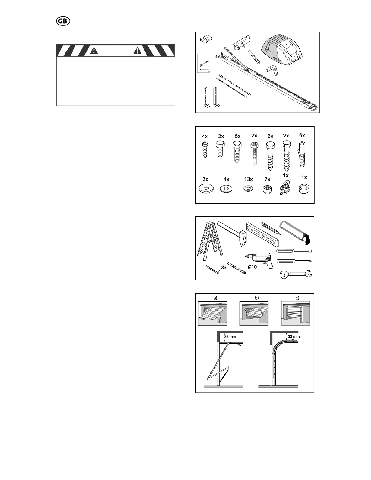
3.1 Scope of supply
The scope of supply, as shown on the Fig. 1
and 2, may vary according to the drive version.
3.2 Required tools
For the assembly und mounting of the drive
the tools shown in Fig. 3 are required (not in
the scope of supply).
3.3 Installation requirements
The garage door opener is suitable for the
automation of spring balanced swing doors
(Fig. 4a) and sectional door (Fig. 4c).
(max. sizes see 1.0 technical data).
For an optimal attachment of the push rod to
the sectional door, a sectional door attachment
is available as an accessory.
For doors, that are non-protruding up-andover, a curved arm is available as accessory.
(Fig. 4b)
For the mounting a minimum lintel height of 35
mm is necessary (Fig. 4).
Fig.1
CAUTION
IMPORTANT INSTRUCTIONS FOR A
SAFE MOUNTING
ATTENTION – INCORRECT MOUNTING
MAY LEAD TO SERIOUS INJURY – ALL
MOUNTING INSTRUCTIONS HAVE TO
BE FOLLOWED
Fig. 2
Fig. 3
Fig. 4
3.4 Assembly
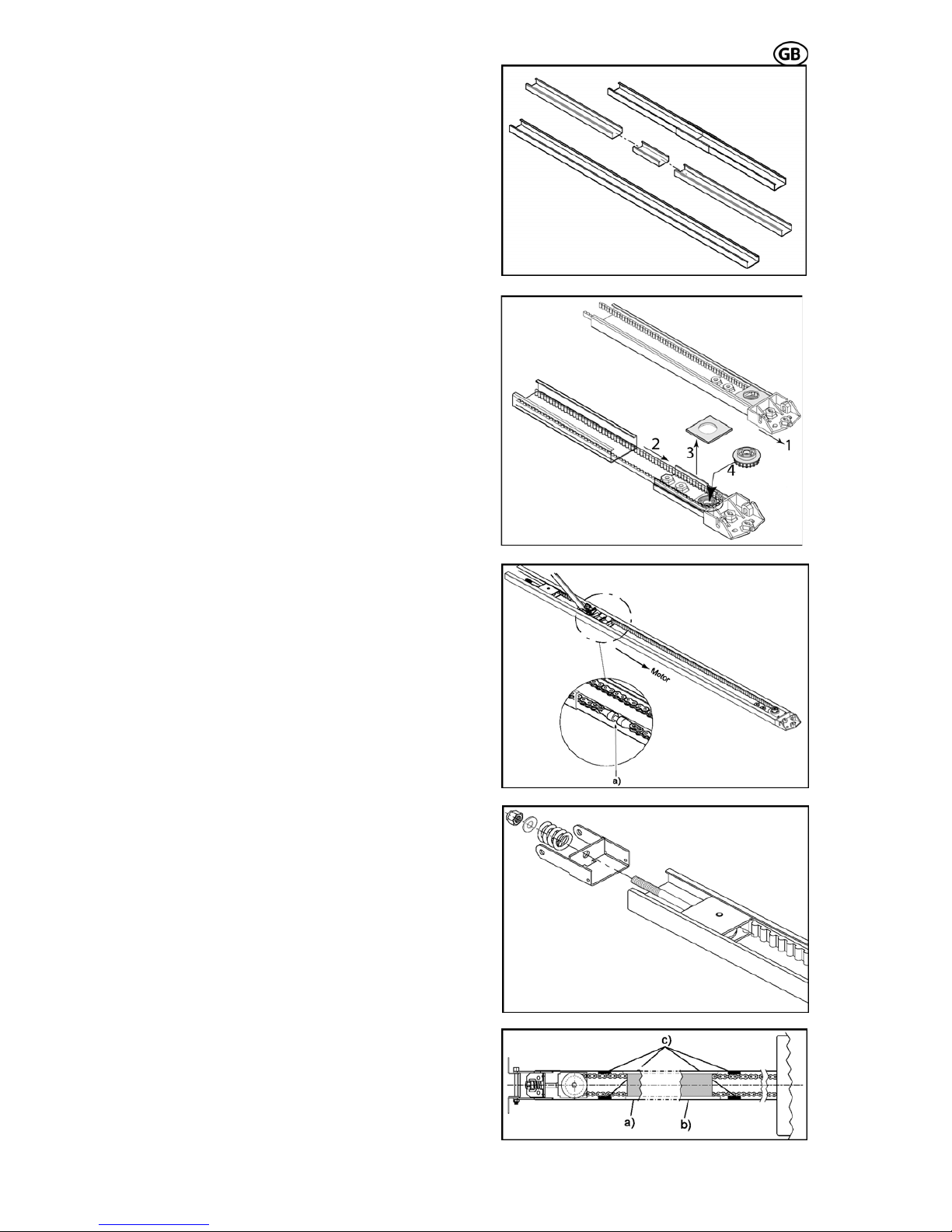
Pre-assembly of rail
According to the version, the rails have to be
pre-mounted as requirements.
Put the rails together via the connection rail.
(Fig. 5) Slide the rails together to the stop position.
Pull the rear bracket (Fig. 6.1) together with the
belt (Fig. 6.2) out of the rail. Remove the
transportation covering (Fig. 6.3) and press the
pinion (Fig. 6.4) into the bearing. Take care of
the belt not being squeezed. Then attach the
transportation covering again and push the
complete rear bracket back into the rail.
S 401 GB - 7 - 03-06
Adjust the tension of the chain or belt by pulling the idler wheel towards the chain end.
Make sure, that the chain lock (Fig. 7a) is on
the left side of the rail. (Fig. 7)
Then push the tensioning bracket towards the
end of the chain and guide the coach bolt
through the hole of the tensioning bracket. Pay
attention that the coach bolt fits into the tensioning bracket.
Push the provided spring and washer on the
end of the coach bolt and screw the nut on the
coach bolt. (Fig. 8)
Paste rubber buffers
If you have a chain drive, we recommend sticking the provided rubber buffers to the inside of
the rail (Fig. 9c). Those serve to minimize the
noise caused, when the chain touches the rail.
Assure, that the rubber buffers are not in the
travel path of the trolley. The buffers have to
be put close to the end of the chain, so that the
trolley doesn’t touch them in door-closed- (Fig.
9a) or in door-open-position (Fig. 9b).
Fig. 5
Fig. 6
Fig. 7
Fig. 8
Fig. 9

S 401 GB - 8 - 03-06
S 401 GB - 8 - 03-06
sion chain / belt
Turn the nut to tension the chain or belt
slightly. Fig. 10).
Trolley test
Check afterwards, that the trolley can easily be
moved by hand. To release the trolley, from
the chain lock, pushes the lever on the trolley
and at the same time move the trolley in the
rail (Fig. 11).
Make absolutely sure, that after this test the
trolley engages on the chain lock. To perform
this, move the trolley without holding the lever
over the chain/belt lock and the trolley engages automatically.
Assembly of door bracket
According to the installation situation the provided push rod components can be combined
as needed (Fig. 12).
If the length of the push rod is not sufficient, it
can be adjusted via the extension rod (Fig.
12a). In adoption with sectional doors, we recommend the use of a sectional door angle
(Fig. 12c). Then the provided door bracket
(Fig. 12b) has to be attached to the push rod.
For the assembly use the provided screws,
washers and nuts, and tighten them firmly.
Fig. 10
Pre-ten
Fig. 11
Fig. 12
 Loading...