

Page 1
Radio Module installation guide
The Aurora miniRITE 312 T Rc radio model contains two radio transceivers running at 3.84 MHz and 2.4 GHz and both implemented on a single hardware platform.
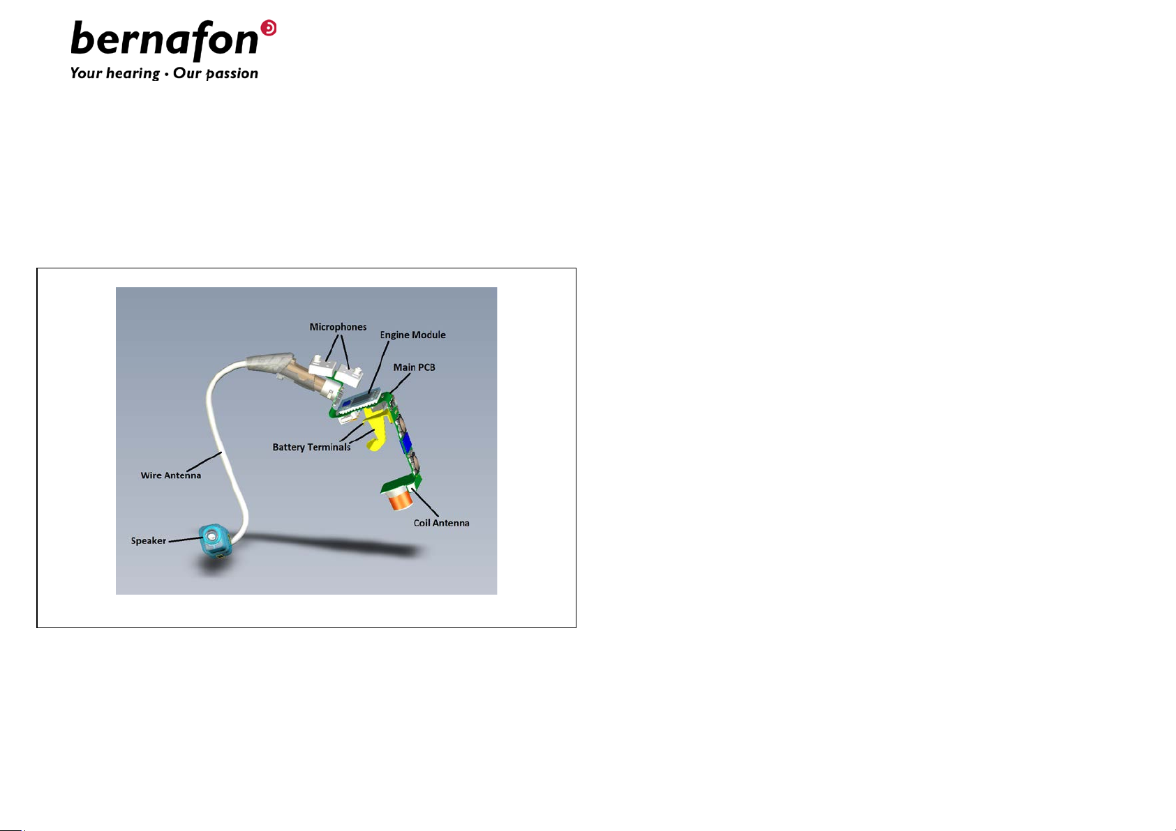
The radio model is implemented in an engine module mounted on the
main PCB with connections to the antennas, the microphones, the speaker
and the battery terminals. The radio model can be seen in 3D overview to
the left:
The 3.84 MHz radio is a low power, short range, inductive radio
transceiver working at a single channel at 3.84 MHz using MSK
modulation with 320 kbit/s data rate and connected to a small coil
antenna. The 2.4 GHz radio is a Bluetooth Low Energy (BLE)
transceiver using GFSK modulation with 1 Mbit/s data rate also capable
of proprietary receiver modes with higher data rates and connected to a
short wire antenna.
Aurora miniRITE T 312 Rc Radio Model – 3D overview
Page 2
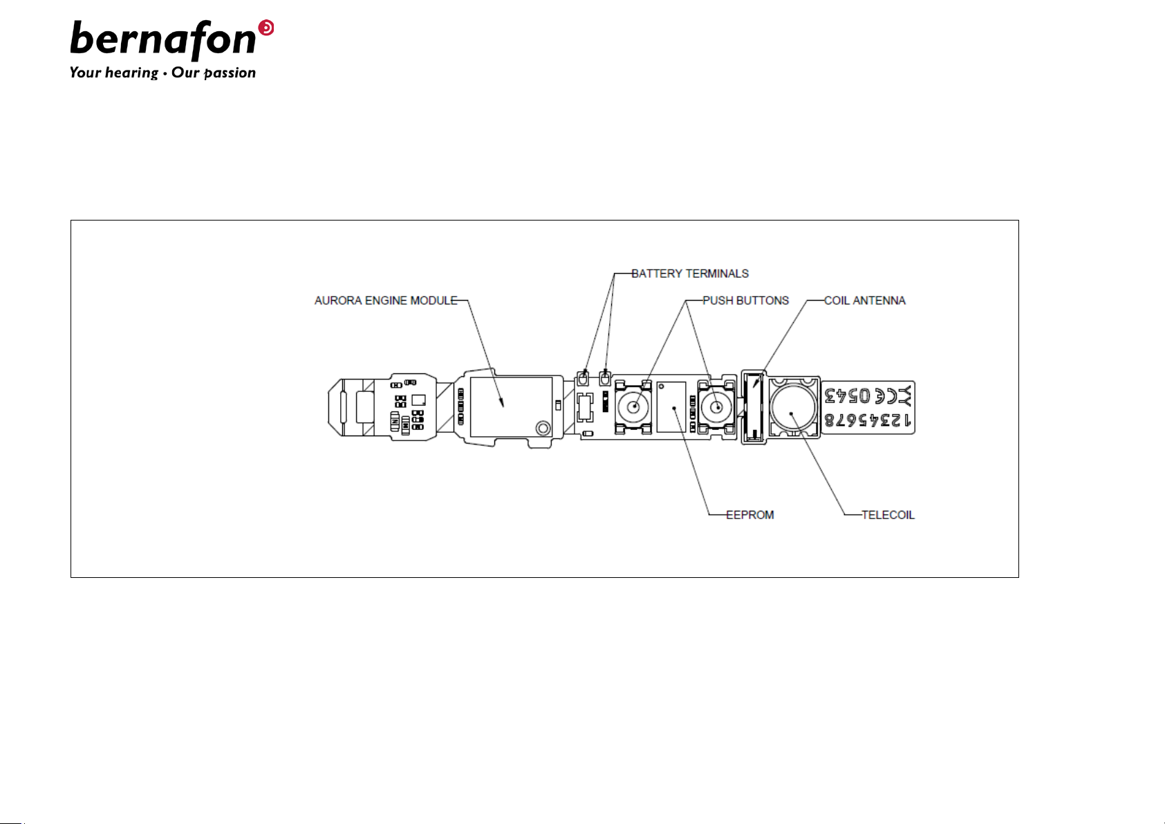
Below the main flex PCB of the Aurora miniRITE 312 T Rc radio model with the most important electrical and electro-mechanical components can be seen:
Aurora miniRITE 312 T Rc Radio Model – Main PCB – Top side
The most important part of the radio model is the Engine Module mounted on the main flex PCB, which connects it to both the EEPROM memory and all external
connections: On the top side these are the microphones, the battery terminals and the push button. The telecoil is also used for wireless battery charging.
The Aurora miniRITE 312 T Rc radio model requires only a single cell rechargeable battery and an external speaker (also incl. the wire antenna for the
Bluetooth radio part) to be attached and plastic shells, defining the industrial design of a hearing aid end product and holding everything together, in order to be
operational.
Page 3

On the bottom side of the main PCB of the Aurora miniRITE 312 T Rc radio model the connector for the speaker unit assembly (where the wire antenna for the
Bluetooth radio is an integrated part), the programming connector, EEPROM memory and coil antenna for the 3.84 MHz radio can be seen:
Aurora miniRITE 312 T Rc Radio Model – Main PCB – Bottom side
The most important parts inside the Engine module are a Digital-Signal-Processor (DSP), a radio Front-End (FE) chip for the 3.84 MHz radio part and an RF chip
for the Bluetooth radio part – all mounted on a small rigid PCB again mounted on the main flex PCB. The Aurora miniRITE 312 T Rc radio model also includes all
voltage regulators and buffered data programming inputs on board. The DSP is the main processor controlling the functionality of both radios in the Aurora
miniRITE 312 T Rc radio model.
The Aurora miniRITE 312 T Rc radio model is intended to be installed in Bernafon and affiliated wireless hearing aid devices of the miniRITE 312 T Rc (ReceiverIn-The-Ear) wearing style.
Page 4

IC:
7031A-AUMRTRC
Bernafon Radio Model - Regulatory Label Information for USA & Canada
Radio Model Name: Aurora miniRITE 312 T Rc
Contains: FCC ID: U6XAUMRTRC
NOTICE:
This device complies with Part 15 of the FCC Rules and with RSS-210 and RSS-247 of Industry Canada.
Operation is subject to the following two conditions:
(1) This device may not cause harmful interference, and
(2) This device must accept any interference received, including
interference that may cause undesired operation.
Changes or modifications made to this equipment not expressly approved by Bernafon AG may void the FCC authorization to operate this equipment.
Le présent appareil est conforme aux CNR d'Industrie Canada applicables aux appareils radio exempts de licence. L'exploitation est autorisée aux deux conditions suivantes:
(1) l'appareil ne doit pas produire de brouillage, et
(2) l'utilisateur de l'appareil doit accepter tout brouillage radioélectrique subi, même si le brouillage est susceptible d'en
compromettre le fonctionnement.
 Loading...