


BERKO HUHAA320FC, HUHAA324FC, HUHAA327FC, HUHAA348FC, HUHAA520FC User Manual
...HUHAAFC Series
Modular Unit Heaters
Installation, Operation & Maintenance Instructions
Specifications
Basic Model |
Height |
Width |
Depth |
Mounting |
Wiring |
|||
Weight |
Compartment |
|||||||
No. |
in (mm) |
in. (mm) |
in. (mm) |
lbs. (kg) |
Volume |
|||
HUHAA320FC |
|
|
|
|
|
27 (12.2) |
|
|
|
|
|
|
|
|
|
|
|
HUHAA324FC |
|
|
|
|
|
27 (12.2) |
|
|
|
|
|
|
|
|
|
|
|
HUHAA327FC |
|
|
|
|
|
27 (12.2) |
|
|
|
|
|
|
|
|
|
|
|
HUHAA348FC |
16 |
14 |
71/2 |
30 (13.6) |
90 in3 |
|||
|
|
|||||||
HUHAA520FC |
(406.4) |
(355.6) |
(190.5) |
27 (12.2) |
(14.70 cm3) |
|||
HUHAA524FC |
|
|
|
|
|
27 (12.2) |
|
|
|
|
|
|
|
|
|
|
|
HUHAA527FC |
|
|
|
|
|
27 (12.2) |
|
|
|
|
|
|
|
|
|
|
|
HUHAA548FC |
|
|
|
|
|
30 (13.6) |
|
|
|
|
|
|
|
|
|
|
|
HUHAA724FC |
|
|
|
|
|
38 (17.2) |
|
|
|
|
|
|
|
|
38 (17.2) |
|
|
HUHAA720FC |
|
|
|
|
|
|
||
|
|
|
|
|
|
38 (17.2) |
|
|
HUHAA727FC |
|
|
|
|
|
100 in3 |
||
|
3 |
19 |
7 |
1 |
/2 |
38 (17.2) |
||
HUHAA748FC |
||||||||
21 /4 |
|
(1639 cm3) |
||||||
|
(552.5) |
(482.6) |
(190.5) |
|
||||
|
38 (17.2) |
|||||||
HUHAA1020FC |
||||||||
|
|
|
|
|
|
|||
|
|
|
|
|
|
38 (17.2) |
|
|
HUHAA1024FC |
|
|
|
|
|
|
||
|
|
|
|
|
|
38 (17.2) |
|
|
HUHAA1027FC |
|
|
|
|
|
|
||
|
|
|
|
|
|
38 (17.2) |
|
|
HUHAA1048FC |
|
|
|
|
|
|
||
Basic Mode |
Height |
Width |
Depth |
Mounting |
Wiring |
|
Weight |
Compartment |
|||||
No. |
in (mm) |
in. (mm) |
in. (mm) |
lbs. (kg) |
Volume |
|
HUHAA1520FC |
|
|
|
54 (24.5) |
|
|
|
|
|
|
|
|
|
HUHAA1524FC |
|
|
|
50 (22.7) |
|
|
|
|
|
|
|
|
|
HUHAA1548FC |
213/4 |
19 |
12 3/4 |
50 (22.7) |
140 in3 |
|
HUHAA2020FC |
(552.5) |
(482.6) |
(323.9) |
60 (27.2) |
(2295 cm3) |
|
|
|
|
|
|||
|
|
|
|
|
|
|
HUHAA2024FC |
|
|
|
55 (24.9) |
|
|
|
|
|
|
|
|
|
HUHAA2048FC |
|
|
|
55 (24.9) |
|
|
|
|
|
|
|
|
|
HUHAA2524FC |
|
|
|
89 (40.4) |
|
|
|
|
|
|
|
|
|
HUHAA2548AFC |
30 |
265/8 |
113/4 |
89 (40.4) |
504 in3 |
|
HUHAA3020FC |
89 (40.4) |
|||||
(76.2) |
(676.4) |
(298.5) |
(8260 cm3) |
|||
HUHAA3024FC |
|
|
|
89 (40.4) |
|
|
|
|
|
|
|
|
|
HUHAA3048AFC |
|
|
|
89 (40.4) |
|
|
|
|
|
|
|
|
|
HUHAA4024FC |
|
|
|
119 (54.0) |
|
|
HUHAA4048FC |
30 |
265/8 |
171/4 |
119 (54.0) |
648 in3 |
|
|
|
|||||
HUHAA5024FC |
(76.2) |
(676.4) |
(435.1) |
119 (54.0) |
(10620 cm3) |
|
HUHAA5020FC |
|
|
|
119 (54.0) |
|
|
HUHAA5048FC |
|
|
|
119 (54.0) |
|
ECR 41912 |
07/19 |
5200-11106-004 |

IMPOrtaNt INStrUCtIONS
WarNING !
wHEN UsiNg ELECTRiC AppLiANCEs, BAsiC pRECAUTioNs sHoULD ALwAys BE foLLowED To REDUCE THE RisK of fiRE, ELECTRiC sHoCK, AND iNJURy To pERsoNs, iNCLUDiNg THE foLLowiNg:
1.Read all instructions before installing or using this heater.
2.This heater is a commercial/industrial product not intended for use in a residential setting.
3.This heater is hot when in use. To avoid burns, do not let bare skin touch hot surfaces. Keep combustible materials, such as furniture, pillows, bedding, papers, clothes, etc. and curtains at least 3 feet (0.9 m) from the front of the heater.
4.Extreme caution is necessary when any heater is used by or near children or invalids and whenever the heater is left operating and unattended.
5.This heater has hot and arcing or sparking parts inside and is not intended for use in hazardous atmospheres where flammable vapors, gases, liquids or other combustible atmospheres as defined in the National Electrical Code are used or stored. failure to comply can result in explosion or fire.
6.Do not operate any heater after it malfunctions. Disconnect power at service panel and have heater inspected by a reputable electrician before using.
7.Do not use outdoors.
8.To disconnect heater, turn controls to off, and turn off power to heater circuit at main disconnect panel.
9.Do not insert or allow foreign objects to enter any ventilation or exhaust opening as this may cause an electric shock, fire, or damage to the heater.
10.To prevent a possible fire, do not block air intake or exhaust in any manner.
11.Use this heater only as described in this manual. Any other use not recommended by the manufacturer may cause fire,
12.This heater is not intended for use in special environments. Do not use in damp or wet locations such as marine or greenhouse or in areas where corrosive or chemical agents are present.
13.when installing, see iNsTALLATioN iNsTRUCTioNs for additional warnings and precautions.
14.for safe and efficient operation, and to extend the life of your heater, keep your heater clean - see MAiNTENANCE iNsTRUCTioNs.
SaVE tHESE INStrUCtIONS
INStallatION INStrUCtIONS
WarNING |
! |
|||
|
|
|
||
To prevent a possible fire, injury to persons or damage to the |
4. |
To reduce the risk of fire, do not store or use gasoline or |
||
heater, adhere to the following: |
|
other flammable vapors and liquids in the vicinity of the |
||
1. Disconnect all power coming to heater at main service panel |
|
heater. |
|
|
5. |
The ceiling or wall mounting structure and the anchoring |
|||
before wiring or servicing. |
||||
Important Note: This heater must be installed by a qualified |
|
provisions must be of sufficient strength to support the com- |
||
|
bined weight of the heater and mounting bracket. |
|||
person. |
|
|||
6. |
All built-in thermostats: if the heater is used to prevent pip- |
|||
2. All wiring procedures and connections must be in accor- |
||||
|
ing or |
liquids from freezing, and if the thermostat is set |
||
dance with the National and Local Codes having jurisdiction |
|
|||
|
below 45° f (7°C), the fan must run continuously. |
|||
and the heater must be grounded. |
|
|||
7. |
The heater must be mounted at least 7’ (2134 mm) above |
|||
3. Verify the power supply voltage coming to heater matches |
||||
|
the floor to avoid accidental contact with the fan blade which |
|||
the ratings as shown on the heater nameplate. |
|
|||
|
could cause injury. |
|||
|
|
|||
CaUtION: ENERgiziNg HEATER AT A VoLTAgE gREATER |
8. |
Keep at least 5’ clearance in front of the heater. Refer to |
||
THAN THE VoLTAgE pRiNTED oN THE NAMEpLATE wiLL |
|
Table 1 for side, top and back clearance requirements. |
||
DAMAgE THE HEATER AND VoiD THE wARRANTy AND |
9. |
Do not |
mount mercury type thermostat directly on unit. |
|
CoULD CAUsE A fiRE. |
||||
|
Vibration could cause heater to malfunction. |
|||
|
|
|||
|
|
|
|
|
Heater location Instructions
Arrange units so that discharge air streams:
a.are subjected to a minimum of interference from columns, machinery and partitions;
b.wipe exposed walls without blowing directly at them;
c.are directed away from room occupants in comfort heating;
d.are directed along the windward side when installed in a building exposed to a prevailing wind.
Locate thermostats approximately 5' (1524mm) above the floor on interior partition walls or post away from cold drafts, internal heat sources and away from heater discharge air streams.
small rooms can be heated by one unit heater.
Large rooms require multi-unit installations. Number and capacity of units will be determined by volume of building and square feet of floor area to be heated. Arrange units to provide perimeter air circulation where each unit supports the air stream from another.
2

Mounting the Heater - General
The heater may be mounted to discharge the heated air either horizontally or vertically. When the heater is mounted for vertical discharge, it is recommended that the heater be positioned so that the access door will open away from the wall to provide greater access to the wiring and control compartment. If the heater is to be mounted with the access door facing a wall, the heater must be mounted far enough from that wall to allow full opening of the access door (a distance approximately equal to the width of the heater, check clearance before installing). Refer to Table 1 for wall and ceiling clearances before mounting heater.
The heater may be mounted for either vertical or horizontal discharge by the use of threaded rods. (Refer to Table 2 for threaded rod sizes required.) Observe the detailed procedures in the following installation instructions.
The heater may also be suspended from the wall or ceiling by means of an optional mounting bracket (type MMB or MCMB) which permits horizontal pivoting of the heater.
After the heater is installed, the louvers may be positioned to direct the heated air in the desired direction. When the heater is installed for horizontal discharge, the louvers should direct the air either straight ahead or downward. Directing the air upward may cause the heated air to remain in the ceiling area and waste energy.
Table 1. Wall and Ceiling Clearance, inches (mm)
Minimum Floor to Bottom of heater clearance is 7 feet
Unit |
Discharge |
Ceiling |
Side Wall |
Back Wall |
|
3 & 5 kW |
Horiz. |
2 (50.8) |
6 (152.4) |
9 (228.6) |
|
Vert. |
6 (152.4) |
18 (457.2) |
18 (457.2) |
||
|
|||||
7.5 to 10 kW |
Horiz. |
6 (152.4) |
6 (152.4) |
13 (330.2) |
|
Vert. |
6 (152.4) |
24 (609.6) |
24 (609.6) |
||
|
|||||
15 to 20 kW |
Horiz. |
6 (152.4) |
9 (228.6) |
121/2 (317.5) |
|
Vert |
6 (152.4) |
24 (609.6) |
24 (609.6) |
||
|
|||||
25 to 50 kW |
Horiz. |
16 (406.4) |
12 (304.8) |
181/2 (470.0) |
|
Vert. |
12 (304.8) |
36 (914.4) |
39 (914.4) |
||
|
|||||
|
CEILING |
|
BACK WALL |
|
|
MOUNTING |
|
THREADED |
|
|
|
ROD |
|
HOLES |
B |
D |
|
|
|
MOUNTING |
|
|
|
|
|
|
|
S |
|
LOCK NUT |
|
|
|
I |
|
|
|
|
D |
||
B |
|
|
|
E |
|
|
|
|
W |
||
A |
|
|
|
||
C |
|
A |
|
A |
|
K |
|
|
|
L |
|
W |
|
|
|
L |
|
|
|
|
|
||
A |
|
|
|
|
|
L |
|
|
|
|
|
L |
|
|
|
|
|
|
|
|
|
C |
|
|
|
UNIT HEATER |
(TOP VIEW) |
|
Figure 1. Horizontal Discharge Mounting and Spacing.
Table 2. Rod Thread and Spacing Dimensions, inches (mm) for Horizontal Discharge
|
Unit |
Rod Thread |
A |
B |
C |
D |
||
|
Type |
|||||||
3 |
- 5 kW |
|
|
|
|
6 |
41/16 |
3/4 |
|
|
61/16 |
|
(152.4) |
(103.1) |
(19.0) |
||
|
|
|
|
|
||||
|
|
|
|
(153.9) |
|
|
|
|
7.5 - 10 kW |
5/16 - 18 |
|
|
87/8 |
51/8 |
3/4 |
||
|
|
|
||||||
|
|
|
|
|
|
|||
15 |
- 20 kW |
|
|
113/8 |
|
(225.6) |
(130.3) |
(19.0) |
|
|
(289.0) |
|
|
|
|
||
|
|
|
|
|
|
|
|
|
|
|
|
|
|
|
|
|
|
25 |
- 30 kW |
|
|
109/16 |
|
14 - 12 |
63/16 |
5/8 |
|
|
(268.2) |
|
(368.3) |
(157.2) |
(16.0) |
||
|
|
3/8 - 16 |
|
|
||||
|
|
|
|
|
|
|
|
|
40 |
- 50 kW |
|
1515/16 |
|
14 - 12 |
63/16 |
5/8 |
|
|
|
|
||||||
|
|
(404.9) |
|
(368.3) |
(157.2) |
(16.0) |
||
|
|
|
|
|
||||
|
|
|
|
|
|
|
|
|
Horizontal Discharge (Rod-mount from Ceiling)
1.Install four threaded mounting rods in the threaded holes and secure in place using lock nuts. (See Table 2).
2.Securely attach the four mounting rods to the ceiling. (Refer to Table 1 for wall and ceiling clearances, and Table 2 for mounting rod spacing).
Table 3. Rod Thread and Spacing Dimensions, inches (mm) for Vertical Discharge
Unit |
Rod Thread |
E |
F |
G |
H |
|
Type |
||||||
3 - 5 kW |
|
6 |
93/4 |
2 |
41/16 |
|
|
(152.4) |
247.7) |
(50.8) |
(103.1) |
||
|
|
|||||
|
5/16 - 18 |
|
|
|
|
|
|
|
|
|
|
||
7.5 - 20 kW |
87/8 |
145/8 |
2 |
51/8 |
||
|
||||||
|
(225.6) |
(371.6) |
(50.8) |
(130.3) |
||
|
|
|||||
|
|
|
|
|
|
|
25 - 30 kW |
3/8 - 16 |
141/2 |
211/4 |
23/16 |
63/16 |
|
(368.3) |
(539.8) |
(56.0) |
(157.2) |
|||
|
|
|||||
|
|
|
|
|
|
|
CEILING |
ACCESS |
LOCK NUT |
DOOR |
|
B
A
C
K
W
A
L
L
CLEARANCE EQUAL TO WIDTH OF
HEATER TO PERMIT FULL OPEN-
ING OF THE ACCESS DOOR
|
|
BACK WALL |
|
|
|
E |
|
MOUNTING |
|
|
|
ROD (4) |
G |
|
S |
|
|
|
I |
|
|
|
D |
|
THREADED |
|
E |
|
MOUNTING |
|
W |
|
HOLES |
F |
|
|
A |
||
|
|
|
L |
|
|
|
L |
(TOP VIEW) |
H |
Figure 2. Vertical Discharge Mounting and Rod Spacing
Vertical Discharge (Rod-Mount from Ceiling)
1.Remove bolts from the threaded holes in the back of the heater.
2.Install four threaded mounting rods in the threaded holes and and secure in place using lock nuts.
3.Securely attach the four mounting rods to the ceiling. (Refer to Table 1 for wall and ceiling clearances, and Table 3 for mounting rod spacing dimensions.)
Wiring Branch Circuit (Power)
1.Connect heater only to the voltage, amperage and frequency specified on the nameplate.
2.Field wiring must be properly sized to carry the amperage in accordance with the NEC.
3.The access door is hinged. There are either one or two screws accessible from the side that must be loosened to gain access. These screws are the captive type; do not try to remove them.
4.A knockout is provided in the back of the heater close to the power terminal block and the control terminal board. The control terminal board knockout is 1/2 inch (12.7 mm) conduit size. The power terminal block knockout is multiple diameter. Use the diameter that fits the required conduit size.
5.A ground terminal is provided near the power terminal board. The ground wire should be connected before other connections are made.
6.The power terminal block is equipped with box terminals sized to accept the correct size power supply wire. Branch circuit wire rated min 600V, 60° C is acceptable for heaters rated up to 80 amps. For heaters rated more than 80 amps, branch circuit wire must be rated at least 75°C. Either aluminum or copper wire is satisfactory for connection to the heater power terminal block box terminal. Copper wire is recommended and must be used with built-in disconnect switch.
3
7.Each heater has a wiring diagram affixed to the inside of the access door. Consult this diagram before making any field connections.
Important Note - Installation Screw Lug Torque:
During transportation it is possible screw lug connections can loosen. After installation, before power is turned on to the heater, check all screw lug connections for tightness to a recommended minimum torque of 35 in-lbs. (3.9 N-m). Loose connections may present a hazard.
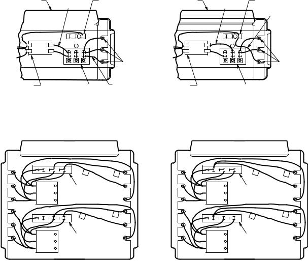
8.Single or three-phase power connections may be used with heater models HUHAA524FC, HUHAA520FC, HUHAA720FC, HUHAA724FC, HUHAA1024FC, HUHAA1020FC, and HUHAA1520FC. These units are factory wired for single-phase operation. If these heaters are for use with three-phased power, reconnect the wires as indicated in the wiring diagram attached to the heater. Additional information can be found by looking at the wiring illustrations in Figures 3a and 3b and following the directions shown below.
On models HUHAA524FC, HUHAA520FC, HUHAA724FC, HUHAA720FC, HHUHAA1520FC, HUHAA1024FC, and HUHAA1020FC, (Figure 3a), move only the two wires marked “A1”and marked “B1”; do not move or change any other wiring. The element lead wire marked “B1” which is factory connected to the power terminal block (terminal located closest to the elements) must be moved to terminal “B” on the three-phase terminal block.
HEATER FRONT |
LEAD WIRE |
3 PHASE BLOCK |
||||
|
|
|
|
"A1" |
|
|
|
|
|
|
|
|
|
|
|
|
|
|
|
|
|
|
|
|
|
|
|
|
|
|
|
|
|
|
|
|
|
|
|
|
|
TO ELEMENTS |
B |
|
A |
|
|
|
ELEMENTS |
|
|
|
|
CONTACTOR |
|
LEAD WIRE |
POWER TERMINAL BLOCK |
"B1" |
|
(OR P2) |
|
|
|
|
FACTORY-WIRED FOR SINGLE-PHASE POWER
HEATER FRONT |
LEAD WIRE |
3 PHASE BLOCK |
|
"A1" |
|
|
LEAD WIRE |
|
|
"B1" |
|
TO ELEMENTS |
B |
|
A |
||
ELEMENTS |
||
|
CONTACTOR |
POWER TERMINAL BLOCK |
|
(OR P2) |
||
|
FIELD-WIRED FOR THREE-PHASE POWER
Figure 3a. Wiring Connections for Single-Phase and Three-Phase Power(HUHAA524FC, HUHAA520FC, HUHAA724FC, HUHAA720FC, HUHAA1024FC, HUHAA1020FC
B |
C |
D |
D |
C |
|
|
|
||
|
|
|
1 |
|
|
|
|
|
1 |
|
|
3 PHASE BLOCK |
|
|
|
|
|
D |
C |
|
|
|
1 |
|
B |
C |
D |
1 |
|
3 PHASE BLOCK
B |
C |
D |
D |
C |
|
|
|
||
|
|
|
1 |
|
|
|
|
|
1 |
|
|
3 PHASE BLOCK |
|
|
|
|
|
D |
C |
|
|
|
1 |
|
B |
C |
D |
1 |
|
3 PHASE BLOCK
FACTORY-WIRED FOR SINGLE-PHASE POWER |
FIELD-WIRED FOR THREE-PHASE POWER |
Figure 3b. Wiring Connections for Single-Phase and Three -Phase Power (HUHAA1520FC)
4
The relay (contactor) lead wire “A1” must be moved from the end terminal of the power terminal block (terminal closest to the contactor or control terminal board) to the “A” terminal of the lower terminal block (center terminal).
Model HUHAA1520FC (Figure 3b) has two three-phase terminal blocks located adjacent to the relays (contactors). Move only the two wires marked “C1” and “D1” on each of these two three-phase terminal blocks to terminal “B”. Do not move or change any other wires.
9.Electrical Accessories, either kits or factory-installed options, are shown connected by a dash line on the heater wiring diagram.
10.208/240 VOLT HEATER: The heaters are wired for 240V from factory. When heater is to be connected to 208V supply, the transformer leads MUST BE interchanged. For units rated 30/40kW or higher, interchange ORANGE and RED primary leads. The black colored lead is the COMMON for the transformer (50VA) provided with the high wattage units. For lower kW rated heaters, interchange BLACK and RED primary leads. The WHITE colored lead is the COMMON for the control transformer provided with these heaters. Always refer to the wiring diagram on the cover of the heater before making this reconnection of tranformer primary leads.
Control Wiring
LINE VOLTAGE IS PRESENT ON SOME OF THE TERMINALS ON THE CONTROL TERMINAL BOARD. ALWAYS DISCONNECT THE POWER FROM THE HEATER BEFORE MAKING ANY CONNECTIONS TO THE CONTROL BOARD TO PREVENT ELECTRIC SHOCK HAZARD.
1.Use min. 600 volts, NEC Class 1 insulated wire for all control circuit wiring.
2.Use a crimp-on type fork terminal on the wire ends that attach to the control terminal board if more than one connection is to be made under the terminal screw.
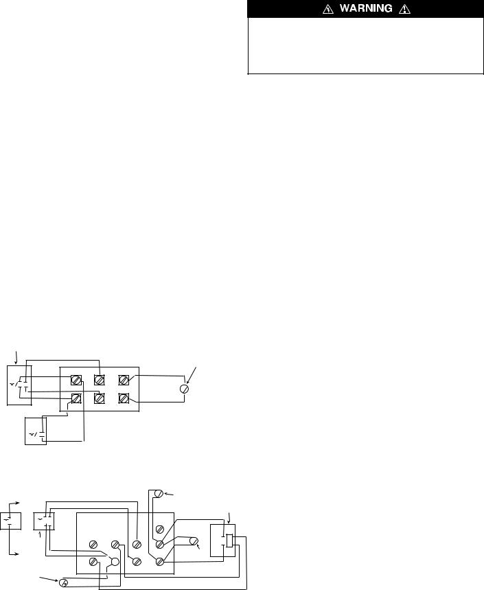
3.On units not provided with internal contactor (3 & 5 KW), refer to Figure 4 for wiring diagram.
NOTE: Thermostat and control circuit wiring must be suitable to handle the full load of the heater (example HUHAA520FC is rated 24amps)
4.On units provided with internal contactor (units rated 7 KW and higher) refer to Figure 5 for wiring diagram. Control wiring must be rated minimum 18 AWG.
CAUTION: To prevent a possible fire or damage to heater, if a two stage thermostat is provided, it MUST be wired so Stage 1 turns the rear heating element (where fan control is located) on first and off last. Stage 2 MUST turn on elements other than the rear element as the need for additional heat is required and will turn on last and off first.
2-STAGE
INTERNAL THERMOSTAT
REMOTE SUMMER RED FAN SWITCH (MRFS-1)
OR SUMMER FAN SWITCH MCFS (MANUAL)
MT-2 |
|
|
|
BLACK |
|
|
|
H1 |
H2 |
F2 |
S |
RED |
|
|
|
BLACK |
|
|
|
P1 |
P2 |
F1 |
|
MT-1
IMPORTANT! FOR 2 STAGE THERMOSTATS, USE:
1. H1 AND P1 FOR STAGE 1 CONNECTIONS 2. H2 AND P2 FOR STAGE 2 CONNECTIONS
OPERATING
INSTRUCTIONS
1.Heater must be properly installed before operation.
2.Turn power supply to heater “ON” at main switch panel.
3.Where applicable, refer to control accessory instructions regarding proper operation of any controls or accessories used with the heater.
NOTES:
1.THIS STYLE CONTROL TERMINAL BOARD USED WITH MODELS HUHAA324FC, HUHAA327FC, HUHAA320FC, HUHAA524FC, HUHAA527FC, AND HUHAA520FC.
2.WHEN UNIT IS WIRED FOR SINGLE-PHASE, JUMPER H1 TO H2. IF SINGLEPOLE THERMOSTAT IS USED WITH SINGLE-PHASE UNIT, CONNECT THERMOSTAT LEADS TO P1 AND H1.
3.EXTERNAL LINE VOLTAGE THERMOSTATS SHOULD BE TREATED AS SINGLE STAGE ONLY.
Figure 4. Control Terminal Board (for Heaters Without Contactors)
S |
REMOTE SUMMER FAN |
|
SWITCH (MRFS-1) |
RED
BLACK TO W1
BLACK FAN RELAY
(FOR MRFS-2 AMD MHRT)
T |
T |
|
|
|
|
|
MT-1 |
MT-2 |
|
|
|
|
|
|
2-STAGE |
|
|
|
TR |
|
|
INTERNAL |
|
|
|
S |
|
|
THERMOSTAT |
|
|
|
|
|
|
|
BLACK |
G |
|
|
SUMMER |
|
|
RED |
W2 |
F1 |
||
|
|
|
|
|
FAN |
|
|
RED TO R |
|
|
|
|
SWITCH |
|
|
|
|
|
|
|
|
MHRT HEAT RECOVERY |
C |
R |
W1 |
F2 |
|
|
|
|
|
|
|
|
|
THERMOSTAT OR |
|
|
|
|
|
|
REMOTE FAN |
T |
|
|
|
|
|
SWITCH (MRFS-2) |
|
|
|
|
|
|
|
|
|
|
|
NOTES:
1.THIS STYLE CONTROL TERMINAL BOARD USED WITH MODELS EXCEPT HUHAA324FC, HUHAA327FC, HUHAA320FC, HUHAA524FC, HUHAA527FC, AND HUHAA520FC.
2.REMOVE JUMPER W1 TO W2 WHEN 2-STAGE THERMOSTAT IS USED.
3.*ONLY ONE OF THESE ACCESSORIES MAY BE INSTALLED IN A SINGLE HEATER.
4.EXTERNAL LINE VOLTAGE THERMOSTATS SHOULD BE TREATED AS SINGLE STAGE ONLY.
IMPORTANT! FOR 2 STAGE THERMOSTATS, USE:
1.W1 AND R FOR STAGE 1 CONNECTIONS
2.W2 AND R FOR STAGE 2 CONNECTIONS
Figure 5. Control Terminal Board (for Heaters With Contactors)
5

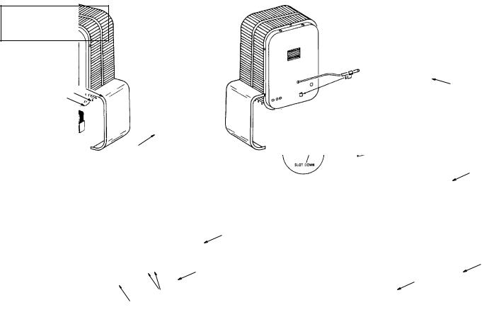
How to Reset Manual Reset Safety Limit (Factory Installed Option Only)
The manual reset switch is located internally on the rear of the heater. On the 3KW and 5KW models, the access to the reset button is on the right side (when facing rear of heater); on all other models it is near the top rear of the heater.
The manual reset limit is in series with the automatic recycling protector (limit). The manual reset limit will not reset until the heater has cooled and the button is pushed in.
DO NOT TAMPER WITH OR BYPASS ANY SAFETY LIMITS INSIDE HEATER.
CAUTION - DO NOT CONTINUE TO ATTEMPT TO USE THE HEATER IF THE SAFETY CONTROL REPEATEDLY OPERATES AFTER BEING RESET. TO DO SO COULD PERMANENTLY DAMAGE THE HEATER OR CREATE A FIRE OR SAFETY HAZARD.
It is important to keep this heater clean. Your heater will give you years of service and comfort with only minimum care. To assure efficient operation follow the simple instructions below.
ALL SERVICING BEYOND SIMPLE CLEANING THAT REQUIRES DISASSEMBLY SHOULD BE PERFORMED BY QUALIFIED SERVICE PERSONNEL.
TO REDUCE RISK OF FIRE AND ELECTRIC SHOCK OR INJURY, DISCONNECT ALL POWER COMING TO HEATER AT MAIN SERVICE PANEL AND CHECK THAT THE ELEMENT IS COOL BEFORE SERVICING OR PERFORMING MAINTENANCE.
User Cleaning Instructions:
1.After the heater has cooled, a vacuum cleaner with brush attachment may be used to remove dust and lint from exterior surfaces of the heater including the grille openings.
2.With a damp cloth, wipe dust and lint from grille and exterior surfaces.
3.Return power to heater and check to make sure it is operating properly.
Maintenance Cleaning Instructions:
(To be performed only by Qualified Service Personnel)
At least annually, the heater should be cleaned and serviced by a qualified service person to assure safe and efficient operation. This should include as necessary, vacuuming dust and debris from the elements and fan, and checking all screw lug connections for tightness to a recommended minimum torque of 35 inlbs. (3.9 N-m). After completing the cleaning and servicing, the heater should be fully reassembled and checked for proper operation.
MAINTENANCE
INSTRUCTIONS
It is important to keep this heater clean. Your heater will give you years of service and comfort with only minimum care. To assure efficient operation follow the simple instructions below.
ALL SERVICING BEYOND SIMPLE CLEANING THAT REQUIRES DISASSEMBLY SHOULD BE PERFORMED BY QUALIFIED SERVICE PERSONNEL.
TO REDUCE RISK OF FIRE AND ELECTRIC SHOCK OR INJURY, DISCONNECT ALL POWER COMING TO HEATER AT MAIN SERVICE PANEL AND CHECK THAT THE ELEMENT IS COOL BEFORE SERVICING OR PERFORMING MAINTENANCE.
User Cleaning Instructions:
1.After the heater has cooled, a vacuum cleaner with brush attachment may be used to remove dust and lint from exterior surfaces of the heater including the grille openings.
2.With a damp cloth, wipe dust and lint from grille and exterior surfaces.
3.Return power to heater and check to make sure it is operating properly.
6
HUHAA FC
Built-in Controls
Key No. |
Description |
Part Number |
1 |
Thermostat, One Pole (MT-1) |
5813-0036-000 |
|
|
|
|
Thermostat, Two Stage (MT-2) |
5813-0035-000 |
|
|
|
2 |
Knob, Thermostat |
3301-0060-000 |
|
|
|
3 |
Label, Thermostat |
3502-1781-000 |
|
|
|
4 |
Screws, Fl. Hd., 6-32 x 1/4 |
5202-7009-021 |
|
|
|
5 |
Clip, Thermostat |
1403-0041-000 |
|
|
|
6 |
Switch, 25A, OEM |
5216-0132-000 |
|
|
|
|
Switch, 25A, K & N |
5216-0204-000 |
|
|
|
|
Switch, 63A, OEM |
5216-0131-000 |
|
|
|
|
Switch, 63A, K & N |
5216-0203-000 |
|
|
|
|
Switch 25A, Electro |
5216-0200-000 |
|
|
|
7 |
Screw, M4 x 10, Rd. Hd., (25A) |
— |
|
|
|
|
Screw, 63A, M5 x 16, Rd. Hd. |
— |
|
|
|
8 |
Knob, 25A, OEM “T1” |
OEM “T1” |
|
|
|
|
Knob, 25A, K & N |
K & N S1B 6001 |
|
|
|
|
Knob, 63A, OEM |
OEM “S4” |
|
|
|
|
Knob, 63A, K & N |
K & N S2B G001 |
|
|
|
|
Knob, Electro |
EI 141747 |
|
|
|
9 |
Switch, Toggle, 600V |
5216-0130-000 |
|
|
|
10 |
Relay, Fan, 24V Coil |
5018-0008-000 |
|
|
|
11 |
Switch Assembly |
5216-0199-000 |
|
|
|
12 |
Manual Reset Limit |
4520-0012-000 |
|
|
|
Heater Replacement Parts
Key No. |
Description |
Part Number |
1 |
Spring, Element (used on 20kW and below only) |
5208-0073-000 |
|
Spring, Element (used on 25kW and below only) |
5208-0073-001 |
|
|
|
2 |
Spring, Capillary Tube |
5208-0072-000 |
|
|
|
3 |
Spring, Element Retainer |
5208-0074-000 |
|
|
|
4 |
Switch (used on 25kW thru 50kW only) |
5216-7076-001 |
|
|
|
5 |
Insulator (used on 25kW thru 50kW only) |
2900-0031-000 |
|
|
|
6 |
Bracket Extension |
|
|
(used on 15kW, 20kW, 40kW and 50kW only) |
1215-0282-000 |
7 |
Switch Bracket |
1215-0256-000 |
|
|
|
8 |
Fan Delay |
4520-0010-000 |
|
|
|
14 |
Speed Nut |
4100-7036-026 |
|
|
|
15 |
Bracket, Captive Screw (used on 3kW thru 20kW only) |
1215-0291-000 |
|
Bracket, Captive Screw (used on 25kW thru 50kW only) |
1215-0289-000 |
17 |
Protector, Linear Limit (used on 3kW thru 5kW only) |
4520-0011-000 |
|
Protector, Linear Limit (used on 7kW thru 20kW only) |
4520-0011-001 |
|
Protector, Linear Limit (used on 25kW thru 50kW only) |
4520-0011-002 |
20 |
Clamp (used on 20kW thru 50kW only) |
1417-5004-000 |
|
Bracket, Mounting Capacitor (used on 20kW, 208v only) |
1215-0314-000 |
22 |
Terminal Lug (used on 7kW thru 50kW only) |
3504-7002-001 |
25 |
Bushing (used on 20kW thru 50kW only) |
25221-60131 |
26 |
Washer, Ground (used on 3kW thru 5kW only) |
6401-0084-000 |
27 |
Screw, Ground (used on 3kW thru 5kW only) |
5202-0290-002 |
28 |
Louver (used on 3kW thru 5kW only) |
3503-0036-000 |
|
Louver (used on 7kW thru 20kW only) |
3503-0036-001 |
|
Louver (used on 25kW thru 50kW only) |
3503-0036-002 |
29 |
Spring, Louver |
5208-7005-001 |
|
|
|
32 |
Terminal Block, 3-Phase (used where models |
|
|
can be 1 or 3 phase) |
5823-0003-000 |
33 |
Terminal Doublers (used where required) |
5819-7012-005 |
|
|
|
BUILT-IN CONTROLS — |
|
|
|
||
Made-to-Order Units Only |
|
|
|
||
|
|
|
|
SINGLE-POLE |
|
|
|
|
|
THERMOSTAT,TWO-STAGE |
|
|
|
|
|
THERMOSTAT, HEAT |
|
|
|
|
|
RECOVERY THERMOSTAT |
|
|
3 |
4 |
|
|
5 |
2 |
|
|
|
||
|
|
|
|
|
|
|
|
1 |
|
|
|
|
|
|
|
|
12 |
POWER |
|
|
|
|
SUMMER |
DISCONNECT |
|
|
|
|
FAN |
SWITCH |
|
|
|
10 |
SWITCH |
|
|
|
|
|
|
|
|
|
8 |
|
11 |
|
|
|
|
9 |
|
|
|
|
7 |
|
|
|
|
6 |
|
9 |
|
|
|
|
|
||
7

25KW THRU 50KW ONLY
7KW THRU 20KW ONLY
3KW THRU 5KW ONLY
THESE PARTS ARE USED ON FACTORY 2T OPTION ONLY
8

|
9 |
10 |
11 |
12 |
13 |
16 |
18 |
19 |
21 |
Model No. |
Back Case |
Transformer** |
Motor |
Fan Blade |
Cover |
Front Case |
Element Assy. |
Element Guard |
Capacitor |
HUHAA324FC |
1425-2004-000 |
– |
3900-2002-006 |
1210-2000-000 |
1402-0336-001 |
1425-0009-015 |
1802-0087-000 |
2504-0011-000 |
– |
HUHAA348FC |
1425-2004-000 |
5814-0003-002 |
3900-2005-000 |
1210-2000-000 |
1402-0336-001 |
1425-0009-015 |
1802-0087-002 |
2504-0011-000 |
– |
HUHAA327FC |
1425-2004-000 |
– |
3900-2002-007 |
1210-2000-000 |
1402-0336-001 |
1425-0009-015 |
1802-0087-001 |
2504-0011-000 |
– |
HUHAA320FC |
1425-2004-000 |
– |
3900-2002-006 |
1210-2000-000 |
1402-0336-001 |
1425-0009-015 |
1802-0087-024 |
2504-0011-000 |
– |
|
|
|
|
|
|
|
|
|
|
HUHAA548FC |
1425-2004-000 |
5814-0003-002 |
3900-2005-000 |
1210-2000-000 |
1402-0336-001 |
1425-0009-015 |
1802-0087-005 |
2504-0011-000 |
– |
HUHAA527FC |
1425-2004-000 |
– |
3900-2002-007 |
1210-2000-000 |
1402-0336-001 |
1425-0009-015 |
1802-0087-004 |
2504-0011-000 |
– |
HUHAA724FC |
1425-0010-004 |
5814-0003-000 |
3900-2014-002 |
1210-0090-000 |
1402-0339-002 |
1425-0009-016 |
1802-0087-006 |
2504-0013-001 |
– |
HUHAA720FC |
1425-0010-004 |
5814-0003-000 |
3900-2014-001 |
1210-0090-000 |
1402-0339-002 |
1425-0009-006 |
1802-0087-031 |
2504-0013-001 |
– |
HUHAA748FC |
1425-0010-004 |
5814-0003-002 |
3900-0347-005 |
1210-0090-000 |
1402-0339-002 |
1425-0009-016 |
1802-0087-008 |
2504-0013-001 |
– |
HUHAA727FC |
1425-0010-004 |
5814-0003-001 |
3900-2014-003 |
1210-0090-000 |
1402-0339-002 |
1425-0009-016 |
1802-0087-007 |
2504-0013-001 |
– |
HUHAA1024FC |
1425-0010-004 |
5814-0003-000 |
3900-2014-002 |
1210-0090-000 |
1402-0339-002 |
1425-0009-016 |
1802-0087-031 |
2504-0013-001 |
– |
HUHAA1027FC |
1425-0010-004 |
5814-0003-001 |
3900-2014-003 |
1210-0090-000 |
1402-0339-002 |
1425-0009-016 |
1802-0087-010 |
2504-0013-001 |
– |
HUHAA1048FC |
1425-0010-004 |
5814-0003-002 |
3900-0347-005 |
1210-0090-000 |
1402-0339-002 |
1425-0009-016 |
1802-0087-011 |
2504-0013-001 |
– |
HUHAA1020FC |
1425-0010-004 |
5814-0003-000 |
3900-2014-001 |
1210-0090-000 |
1402-0339-002 |
1425-0009-016 |
1802-0087-036 |
2504-0013-001 |
– |
|
|
|
|
|
|
|
|
|
|
HUHAA1524FC |
1425-0014-000 |
5814-0003-000 |
3900-0361-000 |
1210-0090-001 |
1402-0339-003 |
1425-0009-017 |
1802-0087-012 |
2504-0012-001 |
– |
HUHAA1548FC |
1425-0014-000 |
5814-0003-002 |
3900-0361-001 |
1210-0090-001 |
1402-0339-003 |
1425-0009-017 |
1802-0087-013 |
2504-0012-001 |
– |
HUHAA1520FC |
1425-0014-000 |
5814-0003-000 |
3900-0361-002 |
1210-0090-001 |
1402-0339-003 |
1425-0009-017 |
1802-0087-031 |
2504-0012-001 |
– |
|
|
|
|
|
|
|
|
|
|
HUHAA2024FC |
1425-0013-000 |
5814-0003-000 |
3900-0362-000 |
1210-0096-000 |
1402-0339-003 |
1425-0009-017 |
1802-0087-014 |
2504-0012-001 |
1432-0002-003 |
HUHAA2048FC |
1425-0013-000 |
5814-0003-002 |
3900-0362-001 |
1210-0096-000 |
1402-0339-003 |
1425-0009-017 |
1802-0087-015 |
2504-0012-001 |
1432-0002-003 |
HUHAA2020FC |
1425-0013-000 |
5814-0003-000 |
3900-0362-002 |
1210-0096-000 |
1402-0339-003 |
1425-0009-017 |
1802-0087-026 |
2504-0012-001 |
1432-0002-003 |
|
|
|
|
|
|
|
|
|
|
HUHAA2524FC |
1425-0011-003 |
5814-0003-000 |
3900-0364-000 |
1210-0098-000 |
1402-0340-002 |
1425-0012-007 |
1802-0087-016 |
2504-0014-001 |
1432-0002-001 |
HUHAA2548AFC |
1425-0011-003 |
5814-0003-002 |
3900-0363-001 |
1210-0098-000 |
1402-0340-002 |
1425-0012-007 |
1802-0087-017 |
2504-0014-001 |
1432-0002-003 |
|
|
|
|
|
|
|
|
|
|
HUHAA3024FC |
1425-0011-003 |
5814-0003-000 |
3900-0364-000 |
1210-0098-000 |
1402-0340-002 |
1425-0012-007 |
1802-0087-018 |
2504-0014-001 |
1432-0002-001 |
HUHAA3048AFC |
1425-0011-003 |
5814-0003-002 |
3900-0363-000 |
1210-0098-000 |
1402-0340-002 |
1425-0012-007 |
1802-0087-019 |
2504-0014-001 |
1432-0002-003 |
HUHAA3020FC |
1425-0011-003 |
5814-0003-000 |
3900-0364-000 |
1210-0098-000 |
1402-0340-002 |
1425-0009-017 |
1802-0087-028 |
2504-0014-001 |
1432-0002-001 |
|
|
|
|
|
|
|
|
|
|
HUHAA4024FC |
1425-0011-001 |
5814-0003-000 |
3900-0350-000 |
1210-0097-000 |
1402-0340-003 |
1425-0012-006 |
1802-0087-020 |
2504-0015-001 |
1432-0002-004 |
HUHAA4048FC |
1425-0011-001 |
5814-0003-002 |
3900-0350-001 |
1210-0097-000 |
1402-0340-003 |
1425-0012-006 |
1802-0087-021 |
2504-0015-001 |
1432-0002-004 |
|
|
|
|
|
|
|
|
|
|
HUHAA5020FC |
1425-0011-001 |
5814-0003-000 |
3900-0350-000 |
1210-0097-000 |
1402-0340-003 |
1425-0012-006 |
1802-0087-022 |
2504-0015-001 |
1432-0002-004 |
HUHAA5024FC |
1425-0011-001 |
5814-0003-000 |
3900-0350-000 |
1210-0097-000 |
1402-0340-003 |
1425-0012-006 |
1802-0087-022 |
2504-0015-001 |
1432-0002-004 |
HUHAA5048FC |
1425-0011-001 |
5814-0003-002 |
3900-0350-001 |
1210-0097-000 |
1402-0340-003 |
1425-0012-006 |
1802-0087-023 |
2504-0015-001 |
1432-0002-004 |
|
|
|
|
|
|
|
|
|
|
|
23 |
24 |
30 |
31 |
34 |
35 |
Model No. |
Relay*** |
Insulator |
Terminal Block, Power |
Terminal Block, Control |
Fuse Block |
Fuse |
HUHAA324FC |
– |
– |
5823-0004-000 |
5823-0001-000 |
– |
– |
HUHAA348FC |
5018-0004-100 |
2900-0030-000 |
5823-0004-000 |
5823-0002-000 |
– |
– |
HUHAA327FC |
– |
2900-0030-000 |
5823-0004-000 |
5823-0001-000 |
– |
– |
HUHAA320FC |
– |
– |
5823-0004-000 |
5823-0001-000 |
– |
– |
|
|
|
|
|
|
|
HUHAA548FC |
5018-0004-100 |
2900-0030-000 |
5823-0004-000 |
5823-0002-000 |
– |
– |
HUHAA527FC |
– |
2900-0030-000 |
5823-0004-000 |
5823-0001-000 |
– |
– |
HUHAA720FC |
5018-0003-000 |
– |
5823-0004-000 |
5823-0002-000 |
– |
– |
HUHAA724FC |
5018-0003-000 |
– |
5823-0004-000 |
5823-0002-000 |
– |
– |
HUHAA748FC |
5018-0004-100 |
2900-0030-000 |
5823-0004-000 |
5823-0002-000 |
– |
– |
HUHAA727FC |
5018-0004-100 |
2900-0030-000 |
5823-0004-000 |
5823-0002-000 |
– |
– |
|
|
|
|
|
|
|
HUHAA1024FC |
5018-0003-000 |
– |
5823-0004-000 |
5823-0002-000 |
– |
– |
HUHAA1027FC |
5018-0003-000 |
2900-0030-000 |
5823-0004-000 |
5823-0002-000 |
– |
– |
HUHAA1048FC |
5018-0004-100 |
2900-0030-000 |
5823-0004-000 |
5823-0002-000 |
– |
– |
HUHAA1020FC |
5018-0004-100 |
– |
5823-0004-000 |
5823-0002-000 |
– |
– |
|
|
|
|
|
|
|
HUHAA1524FC |
5018-0005-004 |
– |
5823-0004-001 |
5823-0002-000 |
– |
– |
HUHAA1548FC |
5018-0004-100 |
2900-0030-000 |
5823-0004-000 |
5823-0002-000 |
– |
– |
HUHAA1520FC |
5018-0005-008 |
– |
5823-0004-003 |
5823-0002-000 |
2025-0002-000 |
2019-0007-010 |
|
|
|
|
|
|
|
HUHAA2024FC |
5018-0006-000 |
– |
5823-0004-002 |
5823-0002-000 |
– |
– |
HUHAA2048FC |
5018-0004-100 |
2900-0030-000 |
5823-0004-000 |
5823-0002-000 |
– |
– |
HUHAA2020FC |
5018-0005-000 |
– |
5823-0004-002 |
5823-0002-000 |
2025-0002-000 |
2019-0007-008 |
|
|
|
|
|
|
|
HUHAA2524FC |
5018-0005-004 |
– |
5823-0004-002 |
5823-0002-000 |
2025-7002-000 |
2019-7008-077 |
HUHAA2548FC |
5018-0005-004 |
2900-0030-000 |
5823-0004-001 |
5823-0002-000 |
– |
– |
|
|
|
|
|
|
|
HUHAA3024FC |
5018-0005-004 |
– |
5823-0004-003 |
5823-0002-000 |
2025-7002-000 |
2019-7008-079 |
HUHAA3048AFC |
5018-0005-004 |
2900-0030-000 |
5823-0004-001 |
5823-0002-000 |
– |
– |
HUHAA3020FC |
5018-0006-000 |
– |
5823-0005-000 |
5823-0002-000 |
2025-7002-000 |
2019-7008-080 |
|
|
|
|
|
|
|
HUHAA4024FC |
5018-0005-004 |
– |
5823-0005-000 |
5823-0002-000 |
2025-7002-000 |
2019-7008-079 |
HUHAA4048FC |
* |
2900-0030-000 |
5823-0004-002 |
5823-0002-000 |
2025-7002-000 |
2019-7008-079 |
|
|
|
|
|
|
|
HUHAA5020FC |
5018-0005-004 |
– |
5823-0005-000 |
5823-0002-000 |
2025-7002-000 |
2019-7008-080 |
HUHAA5020FC |
5018-0006-000 |
– |
5823-0005-000 |
5823-0002-000 |
2025-7002-000 |
2019-7008-080 |
HUHAA5048FC |
* |
2900-0030-000 |
5823-0004-002 |
5823-0002-000 |
– |
– |
*Two relays are used: 35A relay P/N 5018-0004-000 and 40A relay P/N 5018-0006-000.
**24V secondary shown. For 120V secondary, increase last digit by 3. (i.e. for MUHAA348FC, 24V secondary use 5814-0003-002; for 120V secondary use 5814-0003-005.)
***24V H.C. shown. For 120 H.C., increase last digit by 1. (i.e.: for HUHAA348FC, 24V H.C. use 5018-0004-000; for 120V H.C. use 5018-0004-001.)
9
 Loading...