


CPLAS
Berko CPLAS, CPLAM, CPLAS-2125, CPLAS-2188, CPLAS-2250 Installation, Operation & Maintenance Instructions Manual
...
CPL Series Pedestal
Convection Heater
CPL Series
Convectors
Installation, Operation & Maintenance Instructions
IMPORTANT INSTRUCTIONS
Dear Owner,
Congratulations! Thank you for purchasing this new heater manufactured by Marley Engineered Products.
You have made a wise investment selecting the highest quality product in the heating industry.
Please carefully read the installation and maintenance instructions shown in this manual. You should enjoy
years of efficient heating comfort with this product from Marley Engineered Products... the industry’s leader in
design, manufacturing, quality and service.
... The Employees of
Marley Engineered Products
WARNING
WHEN USING ELECTRICAL APPLIANCES, BASIC PRECAUTIONS SHOULD ALWAYS BE FOLLOWED TO REDUCE
THE RISK OF FIRE, ELECTRIC SHOCK, AND INJURY TO
PERSONS, INCLUDING THE FOLLOWING:
1. Read all instructions before installing or using the heater.
2. A heater has hot and arcing or sparking parts inside. Do not
use in areas where gasoline or flammable liquids are used
or stored. Do not use in corrosive environment or any area
where explosive materials are used or stored.
3. This heater is hot when in use. To avoid burns, do not let
bare skin touch hot surfaces. Keep combustible materials,
such as furniture, pillows, bedding, papers, clothes, and curtains away from heater.
RECEIVING
1. Each Pedestal Heater is shipped in two cartons. One carton
contains the heater, the other contains the pedestals.
2. Material when shipped was in good order and Marley
Engineered Products hold clear bill of lading, therefore any
concealed damage must be reported at once to the carrier
for inspection and settlement.
!
4. To prevent a possible fire, do not block air intakes or
exhaust in any manner.
5. Do not insert or allow foreign objects to enter any ventilation
or exhaust opening as this may cause an electric shock or
fire, or damage the heater.
6. Serious injury or death could result from electric shock.
Make sure electrical power supply circuit coming to heater
is disconnected at main disconnect or service panel before
installing or servicing this heater.
7. This heater is not for residential or household use.
Note:
It is advisable to store cartons in a central area to be
drawn upon as needed per room requirements. If called for on
order, the cartons will have been tagged with proper room
number.
SAVE THESE INSTRUCTIONS
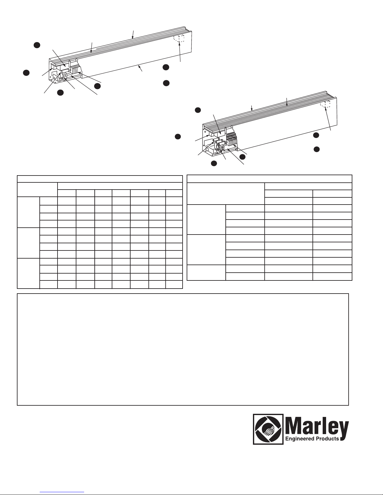
SPECIFICATIONS
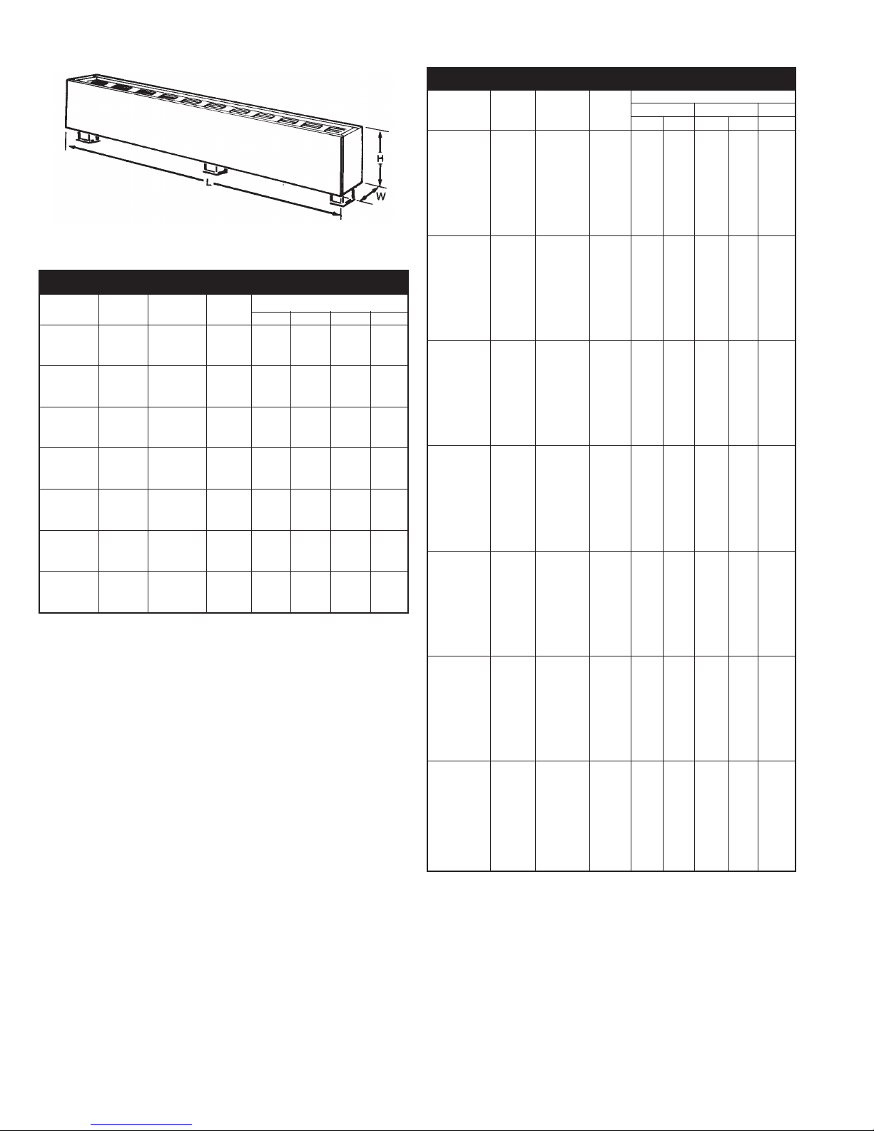
Figure 1
Table A
Model CPLAS (H=5 1/2”; D=3”)
Catalog Length Total Amperage
Number* “L” Watts/Ft. Watts 120V 208V 240V 277V
-2125 125 250 2.4 1.2 1.0 0.9
-2188 28” 188 375 3.1 1.8 1.6 1.4
-2250 250 500 4.2 2.4 2.1 1.8
-3125 125 375 3.1 1.8 1.6 1.4
-3188 3’ 188 564 4.7 2.7 2.4 2.0
-3250 250 750 6.2 3.6 3.1 2.7
-4125 125 500 4.2 2.4 2.1 1.8
-4188 4 188 750 6.2 3.6 3.1 2.7
-4250 250 1000 8.3 4.8 4.2 3.6
-5125 125 625 5.2 3.0 2.6 2.2
-5188 5 188 940 7.8 4.5 3.9 3.4
-5250 250 1250 10.4 6.0 5.2 4.5
-6125 125 750 6.2 3.6 3.1 2.7
-6188 6 188 1125 9.4 5.4 4.7 4.1
-6250 250 1500 12.5 7.2 6.2 5.4
-8125 125 1000 - 4.8 4.2 3.6
-8188 8’ 188 1500 - 7.2 6.2 5.4
-8250 250 2000 - 9.6 8.3 7.2
-10125 125 1250 - 6.0 5.2 4.5
-10188 10’ 188 1875 - 9.0 7.8 6.7
-10250 250 2500 - 12.0 10.4 9.0
* Prefix with: CPLAS
Clearance Chart
For safe and efficient operation, maintain at least the following
Minimum clearances at all times:
Bottom of heater to finished floor
Watts/Ft Heater Length Bottom Inlet Front Inlet
125, 188 and 250 1-3/4” (44 mm) 0” (0 mm)
376 500, 625, and 750 3” (76 mm) 0” (0 mm)
Note:
If pedestals are to be imbedded into floor, see Figure 2a
for minimum exposed dimensions.
Top of heater to bottom of Drapes above heater:
Minimum 12 inches (305 mm)
Important Note:
vinyl blinds) may become damaged by the heated air from the
heater and should not be installed above the heater.
Front of heater to full length drapes in front of heater:
Bottom of drapes and floor - minimum 2 1/2 inches (64 mm)
Top of drapes and ceiling - minimum 1/2 inch (13 mm)
Front of heater and nearest fold of drape - minimum 2 inches
(51 mm)
Certain fabrics and vinyl materials ( such as
Table A (continued)
Model CPLAM (H=7”; D=5”)
Amperage
Catalog Length Total 208V 240V 277V
Number** “L” Watts/Ft Watts 1Ø 3Ø 1Ø 3Ø 1Ø
-2125 125 250 1.2 - 1.0 - 0.9
-2188 188 375 1.8 - 1.6 - 1.4
-2250 250 500 2.4 - 2.1 - 1.8
-2375 28” 375 750 3.6 - 3.1 - 2.7
-2500 500 1000 4.8 - 4.2 - 3.6
-2564 564 1125 5.4 3.1 4.7 2.7 4.0
-2625 625 1250 6.0 3.5 5.2 3.0 4.5
-2750 750 1500 7.2 4.2 6.2 3.6 5.4
-3125 125 375 1.8 - 1.6 - 1.4
-3188 188 564 2.7 - 2.4 - 2.0
-3250 250 750 3.6 - 3.1 - 2.7
-3375 3’ 375 1125 5.4 - 4.7 - 4.0
-3500 500 1500 7.2 - 6.2 - 5.4
-3564 564 1690 8.1 4.7 7.4 4.3 6.1
-3625 625 1875 9.0 5.2 7.8 4.5 6.7
-3750 750 2250 11.0 6.5 9.4 5.4 8.1
-4125 125 500 2.4 - 2.1 - 1.8
-4188 188 750 3.6 - 3.1 - 2.7
-4250 250 1000 4.8 - 4.2 - 3.6
-4375 4’ 375 1500 7.2 - 6.2 - 5.4
-4500 500 2000 9.6 - 8.3 - 7.2
-4564 564 2250 10.8 6.2 9.4 5.4 8.0
-4625 625 2500 12.0 6.9 10.4 6.0 9.0
-4750 750 3000 14.4 8.3 12.5 7.2 10.8
-5125 125 625 3.0 - 2.6 - 2.2
-5188 188 940 4.5 - 3.9 - 3.4
-5250 250 1250 6.0 - 5.2 - 4.5
-5375 5’ 375 1875 9.0 - 7.8 - 6.7
-5500 500 2500 12.0 - 10.4 - 9.0
-5564 564 2820 13.5 7.8 11.8 6.8 10.2
-5625 625 3125 15.0 8.7 13.0 7.5 11.3
-5750 750 3750 18.0 10.4 15.6 9.0 13.5
-6125 125 750 3.6 - 3.1 - 2.7
-6188 188 1125 5.4 - 4.7 - 4.0
-6250 250 1500 7.2 - 6.2 - 5.4
-6375 6’ 375 2250 10.8 - 9.4 - 8.1
-6500 500 3000 14.4 - 12.5 - 10.8
-6564 564 3380 16.2 9.4 14.1 8.1 12.2
-6625 625 3750 18.0 10.4 15.6 9.0 13.5
-6750 750 4500 21.6 12.5 18.7 10.8 16.2
-8125 125 1000 4.8 - 4.2 - 3.6
-8188 188 1500 7.2 - 6.2 - 5.4
-8250 250 2000 9.6 - 8.3 - 7.2
-8375 8’ 375 3000 14.4 - 12.5 - 10.8
-8500 500 4000 19.2 - 16.7 - 14.4
-8564 564 4500 21.6 12.5 18.7 10.8 16.2
-8625 625 5000 24.0 13.9 20.8 12.0 18.0
-8750 750 6000 28.6 16.5 15.0 14.4 21.6
-10125 125 1250 6.0 - 5.2 - 4.5
-10188 188 1875 9.0 - 7.8 - 6.7
-10250 250 2500 12.0 - 10.4 - 9.0
-10375 10’ 375 3750 18.0 - 15.6 - 13.5
-10500 500 5000 24.0 - 20.8 - 18.0
-10564 564 5640 27.2 15.7 23.5 13.6 20.4
-10625 625 6250 30.0 17.3 26.0 15.0 22.6
-10750 750 7500 36.0 20.8 31.3 18.1 27.0
** Prefix with: CPLAM
Top of heater to bottom of window sill:
Minimum 12 inches (305 mm)
2
INSTALLATION INSTRUCTIONS
TO REDUCE THE RISK OF FIRE AND ELECTRIC SHOCK
OR INJURY TO PERSONS, OBS
1. Before installing this heater, remove and discard shipping
pads located within heater. Check to make sure heater is
not damaged.
2. Serious injury or death could result from electric shock.
Make sure electrical power supply circuit coming to heater
is disconnected at main disconnect or service panel before
installing this heater.
3. Wiring procedures and connections must be in accordance
with the National Electrical Code (NEC) and local codes.
Refer to Wiring Diagram on heater and Figure 7. Make sure
all electrical connections are tight to prevent possible overheating. Use Copper Supply Wire Only.
Note:
Supply wiring is to enter heater through one of the
pedestal bases. For pedestal bases not used for wire routing,
covers supplied with pedestal kits must be used.
4. Verify the electrical power supply voltage matches the volt-
age rating as printed on the heater nameplate.
CAUTION - Never connect a heater to a voltage greater than
the nameplate voltage as this will damage the heater and
could cause a fire.
5. Do not install the heater against combustible low-density
cellulose fiberboard surfaces, against or below vinyl wall
coverings, or below any materials that may be damaged by
heat such as vinyl or plastic blinds, curtains, etc. This
heater is supplied with pedestals for floor mounting (supplied in separate carton). See instructions supplied with
pedestal kits.
6. Do not install heater below an electrical convenience recep-
tacle (outlet).
CAUTION
7.
– Heater operates at high temperatures. Keep
electrical cords (including telephone and computer cables),
drapes, and other furnishings away from heater. For efficient and safe operation, we recommend maintaining a minimum of 6 inches (152 mm) clearance above and in front of
the heater at all times.
8. To reduce the risk of fire, do not store or use gasoline or
other flammable vapors or liquids in the vicinity of the
heater.
9. Do not install heater upside down or in any position other
than as shown in this manual. Caution label with word
“TOP” must be at the top when heater is installed.
10. Do not recess heater in wall or install heater inside any type
enclosure as this will cause heater to overheat and could
create a hazard.
11. When mounting heater, use care to secure heater
pedestals to building structure and avoid damaging internal
heater components.
12. Do not remove or bypass the safety limit control (thermal
protector) as this could allow heater to become a fire hazard – see heater wiring diagram supplied with heater.
13. The factory installed wires inside wireway are used to connect the built-in controls. Limit the maximum current to no
more than 45 total amps for CPLAM models (35 amps for
CPLAS models). Refer to instructions and current capacity
rating as provided with the accessory.
14. Heaters that are not installed end to end must have end
caps installed to cover exposed ends of heater.
ERVE THE FOLLOWING:
15. All field wiring brought in to heater must be rated minimum 75°C.
16 Do not allow objects to be placed on top of heater as they
may be damaged or create a fire hazard.
17. Before energizing, make sure that heater is completely
assembled with grille, front cover, end caps and any
accessories installed.
Rough-in Wiring
1. Branch circuits for the heaters shall be enclosed in 1” rigid
conduit for CPLAS, or 1- 1/4” rigid conduit for CPLAM
heaters.
2. Run branch circuit of proper voltage and wire size, in rigid
conduit, to location of left or right junction box as indicated
on heater wiring diagram. Wire entry to heater is through
either end pedestal.
Note:
When pedestal is not used for wire entry, pedestal base
must be covered with cover plate (supplied with pedestal). See
Figure 3.
3. When installing heaters on existing floors, the threaded end
of the rigid conduit must extend 7/8” to 1” above finished
concrete. Conduit must be threaded a minimum of 3/8”.
4. Basic heaters are prewired and can be connected to branch
circuit at either end. Heaters with controls are prewired for
connection to branch circuit at one end only (refer to heater
wiring diagram), however, heater can be wired from opposite
end by running wires through heater wireway.
5. If it is necessary to run wires through the heater wireway,
use Table B to size the field installed wiring.
Table B. Sizing Field Installed Wiring
Copper Maximum no.
wire size of wires Up to 3 4 to 6 7 thru 9
75º C in wireway Conductors Conductors Conductors
No. 12 AWG 9 11.5 amps 9.3 amps 8.1 amps
No. 10 AWG 8 17.4 amps 14.0 amps 12.1 amps
No. 8 AWG 4 24.0 amps 21.0 amps –
Table C. Maximum Length of Heater Run
(CPLAS - 1PH)
Watts/Ft. of Maximum allowable length of heater run (feet)
the heaters 120 Volts 208 Volts 240 Volts 277 Volts
125 33 58 67 77
188 22 38 44 51
250 16 29 33 38
Note:
For mix of watt densities, calculate amp draw. Do not
exceed values indicated in step 6 above.
TABLE D. Maximum Length of Heater Run
(CPLAM - 1PH and 3PH)
Watts/Ft. of Maximum Allowable Length of Heater Run (Feet)
the Heaters 208 Volts 208 Volts 240 Volts 240 Volts 277 Volts
125 74 - 86 - 99
188 49 - 57 - 66
250 37 - 43 - 49
376 24 - 28 - 33
500 18 - 21 - 24
564 16 27 19 32 22
625 14 24 17 29 19
750 12 20 14 24 16
1Ø 3Ø 1Ø` 3Ø 1Ø
Maximum allowable current
3
Thermostat
24 amps @ 120-240 VAC
22 amps @ 277 VAC
Pilot duty– 125 VAC (all voltages)
Transformer relay
CPLAS units: 22 amps @ 120-240 VAC
19 amps @ 277 VAC
CPLAM Units: 25 AMPS @ 120-240 VAC
22 AMPS @ 277 VAC
Power relay
25 amps @ 120-277 VAC- see wiring
diagram on heater
Disconnect switch
20 amps @ 120-277 VAC
Locknut
ousing
H
6. The factory installed wires in the heater wire way can be
loaded up to 35 amps in CPLAS and up to 45 amps in
CPLAM units. Refer to Table C and D for maximum length of
heater run when the heaters are connected in parallel.
7. Standard 75˚C wiring must be used in junction boxes,
wire-
way and blank sections.
Room Layout
Refer to heating plans for exact room arrangements of heaters
(with or without thermostat and/or relays and/or switches and
accessories.)
Heater
Heater Capacity
(Watts.Ft. Heater Length)
125, 188 and 250 Watts/Ft.
376, 500, 564, 625 and 750
Watts/Ft.
Leveling
Nut
Locknut (Do
Not Loosen
Or Remove)
Floor
Line
A
Pedestal
Dimension “A”
(Minimum Mounting
Height Above Floor)
Locknut
1-3/4”
3”
Welded
Bracket
3/8”
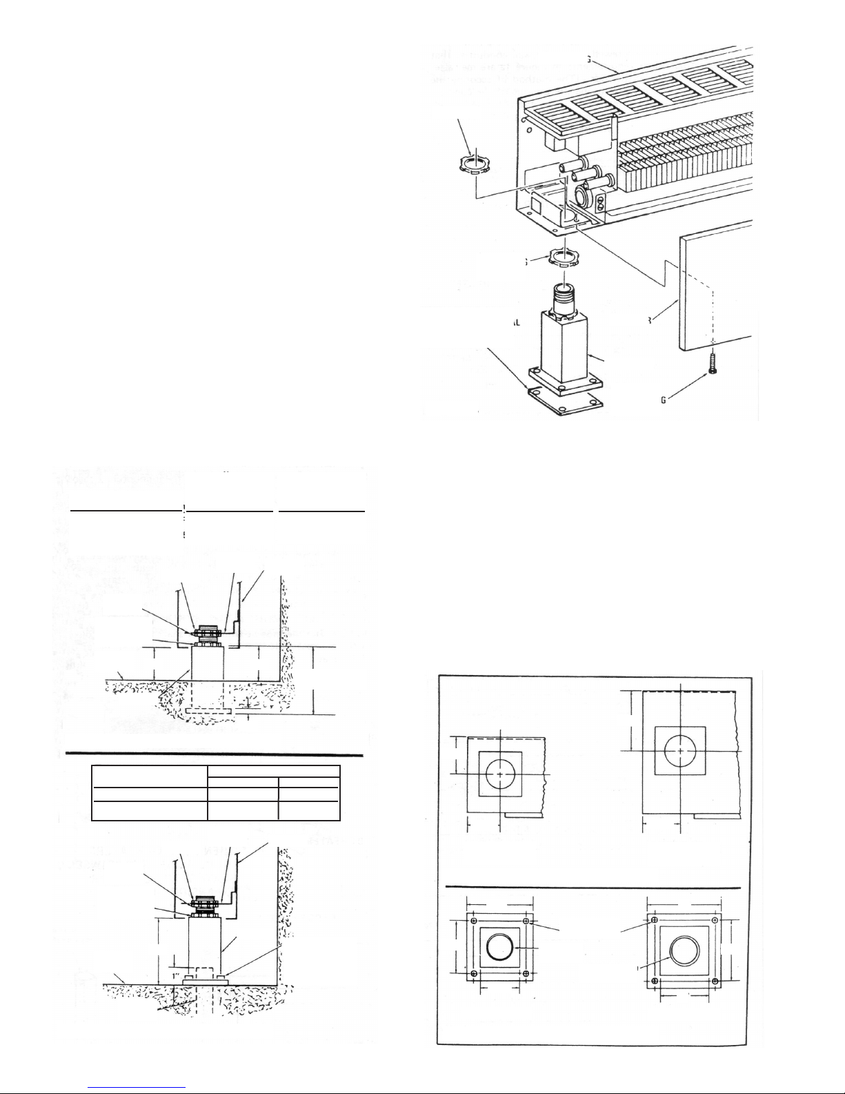
Figure 2a. Pedestal Imbedded in Floor
Heater Catalog Number Height Above Floor (Dim. “A)
CPLAS 2-5/8” 3-3/8”
CPLAM 3-7/8” 4-5/8”
Locknut
Leveling
Nut
Locknut (Do
Not Loosen
Or Remove)
Rigid
Conduit
A
Floor
Line
Min. Max.
Welded
Bracket
Pedestal
Figure 2b. Surface-Mounted Pedestal
B
Pedestal
Dimension “B”
(Minimum Height
Above Floor)
3-1/4”
Heater
2-7/8” (5” Heaters)
4-1/8” (7” Heaters)
Heater
Base Mounting
Holes - 1/4” Da.
(Suitable
Fasteners By
Others)
2”
eveling
L
ut
N
over Plate (Used
C
nly When Pedestal Is
O
ot Used For Wire
N
ntry)
E
Figure 3.
over
C
Pedestal
over
C
ounting
M
crews
S
Mounting Height
Refer to Figure 2a. for typical mounting of heaters and pedestals
imbedded in floor; refer to Figure 2b. for surface-mounted
heaters and pedestals.
Note:
Up to 3/4” thick floor covering, such as carpet, tiles,
linoleum, etc., may be installed around and under the heater.
Pedestal Installation
(Surface-Mounted to Existing Floor)
Note:
For ease of installation, it is important that the sequence
of operations indicated below be followed in order.
1. Remove front cover by removing mounting screws (Fig. 3)
2. Remove the top lock nut and the leveling nut from each
pedestal. (Do not loosen or remove the bottom lock nut.)
2-1/2”
1-7/16”
1-7/16”
Figure 4a. End Pedestal Locations
2.75”
0.250” Dia.
2.125”
1.625”
Mounting Holes
1” Threaded
Pipe
1-1/4” Threaded
Pipe
Figure 4b. Pedestal Details
4
1-9/16”
3”
2.5”
2”

ocknut
L
ooden Jig
W
8”
2
1-7/16” (CPLAS)
1-9/16” (CPLAM)
-7/16” (CPLAS)
1
1-9/16” (CPLAM)
1-7/16” (CPLAS)
1-9/16” (CPLAM)
1-7/16” (CPLAS)
1-9/16” (CPLAM)
edestal
P
ypical Set-Up of Heater
T
edestal Using Jigs To
P
aintain Proper Positioning
M
uring Concrete Pouring.
D
6”
3
33-1/8” (CPLAS)
32-7/8” (CPLAM)
8-13/16”
2
32-13/16”
44-13/16”
60”
3-Foot Heater
7-1/8” (CPLAS)
5
6-7/8” (CPLAM)
5
2”
7
1-9/16” (CPLAM)
69-1/8” (CPLAS)
68-7/8” (CPLAM)
4”
9
1-7/16” (CPLAS)
1-9/16” (CPLAM)
1-7/16” (CPLAS)
5-Foot Heater
93-1/8” (CPLAS)
92-7/8” (CPLAM)
28-Inch Heater
25-1/8” (CPLAS)
24-7/8” (CPLAM)
4-Foot Heater
48”
5-1/8” (CPLAS)
4
4-7/8” (CPLAM)
4
NOTE: HOLES IN JIGS SHOULD BE
1-3/8” FOR CPLAS HEATERS, OR
1-11/16” FOR CPLAM HEATERS.
* WHEN BUTTING HEATERS,
LEAVE A 1/16” GAP BETWEEN
6-Foot Heater
HEATERS TO ALLOW FOR
EXPANSION.
8-Foot Heater
1-7/16” (CPLAS)
1-9/16” (CPLAM)
36-13/16”
76-13/16”
Figure 5.
3. Screw one pedestal onto threaded rigid conduit protruding
from floor.
4. Install remaining pedestal(s) in heater and secure by
installing lock nut finger tight.
5. Install heater onto the pedestal which is screwed on the rigid
conduit. Position heater in desired location and mark
pedestal mounting hole locations on floor. Then remove the
heater and the one pedestal from the rigid conduit.Remove
the remaining pedestal(s) from the heater.
6. Drill holes in floor (Fig. 4b) and install threaded inserts (or
equivalent for 1/4” mounting bolts (inserts and bolts supplied
by installer.)
7. Reinstall the one pedestal on the rigid conduit, then secure
all other pedestals (with cover plates) to the floor with four
1/4” bolts through each pedestal flange.
Pedestal Installation
(Imbedded in New Concrete Floor)
When a heater installation is to be imbedded in a new concrete
floor, the pedestals are first installed in the concrete, then the
heater installed after the concrete has set. It is imperative that
the pedestals be installed in perfect alignment so that the holes
in order to achieve the required alignment, it is recommended
that the pedestals be held in place by the use of jigs during the
concrete pour. The jigs should be constructed of good quality 1”
x 4” lumber as shown in Figure 5. The pedestals are installed in
10-Foot Heater
120”
117-1/8” (CPLAS)
116-7/8” (CPLAM)
End
Cap
Housing
Accessory
Mounting
Holes
Mounting
Screws
End Cap
End Cap Data
Heater Catalog Number
Description CPLAS CPLAM
End Cap Left CPLAS-ECL(R) CPLAM-ECL(R)
End Cap Right CPLAS-ECR(R) ASH07-ECL(R)
(R) Suffix on catalog number refers to accessories with 120 VAC receptacle.
Figure 6.
5

the jigs and then positioned for the concrete pour. One end
pedestal must be screwed onto rigid wall conduit so that the
mounting height requirements in Figure 1a are met after pouring
of the finished floor. (The method of securing the pedestals and
jigs in place during the pouring of the concrete is at the option of
the installer.) After the concrete has set, remove the jigs from
the pedestals and install the heater as indicated in steps Seven
or Eight.
Installation of Single Unit
Note:
For ease of installation, it is important that the sequence
of operations below be followed in order.
1. Remove front cover by removing mounting screws (Fig. 3)
2. Install end caps (must be purchased separately) on both
ends of the heater housing. Refer to Figure 6 for details of
end cap installation.
3. Install leveling nut on each installed pedestal, then position
heater on pedestals. Adjust the leveling nuts until the heater
is level and at the desired mounting height. Then install and
tighten the pedestal lock nuts.
4. Run proper size branch circuit to the junction box through the
appropriate end pedestal.
5. Following the wiring diagram secured to the heater, make
electrical connections.
6. Replace front cover and secure with mounting screws. (See
Figure 3.)
7. If the heater is equipped with a built-in thermostat, adjust the
shaft to the mid-range and let the heater run for a few hours.
If the room temperature is too hot, rotate the shaft counterclockwise; if too cool, rotate the shaft clockwise until a comfortable temperature is obtained. Let room temperature stabilize after each setting change. The heater will automatically cycle around this set point on the thermostat.
Note:
If a thermostat or disconnect switch is provided in the
heater, these components are accessible through the grille
openings at the left or right end of the heater.
Installation of Multiple Units
Note:
For ease of installation, it is important that the sequence
of operations indicated below be followed in order.
1. Remove front cover by removing mounting screws (Figure
3.)
2. Install end caps on the outer end of the first and last heater
(or blank section ) in a run using four No. 6 screws supplied
with end caps. (Refer to Figure 6 for details of end cap
installation.)
3. Run proper size branch circuit to the junction box through
heaters and blank sections (if applicable) on pedestals.
Note
: When butting heaters end to end, be sure to position
heaters carefully to insure proper alignment. Leave a 1/16” gap
between heaters to allow for expansion.
4. Adjust the leveling nuts until the heaters are level and at the
desired mounting height. Then install and tighten the
pedestal lock nuts.
Note
: 75˚C field wiring may be run through the blank section
wireway.
5. Following the wiring diagram secured to the heater, make the
electrical connections. Refer to Figure 7 to connect the other
heaters in parallel. Grounding of the other heaters is accomplished by connecting a jumper wire (not supplied) between
the two adjacent heaters.
6. Replace front covers, and secure with mounting screws.
(Figure 3.)
OPERATION INSTRUCTIONS
1. This heater must be properly installed before it is used.
2. If the heater is equipped with a built-in thermostat, adjust the
shaft to the mid-range and let the heater run for a few hours.
If the room temperature is too hot, rotate the shaft counterclockwise; if too cool, rotate the shaft clockwise until a comfortable temperature is obtained. Let room temperature stabilize after each setting change. The heater will automatically cycle around this set point on the thermostat.
Note:
If a thermostat or disconnect switch is provided in the
heater, these components are accessible through the grille
openings at the left or right end of the heater.
MAINTENANCE INSTRUCTIONS
For efficient and safe operation and to extend the life of the
heaters, they should be cleaned and inspected for damage at
least annually (preferably at the beginning of the heater season)
or more often in dirty environments. Other than cleaning, your
heaters require no other preventative maintenance.
1. Serious injury or death could result from electric shock.
Make sure electrical power supply circuit(s) coming to
heater is/are disconnected at main disconnect or service
panel before servicing this heater. Allow heater to cool
before cleaning to prevent a possible burn.
NOTE:
sure all power is disconnected to heater before cleaning or
servicing.
2. Use care when cleaning element fins to avoid damaging
1. The user can perform periodic cleaning of the outer cabinet.
2. Heater cabinet may be cleaned using a damp cloth to
4. A vacuum cleaner and/or compressed air may be used to
5. After cleaning and servicing, always reassemble replacing
Important Note:
the heaters including one or more over-temperature limit controls (Thermal Protector) - see Wiring Diagram on heater for
specific controls provided. These safety controls are provided to
cycle the heater off to maintain safe temperatures in the event of
a blockage or other abnormal condition. DO NOT remove or
bypass these important safety controls as they are provided to
limit the temperatures and prevent a possible fire in the event
the heater is subjected to an overheating condition. If it is determined that the heater is cycling off on the safety controls during
normal use, discontinue using the heater until it can be
inspected and repaired by a qualified service personnel.
More than one power source may enter heater. Be
fins. Note also that fins are sharp and may cause cuts so
avoid contact.
All other servicing is to be done by qualified service personnel.
remove dust that may have accumulated on surfaces. Do not
use harsh cleaners or waxes on surfaces since these could
damage the finish or discolor in use.
remove dust and lint that may have accumulated inside
heater around element fins. If heater must be disassembled
for cleaning, use care not to bend or damage the aluminum
fins.
any hardware removed, restore power and check to make
sure the heaters are operating properly
There are built-in safety devices provided within
6
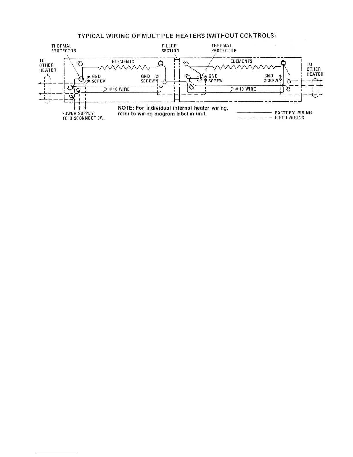
Figure 7 - Wiring Diagram
7
6
3
2
1
4
5
GRILLE
2501-0253-VAR
B
ACK PANEL
2
701-0765-VAR
FRONT COVER
1
402-0316-VAR
H
EATING
ELEMENT
WIREWAY COVER
6
405-0053-VAR
O
VERLOAD
PROTECTOR
4
520-0007-VAR
POWER RELAY
(
OPTIONAL)
T
RANSFORMER
R
ELAY
(OPTIONAL)
ELEMENT BUSHING
1
213-2000-001
DISCONNECT
SWITCH
(OPTIONAL)
T
HERMOSTAT
(OPTIONAL)
6
3
2
1
4
5
GRILLE
2501-0254-VAR
BACK PANEL
2
701-0766-VAR
FRONT COVER
1402-0315-VAR
HEATING
ELEMENT
WIREWAY COVER
6405-0053-VAR
OVER LOAD
PROTECTOR
4520-0007-VAR
POWER RELAY
(OPTIONAL)
TRANSFORMER
RELAY
(OPTIONAL)
ELEMENT BUSHING
1213-2000-001
DISCONNECT
SWITCH
(OPTIONAL)
THERMOSTAT
(OPTIONAL)
Heating Element (Part No. Prefix 1802-2001)
Description Heater Length
28” 3’ 4’ 5’ 6’ 8’ 10’
25W/Ft. 120V 085 087 089 091 093 --
1
er 208V 086 088 090 092 094 095 096
p
Element 240V 048 054 060 066 072 077 081
277V 049 055 061 067 073 078 082
188 W/Ft. 120V 005 011 017 023 029 --
per 208V 002 008 014 020 026 032 036
Element 240V 001 007 013 019 025 031 035
277V 000 006 012 018 024 030 034
250W/Ft. 120V 004 010 016 022 028 --
per 208V 003 009 015 021 027 033 037
Element 240V 002 008 014 020 026 032 036
277V 001 007 013 019 025 031 035
Built-In Controls (Optional)
escription Part Number
D
PLAM CPLAS
C
Disconnect Switch 5216-0125-000 5216-0124-000
Transformer 120 Volt R13700002B001 410043001
Relay 208 Volt R13700002B002 410043002
240 Volt R13700002B003 410043003
277 Volt R13700002B004 410043004
Power 24 Volt 5018-2006-000 5018-2006-000
Relay 120 Volt 5018-2006-001 5018-2006-001
208/240 Volt 5018-2006-002 5018-2006-002
277 Volt 5018-2006-003 5018-2006-003
Thermostat 1 Pole 5813-0024-000 5813-0024-000
2 Pole 5813-0023-000 5813-0023-000
All products manufactured by Marley Engineered Products are warranted against defects in workmanship and materials for one year from date of installation, except
LIMITED WARRANTY
heating elements which are warranted against defects in workmanship and materials for five years from date of installation. This warranty does not apply to damage from
accident, misuse, or alteration; nor where the connected voltage is more than 5% above the nameplate voltage; nor to equipment improperly installed or wired or
maintained in violation of the product’s installation instructions. All claims for warranty work must be accompanied by proof of the date of installation.
The customer shall be responsible for all costs incurred in the removal or reinstallation of products, including labor costs, and shipping costs incurred to return products
to Marley Engineered Products Service Center. Within the limitations of this warranty, inoperative units should be returned to the nearest Marley authorized service center or the Marley Engineered Products Service Center, and we will repair or replace, at our option, at no charge to you with return freight paid by Marley. It is agreed that
such repair or replacement is the exclusive remedy available from Marley Engineered Products.
THE ABOVE WARRANTIES ARE IN LIEU OF ALL OTHER WARRANTIES EXPRESSED OR IMPLIED, AND ALL IMPLIED WARRANTIES OF MERCHANTABILITY AND
FITNESS FOR A PARTICULAR PURPOSE WHICH EXCEED THE AFORESAID EXPRESSED WARRANTIES ARE HEREBY DISCLAIMED AND EXCLUDED FROM
THIS AGREEMENT. MARLEY ENGINEERED PRODUCTS SHALL NOT BE LIABLE FOR CONSEQUENTIAL DAMAGES ARISING WITH RESPECT TO THE
PRODUCT, WHETHER BASED UPON NEGLIGENCE, TORT, STRICT LIABILITY, OR CONTRACT.
Some states do not allow the exclusion or limitation of incidental or consequential damages, so the above exclusion or limitation may not apply to you. This warranty gives
you specific legal rights, and you may also have other rights which vary from state to state.
For the address of your nearest authorized service center, contact Marley Engineered Products in Bennettsville, SC, at 1-800-642-4328. Merchandise returned to the factory must be accompanied by a return authorization and service identification tag, both available from Marley Engineered Products. When requesting return authorization,
include all catalog numbers shown on the products.
HOW TO OBTAIN WARRANTY SERVICE AND
WARRANTY PARTS PLUS GENERAL INFORMATION
1. Warranty Service or Parts
2. Purchase Replacement Parts
3. General Product Information
Note:
When obtaining service always have the following:
1. Model number of the product
2. Date of manufacture
3. Part number or description
Part No. 5200-2211-001
1-800-642-4328
1-800-654-3545
www.marleymep.com
ECR 38636
01/11
470 Beauty Spot Rd. East
Bennettsville, SC 29512 USA
 Loading...