

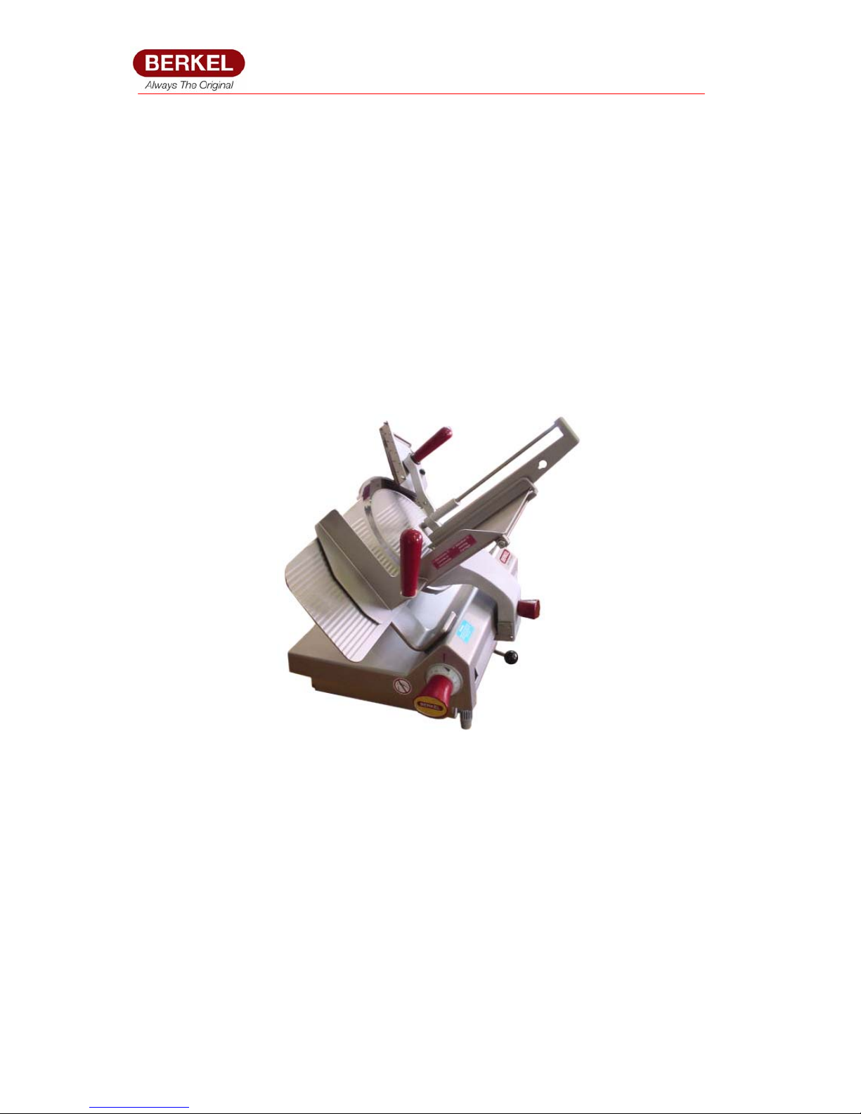
Berkel 932, 933 Service Manual
900 Series 932-933 Date 11-06-08 SM - Code SC1- Rev. 0.1
Service Manual
SERVICE MANUAL
932 & 933
SEMI AUTOMATIC SLICERS

900 Series 932-933 Date 11-06-08 SM - Code SC1- Rev. 0.1
2
Service Manual
CONTENTS
Table of Contents:
1 INTRODUCTION
2 SAFETY
3 ELECTRICAL DIAGRAMS
4 TECHNICAL INFORMATION
5 APPENDICES

900 Series 932-933 Date 11-06-08 SM - Code SC1- Rev. 0.1
3
Service Manual
1 INTRODUCTION
Table of Contents:
1.0 INTRODUCTION
The Berkel 932 and 933 slicers are stainless steel robust slicers designed for
continuous use, these slicers are IP33 rated.
The slicers have a simple electronic control and are easy to operate.
The carriage can be moved either automatically or manually.
2 SAFETY
Table of Contents:
2.0 SAFETY
Page
2.1 Safety devices 4
2.2 Products that can’t be sliced 4
CAUTION! ALWAYS READ AND FULLY UNDERSTAND THE USER
INSTRUCTIONS BEFORE OPERATING THIS EQUIPMENT
900 Series 932-933 Date 11-06-08 SM - Code SC1- Rev. 0.1
4
Service Manual
2.1 Safety devices
The machine will not self start after a voltage drop
Fixed metal ring around the blade which is non removable
The thickness plate is locked when the carriage is tilted.
Emergency switch ‘OFF’ button (See below)
2.2 Products that can’t be sliced
Non food items
Food with bones
Deep frozen food products
Note: To slice quantities of cheese the Teflon coated option is recommended
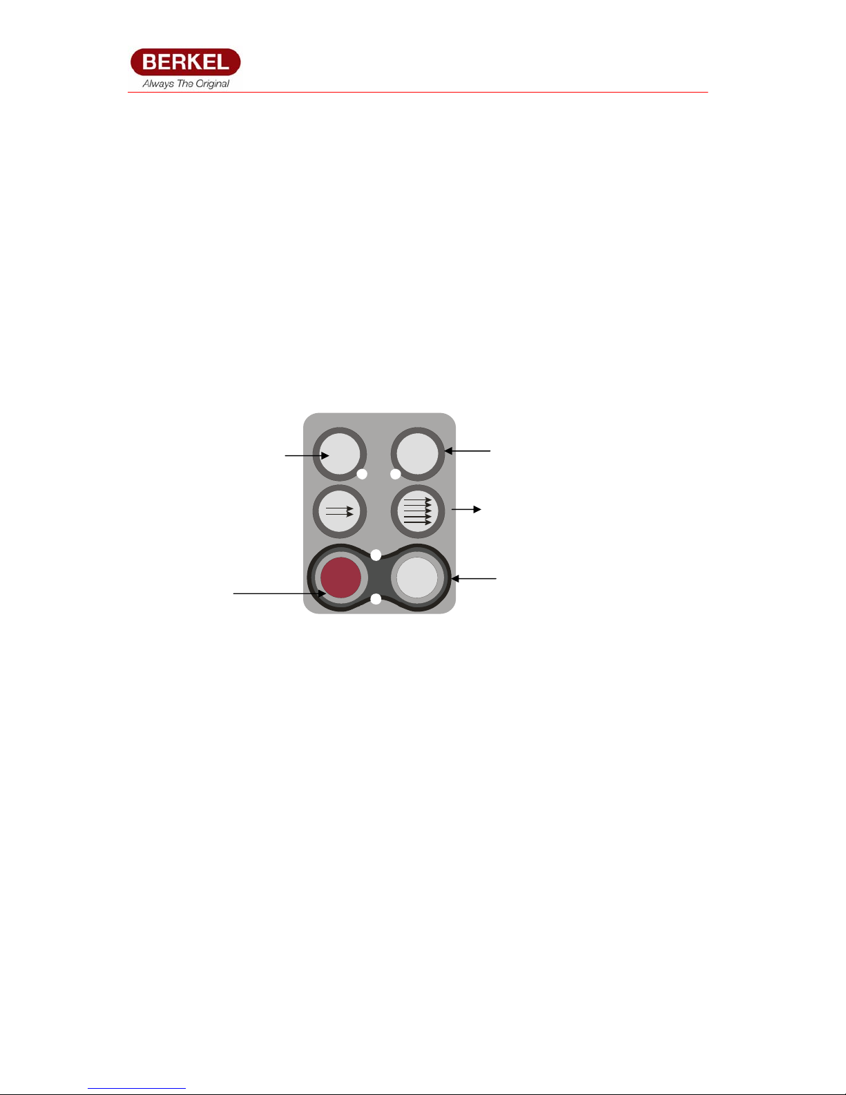
O
I
0
manual
0 / I
> 1 sec
Automatic
I
Emergency OFF
button
Switch ON to
standb
y
Manual – knife runs
only when held down
for > 1 second. Or
Auto carriage switch
OFF
Automatic carriage
turn ON
Carriage speed decrease /
increase buttons: From 32 to
52 table strokes / min in

900 Series 932-933 Date 11-06-08 SM - Code SC1- Rev. 0.1
5
Service Manual
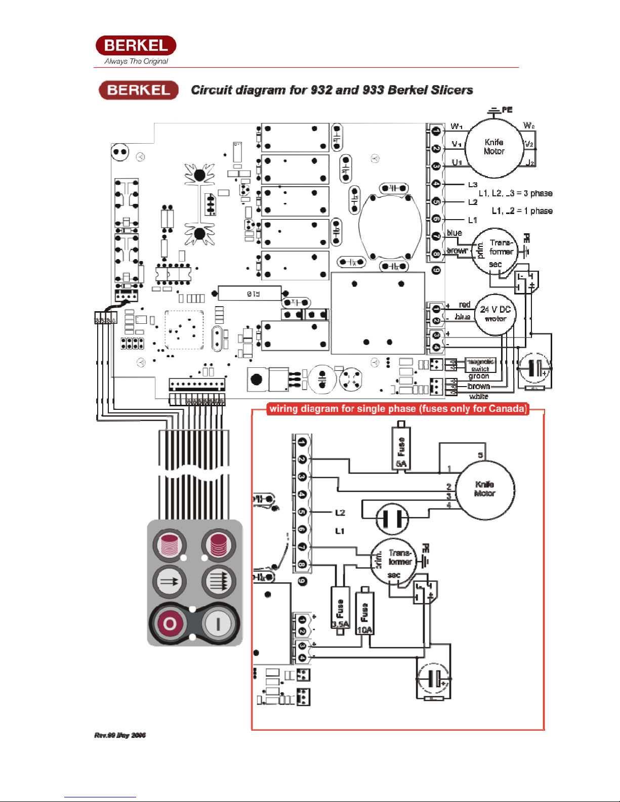
3 ELECTRICAL DIAGRAMS
Table of Contents:
Page
3.0 ELECTRICAL DIAGRAM 6
900 Series 932-933 Date 11-06-08 SM - Code SC1- Rev. 0.1
6
Service Manual

900 Series 932-933 Date 11-06-08 SM - Code SC1- Rev. 0.1
7
Service Manual
4 TECHNICAL INFORMATION
Table of Contents:
Page
4.1 TECHNICAL DATA 8
4.2 MAINTENANCE 9
900 Series 932-933 Date 11-06-08 SM - Code SC1- Rev. 0.1
8
Service Manual
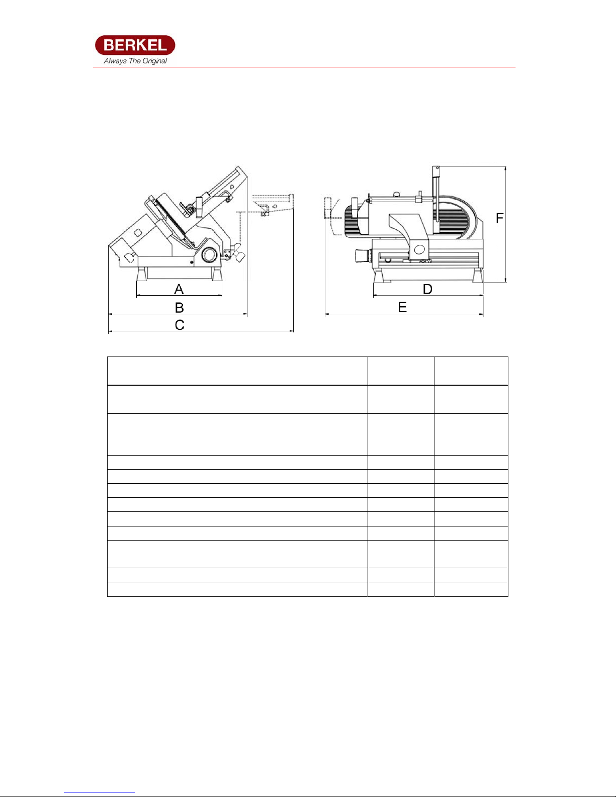
4.1 TECHNICAL DATA
MODELS BERKEL
932
BERKEL
933
KNIFE DIAMETER: mm
: inches (approximate)
330
13
350
14
CUTTING CAPACITY: Rectangular
mm : Round
320 x
220h
220
320 x 235h
235
Maximum slice thickness mm 25 25
Dimension: M 680 680
Overall Dimension: L 1000 1000
Overall Dimension: F 950 950
Footprint Dimension: D 480 480
Footprint Dimension: A 390 390
Maximum distance between the pusher and
gauge plate
300 300
Speed of table 32 - 52 32 - 52
Motor power rating 1 PHASE 0.6kW 0.6kW

900 Series 932-933 Date 11-06-08 SM - Code SC1- Rev. 0.1
9
Service Manual
4.2 MAINTENANCE
SERVICE CHECKLIST
1 Ensure that when the index knob is set to zero that the knife is safe –
not exposed.
2 Check all interlocks whether mechanical or electrical function
correctly.
3 Check that all safety guards are in place, are fitted correctly and are
not damaged
4 Check all moving parts and lubricate where necessary
5 Ensure the knife is sharp
6 Remove the knife using the customers knife remover and check for
safety also check condition of knife screws and knife bearing
7 Check drive belt and re-tension or replace if necessary and check
tension of chain drive for carriage and tension if required
8 Visually check the electrical components of the machine including the
mains lead & plug, keypad etc…
9 Check the wear on the knife has not exceeded a gap between the
knife and finger guard of 6mm.
10 If necessary move the gauge plate up to the knife edge as per factory
setting
11 Liaise with the customer to see if they have noticed any problems
12 Clean any sharpening dust off the machine and ask the customer to
check the first slice just in case!
If you find any hazardous problems with the machine i.e. interlock not functioning
then inform the customer that the machine is not safe to be used and note the issue
on your TJR.

900 Series 932-933 Date 11-06-08 SM - Code SC1- Rev. 0.1
10
Service Manual
5 APPENDICES
Table of Contents:
Page
5.1 OPTIONS 10
5.2 RECOMMENDED PARTS 10
5.3 EXPLODED VIEWS WITH PARTS LISTINGS 11
5.1 OPTIONS
Teflon coating on knife, gauge plate, centre plate and meat table top
Top clamp meat table
5.2 TECHNICIANS RECOMMENDED PARTS
PART NUMBER DESCRIPTION QTY
B9S-2.24 Countersunk screw (Knife screw) 4
B92-009-014 Sharpener stone - fine 2
B92-2.6 Blade 330mm, 932 1
B93-2.6 Blade 350mm, 933 1
BS936-312 Knife remover 330mm 1
G350-313 Knife remover 350mm 1
B9S-52.32 Switch foil 1

900 Series 932-933 Date 11-06-08 SM - Code SC1- Rev. 0.1
11
Service Manual
5.3 EXPLODED VIEWS AND PART NUMBERS
Page
5.3.1 932/933 Machine body (Drawing 1) 12
5.3.2 932/933 Blade drive unit (Drawing 2) 14
5.3.3 932/933 Knife hub (Drawing 3) 16
5.3.4 932/933 Thickness plate complete with support (Drawing 4) 18
5.3.5 932/933 Index knob and cam assembly (Drawing 5) 20
5.3.6 932/933 Meat table and support (Drawing 6) 22
5.3.7 932/933 End piece holder assembly (Drawing 7) 24
5.3.8 932/933 Product fence (Drawing 8) 26
5.3.9 932/933 Sliding carriage support (Drawing 9) 28
5.3.10 932/933 Electrical components (Drawing 10) 30
5.3.11 932/933 Carriage chain drive (Drawing 11) 32
5.3.12 932/933 Chain cog assembly (Drawing 12) 34
5.3.13 932/933 Plate for sliding support (Drawing 13) 36
5.3.14 932/933 Auto / manual lever (Drawing 14) 38
5.3.15 932/933 Electronic PCB & Transformer (Drawing 15) 40
5.3.16 Additional Parts 42
900 Series 932-933 Date 11-06-08 SM - Code SC1- Rev. 0.1
Service Manual
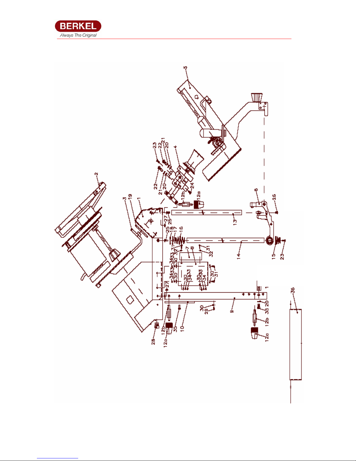
5.3.1 932 / 933 Machine body (Drawing 1)

900 Series 932-933 Date 11-06-08 SM - Code SC1- Rev. 0.1
13
Service Manual
5.3.1 932 / 933 Machine Body (Drawing 1)
REF PART NO DESCRIPTION
1 B9S-1 Machine Body Complete
2 B92-2 Blade drive unit complete assembly (drawing 2)
B93-2 Blade drive unit complete assembly (drawing 2)
3 B92-3 Thickness plate complete with support (drawing 4)
B93-3 Thickness plate complete with support (drawing 4)
4 B9S-4 Adjusting lever complete assy (Drawing 5)
5 B9S-5 Carriage complete assy (drawing 6)
6 B9S-6 Sliding support complete assy (drawing (9)
7 B9S-7 Electric complete assy ( drawing 10)
8 B9S-8 Fixing plate for electric components
9 B9S-9 Fixing bar for feet
10 B9S-10 Cover sheet for motor Distance piece for fixing bar
11 B9S-11 Distance piece for fixing bar
12a B9S-12a Foot
12b B9S-12b Distance piece for foot
13 B9S-13 Guiding shaft for carriage support. Short
14 B9S-14 Guiding shaft for carriage support
15 B9S-15 Conical pressure spring
16 B9S-16 Double conical pressure spring
17 B9S-17 Washer
18 B9S-18 Stop ring
19 B9S-19 Sealing
20 B9S-20 Washer
21 B9S-21 Spring washer
22 B9S-22 Cylindrical screw
23 B9S-23 Countersunk screw
24 B9S-24 Hexagon screw
25 B9S-25 Cup screw
26 B9S-26 Countersunk screw
27 B9S-27 Hexagon nut with flange
28 B9S-28 Strain relief
29 B9S-29 Lens head screw
30 B9S-30 Washer
31 B9S-31 Cylindrical screw
32 B9S-32 Washer
33 B9S-33 Toothed disk
34 B9S-34 Hexagon nut
35 B9S-35 Cylindrical screw
36 B9S-36 Bottom plate
 Loading...