

Page 1

EN
Table lift hood
BTHMoveline
EN
Operating and installation instructions for the models
BTH 100 ML
6004067_a
Page 2
Document information
Operating and installation instructions for:
y Table lift hood BTH 100 ML E01
Descriptions are identical for all variants.
Differences are noted separately.
Illustrations show:
y Example installation “in a cabinet”.
y Original instructions.
y Part of the product.
y Copyright protected.
y Duplications, re-printing and distribution only with
permission.
y Subject to alteration.
Safety information
D DANGER!
Notes with the word DANGER warn of a hazardous situation
that results in serious injuries or death.
Symbol clarification - text
☞ Handling requirement
y Listing
D Reference to another point in this document
Reference to other documents that should be observed
Symbol clarification - illustrations
A
x
1.
B
2.
D WARNING!
Notes with the word WARNING warn of a hazardous situation
that could result in serious injuries or death.
D CAUTION!
Notes with the word CAUTION warn of a situation that could
result in minor injuries.
D ATTENTION!
Notes with the word ATTENTION warn of a situation that
could result in damage to property or to the environment.
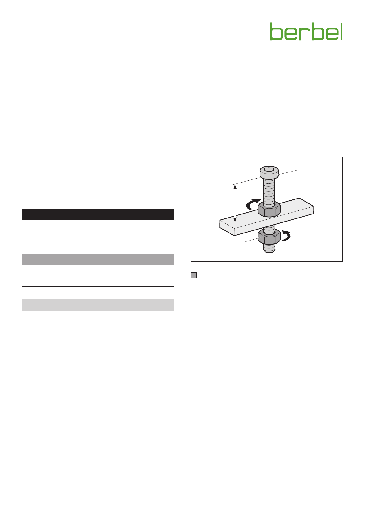
Highlighting of the parts involved in the action with
shading
1. Handling steps with numbering
A Part designations with upper case characters
x Dimensions with lower case characters or units in mm
Movement and direction arrows
2
6004067_a – 01.08.2018
Page 3

Table of contents
1. Safety information ............................ 4
1.1 Proper intended use . . . . . . . . . . . . . . . . . . . . . 4
1.2 Authorised target groups. . . . . . . . . . . . . . . . . . 4
1.3 General safety instructions . . . . . . . . . . . . . . . . . 4
2. Product information ........................... 5
2.1 Functional principle . . . . . . . . . . . . . . . . . . . . . 5
2.2 Operating modes. . . . . . . . . . . . . . . . . . . . . . . 5
2.2.1 Recirculated air mode .........................5
2.2.2 Extracted air mode ............................5
2.2.3 Hybrid mode ..................................5
2.3 Product overview . . . . . . . . . . . . . . . . . . . . . . . 6
2.4 Example installations. . . . . . . . . . . . . . . . . . . . . 6
2.4.1 Example installation “in a cabinet
(recirculated air mode)” ........................6
2.4.2 Example installation “cabinet rear
(recirculated air mode)” ........................6
2.4.3 Example installation “island (extracted air
mode)” ........................................6
2.5 Scope of delivery . . . . . . . . . . . . . . . . . . . . . . . 7
2.6 Installation dimensions . . . . . . . . . . . . . . . . . . . 7
2.7 Technical data . . . . . . . . . . . . . . . . . . . . . . . . . 8
5. Cleaning ..................................... 26
5.1 Safety information for cleaning . . . . . . . . . . . . . .26
5.2 Cleaning procedures. . . . . . . . . . . . . . . . . . . . .26
6. Maintenance .................................28
6.1 Safety information for maintenance . . . . . . . . . . .28
6.2 Maintenance. . . . . . . . . . . . . . . . . . . . . . . . . .28
6.2.1 Changing the lamps ........................28
6.2.2 Replacing filter filing (with recirculating
and hybrid mode) ........................... 28
6.3 Fault rectification . . . . . . . . . . . . . . . . . . . . . . .30
7. Dismounting ................................. 31
8. Disposal ...................................... 32
8.1 Dispose of packaging . . . . . . . . . . . . . . . . . . . .32
8.2 Dispose of the device . . . . . . . . . . . . . . . . . . . .32
9. Annex ........................................ 33
9.1 Product data sheet . . . . . . . . . . . . . . . . . . . . . .33
9.2 Accessories. . . . . . . . . . . . . . . . . . . . . . . . . . .34
9.3 Contact . . . . . . . . . . . . . . . . . . . . . . . . . . . . .34
3. Installation .................................... 9
3.1 Safety information for installation. . . . . . . . . . . . . 9
3.2 Requirements for the installation location . . . . . . . 9
3.3 Requirements for individual operating modes. . . . .10
3.3.1 Requirements for recirculated air mode ..... 10
3.3.2 Requirements for extracted air mode ........ 10
3.3.3 Requirements for hybrid mode .............. 10
3.4 Requirements for the exhaust air ducting
(only for extracted air mode or hybrid mode) . . . . .10
3.5 Installation procedure . . . . . . . . . . . . . . . . . . . .11
3.5.1 Preparation for installation ..................11
3.5.2 Unpack the device ..........................11
3.5.3 Check dimensions .......................... 12
3.5.4 Move fan box (optional) ..................... 13
3.5.5 Install filter (with recirculating or hybrid
operation) ..................................15
3.5.6 Install the device ............................ 16
3.5.7 Install the hob .............................. 19
3.5.8 Connect accessories ........................ 19
3.5.9 Connect exhaust air ducting (with
exhausted air or hybrid operation) ..........20
3.5.10 Establish electrical power supply ............21
3.5.11 Check and carry out commissioning ........21
4. Operation ....................................22
4.1 Safety information for operation . . . . . . . . . . . . .22
4.2 Control panel . . . . . . . . . . . . . . . . . . . . . . . . .23
4.3 Normal operation. . . . . . . . . . . . . . . . . . . . . . .23
4.3.1 Run-on function ............................ 24
4.3.2 Extraction mode / recirculated air mode
changeover .................................24
4.3.3 Check filter filling indicator ..................25
4.4 Configuration . . . . . . . . . . . . . . . . . . . . . . . . .25
EN
6004067_a – 01.08.2018
3
Page 4

Safety information
1. Safety information
1.1 Proper intended use
The device serves to extract cooking vapours during cooking
with electrically operated hobs.
The device is intended exclusively for private domestic use.
The device must only be used with original filters from the
manufacturer.
It is only permitted to use the device when it is in technically
flawless condition and after correct installation.
Any other use shall be considered improper use.
The reading and observance of this manual are also included
in the proper use of the device.
1.2 Authorised target groups
Electrical work only to be undertaken by qualified electricians
in accordance with DIN VDE 0100. Requirements on qualified
electricians:
y Knowledge of the basics of electrics.
y Knowledge of country-specific regulations and standards
(e.g. in Germany, DIN VDE 0100, part 701).
y Knowledge of the applicable safety regulations.
y Knowledge of the relevant legal requirements for gas
installations (e.g. in Germany the technical rules for gas
installations TRGI).
y Knowledge of this manual.
Installation and repair only by qualified specialist personnel.
Requirements on qualified specialist personnel:
y Knowledge of the regulations on safety at work.
y Knowledge of fastening systems.
y Basic knowledge of ventilation systems.
y Experienced in using electrical and mechanical tools.
y Ability to read technical drawings.
y Knowledge of this manual.
Operation, cleaning and maintenance by the user.
Requirements for the user:
y Knowledge of this manual.
1.3 General safety instructions
D WARNING!
Hazard through a disregard of the operating and
installation instructions!
This manual contains important information for the safe
handling of the device. Separate reference is made to
possible hazards.
☞ Read through this manual thoroughly.
☞ Follow the safety instructions in this manual.
☞ Store the manual in an accessible location.
Naked flames can damage the device and can cause fires.
y Do not flambé near the device.
y No unattended deep frying near the device.
The use of the device is forbidden under the following
circumstances:
y With the usage of gas hobs.
y If necessary safety devices are missing
(e.g. low-pressure monitor whilst using a heating point
which uses air from the room as its oxygen supply).
y If essential approvals are missing (e.g. from
chimneysweeps).
y In potentially explosive atmospheres.
y If the device or individual components are damaged.
y In the event of unauthorised alterations or changes to the
device.
y If liquid has penetrated the device.
y When heavily soiled.
y For children under 8 years old and persons who would
not be able to properly assess the hazards associated with
handling the device.
The manufacturer accepts no liability for damage occurring in
the following circumstances:
y Disregard of this manual.
y Improper use of the device.
y Improper installation and handling of the device.
y Use of the device by unauthorised target groups.
y Bypassing safety equipment on the device.
y Use of replacement parts that were not produced or
approved by the manufacturer.
There are separate requirements for the following users:
y Children from 8 years and older.
y Persons with restricted physical, sensory or mental
capabilities.
y Persons with a lack of experience and knowledge.
These users are only permitted to carry out operation,
cleaning and maintenance. Special requirements:
y Users are supervised.
y Users are instructed with regard to safe use of the device.
y Users understand the hazards involved with the device.
y Children may not play with the device.
4
Further safety instructions can be found in the respective
relevant chapter of this manual.
D “3.1 Safety information for installation” (page 9).
D “4.1 Safety information for operation” (page 22).
D “5.1 Safety information for cleaning” (page 26).
D “6.1 Safety information for maintenance” (page 28).
6004067_a – 01.08.2018
Page 5
Product information
2. Product information
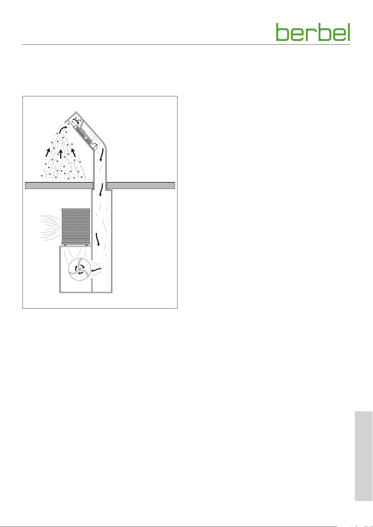
2.1 Functional principle
2.2 Operating modes
The device is suitable for the following operating modes:
y Recirculated air mode
y Extracted air mode
y Hybrid mode
2.2.1 Recirculated air mode
The filter filling in the recirculated air filter neutralises any
smelly odours present. The odour-free, cleaned room air is
fed back into the room. The humidity in the room can be
reduced with the fresh air feed.
In recirculated air mode, it is necessary to use the run-on
function so that the device can remove the remaining
odours. Using the run-on function increases the life of the
filter filling. The filter filling must be replaced at regular
intervals.
2.2.2 Extracted air mode
The cleaned room air can be routed to the outside via the
building structure (e.g. ducting, chimney).
Centrifugal force
y Cooking vapours are drawn through a gap and into the
hood where they are accelerated and routed through
bends.
y The resultant centrifugal force ejects particles of dirt
(e.g. particles or grease and oil) out of the air.
y The dirt particles are separated out and collected on the
bulging edge, on the upper and lower section as well as a
catchment screen (“Capillar Trap”).
Back-flow technology
y Condensate or droplet formation (e.g. if steam touches
the cold surface) is prevented by a vent installed from the
bottom to the top.
y Part of the vented air quantity is fed back inside the hood,
blown in via the opening slit and directed into the suction
gap.
With extracted air mode an adequate fresh air supply is
required. The device can only extract the amount of air to the
outside that is present in the room or which is drawn into the
room.
2.2.3 Hybrid mode
In hybrid mode, it is possible to select flexibly between
recirculated air mode and extracted air mode.
In extracted air mode, the cleaned room air is routed to the
outside through the wall box which opens automatically.
Extracted air mode is recommended in summer or with
particularly intensive frying.
In recirculated air mode the wall box remains closed. The
filter filling in the hybrid filter neutralises any smelly odours
present. The odour-free, cleaned room air is fed back into the
room.
The recirculated air mode is recommended in winter if no
warm room air is to be surrendered to the outside.
EN
6004067_a – 01.08.2018
5
Page 6
Product information
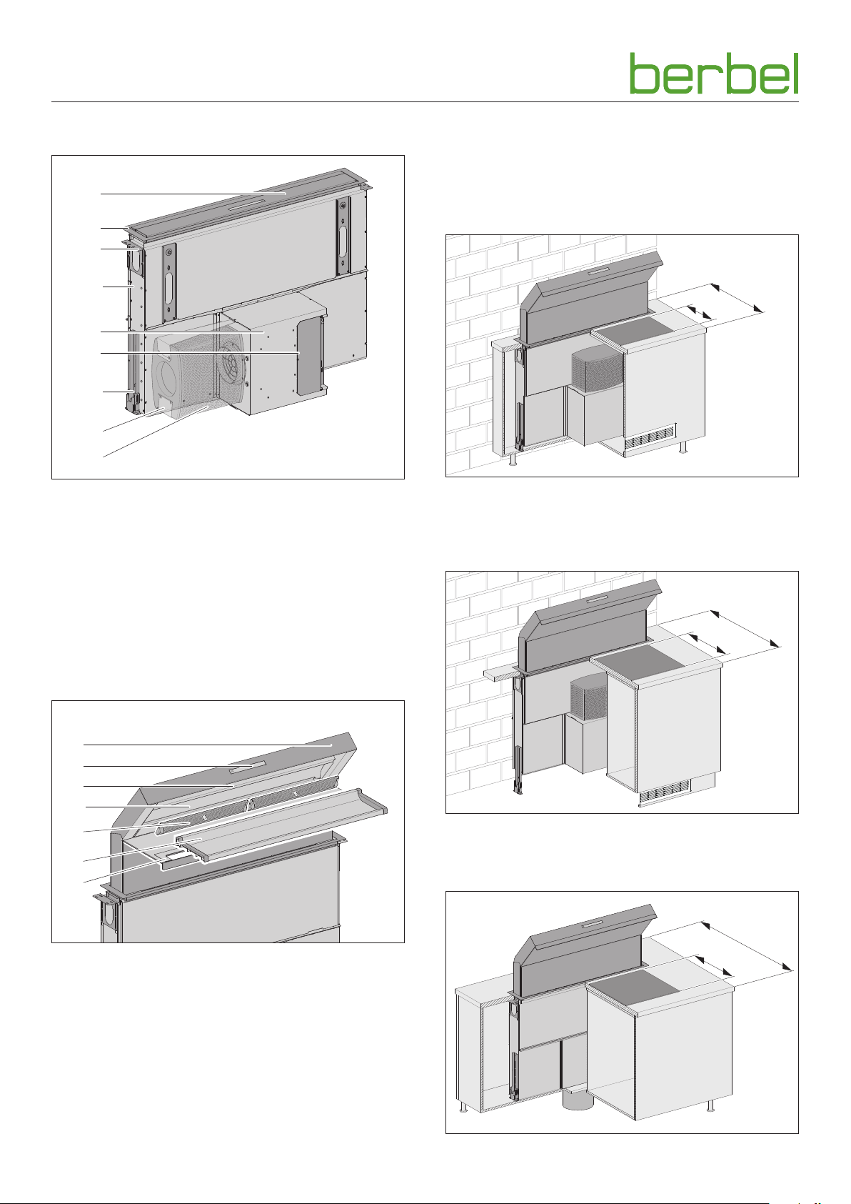
2.3 Product overview
A
B
C
D
E
F
G
H
I
A Table lift hood (retracted)
B Upper trim frame with water drip bowl
C Work top bracket
D Hood body
E Fan box
F Connectors
G Support foot (height-adjustable)
Optional:
H Retainer clip
I Recirculating or hybrid filter
2.4 Example installations
2.4.1 Example installation “in a cabinet (recirculated air mode)”
≥650
≥300
2.4.2 Example installation “cabinet rear (recirculated air mode)”
≥800
≥450
A
B
C
D
E
F
G
A Table lift hood (extended)
B Control panel
D “4.2 Control panel” (page 23).
C Lighting
D Upper section with bulging edge (removable)
E Capillar Trap
F Lower section
G Front trim
2.4.3 Example installation “island (extracted air mode)”
≥1050
≥450
6
6004067_a – 01.08.2018
Page 7
Product information
760 - 940
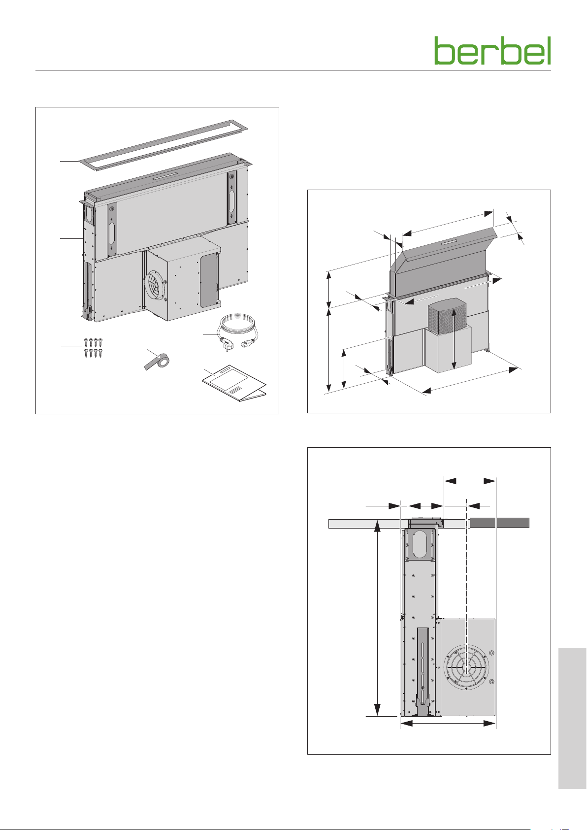
2.5 Scope of delivery
A
B
C
D
2.6 Installation dimensions
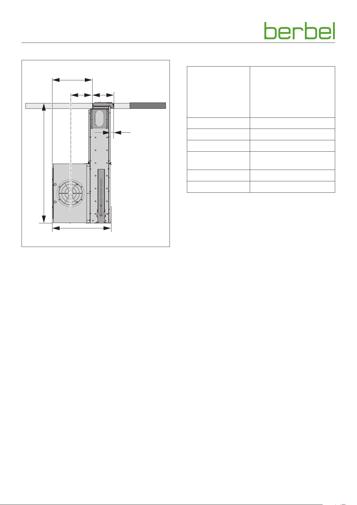
The fan box is pre-assembled in accordance with the order.
The precise installation dimensions are dependent on the
mounting position.
For the precise dimensions of the product, refer to the
order documents.
All variants
1000
110
162
88
1068
0 - 495
E
F
138
616
382
1106
A Upper trim frame with water drip bowl
B Hood body with extraction unit, fan box and connection
cable, 1.5 m
C Phillips head screws 3.5 x 20 mm
D Sealing strip
E Mains cable with plug and cold device plug
F Operating and installation instructions
The fastening material is only suitable for fastening to
wooden work tops. With different installation situations
(e.g. granite work tops) it is necessary to clarify the means of
fastening.
Further accessories may be required depending on the
operating mode.
D “9.2 Accessories” (page 34).
Observe the separate documentation for the hob.
Variants with fan box on the front - side view
203
13232 87
760 - 940
EN
6004067_a – 01.08.2018
365
7
Page 8
Product information
Variants with fan box on the rear - side view
250
134
132
760 - 940
16
2.7 Technical data
BTH100ML E01
Connection voltage 230 V / 50 Hz
Total power 211 W
Fan power consumption 170 W
Drive power
consumption
Lighting LED 10.4 W / 460 lx
Net weight approx. 70 kg
Information about energy consumption can be found in the
product fiche.
D “9.1 Product data sheet” (page 33).
30 W
365
Information on the model (e.g. serial number, year of
construction) is quoted on the front panel.
8
6004067_a – 01.08.2018
Page 9
Installation
3. Installation
3.1 Safety information for installation
D WARNING!
Hazard through disregard of the installation instructions!
This chapter contains important information for the safe
installation of the device.
☞ Read through this chapter carefully before installing the
device.
☞ Follow the safety instructions.
☞ Carry out the installation as described.
y Installation only by qualified specialist personnel.
D “1.2 Authorised target groups” (page 4).
y Electrical work only to be undertaken by qualified
electricians.
D “1.2 Authorised target groups” (page 4).
y The hob and other parts that can be touched must be
allowed to cool prior to installation.
y Store the film or other parts of the packaging in a location
which is inaccessible to children.
y The device must be in an undamaged and fault-free
condition prior to installation.
y Cables must not be kinked, crushed or damaged.
y Never open the fan housing.
y The power supply voltage must match the voltage
information quoted on the ratings plate.
D “2.7 Technical data” (page 8).
y Ensure that the power supply is stable and remains so
prior to the installation.
Connect the power supply only when instructed to do so
in the installation instructions.
Observe the safety information in the documentation for
the hob.
3.2 Requirements for the installation location
D WARNING!
Risk of death due to improper installation!
Disregard of the ambient conditions can lead to hazardous
situations, e.g. in the handling of electrical power or gas.
☞ Make sure that the requirements for the installation
location are complied with.
y Do not install in potentially explosive atmospheres.
y With heating points which use air from the room as their
oxygen supply (e.g. chimneys):
y A safety device is absolutely essential.
y The safety device (e.g. under-pressure monitor P4,
inspected in accordance with DIN 18841:2005-12 TÜV
and in accordance with DVGW-VP121) must prevent
gases being drawing to the room.
y An approval for commissioning (e.g. from a
chimneysweep) must be available.
y The installation is only permissible on level floors capable
of bearing the load, or in suitably strong cabinets.
y If it is necessary to break through the wall:
A wall break-through influences the structural integrity of
the building. There is a danger of collapse. This work must
only be carried out by a specialist.
y Make sure that the building electrical supply is properly
earthed.
y The power supply voltage present must match the
voltage information quoted on the ratings plate.
y A socket must be available in the vicinity of the
installation.
y The mains plug must be accessible after the installation
of the hood. Alternatively, all-pole isolating device (with a
contact gap of at least 3 mm) must be provided.
y The recirculating air filter or hybrid filter can be fitted
to the device in various positions. The recirculating air
filter or hybrid filter must be freely accessible at all times
in order to change the filter filling. The space must be
sufficiently large to allow the retainer clip to latch.
y During recirculating or hybrid operation sufficiently large
ventilation slots must be available for the ventilation.
y The air flowing out must be able to dissipate unimpeded.
Do not impede the air flow, e.g. through the installation of
objects on or above the device.
6004067_a – 01.08.2018
Country-specific, legal provisions must be observed.
EN
9
Page 10

Installation
3.3 Requirements for individual operating modes
Further accessories may be required depending on the
operating mode.
D “9.2 Accessories” (page 34).
3.3.1 Requirements for recirculated air mode
y Recirculated air filter at the fan outlet.
y Ventilation slots in the substructure.
Cross-section of the ventilation slots larger than 500 cm
y Filter filling freely accessible for changing.
3.3.2 Requirements for extracted air mode
y Exhaust air ducting at the fan outlet.
D “3.4 Requirements for the exhaust air ducting
(only for extracted air mode or hybrid mode)”
(page 10).
y Diameter of the exhaust air ducting at least 150 mm
(corresponds to a surface area of approx. 177 cm
2
).
y The exhaust air ducting is kept short where
possible (< 3 m) and optimised for the flow.
y Adequate fresh air supply is assured through the
installation of the necessary accessories.
y Window contact switch.
y Wall box.
3.3.3 Requirements for hybrid mode
y Hybrid filter at the fan outlet.
y Ventilation slots in the substructure.
Cross-section of the ventilation slots larger than 500 cm
y Connection of the exhaust air ducting to the hybrid filter.
D “3.4 Requirements for the exhaust air ducting
(only for extracted air mode or hybrid mode)”
(page 10).
y Diameter of the exhaust air ducting at least 150 mm
2
(corresponds to a surface area of approx. 177 cm
).
y Filter filling freely accessible for changing.
y Adequate fresh air supply is assured through the
installation of the necessary accessories.
y Window contact switch.
y Wall box.
3.4 Requirements for the exhaust air ducting
(onlyforextracted air mode or hybrid mode)
D WARNING!
Fire hazard and asphyxiation hazard due to improper
installation!
When using the exhaust air ducting with other devices
or when connecting an active exhaust air channel
(e.g. chimney), gases or smoke can be drawn into the room.
2
.
2
.
☞ Make sure that the requirements for the exhaust air
ducting are complied with.
y The exhaust air ducting is used exclusively by this device.
y The exhaust air ducting is made of non-combustible
material in accordance with DIN 4102 class 1.
y When using a chimney as the exhaust air duct:
y The chimney must not be used by other devices.
y The extracted air must be introduced into the
chimney using a 90° bend pointing upwards.
y Approval by a master chimney sweep.
y When routing the exhaust air ducting through the roof or
the outside wall:
y The cross-section must not be smaller than that of the
fan outlet.
y Installation of condensed water collector in the
exhaust air ducting in order to prevent water damage
inside the device. The condensed water collector must
be adequately dimensioned.
The cross-section, length, type and course of the exhaust
pipe affect the extraction efficiency. Changing the direction
of the air too severely leads to a loss of performance and to
noise.
To optimise the device performance:
y Keep the exhaust air ducting as short as possible and
route it directly to the outside.
y The stipulated cross-section of the exhaust air ducting is
complied with.
D “3.3 Requirements for individual operating modes”
(page 10).
y Exclusive use of ducts and bends with smooth inner
surfaces.
In order to avoid turbulence or backpressure in the
transported air - do not use:
y Spiral hoses.
y Flexible tubes.
y Flat deflection pieces.
y Sharp-edged exhaust air channels.
10
The exhaust air ducting must be in place before installing the
device.
6004067_a – 01.08.2018
Page 11

Installation
3.5 Installation procedure
Short overview:
1. Preparation for installation
2. Unpack the device
3. Check dimensions
4. Move fan box (optional)
5. Install filter (with recirculating or hybrid operation)
6. Install the device
7. Install the hob
8. Connect accessories
9. Connect exhaust air ducting (with exhausted air or hybrid
operation)
10. Establish electrical power supply
11. Check and carry out commissioning
3.5.1 Preparation for installation
The device is designed for installation in kitchen units.
The installation sequence may vary, depending on the local
conditions.
☞ Familiarise yourself with the installation situation and the
associated documents.
y Device and instructions.
y Accessories.
y Installation location.
y Intended operating mode.
y Order documents.
y Dimensions, position and alignment of the
components.
If accessories (e.g. wall box, window contact switch) are
required for the installation:
Observe the instructions for the accessories.
☞ Ensure that the accessories are correctly installed and
ready for connection.
☞ Ensure that the connection cables from accessories are
correctly routed and accessible.
The fastening material is only suitable for fastening to
wooden work tops. With different installation situations
(e.g. granite work tops) it is necessary to clarify the means of
fastening.
With installation of the device in a kitchen unit:
☞ Make sure that the kitchen units are equipped with
ventilation slots (e.g. with a ventilation grill).
D “9.2 Accessories” (page 34).
3.5.2 Unpack the device
D ATTENTION!
Hazard of glass breaking or other damage due to
incorrect handling!
The device and its surfaces can be damaged when being
unpacked or transported.
☞ Do not cut into the protective cardboard packaging.
☞ Keep objects that could scratch the device far away from
it (e.g. tools, belt buckles).
☞ Assemble the tools and materials required:
y Set-down area (e.g. trestle)
y Folding rule or measuring tape
y Pencil
y Spirit level
y Phillips head screwdriver, size 2
y Slotted screwdriver SL 2.5 x 0.4
y 2.5 mm Allen key
y 5.0 mm Allen key
y Ø 8 mm masonry bit
y Hammer drill
y Protective material (e.g. thick cardboard) for the hob
and the worktops
☞ Keep the installation area free of objects that could be in
the way or that could be damaged.
☞ Make sure that the hob and other parts that could be
touched have cooled down.
☞ Protect the hob and other surfaces in the installation area
(e.g. with thick cardboard).
☞ Ensure that the power supply is switched off and remains
so. Connect the power supply only when instructed to do
so in the installation instructions.
☞ Unpack the device and all accompanying parts carefully.
☞ Set the device down with the hob facing upwards on a
firm, clean and protective surface (e.g. thick cardboard).
☞ Check the device and its constituent parts for damage.
☞ Check the delivery is complete.
D “2.5 Scope of delivery” (page 7).
If parts are missing or damaged:
☞ Please consult your dealer or customer services.
☞ Remove the packaging material.
D “8.1 Dispose of packaging” (page 32).
EN
6004067_a – 01.08.2018
11
Page 12
Installation
3.5.3 Check dimensions
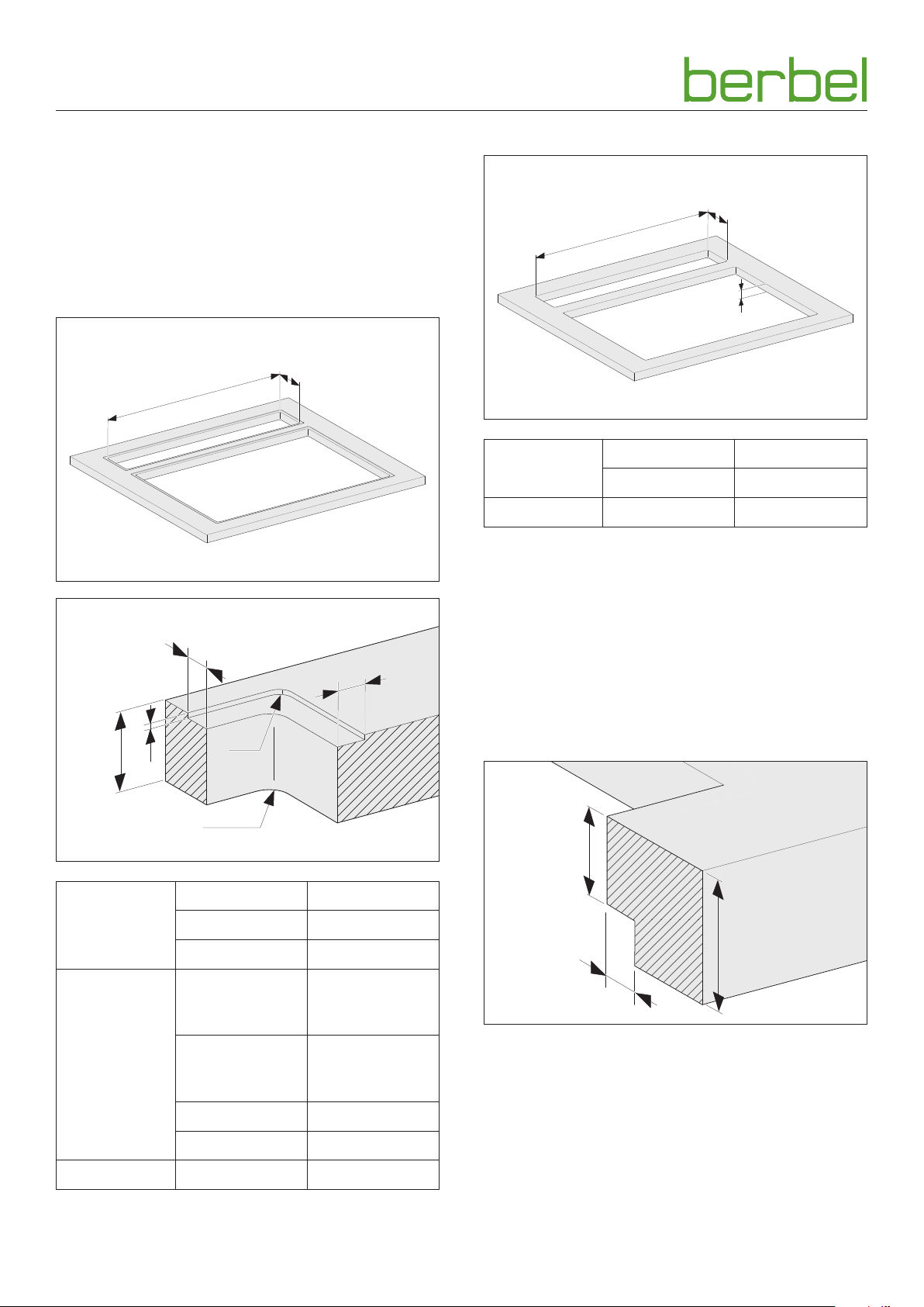
To determine the dimensions of the product, refer to the
order documents.
The device is mounted centrally behind the hob.
The recommended distance between the rear edge of the
hob and the front edge of the upper trim frame is 35 mm.
Flush installation
b
a
Counter-top installation
b
a
z
Width (a) 1042 mm
Cutaway
Depth (b) 132 mm
Work top Height (z) ≤ 40 mm
☞ Check the dimensions.
D “2.6 Installation dimensions” (page 7).
1
z
Cutaway
Milled recess
☞ Ensure that the work top is suitable for the hob
installation.
x2
x1
y
R5
Observe the hob instructions.
1
For work tops with a height from 40 to max. 100 mm,
a corresponding recess must be present on the underside.
Recess for work tops with a height from 40 to max. 100 mm:
≤ R7,5
40
Width (a) 1042 mm
Depth (b) 132 mm
Corner radius ≤ R7,5
41 - 100
30
Width
left, right (x1) /
Total width
Depth
front, back (x2) /
Total depth
14 mm /
1070 mm
16 mm /
164 mm
Height (y) 2 mm
Corner radius R5
Work top Height (z) ≤ 40 mm
12
1
6004067_a – 01.08.2018
Page 13
Installation
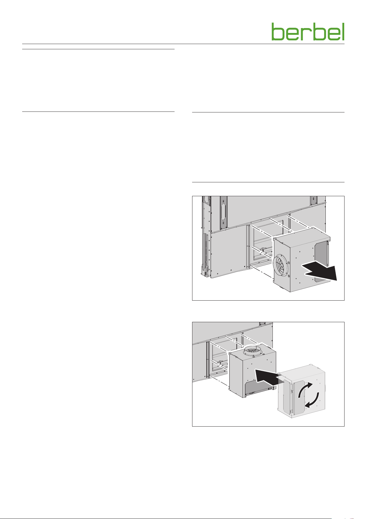
3.5.4 Move fan box (optional)
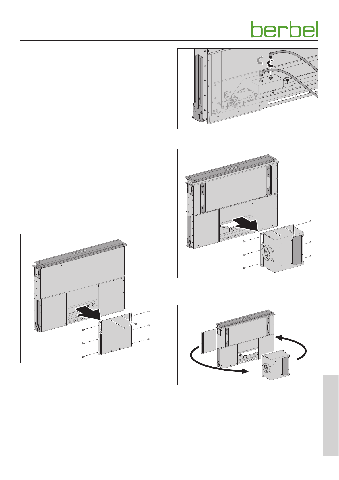
The fan box is pre-assembled in accordance with the order.
This assembly step is only necessary if the position of the fan
box must be retrospectively changed for installation in the
kitchen.
☞ Check whether the fan box is correctly positioned and
aligned.
Change the fan box position - front/rear
The position of the fan box can be changed if necessary.
To do this, unscrew the fan box and the middle trim panel
and replace.
D ATTENTION!
Danger of property damage through improper handling!
When disassembling the fan box it is possible to tear off
the pre-connected connection cables and damage the
connections.
☞ Loosen the connections carefully, without twisting the
plug.
☞ Carefully remove the fan box without straining the cables.
☞ After disassembly, refit the fan box such that the cables
are not kinked, crushed or damaged.
☞ Release the connections for the fan box in the hood body.
☞ Unscrew the screws on the middle trim panel on the side
without the fan box.
☞ Unscrew the screws on the fan box.
☞ Lift the fan box away from the hood body.
☞ Change the position of the trim panel and fan box.
EN
6004067_a – 01.08.2018
13
Page 14
Installation
D ATTENTION!
Danger of property damage due to incorrect connection!
The two connection cables are different - 8-pole and 12-pole.
With incorrect assignment and plugging in, the pins could
become bent and the connection cables rendered unusable.
☞ Ensure correct assignment of the connection cables -
8-pole and 12-pole.
☞ Connect the fan box in the hood body.
☞ Screw the fan box back in place.
☞ Screw the middle trim panel back on.
Change the fan box orientation - top/bottom/right/left
The orientation of the fan box can be changed in four
directions. To do so, unbolt the fan box and replace.
y When aligning the fan box upwards, to the right or left,
all operating modes are possible.
y When aligning the fan box downwards only extracted air
mode is possible.
D ATTENTION!
Danger of property damage through improper handling!
When disassembling the fan box it is possible to tear off
the pre-connected connection cables and damage the
connections.
☞ Carefully remove the fan box without straining the cables.
☞ Refit the fan box such that the cables are not kinked,
crushed or damaged.
☞ Unscrew the fan box.
☞ Align the fan box with the desired side facing upwards.
☞ Place the fan box on the trim panel. Pay attention to the
cables.
☞ Firmly bolt the fan box back in place.
14
6004067_a – 01.08.2018
Page 15
Installation
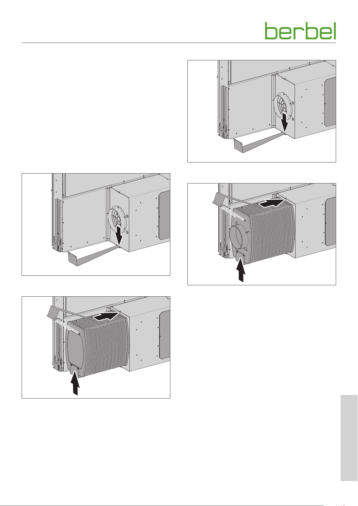
3.5.5 Install filter (with recirculating or hybrid operation)
The recirculating or hybrid filter can be installed in various
positions on the device, depending on the structural
situation. In these instructions for example, the position to
the side of the fan box is described.
Observe the order documents.
There is a pipe connection (Ø 150 mm) on the fan housing as
an installation aid for the installation of the filter.
The position of the filter is secured with a retainer clip.
The filter must be attached to the device before installation,
because the lower retainer clip is then easy to fasten.
Recirculated air mode
Hybrid mode
☞ Fasten the lower holding clamps to the fan housing.
☞ Fasten the lower holding clamps to the fan housing.
☞ Place the recirculated air filter onto the guide on the fan
housing.
☞ Slide the retainer clips over the nuts on the recirculated
air filter. The nuts must latch into the recesses.
☞ Ensure that the recirculated air filter is correctly installed.
☞ Place the hybrid filter onto the guide on the fan housing.
☞ Slide the retainer clips over the nuts on the hybrid filter.
The nuts must latch into the recesses.
☞ Ensure that the hybrid filter is correctly installed.
EN
6004067_a – 01.08.2018
15
Page 16
Installation
3.5.6 Install the device
D WARNING!
Danger of injuries through improper handling!
Installation of the device requires a great deal of physical
exertion due to its size and weight. If the device falls down,
serious injuries are possible.
☞ Install the device with two persons.
☞ Ensure stable footing during installation.
☞ Ensure that no other people are in the working area.
D ATTENTION!
Danger of property damage through improper handling!
Installation of the device requires a great deal of physical
exertion due to its size and weight. If the device falls, the
device, kitchen furnishings and other objects could be
damaged.
☞ Cover the working surface.
☞ Keep the installation area clear.
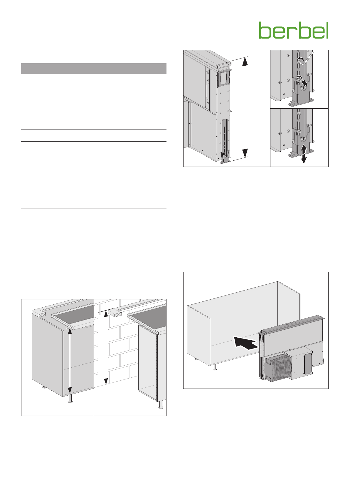
a - 25
Rough setting of the height:
☞ Release the two screws on the support foot.
☞ Adjust the support foot in the vicinity of the elongated
holes.
☞ Adjust the height per the determined dimension “a- 25”.
☞ Tighten the two screws again.
Observe the following specifications for the height of the
device:
y The height “a” from the upper edge of the top trim frame
to the lower edge of the support foot must lie between
760 and 940 mm.
y The upper edge of the panel must lie 25 mm below the
upper edge of the work top.
☞ Observe the installation dimensions.
D “2.6 Installation dimensions” (page 7).
a
a
The fine adjustment of the height takes place only once the
device is in the final position.
☞ Determine the assembly position.
☞ Ensure that the installation surfaces (floor or cabinet) are
level and load-bearing.
☞ Determine height “a”.
16
☞ Place the device in the desired position with two persons.
When doing so, observe the following specifications:
y With example installation “in a cabinet”: The device
must be slid into the cabinet without tipping it.
y For recirculating air and hybrid operation: For the filter
change, ensure sufficient space.
6004067_a – 01.08.2018
Page 17
Installation
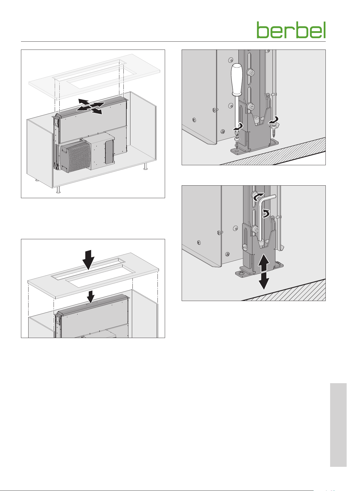
☞ Attach the support feet to the floor on both sides.
☞ Place the device in the final position.
☞ Align the device vertically.
☞ Make sure that the device and work top fit together.
☞ Ensure that the device is precisely in its final position.
☞ Set the work top in place.
Fine adjustment of the height:
☞ Adjust the height of the device so that it fits precisely
with the working area height. To do so, turn the middle
adjustment screw in the support feet on both sides.
6004067_a – 01.08.2018
EN
17
Page 18
Installation
2.
1.
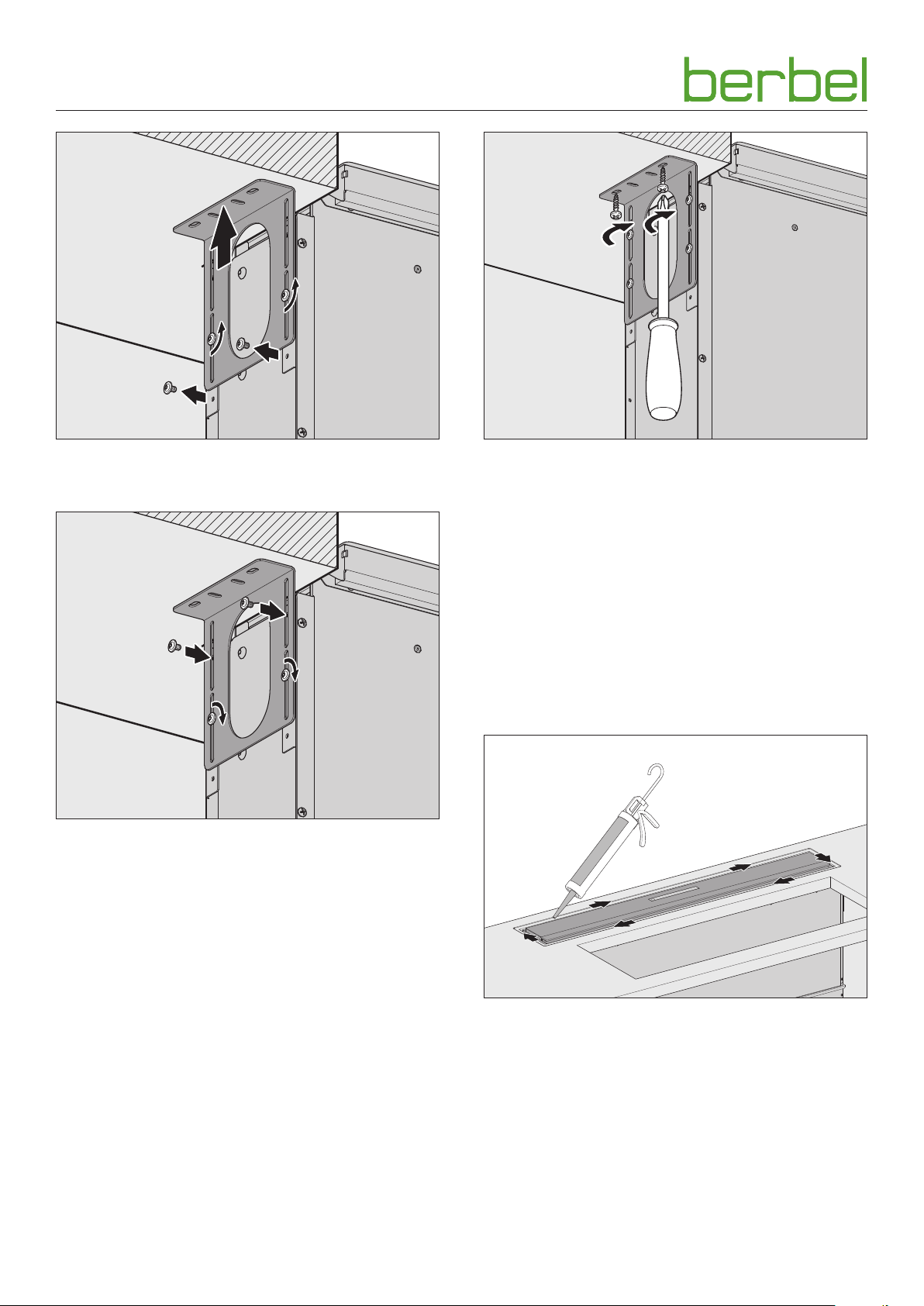
☞ Loosen the screws on the work top bracket.
☞ Slide the work top bracket into the correct position.
☞ Place both of the bottom screws into the top elongated
holes.
☞ Bolt all screws of the work top bracket to the device.
☞ Secure the work top bracket on both sides of the work
top.
y With wooden work tops:
The work top brackets must be bolted on.
y With different installation situations (e.g. granite work
tops):
It is necessary to clarify the means of fastening
(e.g. gluing).
It is necessary to drive the hood out slightly to install the
upper trim frame.
D “4. Operation” (page 22).
☞ Connect the device to the power supply.
18
☞ Bond the retainer for upper trim frame with silicone.
6004067_a – 01.08.2018
Page 19
Installation
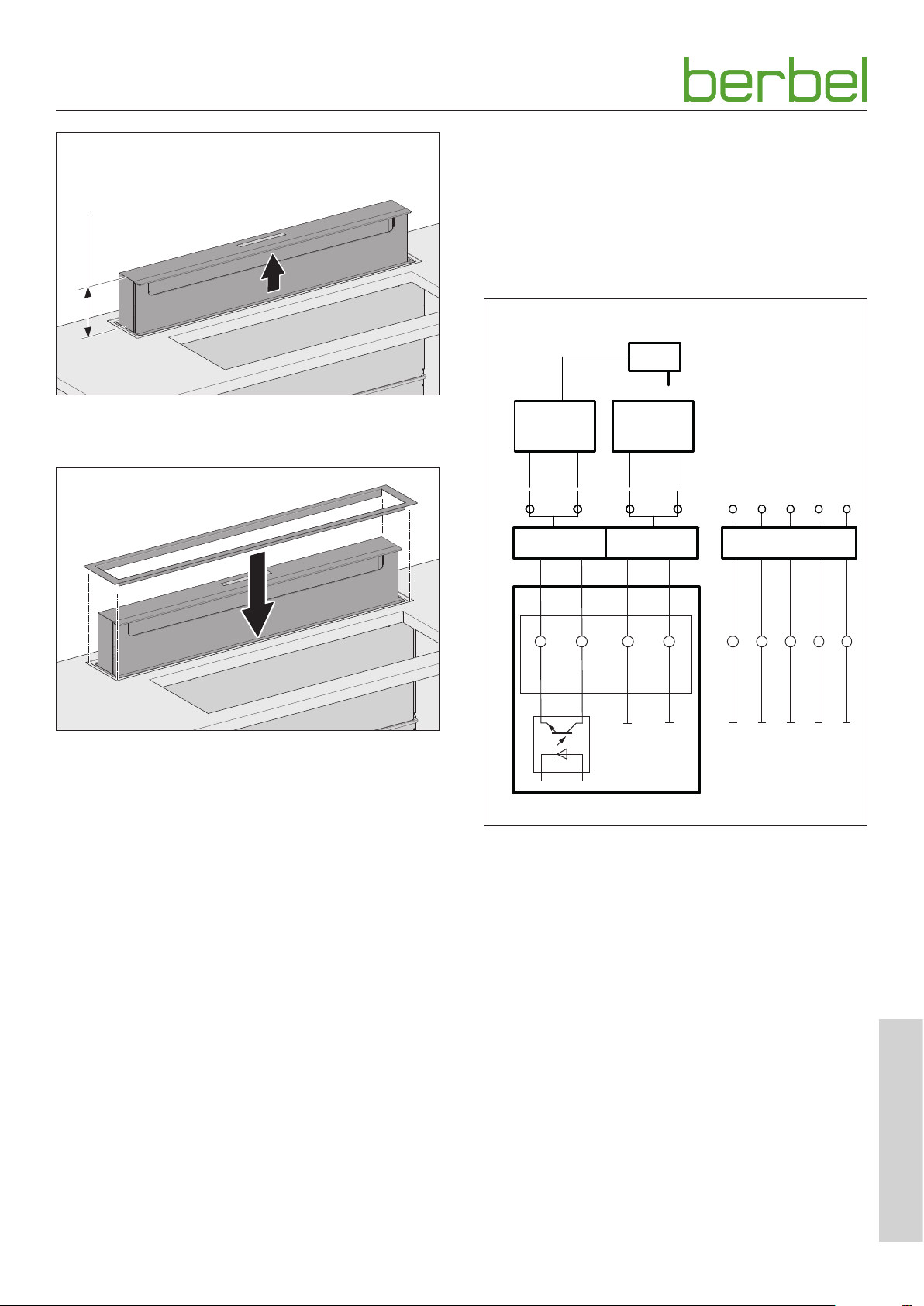
150 - 200
3.5.8 Connect accessories
Depending on the installation situation, accessories may be
connected to the hood:
y Wall box
y Window contact switch
y Under-pressure monitor
Observe the instructions for the accessories.
12 V DC
F
☞ Switch the device on.
☞ Drive the device approx. 150 to 200 mm upwards.
☞ Align the upper trim frame with the water drip bowl at
the front.
☞ Slide the upper trim frame over the device onto the
prepared work top.
☞ Make sure that the device can drive in or out without
touching the trim frame.
☞ Fully retract the device.
☞ Turn off the device.
☞ Disconnect the device from the power supply.
D “4. Operation” (page 22).
3.5.7 Install the hob
☞ Mount the hob.
Observe the hob instructions.
☞ Check the hob seal (e.g. with silicone).
MFK
GND
G
H
MFK
+ 5 V
4 5
C
X1
6
7
I
X1X1X1
8
E
12 V DC
D
2 31
BMK-F F-K
B
A
BMK1
–
–
A Control box
y BMK1: Wall sleeve contact, optocoupler collector,
max. 12 mA / 12 V DC, safe galvanic separated
y BMK2: Wall sleeve contact, optocoupler emitter,
max. 12 mA / 12 V DC, safe galvanic separated
B Terminal “BMK-F” for the wall box connection
C Terminal “F-K” (multifunction contact) for the window
contact switch or under-pressure monitor connection
D Control line from the wall box
E Wall box
F Wall box power unit
G Window contact switch
H Control line from the window contact switch
ST3
BMK2
+
+
9
X1
6004067_a – 01.08.2018
EN
19
Page 20
Installation
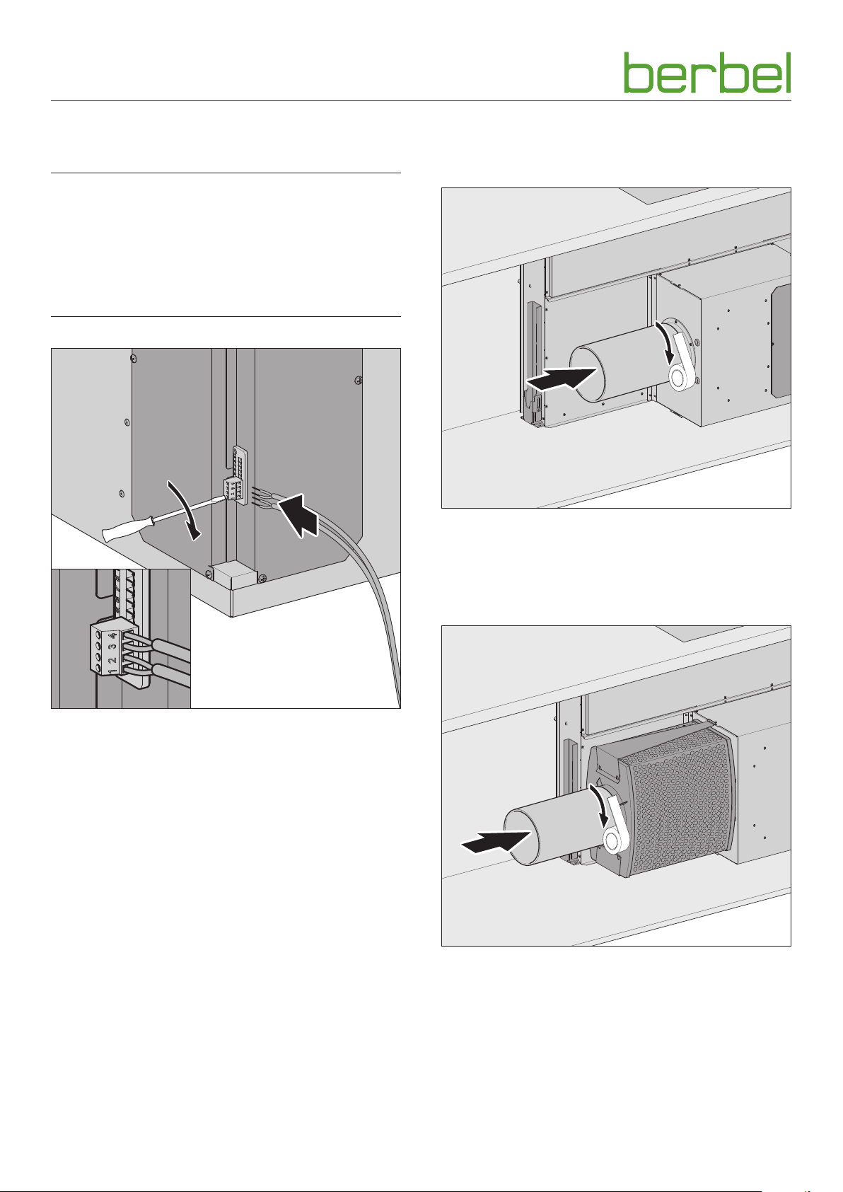
The connection is made through cable terminals on a
detachable plug on the fan box.
D ATTENTION!
Risk of damage through incorrect connection!
A mix-up of the control wires can result in damage to the
electronics.
☞ Be careful not to mix up connections when connecting
the control wires: Core 1 on terminal 1, core 2 on
terminal 2.
2.
1.
3.5.9 Connect exhaust air ducting (with exhausted air or hybrid operation)
Extracted air mode
1.
☞ Fit the exhaust outlet onto the guide on the fan housing.
☞ Seal the transition between the exhaust outlet and the
guide with the help of sealing tape.
☞ Ensure that the exhaust air duct is correctly fitted.
2.
Wall box
☞ Connect the wall box as follows:
y Core 1 on terminal 1
y Core 2 on terminal 2
y The wall box is closed when the control contacts are
open.
y The wall box is open when the control contacts are
closed.
Window contact switch
☞ Connect the window contact switch as follows:
y Blue/white core to terminal 3
y Brown/green core to terminal 4
y The hood‘s fan is only operational when the window is
open.
Under-pressure monitor
y The hood‘s fan is only operational when no critical under-
pressure is determined in the room.
Hybrid mode
1.
☞ Fit the exhaust outlet onto the collar of the hybrid filter.
☞ Ensure that the exhaust air duct is correctly fitted.
2.
20
6004067_a – 01.08.2018
Page 21

Installation
3.5.10 Establish electrical power supply
☞ Observe the voltage specifications on the ratings plate.
☞ Plug the cold device plug into the socket on the fan box.
☞ Plug the mains plug into the socket.
☞ Route the cable such that it is not kinked, crushed or
damaged and so that it will not get in the way when
replacing the filter filling.
☞ Make sure that the device can be disconnected on all
poles from the electricity supply after installation.
3.5.11 Check and carry out commissioning
D ATTENTION!
Risk of disruptions due to moisture in the device!
If the device is moved from a cold environment into a hot
one, condensation may form inside.
☞ Wait about 2-3 hours before bringing the device into
service.
☞ Check that the mains plug is freely accessible or that
an all-pole isolating device (min. 3 mm contact gap) is
present.
☞ Check that the mains cable and the electrical connection
cable are not kinked, crushed or damaged.
☞ Ensure that air outlets are not closed or covered.
With installation of the device in kitchen units:
☞ Ensure that the ventilation slots (e.g. ventilation grill) are
available and clear.
☞ Check the correct functioning of the device.
D “4. Operation” (page 22).
The device is ready for operation.
6004067_a – 01.08.2018
EN
21
Page 22

Operation
4. Operation
4.1 Safety information for operation
D WARNING!
Hazard through a disregard of the operating
instructions!
This chapter contains important information for the safe
operation of the device.
☞ Read through this chapter carefully before operating the
device.
☞ Follow the safety instructions.
y Operation only by authorised users.
D “1.2 Authorised target groups” (page 4).
y No operation permitted by children under 8 years old and
persons who would not be able to properly assess the
hazards associated with handling the device.
y Do not use during a fire or when there is an imminent
danger of fire (e.g. a smell of gas).
y No use of gas hobs.
y Do not flambé near the device. Fire hazard.
y No unattended deep frying near the device.
y When in use, the hob and other parts that could be
touched can become very hot. There is a risk of burning.
y Grease residues should be removed. Grease residues pose
a fire hazard.
y No moisture in the device.
y Avoid dripping or splashing water. Particularly the
penetration of liquid (e.g. due to slopping over during
cooking) in the joints, when the device is driven out.
y Containers with liquids (e.g. vases, bottles) must not
be placed on the device.
y Do not impede the air flow.
y Do not impede the air channel on the underside of the
device.
y Only use if the lower section and Capillar Trap are
installed.
y In recirculated air mode:
Do not cover the air outlets (e.g. glasses/plates on or in
front of the ventilation slots). Out-flowing air must be
able to escape through the ventilation slots without
impediment. Otherwise backpressure may form. If the
cooking vapours are no longer able to escape there is a
danger of fire.
y With exhausted air or hybrid operation:
Adequate fresh air supply must be assured.
Measures to ensure a sufficient supply of fresh air:
☞ Open the windows.
☞ Open the doors.
☞ Ensure that the window contact switch and the wall box
are installed and ready for operation.
☞ With heating points which use air from the room as their
oxygen supply (e.g. chimneys):
Make sure that the mandated safety devices are
functioning correctly.
22
6004067_a – 01.08.2018
Page 23
Operation
4.2 Control panel
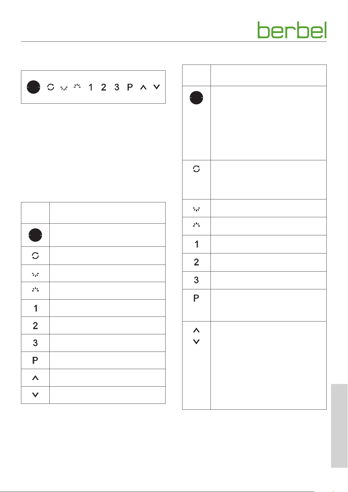
The device is controlled via the control panel.
The position of the control panel can be seen in the trough
of the ON/OFF button at any time. The remaining touch fields
illuminate if the device is switched on.
After switching on the mains power supply, the device needs
a few seconds in order to adapt itself to the environmental
conditions. During this time, it cannot be operated.
Touching a touch field executes the corresponding function:
y Touch field illuminates dimly = Function not active
y Touch field illuminates brightly = Function active
Touch
field
Function
ON / OFF, access configuration mode
Recirculated air mode, check filter filling
indicator
Hob lighting
Effect lighting - no function
Power level 1
Power level 2
Power level 3
4.3 Normal operation
Touch
field
Function
The device is turned off.
☞ Touch the touch field 1x.
The device switches on.
The device is switched on.
☞ Touch the touch field 1x.
The device switches off.
If the run-on function is activated:
The run-on time (10 minutes) starts
automatically in the last selected power level.
Touch field illuminates brightly:
Recirculated air mode is switched on.
Touch field flashes:
The filter filling must be replaced.
Touch field illuminates brightly:
Hob lighting is switched on.
Touch field illuminates brightly:
Effect lighting (optional) is switched on.
Touch field illuminates brightly:
Power level 1 (lowest fan power) is active.
Touch field illuminates brightly:
Power level 2 (medium fan power) is active.
Touch field illuminates brightly:
Power level 3 (high fan power) is active.
Touch field illuminates brightly:
POWER power level (max. fan performance)
is active for max. 6 minutes. Then the device
switches to power level 3.
The touch fields are only active if the device is
switched on.
☞ Touch the touch field 1x.
The device moves in the desired direction.
Power level POWER (max. 6 minutes)
Lift function “Extend”
Lift function “Retract”
6004067_a – 01.08.2018
If the touch field is actuated during
movement, the device stops in the current
position.
The device moves to the appropriate end
position without further actuation.
As soon as the device is fully retracted, all
active functions are switched off.
EN
23
Page 24
Operation
To achieve an optimal efficiency in removing cooking fumes:
☞ Turn the device on 1-2 minutes before you start cooking.
This allows the flow of air to build up, and the fumes are
removed at an early stage.
☞ In order to collect the cooking fumes effectively, use the
rear hob plates for intensive cooking.
☞ Avoid cross-currents (e.g. draughts) across the hob.
☞ During the cooking process, switch to a power level that
is appropriate for the intensity of the cooking vapours:
y Power level 1 - lowest fan power
y Power level 2 - medium fan power
y Power level 3 - high fan power
☞ If the intensity of the cooking vapours does not subside,
switch to a higher power level.
☞ Switch to the POWER setting if frying.
☞ Turn on the run-on function when you have finished
cooking.
D “4.3.1 Run-on function” (page 24).
☞ Check the fresh air supply at regular intervals.
☞ Use the device also to reduce other unpleasant smells.
Such as from:
y Onions and garlic
y Oven, microwave and steamer
y Fondue and raclette
D WARNING
4.3.1 Run-on function
The device comes with a run-on function. If this function is
used, the device will work for a further ten minutes at the last
chosen power level.
In recirculated air mode, it is necessary to use the run-on
function so that the device can remove the remaining
odours. Using the run-on function increases the life of the
filter filling. The filter filling must be replaced at regular
intervals.
The run-on function can be switched on manually or
automatically. The automatic run-on function is activated in
configuration mode.
D “4.4 Configuration” (page 25).
Touch
field
Function
The device is switched on.
If the automatic run-on function is activated:
☞ Touch the touch field 1x.
The device switches off.
The run-on time starts automatically in the last
selected power level.
Fire hazard due to grease residue!
In operation grease residue, which is highly inflammable,
collects in and on the device.
☞ Clean the device properly.
D “5. Cleaning” (page 26).
If you switch the machine on and hear an unusually loud fan
noise:
☞ Clean the device.
☞ Observe the stipulations for cleaning.
D “5. Cleaning” (page 26).
If you switch the machine on and notice a smell:
☞ Change the filter filling.
☞ Observe the stipulations for changing the filter filling.
D “6.2.2 Replacing filter filing (with recirculating and
hybrid mode)” (page 28).
After 6 hours without operation, the device (including
lighting) automatically switches off.
If the automatic run-on function is not
activated:
☞ Touch the touch field 2x - within
2 seconds.
The device switches off.
The run-on time is started manually in the last
selected power level.
During the run-on time (10 minutes), the
operating symbol for the selected power level
will flash.
4.3.2 Extraction mode / recirculated air mode changeover
If the device is configured for hybrid mode, it is possible to
switch between extraction mode and recirculated air mode
at any time after activating the changeover function.
The changeover function is activated in configuration mode.
D “4.4 Configuration” (page 25).
24
6004067_a – 01.08.2018
Page 25
Operation
Touch
field
4.3.3 Check filter filling indicator
The device has a check indicator in order to remind the
operator to change the filter filling. In recirculated air mode,
the check indicator flashes every 350 hours of operation.
The hours counter is started anew by switching off the check
indicator.
The check indicator is switched off in configuration mode.
D “4.4 Configuration” (page 25).
Touch
field
Function
If the changeover function is activated:
☞ Touch the touch field 1x.
Touch field illuminates dimly:
The device operates in exhausted air mode.
The wall box is opened.
The cleaned air is discharged outside.
Touch field illuminates brightly:
The device is operating in recirculated air mode.
The wall box is closed.
The cleaned air is discharged into the room.
Function
Touch field flashes:
The filter filling must be replaced.
D “6.2.2 Replacing filter filing (with recirculating
and hybrid mode)” (page 28).
In the configuration mode, the following functions can be
activated or deactivated by touching the corresponding
touch fields.
Touch
field
Function
Effect lighting - no function.
As delivered, the touch field is turned off.
The touch field can be activated in
configuration mode.
☞ Touch the touch field 1x.
Touch field illuminates brightly:
The touch field does not have any function on
this device.
Extraction mode / recirculated air mode
changeover.
As delivered, the function is turned off.
☞ Touch the touch field 1x.
Touch field illuminates brightly,
touch field for recirculated air mode
illuminates dimly:
The changeover function is activated.
☞ Touch the touch field 1x.
Touch field illuminates dimly,
touch field for recirculated air mode is off:
The changeover function is deactivated.
Check filter filling indicator.
The function is set such that touch field
for recirculated air mode flashes every
350 operating hours.
4.4 Configuration
Touch
field
6004067_a – 01.08.2018
Function
The device is switched on, the power stages
are not active.
☞ Touch the touch field 1x - for longer than
10 seconds.
The power level touch field flashes 5x.
The device switches to configuration mode.
The configuration mode is turned on.
To exit the configuration mode:
☞ Touch the touch field 1x.
The settings are now saved.
All operating symbols illuminate for 5 seconds.
The device is in normal mode again.
The filter filling has been changed:
☞ Touch the touch field 1x.
Touch field illuminates brightly:
The hour counter starts anew, the touch field
for recirculated air mode is switched off.
Automatic run-on.
As delivered, the function is turned off.
☞ Touch the touch field 1x.
Touch field illuminates brightly:
Automatic run-on is activated.
EN
25
Page 26
Cleaning
5. Cleaning
5.1 Safety information for cleaning
D WARNING!
Hazard through a disregard of the cleaning instructions!
This chapter contains important information for the safe
cleaning of the device.
☞ Read through this chapter carefully before cleaning the
device.
☞ Follow the safety instructions.
D ATTENTION!
Danger of damage due to falling parts!
The bulging edge, the lower section and the Capillar Traps
can fall down when being removed and damage the
cooktop, the kitchen units or other objects.
☞ Hold the parts tightly when removing.
y Cleaning only by authorised users.
D “1.2 Authorised target groups” (page 4).
y No cleaning permitted by children under 8 years old and
persons who would not be able to properly assess the
hazards associated with handling the device.
y After use, the hob and other parts that could be touched
may still be hot. There is a risk of burning.
y Grease residues should be removed. Grease residues pose
a fire hazard.
5.2 Cleaning procedures
The device draws in dirt particles (e.g. grease and oil particles)
with the air from the room. The dirt particles are separated
and collected in the upper section, on the bulging edge, in
the lower section and in the Capillar Trap.
Before every cleaning:
☞ Turn off the device.
☞ Make sure that the hob and other parts that could be
touched have cooled down.
D ATTENTION!
Danger of damage through improper cleaning!
Sharp-edged objects, abrasive or unsuitable cleaning agents
can damage the device.
The following cleaning agents are unsuitable and must not
be used:
y Acetone
y Trichloroethylene
y Solutions on a cellulose basis (e.g. cellulose thinner)
y Artificial resin thinner
y Abrasive media
y Polishes containing silicone
y Polishes containing oil
y Wax
y Water vapour
y On painted surfaces: Microfibre cloth
☞ Keep objects that could scratch the device away from it
(e.g. rings).
☞ Use mild household cleaner (e.g. alkali-free, pH-neutral
multipurpose cleaner).
☞ Use a soft, damp cloth.
☞ Clean without exercising excessive pressure.
The device should be cleaned regularly:
y Control panel, surface, upper section, bulging edge and
lower section after each cooking process.
y The Capillar Traps no later than three weeks if used daily.
y The water drip bowl as necessary or with the penetration
of liquid (e.g. due to slopping over during cooking) in the
joints.
The instructions and information on the cleaning agent
should be observed.
Control panel
☞ Clean the control panel with a lint-free, slightly damp
cloth (e.g. a microfibre cloth).
☞ Dry the control panel with a lint-free, soft cloth.
Surfaces
☞ Clean the surfaces with a soft, damp cloth and a mild
household cleaner.
☞ Dry the surfaces with a soft cloth.
26
6004067_a – 01.08.2018
Page 27
Cleaning
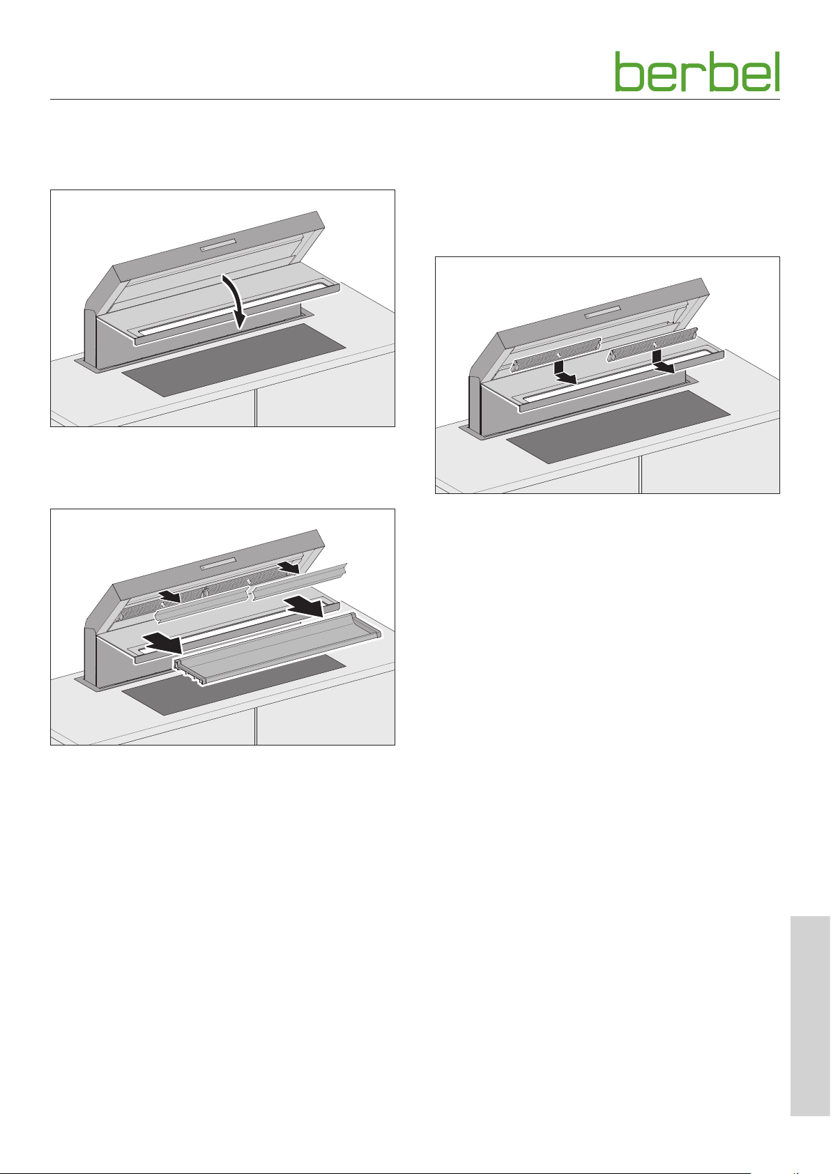
Upper section, bulging edge and lower section
The front trim is magnetically held in the device. The upper
section, the bulging edge and the lower section lie in the
front trim.
☞ Drive the device at least halfway out. The front trim must
be driven out fully.
☞ Fold the front panel down.
Capillar Trap
The two Capillar Traps are inserted and held magnetically in
place in the device.
In order to remove the Capillar Traps:
y The device must be driven at least halfway out.
y The front trim must be opened.
☞ Pull the Capillar Trap downwards by the handle, out of the
magnetic fasteners.
☞ Draw the Capillar Trap forwards and out of the device.
☞ Clean the Capillar Trap e.g. in a dishwasher.
☞ Clean the upper section with a soft, moist cloth.
☞ Make sure that the Capillar Trap is completely dry.
☞ Prior to insertion, align Capillar Trap such the label “Down”
points downwards.
☞ Insert the Capillar Trap such that it is held in the device by
the magnetic fasteners.
☞ Pull the lower section out forwards with both hands.
☞ Pull the bulging edge from the upper section.
☞ Clean the upper section with a soft, moist cloth.
☞ Clean the bulging edge and the lower section with a soft,
moist cloth or in a dishwasher.
☞ Dry the upper section, the bulging edge and the lower
section with a soft cloth.
☞ Take hold of the lower section with both hands, the drip
bowl points upwards.
☞ Insert the lower section into the device until it reaches
the rear stop.
☞ Place the bulging edge onto the upper section.
☞ Check whether the bulging edge is correctly placed and
held by the magnets.
☞ Close the front panel until the two magnetic fasteners can
be heard to click into place.
After cleaning, the interior parts should be reinserted.
EN
6004067_a – 01.08.2018
27
Page 28
Maintenance
6. Maintenance
6.1 Safety information for maintenance
D WARNING!
Hazard through a disregard of the maintenance
instructions!
This chapter contains important information for the safe
maintenance of the device.
☞ Read through this chapter carefully before carrying out
maintenance work on the device.
☞ Follow the safety instructions.
☞ Carry out the maintenance work as described.
y Repairs only by qualified specialist personnel.
D “1.2 Authorised target groups” (page 4).
y Electrical work only to be undertaken by qualified
electricians.
D “1.2 Authorised target groups” (page 4).
y Maintenance only by authorised users.
D “1.2 Authorised target groups” (page 4).
y No maintenance work permitted by children under
8 years old and persons who would not be able to
properly assess the hazards associated with handling the
device.
6.2 Maintenance
6.2.1 Changing the lamps
The device is fitted with maintenance-free LED lighting. In
the event of a fault:
☞ Please consult your dealer or customer services.
6.2.2 Replacing filter filing (with recirculating and hybrid mode)
Odours are trapped in the filter filling in the recirculated air
filter. The odour-free, cleaned room air is fed back into the
room.
Recirculating air filters and hybrid filters are maintenancefree for up to two years. Then filter filling must be replaced at
regular intervals.
Top-up pack:
D “9.2 Accessories” (page 34).
Maintenance intervals
y Daily use: With odours in the exhaust air or after
24 months at the latest.
y Occasional use: With odours in the exhaust air or after
36 months at the latest.
D ATTENTION!
y After use, the hob and other parts that could be touched
may still be hot. There is a risk of burning.
y Never open the fan housing.
y The recirculating air filter and hybrid filter must be freely
accessible.
Danger of property damage through falling parts!
When working on the device, parts of the device or tools
could fall and damage the kitchen equipment.
☞ Protect the cooled hob and other surfaces in the cooking
area (e.g. with thick cardboard).
28
6004067_a – 01.08.2018
Page 29
Maintenance
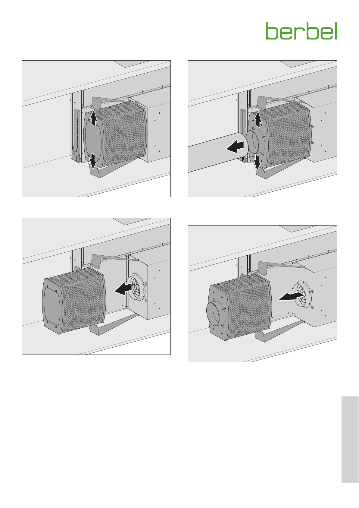
Remove the recirculation air filters
☞ Release the retainer clip from the recirculated air filter.
Removing the hybrid filter
1.
2.
☞ Remove the exhaust pipe from the hybrid filter.
☞ Release the retainer clip from the hybrid filter.
☞ Remove the filter.
The replacement of the filter filling is carried out as
described in the associated instructions.
☞ Change the filter filling.
☞ Clean the filter from the outside (e.g. through extraction
with a vacuum cleaner).
☞ Attach the filter again.
D “3.5.5 Install filter (with recirculating or hybrid
operation)” (page 15).
☞ Switch off the check indicator on the control panel.
D “4.4 Configuration” (page 25).
6004067_a – 01.08.2018
☞ Remove the filter.
The replacement of the filter filling is carried out as
described in the associated instructions.
☞ Change the filter filling.
☞ Clean the filter from the outside (e.g. through extraction
with a vacuum cleaner).
☞ Attach the filter again.
D “3.5.5 Install filter (with recirculating or hybrid
operation)” (page 15).
☞ Switch off the check indicator on the control panel.
D “4.4 Configuration” (page 25).
EN
29
Page 30

Maintenance
6.3 Fault rectification
Possible faults are described below:
Description of the fault.
y Possible cause.
☞ Remedy.
The fan does not work.
y No power supply.
☞ Check that the all-pole mains switch is connected.
☞ Switch the mains switch on.
y The breaker may have been tripped or is defective.
☞ Check to see if the breaker has tripped.
☞ If you use electric circuit breakers, turn the circuit
breaker on again.
☞ For other types of fuse, consult a qualified electrician.
y The device is not switched on.
☞ Check all power levels.
D “4.3 Normal operation” (page 23).
y The device is connected to a window contact switch and
the window is closed.
☞ Open the window.
y The device is connected to an under-pressure monitor.
The under-pressure monitor detects a critical underpressure.
☞ Open a window.
☞ Wait until the air pressure returns to normal.
The lighting does not work.
y No power supply.
☞ Check that the all-pole mains switch is connected.
☞ Switch the mains switch on.
y The breaker may have been tripped or is defective.
☞ Check to see if the breaker has tripped.
☞ If you use electric circuit breakers, turn the circuit
breaker on again.
☞ For other types of fuse, consult a qualified electrician.
y The lamp has blown.
☞ Please consult your dealer or customer services.
Smells occur during operation.
y The filter filling is used up.
☞ Change the filter filling.
D “6.2.2 Replacing filter filing (with recirculating and
hybrid mode)” (page 28).
Poor device performance.
y The recirculated air filter is clogged.
☞ Replace the filter filling of the recirculated air filter.
D “6.2.2 Replacing filter filing (with recirculating and
hybrid mode)” (page 28).
y The hybrid filter is clogged.
☞ Replace the filter filling of the hybrid filter.
D “6.2.2 Replacing filter filing (with recirculating and
hybrid mode)” (page 28).
y The exhaust pipe was not properly connected or installed.
☞ Please consult your dealer or customer services.
y In the case of devices with recirculated air mode, there is
a lack of sufficient ventilation in the substructure.
☞ Ensure that the ventilation slots (e.g. ventilation grill)
are available, clear and sufficiently large (cross-section
2
larger than 500 cm
).
Control panel does not react after being touched several times.
y The control panel is soiled.
☞ Clean the control panel.
D “5. Cleaning” (page 26).
y The device software requires a restart.
☞ Briefly disconnect the mains power supply.
Moisture in the device.
y Dripping or splashing water has penetrated the device.
y Liquid (e.g. from vases, bottles on the device) has
penetrated the device.
☞ Immediately shut off the power supply, by removing
the fuse.
☞ Make sure that the power supply cannot be
unintentionally reconnected. For example by tasking
a person with ensuring that the fuse/breaker is not
restored/switched on.
☞ Ensure that no more liquid can penetrate the device.
☞ Allow the device to dry.
☞ Have the device checked and repaired by qualified,
specialist personnel prior to using the device again.
If a fault persists:
☞ Please consult your dealer or customer services.
30
6004067_a – 01.08.2018
Page 31
Dismounting
7. Dismounting
D WARNING!
Danger of injuries through improper handling!
Disassembly of the device requires a great deal of physical
exertion due to its size and weight. If the device falls down,
serious injuries are possible.
☞ Disassemble the device with two persons.
☞ Ensure stable footing during disassembly.
☞ Ensure that no other people are in the working area.
D ATTENTION!
Danger of property damage through improper handling!
Disassembly of the device requires a great deal of physical
exertion due to its size and weight. If the device falls, the
device, kitchen furnishings and other objects could be
damaged.
☞ Disassemble the device with two persons.
☞ Cover the cooled hob.
☞ Keep the installation area clear.
☞ Ensure that the device is fully retracted.
☞ Disconnect all poles of the power supply for the device.
☞ Pull out the mains plug.
If present:
☞ Remove any accessory connection cables.
For exhausted air and hybrid operation:
☞ Remove the sealing strip.
☞ Remove the exhaust air duct.
For recirculating air and hybrid operation:
☞ Remove the filter.
☞ Remove the connecting cable on the device.
☞ Release the upper trim frame from the work top.
☞ Lift the upper trim frame up and away from the work top.
☞ Release the threaded connection of the work top bracket
on the work top.
☞ Release the threaded connection of the support foot on
the floor.
☞ Have two persons lift the hood body.
☞ Set the parts of the device down on a firm and protective
surface.
6004067_a – 01.08.2018
EN
31
Page 32
Disposal
8. Disposal
8.1 Dispose of packaging
D ATTENTION!
Risk of environmental damage due to improper disposal
of the packaging!
☞ Do not put the packaging into the normal household
waste.
☞ Take the packaging for environmentally friendly and
proper recycling.
The packaging provides protection from transport damage.
Only the original packaging guarantees sufficient protection
during transportation.
☞ Store the packaging in a location which is inaccessible to
children.
The packaging materials have been selected from an
environmentally friendly perspective and are made from
re-usable materials. The packaging materials can be returned
to the raw materials cycle after use. This saves valuable raw
materials.
y The outer packaging is made from cardboard.
y The filling material and the insets are made from
cardboard or styrofoam.
y The protective film and bags are made from
polythene (PE).
☞ Dispose of the packaging in an environmentally friendly
manner, separated by materials.
8.2 Dispose of the device
D ATTENTION!
Risk of environmental damage due to improper disposal
of the device!
The device is subject to the European Directive 2012/19/EU
and should not be disposed of with household waste.
☞ Do not put the device into the normal household waste
at the end of its service life.
☞ Enquire about the disposal options or environmentally
friendly and proper recycling opportunities with your
municipal or regional authorities.
☞ Render the device unusable after dismounting it, e.g. by
cutting the de-energised mains cable.
☞ Dispose of the device in accordance with the legal
provisions via a professional disposal centre or your local
disposal facility.
32
6004067_a – 01.08.2018
Page 33
Annex
9. Annex
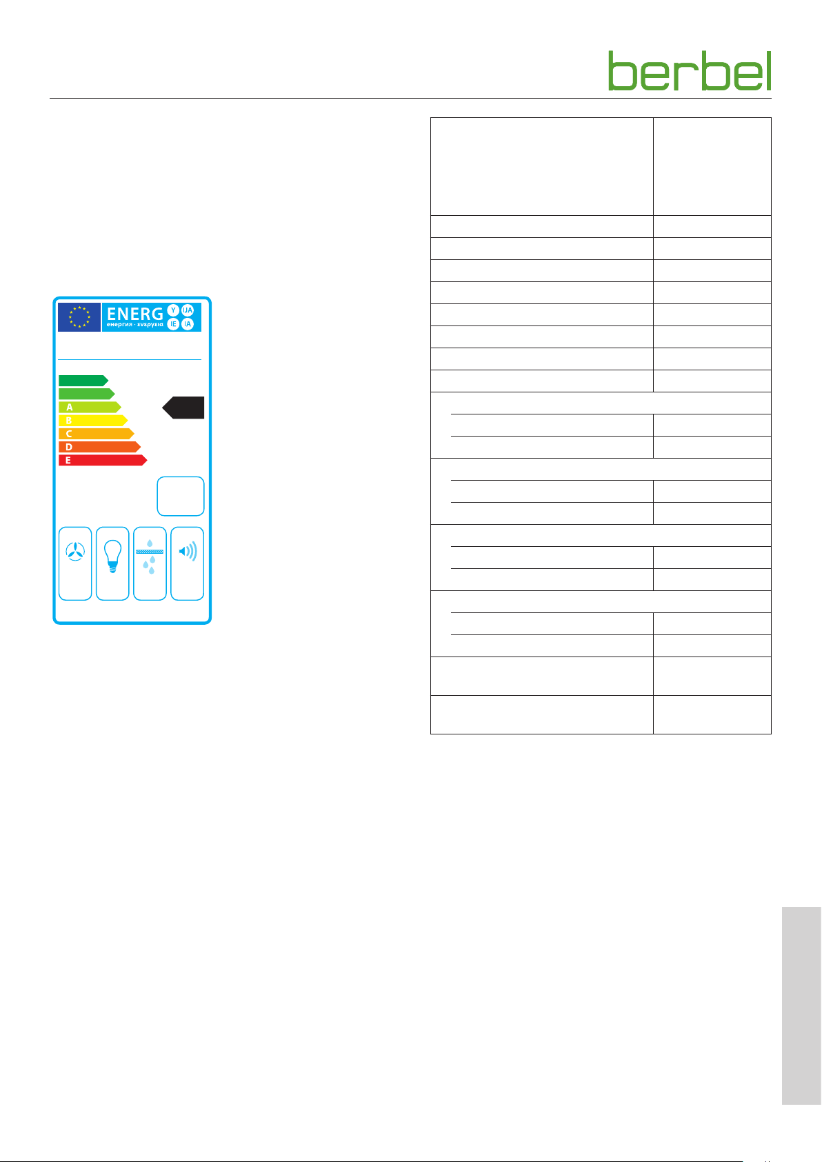
9.1 Product data sheet
In accordance with article 3 section 1 b point ii of the
Regulation (EU) No. 65/2014
BTH100ML E01
berbel
++
A
+
A
BTH 100 ML E01
A
44
kWh/annum
ABCDEFG ABCDEFG
65/2014
ABCDEFG 63
dB
BTH100MLE01
Annual energy consumption in kWh 44,2
EEI Hood Class A
FDE Hood 32,0
FDE Hood Class A
LE Hood 44,2
LE Hood Class A
GFE Hood 76,9
GFE Hood Class C
Flow rate in extracted air mode in m³/h
Stage min./max. 320/520
Stage Power/Intense 640
Flow rate in recirculated air mode in m³/h
Stage min./max. 240/410
Stage Power/Intense 500
Noise power level in extracted air mode in db(A)
Stage min./max. 49/63
Stage Power/Intense 67
Noise power level in recirculated air mode in db(A)
Stage min./max. 49/63
Stage Power/Intense 67
Power consumption stand-by
in Watt (W)
Power consumption stand-off
in Watt (W)
0,8
0,5
6004067_a – 01.08.2018
EN
33
Page 34
Annex
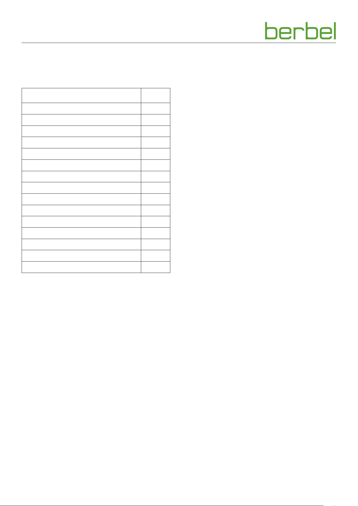
9.2 Accessories
When using accessories, the associated documentation
must be observed.
Article no.
Recirculated air filter BUF 150 + 1003325
Hybrid filter BHF 150 + 1003607
Holding clamp (single) 2000658
Top-up pack berbel Pro Aktiv 150 1000875
Wall box BMK-F 150 1001330
Wall box BMK-Z 150 1001390
Radio window contact switch 1002916
Ventilation grill stainless steel, 2-part 6002271
Conversion to remote control BFB 1004767
Exhaust air set I round 150 1004729
Exhaust air set II flat 150 1004730
Exhaust air set III flat 150 double 1004731
Exhaust air set ECO I round 150 1004732
Exhaust air set ECO II flat 150 1004733
9.3 Contact
If you have any questions or suggestions, please select from
the following options:
Post: berbel Ablufttechnik GmbH
Sandkampstraße 100
D-48432 Rheine
Tel: +49 (0) 5971 80 80 9 - 0
Mon to Thu 08:00 – 17:30 hrs
and Fri 08:00 – 16:30 hrs
Fax: +49 (0) 5971 80 80 9 - 10
Internet: www.berbel.de
email: [email protected]
Contact the manufacturer‘s customer support
department
There are several ways for you to contact our customer
service. Please select from the following options:
Tel: +49 (0) 5971 80 80 9 - 660
Mon to Thu 08:00 – 17:30 hrs
and Fri 08:00 – 16:30 hrs
Exhaust air set ECO III flat 150 double 1004734
Fax: +49 (0) 5971 80 80 9 - 10
email: [email protected]
34
6004067_a – 01.08.2018
Page 35

6004067_a – 01.08.2018
EN
35
Page 36

6004067_a
01.08.2018
 Loading...