

Page 1
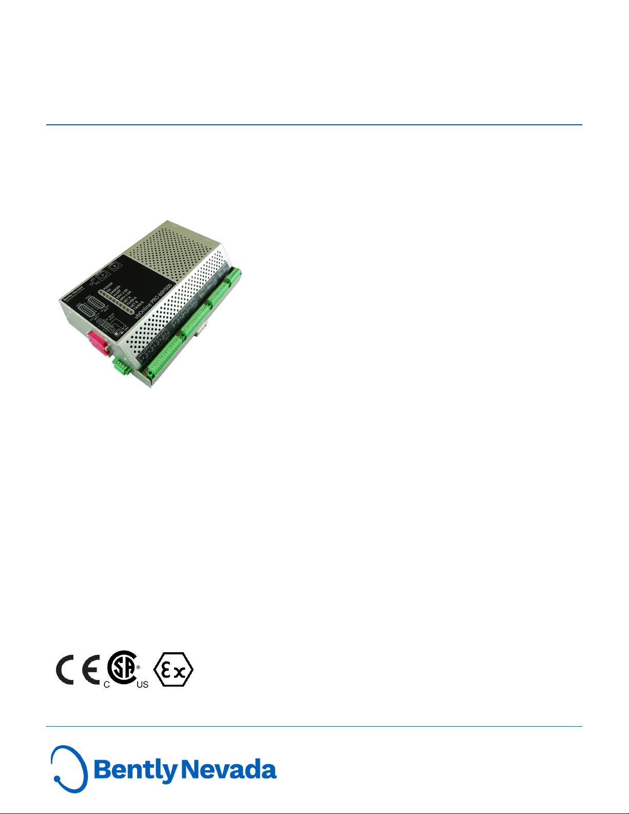
vbOnline Pro Condition Monitoring System
Datasheet
Bently Nevada Machinery Condition Monitoring
Description
The vbOnline Pro Condition Monitoring System uses
sophisticated signal processing algorithms together with
machinery operating states to monitor assets continuously.
This system is part of a condition based maintenance program
that identifies problems before assets begin to fail.
Benefits of the vbOnline Pro Condition Monitoring System are:
n Cost savings from reduced machinery down time
n Early detection of bearing defects
n Reduction of damage to assets
The monitoring system's key features are:
n Signal conditioning
n Alarming
n Speed inputs
n Control system communication
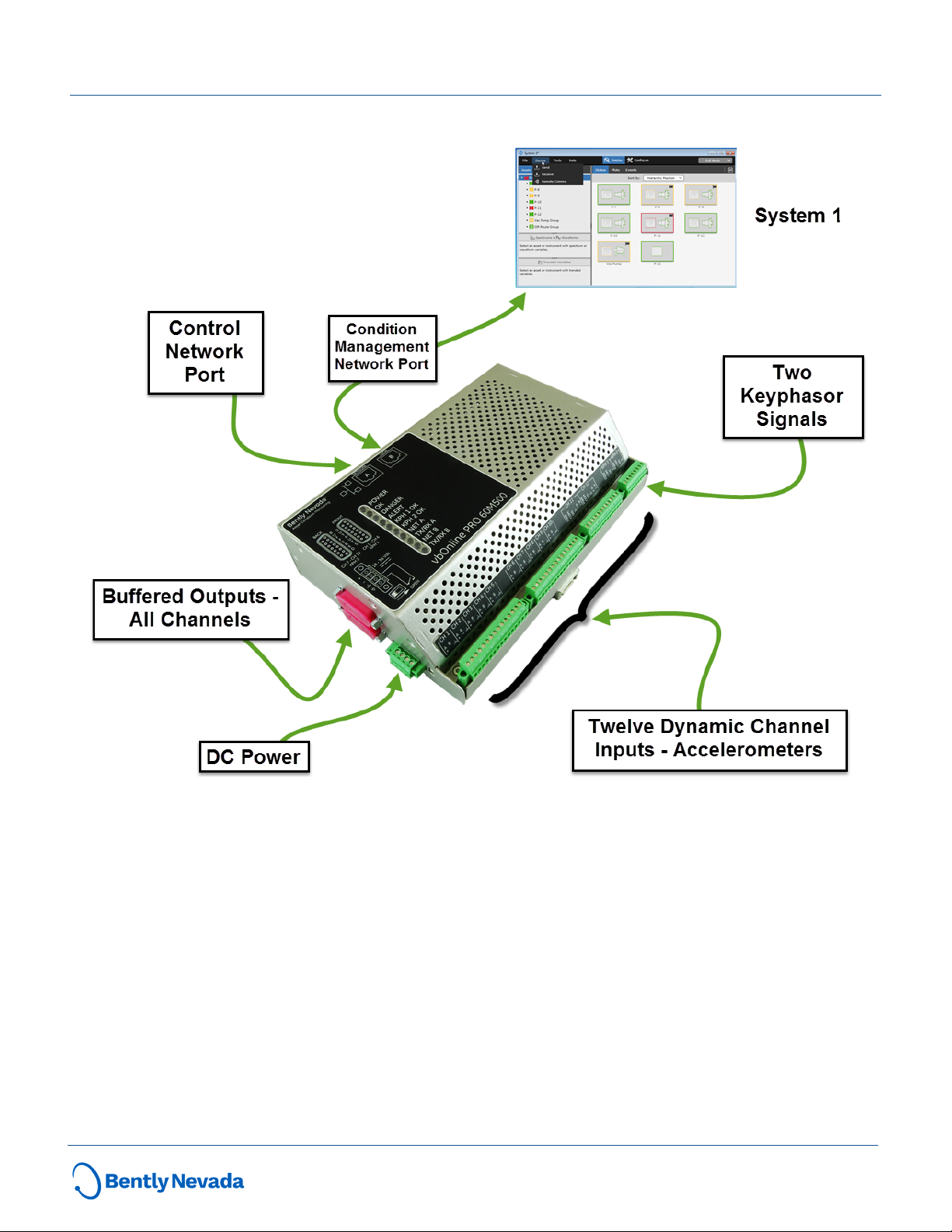
The vbOnline Pro Condition Monitoring System
communicates with System 1 via dual Ethernet connections.
The monitoring system uses 24 bit analog/digital conversion
and 40 kHz bandwidth to monitor rolling element bearing
machinery and gearing.
Sophisticated signal processing algorithms extract
measurement and health indices from each accelerometer
point. The algorithms can be custom tuned to specific bearing
and gear box characteristics.
The vbOnline Pro vbOnline ProCondition Monitoring System
exports trended measurements like direct, bias, speed, gap as
well as channel NOT OK status to third party systems such as
DCS via Modbus over ethernet.
The vbOnline Pro Condition Monitoring System components
are the vbOnline Pro monitor, System 1, Bently Nevada
Monitor Configuration software, transducers, and cables.
Document: 113M5326
Rev. D
Page 2
vbOnline Pro Condition Monitoring System
Datasheet
Figure 1: vbOnline Pro Condition Monitoring System Components
2/10 113M5326 Rev. D
Page 3

vbOnline Pro Condition Monitoring System
Datasheet
on Network B
Specifications
Electrical Specifications
Inputs
Minimum Input
Power
Maximum Input
Power
Maximum Current 1.7 A
Maximum Inrush
Current
Maximum Inputs
Dynamic Range 110 dB @ fs = 102.4 ksps
Signal/Noise Ratio 110 dB @ fs = 102.4 ksps
A/D Conversion
Bandwidth 0 to 40kHz
Outputs
Buffered Signal
Outputs
Two Independent Ethernet Ports
Network A
Network B
Power LED
OK LED
Danger LED Indicates a Danger Alarm condition
Alert LED Indicates an Alert condition
Kph 1 OK LED
Kph 2 OK LED
Net A Indicates Network A has a valid link
TX/RX A
Net B Indicates Network B has a valid link
TX/RX B
18 Vdc
36 Vdc
2.7 A
Less than 5 ms
12 dynamic signals
2 Keyphasor signals
Sigma-Delta
24 bits nominal
Two 15 pin DSUB connector 550 ohm
output impedance
10/100BaseT
Network DHCP Port
10/100BaseT
Local Static IP Port
LEDs
Indicates when a proper power input
is present
Indicates when the system is
functioning properly
Indicates Keyphasor signal 1 is
triggering
Indicates Keyphasor signal 2 is
triggering
Indicates network traffic is flowing
on Network A
Indicates network traffic is flowing
Accuracy
Direct pk or rms ± 1.1%
Bias +0.8 V / -1.34 V
Dynamic Data
Configurable
Synchronous
Waveforms
Spectral Lines 100 to 12,800 in increments of 2X
Spectrum
Frequency Range
Supported
Frequency Range
Spectral Resolution 100 to 12,800 in increments of 2X
Spectrum Window
Types
Demodulation
Bandwidth
Update Rate
Data Storage
Up to 8192 samples
User Configurable up to 40 kHz
0 Hz to 40,000 Hz
Hanning
125 Hz to 10 kHz
18 preset options
Up to once every 10 minutes
User configurable
8 hours
Typical
No alarms
Keyphasor Signal Inputs
Speed Range 1 to 120,000 rpm
1 to 100 rpm ± - 0.1 rpm
Speed Accuracy
100 to 10,000 rpm ± 1 rpm
10,000 to 120,000 rpm ± 10 rpm
Supported Transducers
Acceleration
Channels
Keyphasor Channels
Compatible with constant current
accelerometers
Proximity switches such as
Turck Ni8–M18T–AP6X7M
Bently Nevada Proximity Probes
3/10 113M5326 Rev. D
Page 4

vbOnline Pro Condition Monitoring System
Datasheet
Physical
8.88 X 5.89 X 2.17 inches
Dimensions
Weight
Mounting DIN Rail Mounting
225 X 150 X 55 mm
See "Graphs and Figures" on page7
1.4 kg
3 lbs
Environmental Limits
Operating
Temperature Range
Storage
Temperature Range
Relative Humidity
Pollution Degree
-40 °C to +70 °C
-40 °F to 158 °F
-45 °C to +85 °C
-49 °F to 185 °F
0% to 95% non-condensing for
operation and storage
Pollution Degree 2
Working voltage < 30 Vrms or 60 Vdc
4/10 113M5326 Rev. D
Page 5

vbOnline Pro Condition Monitoring System
Datasheet
SPECIFIC CONDITIONS OF USE:
Compliance and Certifications
For a detailed listing of country- and productspecific approvals, refer to the Approvals Quick
Reference Guide (document 108M1756), at
Bently.com.
EMC
Standards
EN 61000-6-2 Immunity for Industrial
Environments
EMC
EN 61000-6-4 Emissions for Industrial
Environments
Directives
2014/30/EU
Electrical Safety
Standards:
Electrical Safety
EN 61010-1
Directives
2014/35/EU
Hazardous Area Approvals
1. The device shall be installed in an
additional enclosure that provides an
ingress protection rating not less than
IP54 and meets the enclosure
requirements of IEC 60079-0.
2. The equipment shall only be used in an
area of not more than pollution degree 2,
as defined in IEC 60664-1.
3. Transient protection shall be provided
that is set at a level not exceeding 140%
of the peak rated voltage value at the
supply terminals to the equipment.
4. Tightening torque range is 2.0 in-lbf [0.22
N-m] minimum / 2.2 in-lbf [0.25 N-m]
maximum.
WARNING
HAZARDOUS
ENVIRONMENT
DO NOT DISCONNECT OR OPEN
EQUIPMENT UNLESS POWER
HAS BEEN SWITCHED OFF OR
THE AREA IS KNOWN TO BE
NON-HAZARDOUS.
For a detailed listing of country- and productspecific approvals, refer to the Approvals Quick
Reference Guide (document 108M1756), at
Bently.com.
Class I, Zone 2
AEx nA IIC T4 Gc
Class I, Division 2
Groups A, B, C and
CSA/NRTL/C
ATEX/IECEx
D
Install per drawing
115M4822
T4 @ Ta = -40 °C ≤
Ta ≤ +70 °C
II 3 G
Ex nA IIC T4 Gc
Ex ec IIC T4 Gc
Install per drawing
115M4822
T4 @ Ta = -40 °C ≤
Ta ≤ +70 °C
5/10 113M5326 Rev. D
Page 6

vbOnline Pro Condition Monitoring System
Datasheet
Ordering Information
For the detailed listing of country and product specific
approvals, refer to the Approvals Quick Reference
Guide (108M1756) available from www.Bently.com.
60M500 - AA - BB
A: Agency Approvals
00 None
05
B: System 1 License
00 None
01 One
Sensors and Cables
Part Number Description
AS3100S2-Z2
AM3100T2-Z
AP3500T2-Z1
AP3500S2-Z1
330780
330180
330980
200355
287844
284613-050
284613-030
Multi Approvals (CSA, IECEx, ATEX)
Accelerometer, Side Exit
100 mV/g
0.7 - 10,000 Hz
Accelerometer, Top Exit
100 mV/g, 0.4 - 14,000 Hz
Accelerometer, Top Exit
500 mV/g, 0.2 - 2,300 Hz
Accelerometer, Side Exit
500 mV/g, 0.2 - 3,700 Hz
See 3300 XL NSv
Proximity Transducer System
datasheet,
document 147385,and
3300 XL 8mm Proximity Transducer
System datasheet,
document 141194.
3300 XL 11mm Proximity Transducer
System
3300 XL 8mm Proximity Transducer
System
3300 XL NSV Proximity Transducer
System
Low Frequency Accelerometer 100
mV/g
0.2 - 10,000 Hz
Accelerometer Mounting Stud
1/4 -28 to M8x1.25 SST
Accelerometer Cable
15.2 m (50 ft) with straight connector
Accelerometer Cable
9.1 m (30 ft) with straight connector
Part Number Description
Accelerometer Cable
284622-050
284622-030
138131
323314-01
323314-02
15.2 m (50 ft) with right angle
connector
Accelerometer Cable
9.1 m (30ft) with right angle
connector
CAT5 Cable
Minimum cable length is 3 feet.
Maximum cable length is 320 feet.
Cable lengths are 3, 6, 10, 25, 40, 50,
75,
85, 100, 120, 150, 200, 250 and 320
feet.
Buffered output cable
15-pin DSUB to 7 SMA connectors
Buffered output cable
15-pin DSUB to 7 BNC connectors
Accessories
Bently Nevada Monitor
Configuration Software DVD
100M9465-01
BNMC Software is included with
vbOnline Pro Condition Monitoring
System for user administration, IP
configuration and firmware updates.
Miscellaneous
104M2708-01 Spare Power Input Connector
104M3960-01 Spare Input Connector Ch 1-10
104M3961-01 Spare Input Connector Ch 11-12
104M3962-01 Spare Input Connector KPH 1-2
6/10 113M5326 Rev. D
Page 7

vbOnline Pro Condition Monitoring System
Datasheet
Graphs and Figures
Dimensions shown are in inches (millimeters)
Figure 1: vbOnline Pro
7/10 113M5326 Rev. D
Page 8

vbOnline Pro Condition Monitoring System
Datasheet
Figure 2: vbOnline Pro - Side View
Figure 3: vbOnline Pro - Top and Bottom Views
8/10 113M5326 Rev. D
Page 9

vbOnline Pro Condition Monitoring System
Datasheet
Figure 4: Recommended Minimum Clearance Window for Cable Terminations and
Monitor Cooling
9/10 113M5326 Rev. D
Page 10

vbOnline Pro Condition Monitoring System
Datasheet
Copyright 2019 Baker Hughes, a GE company, LLC ("BHGE") All rights reserved.
Bently Nevada, Orbit Logo, Keyphasor and System 1 are registered trademarks of BHGE in the United
States and other countries. All product and company names are trademarks of their respective holders.
Use of the trademarks does not imply any affiliation with or endorsement by the respective holders.
This product may be covered by one or more patents, please see Bently.com/legal for current status.
The information contained in this document is subject to change without prior notice.
1631 Bently Parkway South, Minden, Nevada USA 89423
Phone: 1.775.782.3611 Bently.com
10/10 113M5326 Rev. D
 Loading...