

Page 1
JoyBook S52 System Disassembly Description
Joybook S52 System Disassembly Description
1. Description
Joybook S52 Disassembly can be divided into three main parts. To be more efficient, it is better to get to know more about
disassembly process.
You need the following tools:
- Wiha PicoFinish Slotted Screwdriver (Professional Suggestion)
z Note:
- Crisscross screwdriver, 0×50mm (十字螺絲起子,0×50mm)
- Crisscross screwdriver, 1×60mm
- Flat screwdriver
(一字螺絲起子)
(十字螺絲起子,1×60mm)
- Snipe nose pliers
- Tweezers
- Soft Cushion
- Screws classification box
- Golden type (金色膠帶)
- Screw Torque Document
1. Please turn off Joybook and remove
battery before disassemble.
2. The screw for different components may
very with size.
3. During disassemble process, collect the
screws together with correspondent parts
for avoid mismatch when assemble.
4. Put a soft pad between repair desk and
Joybook to prevent scratch during repair.
5. Void to scrape machine appearance
during disassembly.
Form No:JBS52-DOC-004 - 1 - Confidential □ High ■ Medium □ Low
Page 2
JoyBook S52 System Disassembly Description
2. System Disassembly
The section discusses at length each major component for disassembly/reassembly and show corresponding illustrations. Use another
document “Disassembly Flow Chart” for auxiliary to determine the disassembly sequence for removing components from the notebook.
NOTE: Before you start to install/replace these modules, disconnect all peripheral devices and make sure the notebook is not turned on or
connected to AC power.
1.1.1 Battery Pack
1.1.2 HDD Cover/ HDD Module
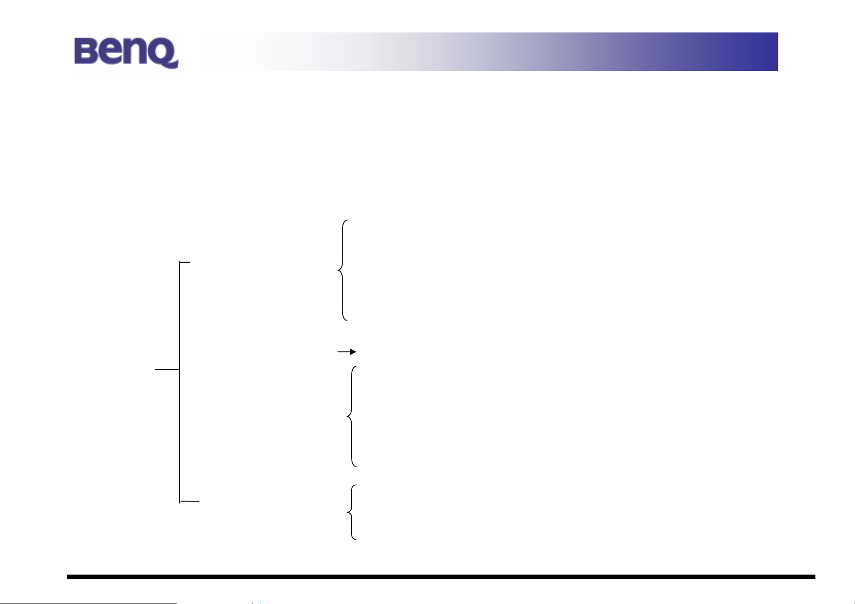
S52
1.Modular Components
2. System Assy
3. LCD ASSY
Top
Base
1.1..3 ODD Module/ ODD Bezel
1.1.4 DDR-SDRAM
1.1.5 WLAN Card
1.1.6 Keyboard Cover/ Keyboard
2.1.1 Top Case/Touchpad Case/ Touchpad cable/ MIC cable
2.2.1 MB
2.2.2 Thermal/ CPU
2.2.3 CRT PCB board / cable
2.2.4 Bluetooth Module
2.2.5 Speakers (L/R)
2.2.6 Bottom Case
3.1.1 LCD Bezel
3.1.2 Hinge Bracket (L/R)
3.1.3 LCD Cover Module
Form No:JBS52-DOC-004 - 2 - Confidential □ High ■ Medium □ Low
Page 3
JoyBook S52 System Disassembly Description
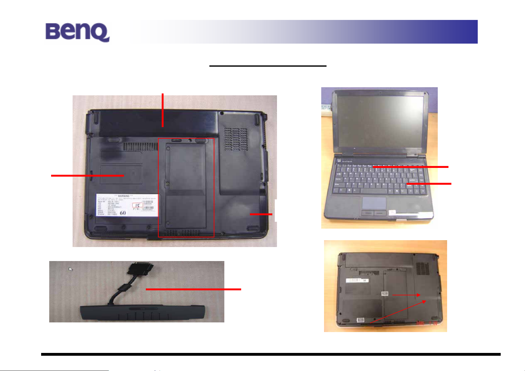
1. Modular Components
You can easily disassemble “Modular components” (as below indication) no need to disassemble main system.
Battery
ODD RAM
MINI PCI
HDD
K/B Cover
K/B
Port-replicator
Seal Label Position
(Option )
Form No:JBS52-DOC-004 - 3 - Confidential □ High ■ Medium □ Low
Page 4

JoyBook S52 System Disassembly Description
1.1.1 Battery Pack
Disassembly
1. Carefully put the notebook upside down.
2. Pull the battery pack out of the compartment ()while sliding and holding the release lever outwards to the
“unlock” ○ position ( n ). (Figure 2-1)
n
Figure 2-1 Remove the battery pack
Battery
Form No:JBS52-DOC-004 - 4 - Confidential □ High ■ Medium □ Low
Page 5
JoyBook S52 System Disassembly Description
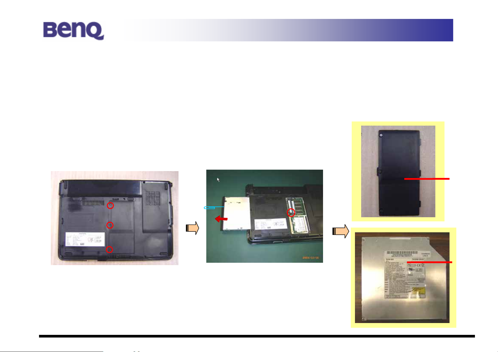
1.1.2 HDD Module
Disassembly
1. Carefully put the notebook upside down. And remove the battery pack. (Refer to section 2.2.1 disassembly)
2. Remove 2 *(item 24) screws fastening the HDD compartment cover (Figure 2-2), and lift the HDD cover up. (Figure
2-3).
3. Pull the HDD module right forward from the system.
Figure 2-2 Remove the HDD cover Figure 2-4 Pull the HDD drive out
Figure 2-3 HDD cover
HDD Cover
Form No:JBS52-DOC-004 - 5 - Confidential □ High ■ Medium □ Low
Page 6

JoyBook S52 System Disassembly Description
4. Refer to step3, remove 4 *(item 23) screws to separate the HDD module from the HDD case. (Figure 2-4).
HDD case
HDD module
Figure 2-4 Free the HDD drive
Form No:JBS52-DOC-004 - 6 - Confidential □ High ■ Medium □ Low
Page 7
JoyBook S52 System Disassembly Description
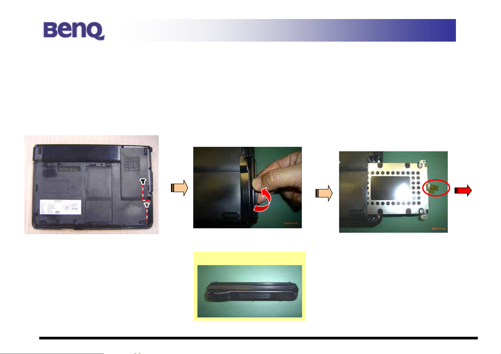
1.1.3 ODD Module (Configuration: DVD & CD-RW Combo/ DVD+RW/ DVD Super-Multi)
Disassembly
1. Carefully put the notebook upside down. And remove the battery pack. (Refer to section 2.1.1 disassembly)
2. Put the notebook back to the upright position. Loosen the 3 screws () to release RAM Door. (Figure 2-5).
3. Then insert a small rod, such as a straightened paper clip, into the drive’s manual eject hole and push firmly to release
the tray (o). Pull the tray out until fully extended (), then carefully pull harder to remove the ODD Module. (Figure
2-6)
Figure 2-5 Remove the ODD Module
n
Figure 2-6 Remove the ODD Module
RAM
Door
ODD
Module
Form No:JBS52-DOC-004 - 7 - Confidential □ High ■ Medium □ Low
Page 8
JoyBook S52 System Disassembly Description
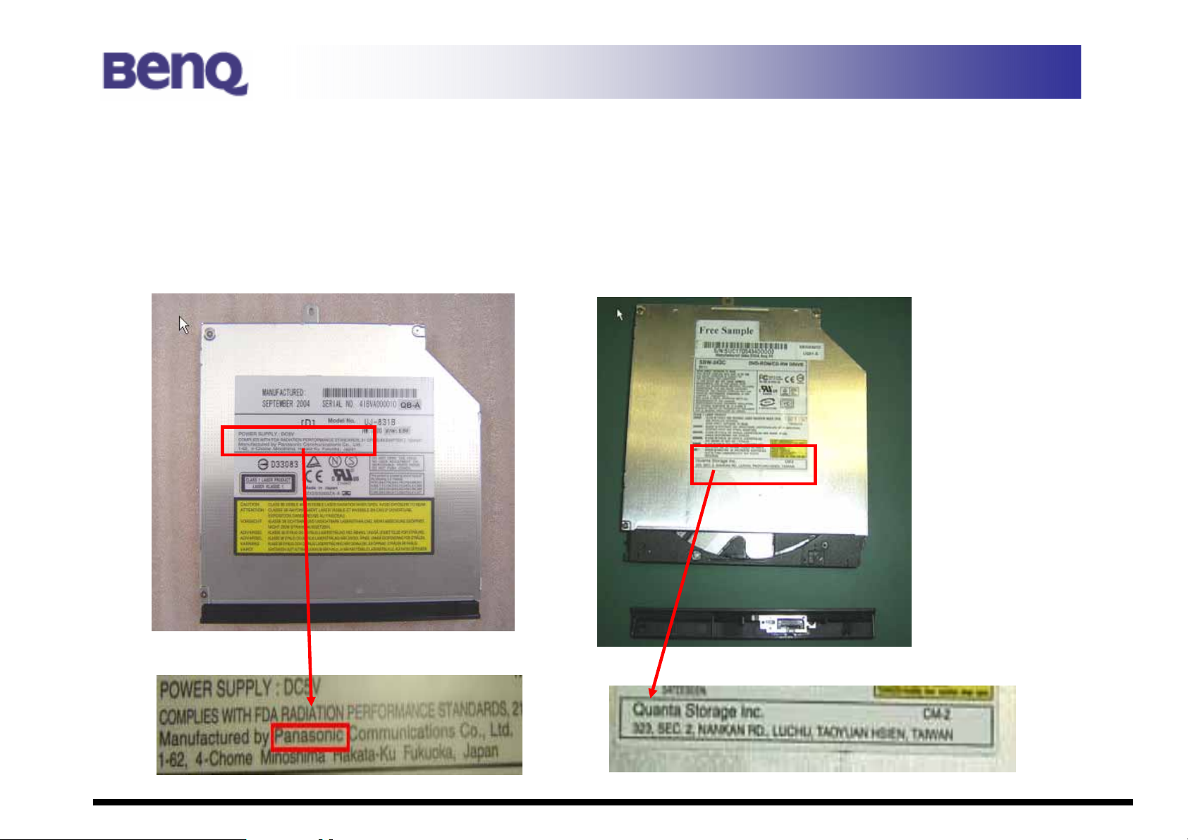
ODD Bezel
There are 2 kinds of bez el includes of GBAS (Quanta) and KME (Panasonic).
※How to adjust what kind of your ODD?
KME (Panasonic) GBAS (Quanta)
Form No:JBS52-DOC-004 - 8 - Confidential □ High ■ Medium □ Low
Page 9
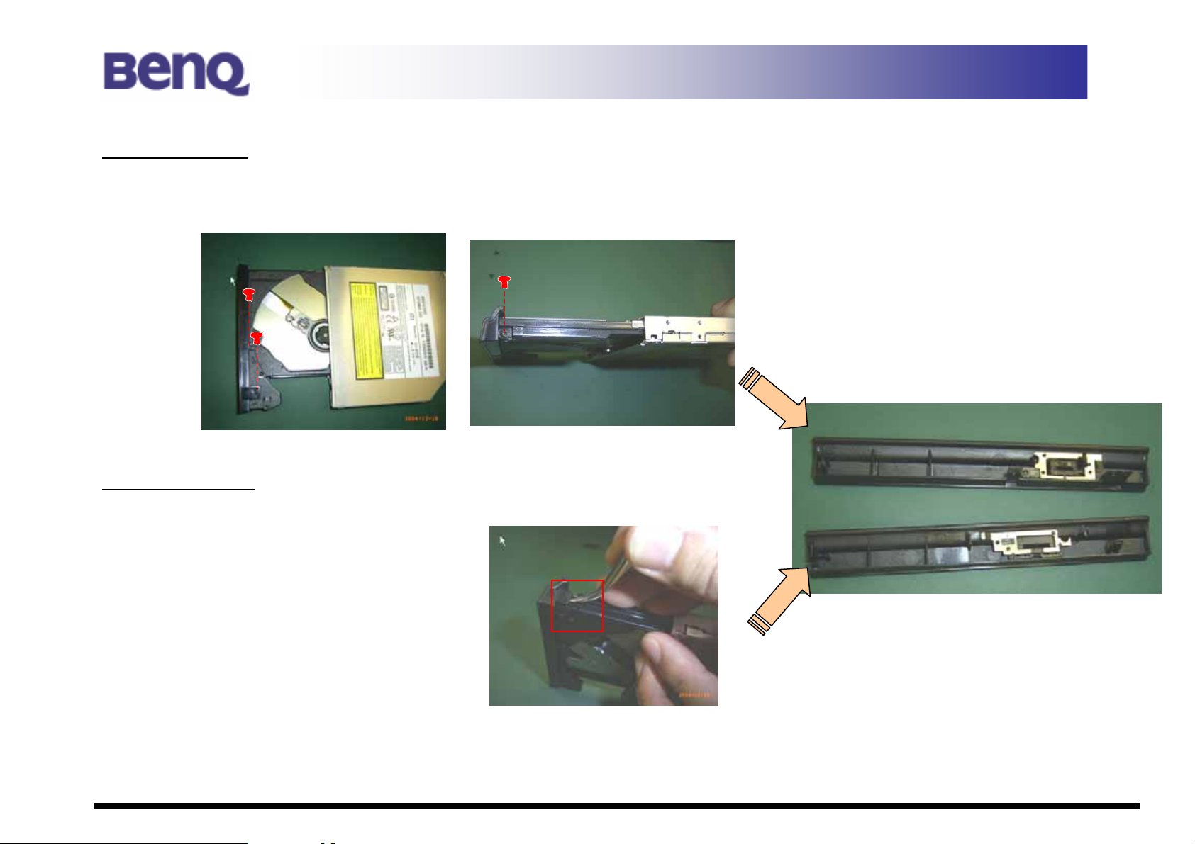
KME Disassembly
1. Refer to section 2.1.3 (o) step.
JoyBook S52 System Disassembly Description
2. Remove 3 screws (item 25) as the indication. (
Figure 2-7)
Figure 2-7 Remove 3 screws
GBAS Disassembly
1. Turn the ODD to leftside. And push forward the bezel with
as the indication to release it.
(Figure 2-8)
tweezers lightly
Figure 2-8 push with tweezers
Form No:JBS52-DOC-004 - 9 - Confidential □ High ■ Medium □ Low
Page 10

JoyBook S52 System Disassembly Description
1.1.4 DDR-SDRAM
Disassembly
1. Refer to section 2.1.3 disassembly () step to remove Door. (Figure 2-9)
2. Pull the retaining clips outwards (n) and remove the DDR-SDRAM from the socket (o).(Figure 2-10)
Figure 2-9 Remove the cover first Figure 2-10 Remove the DDR-SDRAM
Reassembly
To install the DDR, match the DDR's notched part with the socket's projected part and firmly insert the DDR into
the socket at 20-degree angle. Then push down until the retaining clips lock the DDR into position.
Form No:JBS52-DOC-004 - 10 - Confidential □ High ■ Medium □ Low
Page 11

JoyBook S52 System Disassembly Description
1.1.5 Wireless Card
Disassembly
1. Refer to section 2.1.3 disassembly () step to remove the door. (Figure 2-11)
2. Disconnect 2 wireless card’s antennae first. Then pull the retaining clips outwards. (Figure 2-12)
Disconnect Antenna
1. White connect to “AUX”
2. Black connect to “Main”
WLAN Module
Figure 2-11 Remove the RAM Door first Figure 2-12 Remove wireless card
Form No:JBS52-DOC-004 - 11 - Confidential □ High ■ Medium □ Low
Page 12

JoyBook S52 System Disassembly Description
1.1.6 Keyboard Cover/ Keyboard
Disassembly
1. Refer to 2.1.1.section to remove Battery Pack first.
2. Remove 3 / 1 / 1 screws (Figure 2-13)
3. Reverse the machine to the rear side. Then remove 2 screws.
Open the LCD to level plane. Slightly lift up the keyboard cover. (Figure 2-14)
4.
Bottom Battery
Mylar (Black)
******* Screw type *******
-- 3screw (item 18)
-- 1 screw (item 19)
-- 1 screw (item 17)
-- 2 screw (item 20.21)
Figure2-14 Lift up the K/B Cover
Keyboard Cover
5. Remove 1* (item 16) , 1 * (item 15) screw then
Form No:JBS52-DOC-004 - 12 - Confidential □ High ■ Medium □ Low
Figure 2-13 Remove 7 screws
upside down to remove 1* (item 14) screw.
Page 13

JoyBook S52 System Disassembly Description
Remove 1 / 1 / 1 screws and lift up the K/B
Then disconnect the cable to release keyboard. (Figure 2-16)
Figure 2-15 remove 3 screws and lift up the K/B
*****Screw type *******
-- 1 screw (item 16)
-- 1 screw (item 15)
-- 1 screw (item 14)
Be careful to remove the
K/B slightly in case of the
wedge
Keyboard
Figure 2-16 disconnect the cable and detach the keyboard
Form No:JBS52-DOC-004 - 13 - Confidential □ High ■ Medium □ Low
Page 14

JoyBook S52 System Disassembly Description
Separate (2)System ASSY & (3)LCD Module
1. Refer to 1.1.5 Section to disconnect wireless antenna first.
2. Open the LCD cover to level plane. And disconnect 4 cables (LCD Cable/ VGA Cable/ Touchpad Cable/ Antenna) from the
motherboard. Then remove 4 *(item 13) on hinges. (Figure 2-17)
1 LCD Cable
2 Lift up Antenna
Figure 2-17 Disconnect 4 cables and remove two hinge covers with screwdriver
Form No:JBS52-DOC-004 - 14 - Confidential □ High ■ Medium □ Low
3 Touch Pad Cable
4VGA Cable
Page 15

JoyBook S52 System Disassembly Description
Antenna Assembly Notice
Please remember let 2 antenna cables to be “parallel”
and put into the trench as the picture then fix it with
golden type.
If not do so, it may will make some issue.
2. Put the antenna into the hole of motherboard.
3. Pass through to connect to WLAN Card.
Form No:JBS52-DOC-004 - 15 - Confidential □ High ■ Medium □ Low
Page 16

2.1 Top Case (with touchpad module & MIC cable)
JoyBook S52 System Disassembly Description
1. Refer to section 2.1.6 to disassemble keyboard first.
2. Put the notebook upside down. Remove 9*( item7. 8) / 2*(item 2)
screws t
hat secure the bottom case. Remove 2 * (item 21) screws in the rear of the
notebook.. (Figure 2-18)
Then lift the bottom case from the rack and disconnect the MIC cable of top
case (Figure 2-19)
Base ASSY
Figure 2-19 disconnect MIC cable
Top case with MIC and touchpad
MIC cable
Touch Pad
Figure 2-18 Remove 13 screws and lift up the case
Form No:JBS52-DOC-004 - 16 - Confidential □ High ■ Medium □ Low
Page 17

JoyBook S52 System Disassembly Description
How to disassemble “Touchpad” & “MIC cable” from Top Case?
1. Remove the upper 2* (item 26); lower 2* (item 27) as blue circle of the top case to remove touch pad case () .
Then you can disconnect the touch pad cable ().
2. Remove the “MIC cable” refer to red arrow indication. (Figure 2-20)
Touchpad case
Touchpad cable
MIC cable
Figure 2-20 remove MIC cable & Touchpad case/ cable
Form No:JBS52-DOC-004 - 17 - Confidential □ High ■ Medium □ Low
Page 18

JoyBook S52 System Disassembly Description
2.2 Base ASSY
2.2.1 Mother Board
1. Refer to section 2.2.1
2. T o disconnect 3 cable : L/R speaker cable & bluetooth cable as indication. (Figure 2-21)
3. Remove 4* (item 5) / 2* (item 4) screws. Then Lift up the mother board carefully. (Figure 2-22)
Left Speaker cable
Please paste the golden
Bluetooth
type on cable as
assembly.
Right Speaker cable
Figure 2-22 Lift up the M/B
Form No:JBS52-DOC-004 - 18 - Confidential □ High ■ Medium □ Low
Page 19

2.2.2 Thermal Module/ CPU
1. Reverse the mother board and loosen 3 * (item 1) and disconnect 1 cable.
Then can release the thermal module. (Figure 2-23)
JoyBook S52 System Disassembly Description
Please secure the thermal by
the sequence as 1,2,3
indication on the thermal
interface.
2. Loosen the screw by a flat screw driver, upraise the CPU socket to unlock the CPU. (Figure 2-24)
Figure 2-23 release the thermal
Thermal
Form No:JBS52-DOC-004 - 19 - Confidential □ High ■ Medium □ Low
Figure 2-24 detach the CPU socket
n
Page 20

JoyBook S52 System Disassembly Description
Refer to 2.2.2 remove thermal and CPU of the M/B.That it will be the M/B Unit.
Mylar
Modem Board
Intel Chipset
Centrino 915GM
North Bridge
Form No:JBS52-DOC-004 - 20 - Confidential □ High ■ Medium □ Low
Page 21

JoyBook S52 System Disassembly Description
How to disassemble PCMCIA from M/B?
1. Remove the 2 *(item 28) screws that secure the PCMCIA then reverse M/B to another side. (Figure 2-25)
2. Remove PCMCIA carefully refer to red indication with flat screwdriver. (Figure 2-26)
Disassembly PCMCIA Notice
Figure 2-26 push from inner to outer with
flat screwdriver as indication
Figure2-25 remove 2 screws
Be careful not to push
the HDD connector’s
pin too strongly.
Form No:JBS52-DOC-004 - 21 - Confidential □ High ■ Medium □ Low
Page 22

2.2.3 CRT PCB Module
JoyBook S52 System Disassembly Description
Disassembly
1. Refer to 2.2.3 to remove M/B.
2. Remove 1*(item 3) / 2 hex nuts (item 9) and disconnect the cable
as the blue arrow to remove VGA cable and VGA board.
(Figure 2-26)
Assembly Notice:
Please arrange the cable by the trench road of the
case as picture.
CRT Cable Assembly Notice:
CRT Cable CRT PCB
Figure 2-26 remove VGA module
Figure 2-26 Re move VGA module
Form No:JBS52-DOC-004 - 22 - Confidential □ High ■ Medium □ Low
Page 23

2.2.4 Bluetooth Module
Disassembly
1. Refer to 2.2.3 to remove M/B.
2. Remove 2 * (item 2) then detach Bluetooth Module. (Figure 2-26)
JoyBook S52 System Disassembly Description
Bluetooth Module
Figure 2-26 remove 2 screws to release bluetooth module
Form No:JBS52-DOC-004 - 23 - Confidential □ High ■ Medium □ Low
Page 24

JoyBook S52 System Disassembly Description
2.2.5 Speakers
Disassembly
1. Refer to 2.2.3 to remove M/B.
2. Remove 2* (item 29) screws then detach the right and left speakers. (Figure 2-27)
Right Speaker
Left Speaker
Figure 2-27 remove 2 screws to release speakers
Form No:JBS52-DOC-004 - 24 - Confidential □ High ■ Medium □ Low
Page 25

JoyBook S52 System Disassembly Description
2.2.6 Bottom Case
1. Refer to section 2.2.4, 2.2.5, 2.2.6 to remove all components on Bottom case.
You will get bottom case. (Figure 2-28)
Ventilation
Hole
IR
Form No:JBS52-DOC-004 - 25 - Confidential □ High ■ Medium □ Low
Ventilation
Hole
Figure 2-28 S52 bottom case
Ventilation
Hole
Page 26

1. Refer to section 2.1.6 to separate LCD module. (Figure 2-29)
JoyBook S52 System Disassembly Description
3. LCD Module
Figure 2-29 S52 LCD Module
Form No:JBS52-DOC-004 - 26 - Confidential □ High ■ Medium □ Low
Page 27

3.1.1 LCD Bezel
Disassembly
1. Refer to section 3.1
JoyBook S52 System Disassembly Description
2. Remove the rubber
7 pads and 7 * (item 12) screws on the corners of the panel. (Figure 2-30)
3. Remove LCD Bezel by hand. (Direction: Inside to outside as indication)
LCD Bezel
Figure 2-30 remove rubber and screws
Form No:JBS52-DOC-004 - 27 - Confidential □ High ■ Medium □ Low
Page 28

JoyBook S52 System Disassembly Description
3.1.2 LCD Inverter/ Bracket/ Panel/ FFC
Disassembly
1. Remove the 6* (item 11) screws of LCD panel. (Figure 2-31)
2. Disconnect 2 cable from the inverter board to detach inverter. (Figure 2-32)
Figure 2-31 remove 6 screws to release LCD assy
Figure 2-32 LCD Inverter
Form No:JBS52-DOC-004 - 28 - Confidential □ High ■ Medium □ Low
Page 29

JoyBook S52 System Disassembly Description
2. Remove the 4 *(item 10) screws to remove the LCD bracket on side of the LCD panel. (Figure 2-33)
Figure 2-33 LCD Bracket
3. Reverse the LCD panel. To tear open the silver tinfoil and remove LCD FFC. (Figure 2-34)
LCD Panel (front side)
Form No:JBS52-DOC-004 - 29 - Confidential □ High ■ Medium □ Low
Figure 2-34 LCD FFC
Page 30

JoyBook S52 System Disassembly Description
3.1.3 LCD Cover Module
Disassembly
1. Completion of 3.1.1 disassembly section. You can get LCD Cover Module. It includes of Antenna and LCD Support.
(Figure 2-35)
Mylar
Figure 2-35
Form No:JBS52-DOC-004 - 30 - Confidential □ High ■ Medium □ Low
LCD cover module
Page 31

JoyBook S52 System Disassembly Description
How to disassemble LCD Support / Wi re Antenna from “LCD cover module”?
1. Refer to section 3.1.2.
2. Release 6 * (item 30) as the arrow on support to remove “LCD support” . (Figure 2-36)
and lift all type to remove “wire antenna with bracket”. (Figure 2-37)
Figure 2-36
LCD Support
Figure 2-37
Wire antenna with bracket
Form No:JBS52-DOC-004 - 31 - Confidential □ High ■ Medium □ Low
 Loading...