

Page 1

Product System (PS)
Subject:
Doc. No.
Project Code:
Model Name:
C4-425 Trouble Shooting Guide
99.K4501.001
DHS5
Part No.:
Component Part.
No.:
99.K4501.000
99.K4501.000-C4-425-001
NA
Rev.: 0
Page 1 of 35
JoybookS52 Trouble Shooting Guide
Form No: BQY0-0B-003-32(031205)
1
Page 2
Product System (PS)
Subject:
Doc. No.
Project Code:
Model Name:
C4-425 Trouble Shooting Guide
99.K4501.001
DHS5
Part No.:
Component Part.
No.:
99.K4501.000
99.K4501.000-C4-425-001
NA
Rev.: 0
Page 2 of 35
Contents
1.1 Outline...........................................................................................................................5
1.2 Basic Flowchart............................................................................................................5
1.3 Power Supply..............................................................................................................10
Procedure 1 Power Icon Check...........................................................................10
Procedure 2 Connection Check...........................................................................12
Procedure 3 Battery Replacement Check ...........................................................12
Procedure 4 Replacement Check ........................................................................12
1.4 System Board..............................................................................................................13
Procedure 1 Port 80 Check (in Boot Mode) .......................................................13
Procedure 2 Port 80 Check (in Resume Mode) ..................................................17
Procedure 3 Test Program Check........................................................................18
Procedure 4 Replacement Check ........................................................................18
1.5 2.5-inch HDD..............................................................................................................19
Procedure 1 Message Check ...............................................................................19
Procedure 2 Partition Check .............................................................................20
Procedure 3 Format Check..................................................................................20
Procedure 4 Test Program Check........................................................................21
Procedure 5 Connector Check and Replacement Check.....................................21
1.6 Keyboard ....................................................................................................................23
Procedure 1 Test Program Check........................................................................23
Procedure 2 Connector Check and Replacement Check.....................................23
1.7 Display.........................................................................................................................24
Procedure 1 Test Program Check........................................................................24
Procedure 2 Connector Check and Replacement Check.....................................24
1.8 DVD-ROM Drive .......................................................................................................26
Procedure 1 DVD-ROM Cleaning Check...........................................................26
Procedure 2 Test Program Check........................................................................26
Form No: BQY0-0B-003-32(031205)
2
Page 3

Product System (PS)
Subject:
Doc. No.
Project Code:
Model Name:
C4-425 Trouble Shooting Guide
99.K4501.001
DHS5
Part No.:
Component Part.
No.:
99.K4501.000
99.K4501.000-C4-425-001
NA
Rev.: 0
Page 3 of 35
Procedure 3 Connector Check and Replacement Check.....................................26
1.9 CD_ROM Drive ......................................................................................................28
Procedure 1 CD_ROM Cleaning Check .............................................................28
Procedure 2 Test Program Check........................................................................28
Procedure 3 Connector Check and Replacement Check.....................................28
1.10 Cooling Module ..........................................................................................................30
Procedure 1 Test Program Check........................................................................30
Procedure 2 Connector Check and Replacement Check.....................................30
1.11 Touch Pad ...................................................................................................................31
Procedure 1 Test Program Check
Procedure 2 Connector and FCC Check and Replacement Check
1.12 Audio ...........................................................................................................................32
Procedure 1 Test Program Check
Procedure 2 Connector Check and Replacement Check
1.13 IR .................................................................................................................................33
Procedure 1 Test Program Check
Procedure 2 Replacement Check
1.14 Battery life (Battery Learning).................................................................................34
Form No: BQY0-0B-003-32(031205)
3
Page 4

Product System (PS)
Subject:
Doc. No.
Project Code:
Model Name:
C4-425 Trouble Shooting Guide
99.K4501.001
DHS5
Part No.:
Component Part.
No.:
99.K4501.000
99.K4501.000-C4-425-001
NA
Rev.: 0
Page 4 of 35
Figures
Figure 1-1 Basic flowchart (1/2) .........................................................................................7
Figure 1-2 Basic flowchart (2/2) .........................................................................................8
Tables
Table 1-1 Port 80 LED boot mode status (1/3) ................................................................14
Table 1-2 Port 80 LED resume mode status.....................................................................17
Table 1-3 HDD error code and status...................................................................................
Form No: BQY0-0B-003-32(031205)
4
Page 5

Product System (PS)
Subject:
Doc. No.
Project Code:
Model Name:
C4-425 Trouble Shooting Guide
99.K4501.001
DHS5
Part No.:
Component Part.
No.:
99.K4501.000
99.K4501.000-C4-425-001
NA
Rev.: 0
Page 5 of 35
1.1 Outline
This chapter describes the fault diagnosis procedures for field replaceable units (FRUs) in the computer.
The FRUs covered here are as follows:
1. System board 2. 2.5-inch HDD 3. Keyboard
4. Display 5. DVD-ROM drive 6. CD_ROM drive
7. Cooling module 8. Touch Pad 10. Audio
11. IR 12. Battery life (Battery Learning)
See Tear Down guide for the procedures to replace FRUs and Diagnostic manual for the procedures to use
test programs
The following tools are required to perform the diagnostic procedures:
1. Diagnostics (maintenance test program) bootable CD
2. Screwdrivers
3. Cleaning disk kit (for ODD drive cleaning)
4. Port 80 card
5. Multi-meter
6. Headphone
7. Microphone
8. External FDD attachment
1.2 Basic Flowchart
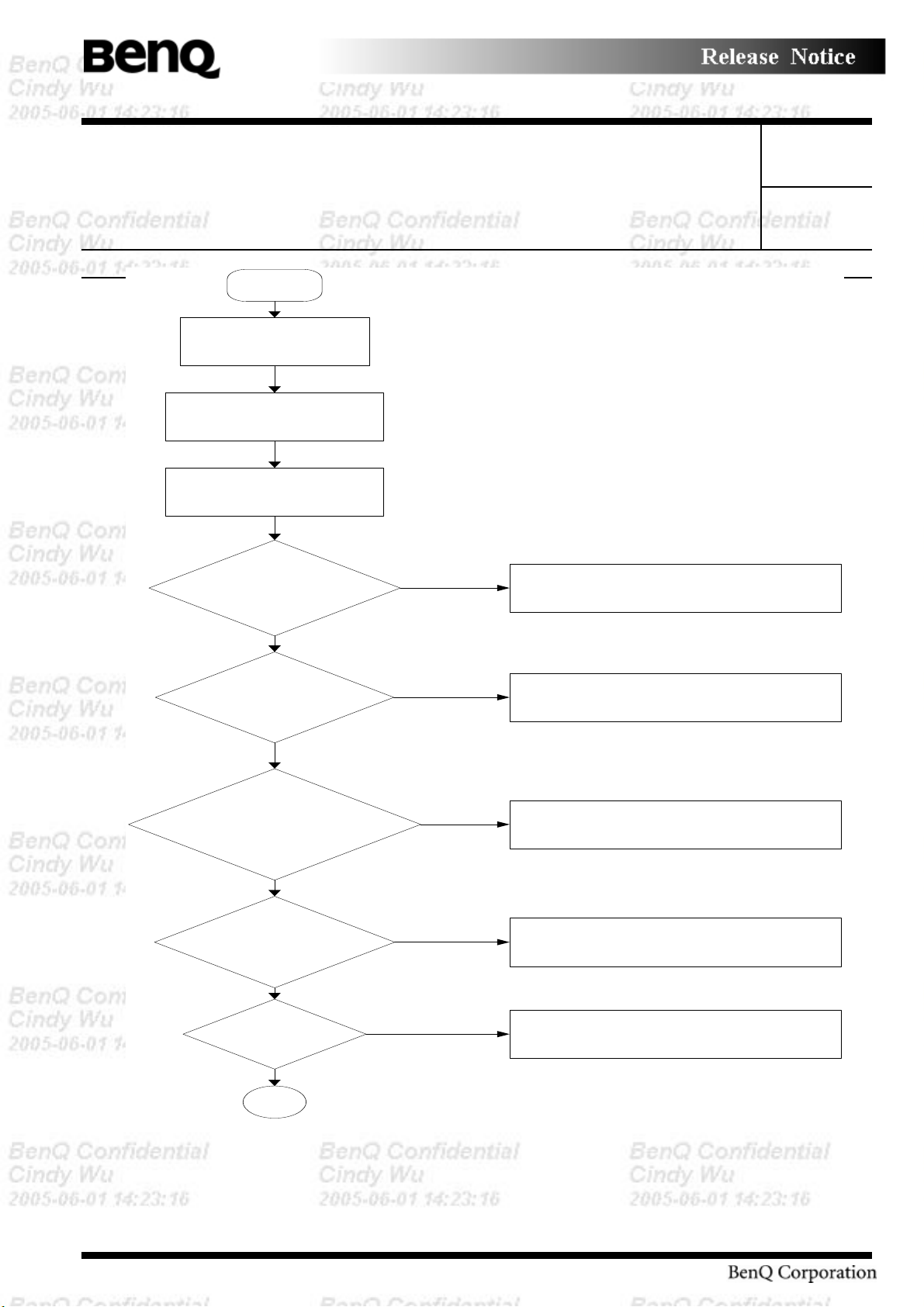
The basic flowchart in Figure 2-1 serves as a guide for identifying a possibly faulty FRU.
Form No: BQY0-0B-003-32(031205)
5
Page 6

Product System (PS)
Subject:
Doc. No.
Project Code:
Model Name:
C4-425 Trouble Shooting Guide
99.K4501.001
DHS5
Part No.:
Component Part.
No.:
99.K4501.000
99.K4501.000-C4-425-001
NA
Rev.: 0
Page 6 of 35
Before going through the diagnostic flowchart steps, verify the following:
Ask the user if a password has been registered and, if so, ask him or her to enter the password. If
the user has forgotten the system password, use a jump wire to make a short circuit on pad 10
that’s near mini PCI slot, then turn the power on. When booted, the computer overrides password
protection and automatically erases the current password. Please remove the short circuit on pad
10 when the password erased.
Make sure the BenQ version of Windows® 2000, or XP has been installed on the HDD. Any
other operating system can cause the computer to malfunction.
Make sure any piece of optional equipment has been installed.
Form No: BQY0-0B-003-32(031205)
6
Page 7
Product System (PS)
Subject:
Doc. No.
Project Code:
Model Name:
C4-425 Trouble Shooting Guide
99.K4501.001
DHS5
Start
Part No.:
Component Part.
No.:
Connect the AC
Adapter
Insert Bootable CD
into CD-ROM
Turn the Power on
and boot from CD
Power LED on ??
NO
99.K4501.000
99.K4501.000-C4-425-001
NA
Rev.: 0
Page 7 of 35
Follow the power supply
diagnostic procedure in
section2.3
YES
Battery LED on ??
YES
Message
“BenQ”displayed??
YES
“Password=”
displayed
YES
OS start??
YES
1
Follow the power supply
diagnostic procedure in
NO
section2.3
Follow the display diagnostic
procedure in section 2.4 &
NO
2.7
See the previous page to
NO
delete the password
Follow the HDD diagnostic
procedure in section 2.5
NO
Form No: BQY0-0B-003-32(031205)
Figure -1 Basic flowchart (1/2)
7
Page 8

Product System (PS)
Subject:
Doc. No.
Project Code:
Model Name:
C4-425 Trouble Shooting Guide
99.K4501.001
DHS5
Part No.:
Component Part.
No.:
1
Diagnostic Program
loaded??
YES
NO
Perform each test with
diagnostic program.
99.K4501.000
99.K4501.000-C4-425-001
NA
Rev.: 0
Page 8 of 35
Follow the CD-ROM diagnostic
Procedures in section 2.9
Identify the test resulting in the
Any error detected by the
diagnostic program??
NO
YES
error and perform the
appropriate diagnostic
procedures
The system is
normal.
END
Figure -2 Basic flowchart (2/2)
Form No: BQY0-0B-003-32(031205)
8
Page 9
Product System (PS)
Subject:
Doc. No.
Project Code:
Model Name:
C4-425 Trouble Shooting Guide
99.K4501.001
DHS5
Part No.:
Component Part.
No.:
99.K4501.000
99.K4501.000-C4-425-001
NA
Rev.: 0
Page 9 of 35
If the diagnostic program cannot detect an error, the error may be intermittent. Run the continuous test
program repeatedly to isolate the problem. Check the log utilities function to confirm which diagnostic
test detected the error, then perform the appropriate troubleshooting procedures as follows:
1. If an error is detected by the System test, Memory test or Real Timer test, follow the system board
troubleshooting procedures in Section 1.4.
2. If an error is detected by the Hard Disk test, follow the HDD troubleshooting procedures in
Section 1.5.
3. If an error is detected by the Keyboard test, follow the keyboard troubleshooting procedures in
Section 1.6.
4. If an error is detected by the Display test, follow the display troubleshooting procedures in Section
1.7.
5. If an error is detected by the DVD-ROM test, follow the DVD-ROM troubleshooting procedures
in Section 1.8.
6. If an error is detected by the CD-ROM test, follow the CD-ROM troubleshooting procedures in
Section 1.9.
7. If an error is detected by the Fan On/Off test, follow the cooling module troubleshooting
procedures in Section 1.10
8. If an error is detected by the Touch Pad test, follow the Touch Pad troubleshooting procedures in
Section 1.11
9. If an error is detected by the audio function test, follow the Audio function troubleshooting
procedures in Section 1.12
10. If an error is detected by the IR test, follow the IR troubleshooting procedures in Section 1.13
11. If an error is detected by the Extending Battery life (Battery Learning), follow the Extending
Battery life procedures in Section 1.14
Form No: BQY0-0B-003-32(031205)
9
Page 10
Product System (PS)
Subject:
Doc. No.
Project Code:
Model Name:
C4-425 Trouble Shooting Guide
99.K4501.001
DHS5
Part No.:
Component Part.
No.:
99.K4501.000
99.K4501.000-C4-425-001
NA
Rev.: 0
Page 10 of 35
1.3 Power Supply
The power supply in the computer controls many functions and components. To check if the power supply
is defective or malfunctioning, follow the troubleshooting procedures below as instructed.
Procedure 1 Power Icon Check
Procedure 2 Connection Check
Procedure 3 Replacement Check
Procedure 1 Power Icon Check
The following two power LEDs indicate the power supply status:
Battery LED
Power LED
The power supply controller displays the power supply status through the Battery and Power LEDs as in
the tables below.
Battery LED
Battery LED Power supply status
On in orange Battery being charged
Blinking in orange battery is abnormal
Blinking in blue Battery low while driving the computer *1
On in blue Battery is in use for system on
Off Battery fully charged, with AC adapter connected
*1: Battery power will run out in just a few minutes.
Form No: BQY0-0B-003-32(031205)
10
Page 11
Product System (PS)
Subject:
Doc. No.
Project Code:
Model Name:
C4-425 Trouble Shooting Guide
99.K4501.001
DHS5
Part No.:
Component Part.
No.:
99.K4501.000
99.K4501.000-C4-425-001
NA
Rev.: 0
Page 11 of 35
POWER LED
Power LED Power supply status
On in blue System fully on
On in orange System in suspend
Off System in power off
If power LED is on in blue, but nothing appear on screen. Please refer to section 2.4 System Board and
section 2.7 Display for troubleshooting.
If the Power LED off while turn on the power, follow the steps below:
1. Remove the battery pack and the AC adapter to shut off power supply to the computer.
2. Attach the battery and AC adapter back and turn on the power again. If the LED still off, follow
the steps below:
Check 1 Make sure the Power LED goes on in blue. If it does not, go to Procedure 2.
Check 2 Make sure the Battery LED goes on in blue without AC adapter. If it does not, go to
Procedure 4.
Check 3 Make sure the Battery LED goes on in orange when battery gauge is not full. If it does not,
go to Procedure 4.
Check 4 Make sure the Battery LED blinks in orange, go to Procedure 3.
Form No: BQY0-0B-003-32(031205)
11
Page 12

Product System (PS)
Subject:
Doc. No.
Project Code:
Model Name:
C4-425 Trouble Shooting Guide
99.K4501.001
DHS5
Part No.:
Component Part.
No.:
Procedure 2 Connection Check
Power is supplied to the system board as illustrated below:
AC
adaptor
AC power cord
AC adaptor cord
99.K4501.000
99.K4501.000-C4-425-001
NA
System board
Battery pack
Rev.: 0
Page 12 of 35
Follow the steps below to check whether each connector has been connected correctly:
Check 1 Make sure the AC adaptor and AC power cord have been firmly plugged into the DC IN
18V socket and wall outlet, respectively. When they have been connected correctly,
perform Check 2.
Check 2 Connect a new AC adaptor and AC power cord.
• If the Power LED does not go on while turn on the power, go to Procedure 4.
• Disconnect AC adapter and turn on the power. If the battery LED does not go on,
perform Check 3.
Check 3 Make sure the battery pack has been correctly installed in the computer. If the battery LED
does not go on while the battery pack has been installed correctly, go to Procedure 4.
Procedure 3 Battery Replacement Check
The Battery may be faulty. Replace the battery pack with a new one following Tear Down guide. If the
battery LED does not go on in blue or orange, go to Procedure 4.
Procedure 4 Replacement Check
The system board, charger board, or CPU may be faulty. Disassemble the computer according to Tear
Down guide and follow the steps below:
Check 1 Replace the charger board with a new one. If the battery pack is still not working properly,
perform Check 2.
Check 2 Replace the system board with a new one. If the battery pack is still not working properly,
perform Check 3.
Check 3 Replace the CPU with a new one
Form No: BQY0-0B-003-32(031205)
12
Page 13

Product System (PS)
Subject:
Doc. No.
Project Code:
Model Name:
C4-425 Trouble Shooting Guide
99.K4501.001
DHS5
Part No.:
Component Part.
No.:
99.K4501.000
99.K4501.000-C4-425-001
NA
Rev.: 0
Page 13 of 35
1.4 System Board
To check if the system board is defective or malfunctioning, follow the troubleshooting procedures below
as instructed.
Procedure 1 Port 80 Check (in Boot Mode)
Procedure 2 Port 80 Check (in Resume Mode)
Procedure 3 Test Program Check
Procedure 4 Replacement Check
Procedure 1 Port 80 Check (in Boot Mode)
The port 80 card LED displays the POST status and error status by turning lights on and off as 2
hexadecimal value obtained in the boot mode after the system unit is switched on.
Follow the steps below to use the printer port LED:
1. Turn on the computer and set the boot mode.
2. Turn off the computer.
3. Plug the port 80 card into the computer's mini PCI slot.
4. If the 7 segments LED show us FFh (normal status), go to Procedure 3.
5. If the digit shown on 7 segments LED matches any other status in Table 2-1, go to Procedure 4.
NOTE: The 7 segments LED displays each status upon completion of the corresponding POST test
item. If the POST terminates with 21h displayed on the 7 segments LED, for example, the POST has
completed KBC initialization and detected an error
Form No: BQY0-0B-003-32(031205)
13
Page 14

Product System (PS)
Subject:
Doc. No.
Project Code:
Model Name:
C4-425 Trouble Shooting Guide
99.K4501.001
DHS5
Part No.:
Component Part.
No.:
Table -1 Port 80 LED boot mode status (1/3)
LED Status
(Hexadecimal)
0H DIAG_SYSTEM_INIT Boot started,read the cmos data for makesure
1H DIAG_A20_DISABLE Disable A20 through A20
2H DIA G_INIT_C HIPSET Initialize C hipsetSet,load c hipse t default
3H DIAG_TEST_RAM send patten for test the basic 640k RAM
4H DIAG_MOVE_BB_LO ADER Move boot load segment into the RAM
5H DIAG_EXECUTE_IN_DRAM program execution from DRA M
6H DIAG_USER_FLA SH_CH ECK Test print port for check
7H DIAG_SHADOW_BIOS Decompress the system BIOS, and
8H DIAG_CHECKSUM_BIOS Checksum System BIOS ROM
9H DIAG_NORM AL_BOOT Jump to the reset point
AH DIA G_CR ISIS _BOO T Proc eed with C risis B oot,first initial
FH DIA G_FA TA L_ERR OR Fatal Error,lik e the RA M e rror or ROM error
CCH DIAG _CRISIS_BEGIN Start process the Crisis recovery procedure
99H DIAG_R ESUM E_RAM _ERRO R Resume SMRAM not Found
Test Item
main board power is stable
size chache RAM
crisis option is enable or not
Shadow System BIOS to RAM
superio and boot device
99.K4501.000
99.K4501.000-C4-425-001
NA
Description
Rev.: 0
Page 14 of 35
10H DEBUG_M ISC_RESET Disable internal cache ram,and
reset cpu
11H DEBU G_CS_FAST_A20_RESET Turn off FASTA20 for post,and check have keyboard
controllor
12H DE BU G_ PO ST_ SIG NA L_POR In itial PIC enable IN T and Signal P ower On Reset
13H DE BU G_ CS _CHIP_INIT In itialize th e Chipset and h ook PCI BIO S
14H DEBUG_OEM_ISA_VGA_SEARCH Search For ISA Bus VGA Adapter, from address c000
to e000
15H DE BU G_HW IO _SETU P_CTC1 Initialize C ounter and Timer chip
16H DEBU G_OEM_SET_CMOS_REGS User register config through CMOS
17H DEBUG_CS_MEMORY_SIZE Size Memory, and detect memory timing,
setup memory controllor
18H DE BU G_ PO ST_ TEST_RA M Initialize and test the first 64k mem ory
19H DEBUG_GEN_TEST_ROMS checksum the system ROM
1AH DEBUG_HWIO_RESET_INTS Reset PIC's status
1BH DE BU G_VID EO _V IDEO_INIT Initialize V ideo Ada pter(s),and c heck vga rom and
vga ram
1CH DE BU G_VID EO _E QU IP_INIT Initialize V ideo (6845 Regs),set display mode
1DH DE BU G_VID EO _C OLOR _IN IT In itialize C olor Adapter,a nd se tup displa y reg.
1EH DE BU G_VID EO _B W _IN IT Initialize Monochrom e A dap ter,and setu p disp lay
reg.
1FH DEBU G_HW IO_TEST_D MA_PAG Send out some value,to test 8237A Page Registers
Table 2-2 Port 80 LED boot mode status (2/3)
Form No: BQY0-0B-003-32(031205)
14
Page 15

Product System (PS)
Subject:
Doc. No.
Project Code:
Model Name:
C4-425 Trouble Shooting Guide
99.K4501.001
DHS5
Part No.:
Component Part.
No.:
LED Status
(Hexadecimal)
20H DEBUG_KEYB_SELFTEST_CTLR Send selftest command (AAH) to test Keyboard
21H DEBUG_KEYB_RESET_KEYBOARD Test Keyboard Controller and initialize keyboard
22H DEBU G_POST_CHECK_CMOS_RAM Send test petten to Check CMOS Ram
23H DEBUG_POST_TEST_BATT_CM OS_S Test Battery Fail & check CMOS X-SUM
24H DEBU G_HW IO_TEST_DMA_CTLRS Use DMA to copy data for Test the DMA controllers
25H DEBU G_HW IO_INIT_8237 Initialize 8237A Controller
26H DEBU G_POST_INIT_VE CS Install and Iniitialize interrupt Vectors
27H DEBU G_RAM _QUICK_SIZE Enter memory protect mode,use change RAM bank to
28H DEBUG_RAM_PROT_EN TRY_1 M emory protected mode entered safely
29H DEBUG_RAM_SIZE_DONE Test the basic 640k ram,RAM test completed
2AH DEBUG_RAM_PROT_EX IT Protected mode exit successful
2BH DEBUG_CS_SHADOW_SETUP Shadow system and video BIOS to RAM if CMOS
2CH DEBU G_VID EO _EQ UIP_IN IT_INIT G oing To Initialize 6845 CRT controllor
2DH DEBU G_VIDEO _BW_SEARCH Search For Monochrome Adapter
2EH DEBUG_VIDEO_COLOR_SEARCH Search For Color Adapter
2FH DEBUG_VIDEO_SIGNON Signon messages displayed
Test Item
controllor if o.k. return (55h)
controllor
do RAM Quick Sizing
requests shadowSetup Shadow
99.K4501.000
99.K4501.000-C4-425-001
NA
Description
Rev.: 0
Page 15 of 35
30H DEBU G_OEM_CONFIG_K BD _C TL For special initialize of keyboard controllor
31H DEBU G_KEYB_PRESENT_TEST Test the keyboard controllor ,If Keyboard
Present
32H DEBU G_KEYB_TEST_IRQ1 Clear keyboard buffer and sen keyboard command
to test Keyboard Interrupt
33H DEBU G_KEYB_TEST_CM D Send keyboard command to turn off keyboard LED
and Test some Keyboard Command Byte
34H DEBUG_RAM_FULL_TEST TEST memory procedure, for test,blank and
count all RAM
35H DEBU G_RAM _PROT_ENTRY_2 Eneter the memory protected mode for test all expand
memory
36H DEBUG_RAM_TEST_DONE Test and blank all memory complete
37H DEBU G_RAM _PROT_EXIT_2 Switch the memory from Protected mode to real mode
38H DEBU G_KEYB_OUTPUT_PORT Disable A20 status for memory test finish
39H DEBU G_CS_CA CHE_SETUP Setup Cache Controller
3AH DEBU G_HW IO_TEST_PERIODIC Check and test the timer 0 interrupt function is Working
3BH DEBUG_GEN_CHECK_RTC test for RTC ticking
3CH DEBU G_GEN_IN IT_ HA RD _V ECS In stall and initialize the h ardw are vecto rs
3DH DEBUG_M OUSE_INIT C lear keyboard buffer for search and Init the M ouse
3EH DEBU G_KEYB_SET_LEDS_1 Send keyboard command to Update keyboard NUM LOCK status
3FH DEBUG_OEM_DEVICE_CONFIG special init of COMM and LPT ports
Form No: BQY0-0B-003-32(031205)
15
Page 16

Product System (PS)
Subject:
Doc. No.
Project Code:
Model Name:
C4-425 Trouble Shooting Guide
99.K4501.001
DHS5
Part No.:
Component Part.
No.:
Table 2-2 Port80 LED boot mode status (3/3)
LED Status
(Hexadecimal)
40H DEBUG_CS_CONFIG_PORTS Configure the COMM and LPT ports
41H DEBUG_FLOP_INIT According cmos data to initialize the floppies
42H DEBUG_WINI_INIT Scan and initialize the hard disk, and display the result
43H DEBUG_HWIO_ROM_INIT Search option rom from c800 to e000 and to Initialize
44H DEBUG_OEM_INIT_POWER_MAN Check special device initial power management function
45H DEBUG_KEYB_SET_LEDS_2 Clear keyboard buffer and Update NUMLOCK status
46H DEBUG_HWIO_FIND_80X87 Test For Coprocessor Installed,and enable
47H DEBUG_OEM_LAST_MINUTE_INIT Run OEM functions before boot, and enable
48H DEBUG_MISC_LAUNCH_INT19 Post code will finish,ready to run int19
49H DEBUG_BEGIN_BOOT_CODE Into Int19, to boot from floppy or other
50H DEBUG_ACPI_INIT Initialize the ACPI function
51H DEBUG_PM_CPU_INIT Power manager initial & GEYSERVILLE CPU
52H DEBUG_USB_HC_INIT Clear USB status register and Initiallize
Test Item
on crt
option ROMs
coprocessor interrupt
L1,L2 cache
and load OS
boot device
initialize
the USB Hub controllor
99.K4501.000
99.K4501.000-C4-425-001
NA
Description
Rev.: 0
Page 16 of 35
Form No: BQY0-0B-003-32(031205)
16
Page 17

Product System (PS)
Subject:
Doc. No.
Project Code:
Model Name:
C4-425 Trouble Shooting Guide
99.K4501.001
DHS5
Part No.:
Component Part.
No.:
99.K4501.000
99.K4501.000-C4-425-001
NA
Rev.: 0
Page 17 of 35
Procedure 2 Port 80 Check (in Resume Mode)
The 7 segments LED displays the POST status and error status by turning lights on and off as a
hexadecimal value obtained in the resume or suspend mode after the system unit is switched on.
Follow the steps below to use the port 80 debug card:
1. Turn on the computer and set the resume or suspend mode.
2. Turn off the computer.
3. Plug the port 80 debug card into the computer's mini PCI slot.
4. If the 7 segments show you FFh (normal status), go to Procedure 3.
5. If the digit on 7 segments LED matches any other status in Table 2-2, go to Procedure 4.
Table -2 Port 80 LED resume mode status
< Resume mode >
LED Status
(Hexadecimal)
0H DIAG_SYSTEM_INIT Boot started,read the cmos data for makesure
1H DIAG_A20_DISABLE Disable A20 through A20
2H DIAG_INIT_CHIPSET Initialize ChipsetSet,load chipset default
3H DIAG_TEST_RAM send patten for test the basic 640k RAM
4H DIAG_MOVE_BB_LOADER Move boot load segment into the RAM
5H DIAG_EXECUTE_IN_DRAM program execution from DRAM
6H DIAG_USER_FLASH_CHECK Test print port for check
7H DIAG_SHADOW_BIOS Decompress the system BIOS, and
8H DIAG_CHECKSUM_BIOS Checksum System BIOS ROM
9H DIAG_NORMAL_BOOT Jump to the reset point
AH DIAG_CRISIS_BOOT Proceed with Crisis Boot,first initial
FH DIAG_FATAL_ERROR Fatal Error,like the RAM error or ROM error
CCH DIAG_CRISIS_BEGIN Start process the Crisis recovery procedure
99H DIAG_RESUME_RAM_ERROR Resume SMRAM not Found
Test Item
Description
main board power is stable
size chache RAM
crisis option is enable or not
Shadow System BIOS to RAM
superio and boot device
Form No: BQY0-0B-003-32(031205)
17
Page 18

Product System (PS)
Subject:
Doc. No.
Project Code:
Model Name:
C4-425 Trouble Shooting Guide
99.K4501.001
DHS5
Part No.:
Component Part.
No.:
99.K4501.000
99.K4501.000-C4-425-001
NA
Rev.: 0
Page 18 of 35
Procedure 3 Test Program Check
The maintenance test program contains several programs for diagnosing the system board and CPU.
Execute the following test programs using the procedures described in Diagnostic user guide.
1. System test
1. Memory test
2. Keyboard test
3. Display test
4. Hard Disk test
5. Touch Pad test
6. IrDA test
7. SD Card test
8. CD-ROM/DVD-ROM test
9. Audio test
10. IR test
Procedure 4 Replacement Check
The system board, memory, or CPU may be defective. Disassemble the computer following the steps
described in Tear Down guide and replace the system board, memory module or CPU with a new one.
Form No: BQY0-0B-003-32(031205)
18
Page 19

Product System (PS)
Subject:
Doc. No.
Project Code:
Model Name:
C4-425 Trouble Shooting Guide
99.K4501.001
DHS5
Part No.:
Component Part.
No.:
99.K4501.000
99.K4501.000-C4-425-001
NA
Rev.: 0
Page 19 of 35
1.5 2.5-inch HDD
To check if the 2.5-inch HDD is defective or malfunctioning, follow the troubleshooting procedures below
as instructed.
Procedure 1 Message Check
Procedure 2 Partition Check
Procedure 3 Format Check
Procedure 4 Test Program Check
Procedure 5 Connector Check and Replacement Check
CAUTION: The contents of the 2.5-inch HDD will be erased when the HDD 2.5-inch HDD diagnostic
test or formatting is executed. Save the required contents of the HDD to floppy disks or other storage
drive in advance.
Procedure 1 Message Check
When the computer's HDD does not function properly, some of the following error messages may appear
on the display. Follow the steps below to check the HDD.
Check 1 If either of the following messages appears, go to Procedure 2. If the following messages
do not appear, perform Check 2.
Insert system disk in drive
Press any key when ready .....
or
Non-System disk or disk error
Replace and press any key
Check 2 Check BIOS SETUP to see if the Hard Disk option has been set correctly. If not, choose
correct setting and restart the computer. If the problem persists, go to Procedure 2.
Form No: BQY0-0B-003-32(031205)
19
Page 20

Product System (PS)
Subject:
Doc. No.
Project Code:
Model Name:
C4-425 Trouble Shooting Guide
99.K4501.001
DHS5
Part No.:
Component Part.
No.:
99.K4501.000
99.K4501.000-C4-425-001
NA
Rev.: 0
Page 20 of 35
Procedure 2 Partition Check
Enter the MS-DOS system. Perform the following checks:
Check 1 Type C: and press the Enter key. If you cannot change to drive C, perform Check 2. If
you can change to drive C, perform Check 3.
Check 2 Type FDISK and press the Enter key. Choose “Display partition information” from the
FDISK menu. If drive C is listed, perform Check 3. If drive C is not listed, return to the
FDISK menu and choose the option to create a DOS partition on drive C. Then restart the
computer. If the problem persists, go to Procedure 3.
Check 3 If drive C is listed as active in the FDISK menu, perform Check 4. If drive C is not listed
as active, return to the FDISK menu and choose the option to set the active partition for
drive C. Then restart the computer. If the problem persists, perform Check 4.
Check 4 Enter DIR C: and press the Enter key. If the following message is displayed, go to
Procedure 3. If contents of drive C are listed on the display, perform Check 5.
Invalid media type reading drive C
Abort, Retry, Fail?
Check 5 Use the SYS command in the MS-DOS system to install system files.
If the following message appears on the display, the system files have been transferred to
the HDD. Restart the computer. If the problem persists, go to Procedure 3.
System transferred
NOTE: If the computer is running Windows 95 OSR 2 or higher or Windows 98/2000 and the hard disk
capacity is more than 512 MB, the FDISK program will ask if you need support for a partition larger
than 2 GB. Select Y for large partition support; however, be sure to read the precaution regarding
access by other operating systems.
Procedure 3 Format Check
The 2.5-inch HDD is formatted using the low-level format program and the MS-DOS FORMAT program.
Using these programs, follow the steps below to format the HDD.
Check 1 Enter FORMAT C:/S/U to format the HDD and transfer system files. If the following
message appears on the display, the HDD has been formatted.
Format complete
Form No: BQY0-0B-003-32(031205)
20
Page 21

p
y
p
pp
Product System (PS)
Subject:
Doc. No.
Project Code:
Model Name:
C4-425 Trouble Shooting Guide
99.K4501.001
DHS5
Part No.:
Component Part.
No.:
99.K4501.000
99.K4501.000-C4-425-001
NA
Rev.: 0
Page 21 of 35
If an error message appears on the display, refer to the MS-DOS Manual for more
information and perform Check 2.
Check 2 Run the test program to format the 2.5-inch HDD with a low-level format option. See
Diagnostic user guide for details on how to use the test program.
If the following message appears on the display, the HDD low-level format is complete. Partition
and format the HDD using the MS-DOS FORMAT command.
Format complete
If you cannot format the HDD using the test program, go to Procedure 4.
Procedure 4 Test Program Check
Run the HDD test program stored on the maintenance test program disk for all test items. See
Diagnostic user guide for details on how to use the test program.
If an error is detected during the HDD test, an error code and status will be displayed. The error codes
and their status names are listed in Table 2-3. If an error code is not generated and the problem still
exists, go to Procedure 5.
Code Status
1 G e t P a ra m eter F ail !
2 Read O ld Data Error
3 W rite P atte rn E rror
4 Read Back Data Error
5 Data C om
are Error
6 R e s to re D a ta E rro r
7 Read Verif
E rror
9 Seek Error
1 0 D is k C o n tro lle r S e lf T e s t F a ile d
11 Disk Controller Test unex
ected interrupt F a ile d
12 Disk Controller action Test Failed
13 disk dos not su
ort SMART
14 disk read attribute threshold error
15 disk read attribute value error
16 disk SM ART attribute value error
Procedure 5 Connector Check and Replacement Check
The HDD or system board may be faulty. Disassemble the computer following the steps described in
Form No: BQY0-0B-003-32(031205)
21
Page 22

Product System (PS)
Subject:
Doc. No.
Project Code:
Model Name:
C4-425 Trouble Shooting Guide
99.K4501.001
DHS5
Part No.:
Component Part.
No.:
99.K4501.000
99.K4501.000-C4-425-001
NA
Rev.: 0
Page 22 of 35
Tear Down guide and perform the following checks:
Check 1 Make sure the following connectors have been firmly connected to the HDD, system board
and CPU.
HDD
System board
CPU
If any connector is loose or off, reconnect it firmly and return to Procedure 1.
If there is still an error, perform Check 2.
Check 2 The HDD may be damaged. Replace it with a new one following the disassembling
instructions in Tear Down guide. If the problem persists, perform Check 3.
Check 3 The System board may be damaged. Replace it with a new one following the
disassembling instructions in Tear Down guide.
22
Form No: BQY0-0B-003-32(031205)
Page 23

Product System (PS)
Subject:
Doc. No.
Project Code:
Model Name:
C4-425 Trouble Shooting Guide
99.K4501.001
DHS5
Part No.:
Component Part.
No.:
99.K4501.000
99.K4501.000-C4-425-001
NA
Rev.: 0
Page 23 of 35
1.6 Keyboard
To check if the computer’s keyboard is defective or malfunctioning, follow the troubleshooting
procedures below as instructed.
Procedure 1 Test Program Check
Procedure 2 Connector Check and Replacement Check
Procedure 1 Test Program Check
Execute the Keyboard test available as part of the maintenance test program. See Diagnostic user guide
for information on how to perform the test.
If an error is detected in the test, go to Procedure 2. If no error is detected, the keyboard itself is normal.
Procedure 2 Connector Check and Replacement Check
The keyboard or system board may be disconnected or faulty. Disassemble the computer following the
steps described in Tear Down guide and perform the following checks:
Check 1 Make sure the keyboard cable has been firmly connected to the system board.
Keyboard
System board
CPU
If the cable is loose or off, reconnect it firmly and return to Procedure 2. If there is still an
error, perform Check 2.
Check 2 The keyboard may be faulty. Replace it with a new one following the instructions in Tear
down guide. If the problem persists, perform Check 3.
Check 3 The System board may be faulty. Replace it with a new one following the instructions in
Tear Down guide.
Form No: BQY0-0B-003-32(031205)
23
Page 24

Product System (PS)
Subject:
Doc. No.
Project Code:
Model Name:
C4-425 Trouble Shooting Guide
99.K4501.001
DHS5
Part No.:
Component Part.
No.:
99.K4501.000
99.K4501.000-C4-425-001
NA
Rev.: 0
Page 24 of 35
1.7 Display
To check if the computer’s display is defective or malfunctioning, follow the troubleshooting procedures
below as instructed.
Procedure 1 Test Program Check
Procedure 2 Connector Check and Replacement Check
Procedure 1 Test Program Check
Insert the diagnostics bootable CD in the computer's CD ROM, turn on the computer and run the test.
See Diagnostic user guide for information on how to perform the test.
If an error is detected in the test, go to Procedure 2. If no error is detected, the display itself is normal.
Procedure 2 Connector Check and Replacement Check
The display unit has an LCD module, Fluorescent lamp (FL), panel close switch and FL inverter board.
Any of the components or their connections may be defective. Disassemble the computer following the
steps described in Tear Down guide, then perform the following checks:
(1) If the FL does not light, perform Check 1.
(2) If characters or graphics are not displayed normally, perform Check 5.
(3) If the FL remains lit when the display is closed, the panel close switch may be defective. Perform
Check 8.
Check 1 Make sure the following cables have been firmly connected to the system board and FL
inverter board.
FL
FL inverter board
System board
CPU
HV cable LCD/FL cable
If any of the cables is loose or off, reconnect it firmly and return to Procedure 3. If there is
still an error, perform Check 2.
Check 2 The HV cable may be faulty. Replace it with a new one and return to Procedure 2. If there
is still an error, perform Check 3.
Check 3 The FL may be faulty. Replace it with a new one and return to Procedure 3. If there is
24
Form No: BQY0-0B-003-32(031205)
Page 25

Product System (PS)
Subject:
Doc. No.
Project Code:
Model Name:
C4-425 Trouble Shooting Guide
99.K4501.001
DHS5
Part No.:
Component Part.
No.:
99.K4501.000
99.K4501.000-C4-425-001
NA
Rev.: 0
Page 25 of 35
still an error, perform Check 4.
Check 4 The FL inverter board may be faulty. Replace it with a new one and return to Procedure 2.
If there is still an error, perform Check 5.
Check 5 Make sure the LCD/FL cable has been firmly connected to the system board and LCD
module.
LCD module
System board
CPU
LCD/FL cable
If the cable is loose or off, reconnect it firmly and return to Procedure 2. If there is still an
error, perform Check 6.
Check 6 The LCD/FL inverter cable may be faulty. Replace it with a new one and return to
Procedure 2. If there is still an error, perform Check 7.
Check 7 The LCD module may be faulty. Replace it with a new one and return to Procedure 2. If
there is still an error, perform Check 8.
Check 8 The System board may be faulty. Replace it with a new one.
25
Form No: BQY0-0B-003-32(031205)
Page 26

Product System (PS)
Subject:
Doc. No.
Project Code:
Model Name:
C4-425 Trouble Shooting Guide
99.K4501.001
DHS5
Part No.:
Component Part.
No.:
99.K4501.000
99.K4501.000-C4-425-001
NA
Rev.: 0
Page 26 of 35
1.8 DVD-ROM Drive
To check if the internal DVD-ROM drive is defective or malfunctioning, follow the troubleshooting
procedures below as instructed.
Procedure 1 DVD-ROM Cleaning Check
Procedure 2 Test Program Check
Procedure 3 Connector Check and Replacement Check
Procedure 1 DVD-ROM Cleaning Check
1. Turn off the power to the computer.
2. Open the DVD tray by inserting a slender object such as a straightened paper clip into the eject
hole. The object must be long enough to activate the eject mechanism.
3. Clean the laser pickup lens with a lens cleaner. Apply the cleaner to a cloth and wipe the lens.
4. If the DVD-ROM drive still does not function properly after cleaning, go to Procedure 2.
Procedure 2 Test Program Check
Execute the CD-ROM/DVD-ROM drive test program available as part of the maintenance test program.
Insert the diagnostics CD in the computer's CD-ROM, turn on the computer and run the test. Then insert a
test DVD into the DVD-ROM drive. See Diagnostic user guide for information on how to perform the
test.
If any error is detected by the test, go to Procedure 3.
Procedure 3 Connector Check and Replacement Check
The DVD-ROM drive is connected to the system board by the connector. The connector may be
disconnected from the system board or faulty. Disassemble the computer following the steps described
in Tear Down guide and perform the following checks:
Check 1 Make sure the following connector has been firmly connected to the DVD-ROM drive and
the system board.
Form No: BQY0-0B-003-32(031205)
26
Page 27

Product System (PS)
Subject:
Doc. No.
Project Code:
Model Name:
C4-425 Trouble Shooting Guide
99.K4501.001
DHS5
DVD-ROM
Part No.:
Component Part.
No.:
System board
99.K4501.000
99.K4501.000-C4-425-001
NA
CPU
Rev.: 0
Page 27 of 35
drive
Attachment case
Connector
If the connector is loose or off, reconnect it firmly and return to Procedure 2.
If there is still an error, perform Check 2.
Check 2 The connector may be faulty. Replace the connector with a new one following the steps in
Tear Down guide. If the DVD-ROM drive is still not functioning properly, perform Check
3.
Check 3 The DVD-ROM drive may be faulty. Replace the DVD-ROM drive with a new one
following the steps in Tear Down guide. If the DVD-ROM drive is still not functioning
properly, perform Check 4.
Check 4 The system board may be faulty. Replace it with new one following the instructions in
Tear
Down guide.
27
Form No: BQY0-0B-003-32(031205)
Page 28

Product System (PS)
Subject:
Doc. No.
Project Code:
Model Name:
C4-425 Trouble Shooting Guide
99.K4501.001
DHS5
Part No.:
Component Part.
No.:
1.9 Combo Drive
99.K4501.000
99.K4501.000-C4-425-001
NA
Rev.: 0
Page 28 of 35
To check if the internal Combo drive is defective or malfunctioning, follow the troubleshooting
procedures below as instructed.
Procedure 1 Combo Cleaning Check
Procedure 2 Test Program Check
Procedure 3 Connector Check and Replacement Check
Procedure 1 Combo Cleaning Check
1. Turn off the power to the computer.
2. Open the CD tray by inserting a slender object such as a straightened paper clip into the eject hole.
The object must be long enough to activate the eject mechanism.
3. Clean the laser pickup lens with a lens cleaner. Apply the cleaner to a cloth and wipe the lens.
4. If the Combo drive still does not function properly after cleaning, go to Procedure 2.
Procedure 2 Test Program Check
Execute the CD-ROM/DVD-ROM drive test program available as part of the maintenance test program.
Insert the diagnostics CD in the computer's CD-ROM, turn on the computer and run the test. Then insert a
test CD into the CD-ROM drive. See Diagnostic user guide for information on how to perform the test.
If any error is detected by the test, go to Procedure 3.
Procedure 3 Connector Check and Replacement Check
The Combo drive is connected to the system board by the Combo connector. The connector may be
disconnected from the system board or faulty. Disassemble the computer following the steps described
in Tear Down guide and perform the following checks:
Form No: BQY0-0B-003-32(031205)
28
Page 29

Product System (PS)
Subject:
Doc. No.
Project Code:
Model Name:
C4-425 Trouble Shooting Guide
99.K4501.001
DHS5
Part No.:
Component Part.
No.:
99.K4501.000
99.K4501.000-C4-425-001
NA
Rev.: 0
Page 29 of 35
Check 1 Make sure the following connector has been firmly connected to the Combo drive and the
system board.
CD-ROM
System board
CPU
drive
Attachment case
Connector
If the connector is loose or off, reconnect it firmly and return to Procedure 2. If there is
still an error, perform Check 2.
Check 2 The connector may be faulty. Replace the connector with a new one following the steps in
Tear Down guide. If the Combo drive is still not functioning properly, perform Check 3.
Check 3 The Combo drive may be faulty. Replace the Combo drive with a new one following the
steps in Tear Down guide. If the Combo drive is still not functioning properly, perform
Check 4.
Check 4 The system board may be faulty. Replace it with new one following the instructions in
Tear
Down guide.
29
Form No: BQY0-0B-003-32(031205)
Page 30

Product System (PS)
Subject:
Doc. No.
Project Code:
Model Name:
C4-425 Trouble Shooting Guide
99.K4501.001
DHS5
Part No.:
Component Part.
No.:
1.10 Cooling Module
99.K4501.000
99.K4501.000-C4-425-001
NA
Rev.: 0
Page 30 of 35
To check if the computer’s cooling module is defective or malfunctioning, follow the troubleshooting
procedures below as instructed.
Procedure 1 Test Program Check
Procedure 2 Connector Check and Replacement Check
Procedure 1 Test Program Check
Execute the Fan On/Off test program available as part of the maintenance test program. This test
program checks the cooling module. Insert the diagnostics bootable CD in the computer's CD-ROM,
turn on the computer and run the test. See Diagnostic user guide for information on how to perform the
test.
If any error is detected by the test, go to Procedure 2.
Procedure 2 Connector Check and Replacement Check
The cooling module is connected to the system board. If the cooling module malfunctions, there may be
a bad connection between the cooling module and the system board or either might be faulty.
Disassemble the computer following the steps described in Tear Down guide and perform the following
checks:
Check 1 Make sure the cooling module has been firmly connected to the connector on the system
board. Also make sure that the tape is not stuck to any part of the fan and that the fan is
Form No: BQY0-0B-003-32(031205)
30
Page 31

r
Product System (PS)
Subject:
Doc. No.
Project Code:
Model Name:
C4-425 Trouble Shooting Guide
99.K4501.001
DHS5
Part No.:
Component Part.
No.:
99.K4501.000
99.K4501.000-C4-425-001
NA
Rev.: 0
Page 31 of 35
free of foreign matter.
Cooling module
System board
CPU
If the connector is disconnected, connect it firmly to the system board and return to
Procedure 1. If the tape is stuck to any part of the fan, stick it back to the specified point.
If a foreign matter is found in the fan, remove it and then return to Procedure 1. If there is
still an error, perform Check 2.
Check 2 The cooling module may be faulty. Replace it with a new one following the steps in Tear
Down guide.
1.11 Touch Pad
Procedure 1 Test Program Check
Execute the Touch Pad test program available as part of the maintenance test program. Insert the
diagnostics CD in the computer's CD-ROM, turn on the computer and run the test. See Diagnostic user
guide for information on how to perform the test.
If any error is detected by the test, go to Procedure 2.
Procedure 2 Connector and FFC Check and Replacement Check
The Touch Pad is connected to the system board by the FFC. The cable may be disconnected from the
system board or faulty. Disassemble the computer following the steps described in Tear down guide and
perform the following checks:
Check 1 Make sure the following connector and FFC have been firmly connected to the Touch Pad
and the system board
FFC
Touch Pad
System board
CPU
Connecto
Form No: BQY0-0B-003-32(031205)
31
Page 32

Product System (PS)
Subject:
Doc. No.
Project Code:
Model Name:
C4-425 Trouble Shooting Guide
99.K4501.001
DHS5
Part No.:
Component Part.
No.:
99.K4501.000
99.K4501.000-C4-425-001
NA
Rev.: 0
Page 32 of 35
Check 2 The FFC or connector may be faulty. Replace the FFC or connector with a new one
following the steps in Tear Down guide. If the Touch Pad is still not functioning properly,
perform Check 3.
Check 3 The Touch Pad may be faulty. Replace the Touch Pad with a new
one following the steps in Tear Down guide. If the Touch Pad is still not functioning
properly, perform Check 4.
Check 4 The system board may be faulty. Replace it with new one following the instructions in
Tear
down guide.
1.12 Audio
To check if the audio function is defective or malfunctioning, follow the troubleshooting procedures
below as instructed.
Procedure 1 Test Program Check
Procedure 2 Connector Check and Replacement Check
Procedure 1 Test Program Check
Execute the Audio test program available as part of the maintenance test program. This program checks
the audio. Insert the bootable diagnostic CD into the ODD drive. Turn on the computer and run the
test. See Diagnostic user guide for information on how to perform the test.
If any error is detected by the test, go to Procedure 2
Procedure 2 Connector Check and Replacement Check
The audio codec and amplifier is on system board. If the audio malfunctions, there may be a bad
connection between the speaker and the system board.
Disassemble the computer following the steps described in Tear Down guide and perform the following
checks:
Check 1 Make sure the cable of speaker connect to the system board has been firmly plugged into the
connectors.
32
Form No: BQY0-0B-003-32(031205)
Page 33

Product System (PS)
Subject:
Doc. No.
Project Code:
Model Name:
C4-425 Trouble Shooting Guide
99.K4501.001
DHS5
Part No.:
Component Part.
No.:
99.K4501.000
99.K4501.000-C4-425-001
NA
Rev.: 0
Page 33 of 35
System board
CPU
Left speaker
Right speaker
If the cable of speaker is disconnected, connect it firmly and return to Procedure 1. If
there is still an error, perform Check 2.
Check 2 The system board may be faulty. Replace it with a new one following the instructions in
Tear Down guide. If the problem persists, perform Check 3.
Check 3 The speaker may be faulty. Replace it with a new one following the steps in Tear Down
guide.
1.13 IR
To check if the IR function is defective or malfunctioning, follow the troubleshooting procedures below as
instructed.
Procedure 1 Test Program Check
Procedure 2 Replacement Check
Procedure 1 Test Program Check
Execute the IR test program available as part of the maintenance test program. This program checks the
IR. Insert the bootable diagnostic CD into the CD-ROM drive. Turn on the computer and run the test.
See diagnostic user guide for information on how to perform the test. If any error is detected by the test,
go to Procedure 2
Procedure 2 Replacement Check
The IR module is mounted on system board. If the IR malfunctions, please replace system board with a
new one following the steps in Tear Down guide, and then go to Procedure 1.
Form No: BQY0-0B-003-32(031205)
33
Page 34

Product System (PS)
Subject:
Doc. No.
Project Code:
Model Name:
C4-425 Trouble Shooting Guide
99.K4501.001
DHS5
Part No.:
Component Part.
No.:
1.14 Battery life (Battery Learning)
99.K4501.000
99.K4501.000-C4-425-001
NA
Rev.: 0
Page 34 of 35
To maximize the life of your battery pack:
. At least once a month, disconnect the computer from a power source and operate it on battery power
until the battery pack fully discharges. Before doing so, follow the steps below.
1. Turn off the computer’s power.
2. Disconnect the AC adaptor and turn on the computer’s power. If it does not turn on go to step 4.
3. Operate the computer on battery power for five minutes. If the battery pack has at least five
minutes of operating time, continue operating until the battery pack is fully discharged. If the
battery LED flashes in blue or there is some other warning to indicate a low battery, go to step 4.
4. Connect the AC adaptor to the computer and the power cord to a power outlet. The Battery LED
should glow orange to indicate that the battery pack is being charged. If the Battery LED indicator
does not glow, power is not being supplied. Check the connections for the AC adaptor and power
cord.
5. Charge the battery pack until the Battery LED is OFF
Form No: BQY0-0B-003-32(031205)
34
Page 35

Product System (PS)
Subject:
Doc. No.
Project Code:
Model Name:
C4-425 Trouble Shooting Guide
99.K4501.001
DHS5
Part No.:
Component Part.
No.:
99.K4501.000
99.K4501.000-C4-425-001
NA
Rev.: 0
Page 35 of 35
Form No: BQY0-0B-003-32(031205)
35
 Loading...