

Page 1
Product System (PS)
Subject:
Doc. No.
Project Code:
Model Name:
C2-201 Product Internal Engineering
Spec.
99.K4501.001
DHS5
Part No.:
Component Part.
No.:
99.K4501.000
99.K4501.000-C2-201-001
NA
Joybook DHS52 Product Engineering Specification
Contents
1. INTRODUCTION
1.1 Scope P.2
1.2 Product objective P.2
1.3 Function P.2
2. APPLICABLE DOUCMENTS
2.1 BenQ Documents P.4
2.2 Other Documents P.4
Rev.: 0
Page 1 of 28
3. REQUIREMENT
3.1 H/W Requirement P.4
3.2 S/W Requirement P.14
3.3 Mechanical Requirement P.24
4. DOCUMENT & CHANGE
4.1 Customer Documentation
4.2 Change Notice
5. ACCEPTANCE CRITERIA
6. REGULATORY
P.25
P.25
P.25
P.25
7. RELIABILITY, MAINTAINABILITY & QUALITY
7.1 Reliability P.25
7.2 Maintainability P.25
7.3 Quality P.25
8. ENVIRONMENTAL REQUIREMENTS P.26
9. PERFORMANCE P.26
10. COMPATIBILITY
P.26
Form No: BQY0-0B-003-32(031205)
1
Page 2

Product System (PS)
Subject:
Doc. No.
Project Code:
Model Name:
C2-201 Product Internal Engineering
Spec.
99.K4501.001
DHS5
Part No.:
Component Part.
No.:
1. Introduction
1.1 Scope
This document define the DHS52 (project name Aphid) engineering specification in EE/SW/ME and
reliability definition.
1.2 Product Objective
DHS52 (project name Aphid ) is the BenQ Joybook series model and its target market is on the consumer
field. And the major EE/ME/SW feature are leveraged Quincy ED2 model to meet short schedule and
variable market environment.
1.3 Function
99.K4501.000
99.K4501.000-C2-201-001
NA
Rev.: 0
Page 2 of 28
DHS52 is designed with 2 spindles system. There are HDD, ODD devices in one system. These devices can not
be removed by end user but could be easy to maintain. The DHS52 system supports 13”, WXGA 1280X768
LCD panel.
Processor
Chipset
Memory
Display
Video
1
Card Reader
Feature Summary
Intel u-FCPGA Dothan 90nm 2M L2, 533MHz FSB
Intel 915GM North Bridge
ICH6-m South Bridge
2-slots, DDR 333 SDRAM
13” WXGA TFT LCD
UMA graphic integrated by Intel 915 GM
Shared system memory for 64MB dynamic VRAM
HDD: 4200RPM/40GB; 5400RPM/40/60/80GB
ODD: DVD ROM/Combo /DVD Dual / DVD super Multi
4 in 1 card reader
MS,SD,MMC and XD card
KB/IO
NS PC97551
Controller
1394
USB
Form No: BQY0-0B-003-32(031205)
TI IEEE1394 PCI7411
2 ports USB 2.0 function integrated by ICH6-m
2
Page 3

Product System (PS)
Subject:
Doc. No.
Project Code:
Model Name:
LOM
Audio
Pointing Device
MODEM
Wireless
Power
C2-201 Product Internal Engineering
Spec.
99.K4501.001
DHS5
Realtec RTL 8100CL
Conexant SmartAMC 20551-27P2
Touch Pad with two buttons
Conexant Modem solution on board
K/B
Internal K/B
Mini-PCI 802.11b+g/802.11 a+b+g ** Option module
65 Watt AC Adapter
Part No.:
Component Part.
No.:
Battery
6 Cell Li-Ion main Battery Pack
battery
IO port
VGA
99.K4501.000
99.K4501.000-C2-201-001
NA
Rev.: 0
Page 3 of 28
RJ45
RJ11
PCMCIA typeII *1
1394
FIR
USB2.0 *2
Headphone out,Mic jack
DC jack
*Port Replicator
--PS2/DC jack/VGA/RS-232/Printer Port/USB*2/RJ45/Ear Phone
Form No: BQY0-0B-003-32(031205)
3
Page 4

Product System (PS)
Subject:
Doc. No.
Project Code:
Model Name:
C2-201 Product Internal Engineering
Spec.
99.K4501.001
DHS5
Part No.:
Component Part.
No.:
2. Applicable Documents
2.1 BenQ Documents
WI of BenQ Std. of Notebook Reliability design guideline
Joybook ME standard test plan & Procedure
BenQ appearance specification
2.2 Other Documents
ACPI 1.0b or higher
PCI v2.2
Microsoft MDA 2003
99.K4501.000
99.K4501.000-C2-201-001
NA
Rev.: 0
Page 4 of 28
AGP V3.0
PnP BIOS 1.0a
PXE 2.0
Window Logo program 2.1a
3. Requirement
3.1 HW requirement
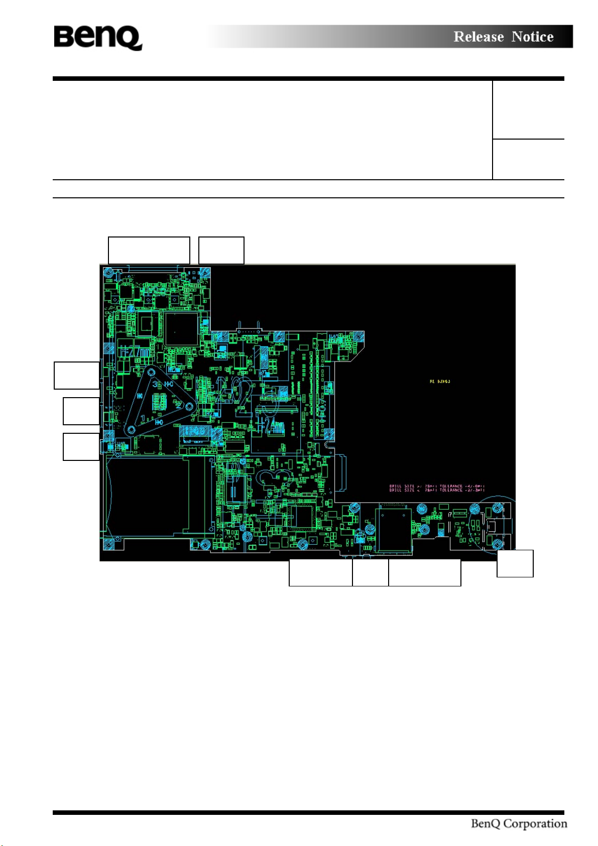
The picture shows the Joybook DHS52 I/O ports and main board architecture
Form No: BQY0-0B-003-32(031205)
4
Page 5
Product System (PS)
Subject:
Doc. No.
Project Code:
Model Name:
C2-201 Product Internal Engineering
Spec.
99.K4501.001
DHS5
Part No.:
Component Part.
No.:
Port replicator
DC in
USB*
RJ4
139
99.K4501.000
99.K4501.000-C2-201-001
NA
Rev.: 0
Page 5 of 28
Form No: BQY0-0B-003-32(031205)
MICPhone Jack
Card reader
RJ11
5
Page 6

Product System (PS)
Subject:
Doc. No.
Project Code:
Model Name:
C2-201 Product Internal Engineering
Spec.
99.K4501.001
DHS5
Part No.:
Component Part.
No.:
99.K4501.000
99.K4501.000-C2-201-001
NA
Rev.: 0
Page 6 of 28
CPU (Intel Pentium M Processor)
Functions Description Remark
Package Micro - FCPGA; 90nm
Features * On die 32KB instruction cache
* On die 32KB write-back data cache
* On die L2 2MB cache
* Advanced GTL+ bus driver technology
* Support streaming SIMD extensions 2(SSEE2)
* Dynamic power down of data bus buffers
* Support host bus dynamic bus inversion(DINV)
1.6GHz, 1.73GHz,
1.56GHz, 2.0GHz,
2.13GHz
Voltage Core = 1.34V to 0.94V
VCCA = 1.8V
VCCP = 1.05V
North Bridge (Alviso - Intel 915GM)
Functions Description Remark
Package Micro – FCBGA 37.5mm X 40mm
Voltage * VCC = 1.05 V (Core power)
* VCCADAC = 1.5 V (DAC Power)
* VCCDVO = 1.5 V (DVO power)
* VCCDLVDS = 1.5 V (LVDS Power)
* VCCGPIO = 1.5 V (GPIO Power)
* VCCHL= 1.5V (Hub Interface Power)
* VCCQSM= 2.5V (System Memory Clock power)
* VCCSM= 2.5V (Memory IO Power)
* VCCTXLVDS= 2.5V (LVDS Data/Clk TX Power)
Features * support processor host bus at 400/533Mhz
* support 32-bit AGTL+ host bus addressing
* support up to two DDR/DDR2 channels (64-bits)
* support 128MB(Min.)/2GB(Max.)
* support DDR 333 and DDR2 400/533 devices
* Integrated one x16 PCI Express Interface
* Support traditional PCI/AGP style traffic
South Bridge (ICH4-M - Intel 82801DBM)
Functions Description Remark
6
Form No: BQY0-0B-003-32(031205)
Page 7

Product System (PS)
Subject:
Doc. No.
Project Code:
Model Name:
C2-201 Product Internal Engineering
Spec.
99.K4501.001
DHS5
Part No.:
Component Part.
No.:
Package BGA 31mm X 31mm
Voltage * Main logic voltage = 1.5V
* VCCSUS1_5 = 1.5V (resume logic voltage)
* VCCLAN1_5 = 1.5V (LAN logic voltage)
* VCC3_3 = 3.3 V (main I/O)
* VCCSUS3_3 = 3.3 V (resume I/O voltage)
* VCCLAN3_3 =3.3 V (LAN I/O voltage)
* V5REF = 5 V
* V5REF_SUS = 5V
* VCCRTC = 3.3 V
* VCCHI = 1.5 V
* VCCP = 1.05 V
Features * PCI one x4 Express Interface
* PCI 2.3 (7PCI bus masters supported)
* Serial ATA(SATA) Controller (two port)
* Bus Master IDE (PATA) Controller (two devices)
* USB 1.1 and 2.0 host controllers
* LAN controller via LAN connect interface
* System management bus (SMBus) 2.0 controller
* AC 97 2.3/Azalia link controller (up to 6channels)
* LPC / FWH interface
* Advance programmable interrupt controller (APIC)
support
* Build in Real time clock (RTC)
* IRQ Controller
99.K4501.000
99.K4501.000-C2-201-001
NA
Rev.: 0
Page 7 of 28
Clock Generator (ICS ICS954206)
Functions Description Remark
Package 56-pin TSSOP
Frequency *100Mhz~400Mhz for CPU and North Bridge
*100Mhz for North Bridge, South Bridge, SATA, all of
PCI Express Devices
*96Mhz for DOT
*48Mhz for ICH6 USB, 4in1 card reader of PCI7411
*33Mhz for all of PCI devices
*14.318Mhz for South Bridge, Audio AC97,Super I/O
Features *Support spread spectrum modulation, down spread 0
to –0.5%. (CPU, 3V66, PCI)
7
Form No: BQY0-0B-003-32(031205)
Page 8

Product System (PS)
Subject:
Doc. No.
Project Code:
Model Name:
C2-201 Product Internal Engineering
Spec.
99.K4501.001
DHS5
Part No.:
Component Part.
No.:
99.K4501.000
99.K4501.000-C2-201-001
NA
Rev.: 0
Page 8 of 28
*Efficient power management scheme through PD#,
CPU_STOP# and PCI_STOP#
System Memory
DHS52 supports DDR333 SDRAM two 200 pin SO-DIMM socket for expansion with 128MB,
256MB, 512MB, 1GB DDR SDRAM Module. It can achieve total 128MB/2GB system memory.
VGA shares memory with system memory. Minimum from 8MB and maximum up to 64MB
Display Subsystem ( QDI QD13WL01)
DHS52 supports QDI QD13WL01 13” wide color TFT LCD. The screen format is intended to
support the WXGA [1280(H)x768(V)] screen and 262k colors (RGB 6-bits data driver). All input
signals are LVDS interface compatible.
Brightness Requirement:
Min. 30 nits
Max. Depend on LCD 150~200 nits
Default: Max.
Auto Dim: -1 step
CardBus/IEEE-1394/Media card reader controller (TI PCI7411)
Functions Description Remark
Package 288-terminal MicroStar BGA
Voltage Powered at 1.8V/2.5V for core logic, and 3.3V for other
Features
*PCI bus, bus master support.
*Support serial IRQ interrupt.
*Support the four widely used small form factor flash
media formats.
*Physical and Link Function
*Implements PCI Burst Transfers and Deep FIFOs to
Tolerate Large Host Latency
*Supports Serial Bus Data Rates of 100, 200 and 400
Mbits/second
8
Form No: BQY0-0B-003-32(031205)
Page 9
Product System (PS)
Subject:
Doc. No.
Project Code:
Model Name:
C2-201 Product Internal Engineering
Spec.
99.K4501.001
DHS5
Part No.:
Component Part.
No.:
99.K4501.000
99.K4501.000-C2-201-001
NA
Rev.: 0
Page 9 of 28
PC card power controller chip (TI TPS2220)
Functions Description Remark
Package SSOP-24 pin package
Voltage 3.3V, 5.0V, 12V
Features Support 3V, 5V, 12V to PCMCIA socket
LAN (Reltec RTL8100CL)
Functions Description Remark
Package 128 pins LQFP
Power 2.5V, 3.3V
Features 10/100Mbps Ethernet
RJ45 LED indicator • Green On: When plug Ethernet cable into this LAN
module.
• Green Off: When take off Ethernet cable from this
LAN module.
• Green Blinking: When data TX/RX data transfer to
other one Ethernet module.
• Orange On: When working on 100M speed.
• Orange Off: When working on 10M speed.
Bluetooth (Wistron 92035 USB)
Functions Description Remark
Package Mini USB Embedded Blue tooth module
Frequency range 2.402– 2.480 GHz
Power 3.3V
Features
*Blue tooth 1.1 qualified Embedded USB Module
*Upgradeable to Blue tooth 1.2 when SIG specification is
ratified
*Extremely small size (26mm X 14mm)
*Class 2 specification RF output power (max +4 dBm)
*Full Blue tooth data rate (723 kb/s)
*USB 2.0 compliant interface
*LED indicator built-in Label
Form No: BQY0-0B-003-32(031205)
9
Page 10

Product System (PS)
Subject:
Doc. No.
Project Code:
Model Name:
C2-201 Product Internal Engineering
Spec.
99.K4501.001
DHS5
Part No.:
Component Part.
No.:
99.K4501.000
99.K4501.000-C2-201-001
NA
Rev.: 0
Page 10 of 28
Modem (Conexant Standard MDC modem module)
Functions Description Remark
Package 28 pins QFN on board
Power 3.3V
Features *Support V.92/V.90 analog receive data up to 56kbps
with V.44 data compression
*Fax modem with send and receive rate up to 14.4kbps
*Data compression and error correction
*telephony / Voice / TAM Data / Fax / Voice call
discrimination
*Worldwide operation including U.S / Japan / Canada
Power Controller and Keyboard controller (NS PC97551)
Functions Description Remark
Package 176 pins TQFP
Power 3.3V operation with 5V tolerant buffers
Features
*16-bit embedded RISC processor
*Host bus interface (KBC, PM)
*PS/2 interface
*Hold function
*Shared BIOS memory
*Fully ACPI compliant
Super I/O controller (SMSC LPC47N217)
Functions Description Remark
Package 64 pins TQFP
Power 3.3V operation with 5V tolerant buffers
Features
*LPC bus interface:
Form No: BQY0-0B-003-32(031205)
10
Page 11

Product System (PS)
Subject:
Doc. No.
Project Code:
Model Name:
C2-201 Product Internal Engineering
Spec.
99.K4501.001
DHS5
Part No.:
Component Part.
No.:
Synchronous cycles, up to 33Mhz bus clock
8-bits I/O cycles
Up to four 8-bits DMA channels
*PC2001 and ACPI Compliant:
PnP configuration register structure
15 IRQ routing options
*Parallel interface support:
An Enhanced Parallel Port (EPP) compatible with EPP
1.9 also supports version EPP1.7 of the Xircom
specification
99.K4501.000
99.K4501.000-C2-201-001
NA
Rev.: 0
Page 11 of 28
An Extended Capabilities port (ECP)that is IEEE 1284
compliant .
*UART serial port interface:
High speed UART with send/receive 16 byte FIFOs.
Support data rate up to 1.5M baud
*Fast Infrared support:
IrDA 1.1 compliant, HP-SIR, ASK-IR, Consumer IR
Support
BIOS ROM (SST SST39VF080)
One 40-pins SSOP package 8Mbits FLASH ROM SST39VF080 is used for BIOS, keyboard
encoder and power controller codes. It occupies system memory area E0000-FFFFF. After posting
system, the shadow RAM function will be enabled.
Functions Description Remark
Package SSOP 40-Lead
Voltage 3.3V
Features *1024KX8 CMOS Boot Block Flash Memory
*256 bytes per block
*Supply current Icc =30mA (Max)
Iccsb=5uA (Max)
Form No: BQY0-0B-003-32(031205)
11
Page 12

Product System (PS)
Subject:
Doc. No.
Project Code:
Model Name:
C2-201 Product Internal Engineering
Spec.
99.K4501.001
DHS5
Part No.:
Component Part.
No.:
99.K4501.000
99.K4501.000-C2-201-001
NA
Rev.: 0
Page 12 of 28
Audio CODEC (Conexant CX20551)
Functions Description Remark
Package 48 pin TQFP
Voltage 3.3V digital and 5V analog
Features *AC ‘97 Revision 2.3-compliant audio/modem codec
using SmartDAA technolog
*3.3 V analog and I/O operation; uses Vaux for power
management modes
*Sony Philips Digital Interface (S/PDIF) output
*Meets performance requirements for audio on PC2001
systems
*Choice of 3 DAC channels for 2.1 audio configuration
support or 6 DAC channels for 5.1 audio configuration
support
*One ADC supports stereo microphone recording
*Supports audio formats ranging from 16-bit, 48 kHz to
24-bit, 192 kHz
Audio Amplifier (Maxim 9755ETI+)
Functions Description Remark
Package 24-Pins Thin-QFN
Voltage 2V~5.5V
Features
*PC2001 Compliant
*High 90 dB PSRR
*Selectable Gain settings
*Thermal shutdown protection circuitry
Power Output 2.6 W(typical) for stereo BTL Speaker amplifiers
Speaker (YUNGTECH 2514CP-5)
Functions Description Remark
12
Form No: BQY0-0B-003-32(031205)
Page 13

Product System (PS)
Subject:
Doc. No.
Project Code:
Model Name:
C2-201 Product Internal Engineering
Spec.
99.K4501.001
DHS5
Dimension
25.0*14.0*6.0 mm
Part No.:
Component Part.
No.:
99.K4501.000
99.K4501.000-C2-201-001
NA
Magnet Materials Rare Earth, Size,Φ7.5 ×1.0mm
Impedance 4Ω ±15% at 1000Hz
Frequency Range 550Hz ~ 18 KHz Average SPL –10dB
Lowest resonant frequency 600 Hz + 20%
Power Rating Normal 1500mW; Maximum 2000mW
Output sound pressure level
78 ± 3dB /1.0 Watt.1Meter
(S.P.L)
Thermal Sensor (Maxim 6657)
Rev.: 0
Page 13 of 28
Functions Description Remark
Part name Maxim 6657
Package SOIC 8 pins
Interface SMBus / I2C bus
Function Thermal sensor with over
temperature indication
AC Adapter:
Delta SADP-65KB BFB
Lite-On PA-1650-02BQ
65W or above universal AC adapter 90-264V AC, 47-63HZ
3-wire power cord and DC output cable
L connector to system box
Over-voltage protection: Trip point 24V (max.) shutdown.
Over-current protection: Output shorted without damage
Wire from adaptor to system should be at least 1.6m; from AC to adaptor at least 1.6m
Input characteristics:
Functions Description
Input voltage 100 ~ 240V AC
Input frequency range 50 ~ 60 Hz
Maximum input AC
1.6A
current
Inrush current 50A@115VAC
100A@230VAC
Form No: BQY0-0B-003-32(031205)
13
Page 14

Product System (PS)
Subject:
Doc. No.
Project Code:
Model Name:
C2-201 Product Internal Engineering
Spec.
99.K4501.001
DHS5
Part No.:
Component Part.
No.:
99.K4501.000
99.K4501.000-C2-201-001
NA
Efficiency 83% min. @115VAC input full load
Output characteristics:
Load range Regulation Ripple & Noise
Output Voltage
Minimum Maximum
+19V 0A 3.42A +-5% 400mVp-p
RTC battery:
Specification : Maxell ML1220 Rechargeable LiIon battery
Normal capacity 14 mAhr
Normal voltage 3.0 V
Rev.: 0
Page 14 of 28
3.2 SW requirement
(The detail description should refer to SW spec. directly and this one should forcus on the SW
marketing spec. for example, OS edition/Language, boundled AP,LED/Hot-key definition,
specification ….. etc.)
Target Operating Systems
BenQ will offer support for the following operating systems:
Require Windows XP (Home Edition)
Require Windows XP (Professional Edition)
System Management BIOS (SMBIOS)
DHS52 BIOS must support the SMBIOS BIOS Specification version 2.3 (formerly DMI
BIOS). Customer requires only the subset of SMBIOS functions and structures that are
listed as required in the SMBIOS specification, and as required by the PC2001
specification.
SMBIOS specification.
Note SMBIOS in DHS52 must provide 32-bit entry table in F000 Segment to be PC99+
compliant, also this is the preferred method, since Plug and Play interface will eventually go
away and new OS do not handle 16-bit interfaces well.
Form No: BQY0-0B-003-32(031205)
14
Page 15

Product System (PS)
Subject:
Doc. No.
Project Code:
Model Name:
C2-201 Product Internal Engineering
Spec.
99.K4501.001
DHS5
Part No.:
Component Part.
No.:
Type 0: BIOS Information
Field
BIOS Version
The BIOS version is defined in the “BIOS Version Numbers” section of
this document
Type 1: System Information SMBIOS
Field
Manufacturer BenQ
99.K4501.000
99.K4501.000-C2-201-001
NA
Rev.: 0
Page 15 of 28
Product Name Joybook S52
Version TBD
Serial Number 24 bytes
UUID 16 bytes
2.2.3 SMBIOS Retail Market System Information
Type 2: Base Board Information SMBIOS
Field
Manufacturer BENQ
Product Name
Joybook DHS52
Version
Serial Number N/A
Security
Security features protect the data of machine from unveiled publicly and unauthorized
access. BenQ will provide the security features outlined in this section.
BenQ provides a two-level password security scheme stored in a non-volatile storage device
(EEPROM).
Supervisor password.
User Password.
The password, if set, is required to gain access to the Setup utility, and to boot the system.
The difference between the two password levels only exists when executing the Setup utility.
Form No: BQY0-0B-003-32(031205)
15
Page 16

Product System (PS)
Subject:
Doc. No.
Project Code:
Model Name:
C2-201 Product Internal Engineering
Spec.
99.K4501.001
DHS5
Part No.:
Component Part.
No.:
Using the administration password to enter the Setup utility allows the user to access all the
configurable fields. Whereas using the user password only allows the user
to configure a limited number of fields.
DHS52also provides a H/W solution to reset or bypass password.
Secured data is kept in a non-volatile storage device (EEPROM). The entire data structure of
secured data in the non-volatile storage must be verified with a checksum calculation.
Others follow Third party BIOS’s Security specification.
Serial Number (S/N)
T The Serial Number string will be stored in the secured data area. The S/N will not be
displayed in BIOS SETUP menu. The S/N is an alphanumeric string of 24 bytes in length.
The rule of S/N is: P/N (10 bytes) + Year (1 bytes) + Week (2 bytes) + series No (5 bytes) +
model (6 bytes). The following is an example of the string representation of S/N:
99K0502T0131500001DHS52.
Model ID String (for SLP)
On BenQ System has a specific text string embedded in BIOS ROM F000:FFB0h. It will be
identified the model and BIOS version by diagnostic program and flash utility. The format
is as below:
B0 B1 B2 B3 B4 B5 B6 B7 B8 B9 BA BB BC BD BE BF
B e n Q H u b
99.K4501.000
99.K4501.000-C2-201-001
NA
Rev.: 0
Page 16 of 28
System Meter
DHS52 should provide 3 bytes in CMOS and the default value is 0. It will auto count the
hour of usage when boot to OS. The format is Hour(2 bytes): Min(1 byte)
System cannot reset its value.
Debugging
Basic unit problem analysis will be provided through the use of POST and runtime
checkpoint codes output to I/O port 378h.
Auto Dim
The system will support an automatic dimming of the LCD backlight when the AC power
source is NOT available (running on battery power).
The user may always manually increase or decrease the brightness, including to full
maximum setting.
The current user setting of brightness (along with current power source) will be saved, and
the brightness setting will be restored to the user’s set level at the next boot or resume.
Form No: BQY0-0B-003-32(031205)
16
Page 17

Product System (PS)
Subject:
Doc. No.
Project Code:
Model Name:
C2-201 Product Internal Engineering
Spec.
99.K4501.001
DHS5
Part No.:
Component Part.
No.:
99.K4501.000
99.K4501.000-C2-201-001
NA
Under Ac mode, if user plugs out AC, it will decrease one step automatic. After user plugs
in the AC, it will increase one step. There are two special cases that KBC should take care.
DC mode and set maximum of brightness
Don’t change the brightness level when AC in. It shouldn’t decrease when user plugs AC
out.
AC mode and set the minimum of brightness
Don’t change the brightness when AC out. It shouldn’t increase one step when user plugs
AC in again.
Boot Block
DHS52 BIOS provided Crisis mode to support Boot Block function provides a safe
solution to recover system BIOS in case of BIOS code in flash memory is corrupted. There
are two ways to enter Crisis Mode:
BIOS corrupted, Boot Block function will enter Crisis mode automatically
Plug Bootblock board into print port to force Boot Block function to enter Crisis mode.
POST
POST Logo
The logo should be displayed on the screen during POST. It is a colored bitmap
(800*600*256 color) and the background should be black. When there is an error
occurred, BIOS closes the logo and switches to text mode to display the error message.
BIOS support ESC key for Popup Boot Menu during POST.
POST Error
If the CMOS checksum is bad, the BIOS should load the default values.
Fast POST
BenQ will comply with the Microsoft Simple Boot Flag Specification v1.0/v2.0. In that
document, two types of boot sequences are defined.
Boot Device Sequence
BIOS will provide the user with the ability to select the devices for attempting to boot an OS.
The user will be able to specify which system device will be attempted 1st, 2nd, and so on.
During Post, user can also use the “ESC” to select the boot device, and user press the “F10”
to enter recovery partition and run recovery program.
The list of possible boot devices sequence will include:
USB Floppy
Primary Hard Drive (built-in)
CD-ROM Drive
Network (PXE) for built-in LAN
Rev.: 0
Page 17 of 28
Form No: BQY0-0B-003-32(031205)
17
Page 18

Product System (PS)
Subject:
C2-201 Product Internal Engineering
Part No.:
99.K4501.000
Rev.: 0
Spec.
Doc. No.
Project Code:
Model Name:
99.K4501.001
DHS5
Component Part.
No.:
99.K4501.000-C2-201-001
NA
Page 18 of 28
Boot From LAN
The systems of BenQ has the internal LAN card, booting the system from the network
could be done by:
Specify the network as the first boot device.
At post, user could change the system boot from network. It depends on Third party
BIOS’s design.
SVID and SSID of PCI device
BIOS should program the Subsystem Vendor ID and Subsystem ID into the PCI
configuration space for each PCI device. The Subsystem Vendor ID will be 17ffh for all
devices. The Subsystem ID will be 058bh.
Keyboard Hot Keys
A Message(BenQ Hotkey Manager) will be show when the hot key is activated (as noted in
the below table), to indicate to the user that the selected action has been performed.
Form No: BQY0-0B-003-32(031205)
18
Page 19

Product System (PS)
Subject:
Doc. No.
Project Code:
Model Name:
C2-201 Product Internal Engineering
Spec.
99.K4501.001
DHS5
Part No.:
Component Part.
No.:
99.K4501.000
99.K4501.000-C2-201-001
NA
Rev.: 0
Page 19 of 28
Table1. Hot Key
Definition
Function Hot Key
Function Hot Key
Hotkey Help Fn+F1
Sleep Fn+F2
LCD/CRT switch Fn+F3
Brightness Down Fn+F4
Brightness Up Fn+F5
TouchPad ON
TouchPad OFF
Speaker ON/OFF Fn+F7
Fn+F6
Volume Down Fn+F8
Volume Up Fn+F9
QPower switch Fn+F10
Bluetooth and Wireless on/off Fn+F12
-
In spite of those hot keys printed on keyboard, there are some special buttons in system of
BenQ. Following is the description.
Hotkey Function
IE (Internet/QMedia XS) E0 32/ E0 B2 E0 3A/ E0 F0
Email (E-mail) E0 6C/ E0 EC E0 48/ E0 F0 48
Form No: BQY0-0B-003-32(031205)
Make/Break
Ps2 Set1 Ps2 Set2
3A
19
Page 20

Product System (PS)
Subject:
Doc. No.
Project Code:
Model Name:
C2-201 Product Internal Engineering
Spec.
99.K4501.001
DHS5
Part No.:
Component Part.
No.:
Table2. Special Key Definition
There are 2 buttons for user easy to launch the Windows application. They will not support
user define.
Power-on Button
Power-on button on system, when Power-on button is press, system will enter Windows
environment or turn off windows when system is in windows mode.
Indicator at the upper side of keyboard
Following table is the descriptions of the detail behavior of the LED indicator at the upper
side of keyboard:
99.K4501.000
99.K4501.000-C2-201-001
NA
Rev.: 0
Page 20 of 28
Power On/Off/Standby
Color: Blue + Amber
Dual color LED
HDD access
Color: Blue Description: Flash when access
ODD access
Color: Blue Description: Flash when access
Num Lock
Color: Blue Description: On when enabled
Caps Lock
Color: Blue Description: On when enabled
Scroll Lock
Color: Blue Description: On when enabled
Indicator at the bottom edge
Battery Charging (turn off in S3/S4 DC only mode)
Color: Blue + Amber
Dual color LED
Description:
Blue LED on = System fully on
Amber LED on = System in Standby mode
Table5. LCD Indicator at the upper side of keyboard
Description:
Blue LED on = When battery is in use for
Form No: BQY0-0B-003-32(031205)
system on
Blue LED blinking = When in low battery
20
Page 21

Product System (PS)
Subject:
Doc. No.
Project Code:
Model Name:
C2-201 Product Internal Engineering
Spec.
99.K4501.001
DHS5
Part No.:
Component Part.
No.:
Amber LED on = When battery charging
Amber LED blinking = When battery is
abnormal
Both LED off = When battery is fully
charged
Memory Card reader access
Color: Blue Description: Flash when access
Kill switch RF LED (Wireless LAN/Bluetooth)
Color: Blue + Amber
Dual color LED
Description:
Blue LED on = Wireless LAN
99.K4501.000
99.K4501.000-C2-201-001
NA
Rev.: 0
Page 21 of 28
Power Management
Power management is controlled by an ACPI capable operating system.
ACPI Mode
In the ACPI system, ACPI OS take care all the Power states of the Device and system.
BenQ required power states:
Working (S0)
Standby (S3)
Hibernate (S4)
Soft Off (S5)
Definition of these states is provided in the Advanced Configuration and Power Interface
Specification, ACPI Ver1.0b or ACPI Ver 2.0 .
enable
Blue LED off = Wireless LAN disable
Amber LED on = Bluetooth enable
Amber LED off = Bluetooth disable
Table6. LCD Indicator at the bottom edge
1.1.1
Event
Form No: BQY0-0B-003-32(031205)
S3 S4/S5
Comments
21
Page 22

Product System (PS)
Subject:
Doc. No.
Project Code:
Model Name:
C2-201 Product Internal Engineering
Spec.
99.K4501.001
DHS5
Part No.:
Component Part.
No.:
RTC Alarm Yes Yes
Power on Button Yes Yes
Lid open Yes No
WOL Yes No
Onboard Modem Ring
Yes
No
99.K4501.000
99.K4501.000-C2-201-001
NA
Rev.: 0
Page 22 of 28
This Event is implemented via PME#
Support WOL under battery and
Adaptor
This Event is implemented via PME#
Support WOR under battery and
adaptor
PCMCIA Modem
No No
Ring
USB No No
Battery Critical Yes No This event should wake the system to
Full ON then notify the OS of the
Battery Critical event
TouchPad No No
Keyboard any key Yes No
Table7. ACPI Wake up Event
The following ACPI power management events will be recognized by the unit and the event
must be reported to the OS:
Battery Critical
Lid Open
Lid Close
Power Button
Sleep Button
AC/DC Change
Battery inserted/removed
Critical thermal threshold crossing (up or down)
Following event will let system enter either Standby or Hibernation mode, depend on other
setting:
Power Button (Either S3 or S4, depend on user’s setting)
Sleep Button (Either S3 or S4, depend on user’s setting)
Standby Timer
Form No: BQY0-0B-003-32(031205)
22
Page 23

Product System (PS)
Subject:
Doc. No.
Project Code:
Model Name:
C2-201 Product Internal Engineering
Spec.
99.K4501.001
DHS5
Part No.:
Component Part.
No.:
Hibernation Timer
Standby/Hibernation entry in Start / Shut down
Thermal Management
DHS52 BIOS will support ACPI Thermal management, the Thermal Zone and Cooling
control is defined as following table. Note the ACPI BIOS should support a thermal control
method as the following:
Object Description
_CRT Returns critical trip point in tenths Kelvin
_PSL List of pointers to passive cooling device objects
_PSV Returns Passive trip point in tenths Kelvin
_TC1 Thermal constant for Passive cooling
_TC2 Thermal constant for Passive cooling
_TMP Returns current temperature in tenths Kelvin
_TSP Thermal sampling period for Passive cooling in tenths of seconds
Table8. Thermal Control Methods
99.K4501.000
99.K4501.000-C2-201-001
NA
Rev.: 0
Page 23 of 28
The following table is recommended for ACPI thermal management:
FanControl -
temp raise temp fall
< 40 Fan off
48-> 55 46 -> 41 Low Speed 3.2V
56 -> 63 54 -> 47 Mid Speed 3.6V
Form No: BQY0-0B-003-32(031205)
23
Page 24

Product System (PS)
Subject:
Doc. No.
Project Code:
Model Name:
C2-201 Product Internal Engineering
Spec.
99.K4501.001
DHS5
Part No.:
Component Part.
No.:
> 64 High Speed 4.2V
< 74 Normal
> 74 Throttling by OS
> 95 OS shutdown
> 105 EC shutdown
> 110 Thermal shutdown
Table9. Thermal table
The CPU temperature over thermal threshold, EC will generate a thermal SCI and control
methods should take the right actions.
99.K4501.000
99.K4501.000-C2-201-001
NA
Rev.: 0
Page 24 of 28
Legacy Devices and Standards
Flash Update
The BIOS provide diskette-based BIOS update utility, include Boot Block with Crisis detect
and recovery. The BIOS update utility must be executed from the diskette. When booting to
the diskette, the BIOS update utility must automatically execute.
The BIOS update utility must contain an identification mechanism that will identify the
correct machine for which it is intended and execute only on that machine. The BIOS
update utility must not execute on any other machine.
The utility need to check model ID to decide to update BIOS or not.
The utility can run under Windows 2000 and Windows XP.
Additional BIOS Requirement
CMOS/ECMOS Map: The BIOS supply a document that contains definitions for all of the
CMOS/ECMOS addresses that are used by the BIOS. The BIOS also supply a list of
default values for the CMOS/ECMOS variables.
EEPROM programming tool
For use in service centers, UUID and MAC address programming tools should be provided.
3.3 ME requirement
(The detail decription should follow ME document and focus on the marketing spec.)
DHS52 should follow ME “BenQ appearance specification”,”BenQ accoustic test plan”
and “BenQ ME test plan” document
Form No: BQY0-0B-003-32(031205)
24
Page 25

Product System (PS)
Subject:
Doc. No.
Project Code:
Model Name:
C2-201 Product Internal Engineering
Spec.
99.K4501.001
DHS5
Part No.:
Component Part.
No.:
99.K4501.000
99.K4501.000-C2-201-001
NA
Dimension : 324(mm) x 227.6(mm) x24.9~34.6(mm)
Weight:2.25Kg
Acoustic Noise:
Please follow ME Acoustic noise test plan and spec.
Condition
Declared Sound Power Level
, bels
Average Sound Pressure Level
, dBA
Idle: Fan off and HDD spinning 3.5 28
Operation: Fan off and HDD
random seeks
Idle with Battery Charging: Fan
on and HDD spinning
3.8 31
3.9 32
Typical User Running Prime95
Software: Fan on and HDD
4.2 35
spinning
Operation: File copy from FDD
to HDD
4.7 40
Operation: CD-ROM perform
RANDOM ACCESS (average
time: 32 sec) operation and the
4.7 40
other storage equipment
standing by.
Operation: CD-ROM perform
RANDOM ACCESS (average
time: 32 sec) operation and the
4.7 40
other storage equipment
standing by.
Rev.: 0
Page 25 of 28
Form No: BQY0-0B-003-32(031205)
25
Page 26

Product System (PS)
Subject:
Doc. No.
Project Code:
Model Name:
C2-201 Product Internal Engineering
Spec.
99.K4501.001
DHS5
Part No.:
Component Part.
No.:
99.K4501.000
99.K4501.000-C2-201-001
NA
Rev.: 0
Page 26 of 28
4. Document & Change
When any of the above documents are revised the vendor will provide the detail update
documents to BENQ and BENQ will have the right to copy any of the above documents.
5. Acceptance Criteria
Any vendor supplying subsystem units should satisfy BENQ “
“
MIL-STD-105E
” requirement.
Joybook OQC Checklist”
& meet
6. Regulatory
EMC: CE,BSMI, C-Tick
Safety: CCC, CB, SASO
RF: DGT, SRRC, iDA_SIRIM, C_Tick, follow R & TTE
ESD (Basic spec. IEC61000-4-2):(Base on the supplier)
Air discharge
+/- 4KV: No error
+/- 8KV: No restart error and damage error
+/- 15KV: No damage error
Contact discharge
+/- 4KV: No error
+/- 6KV: No restart error and damage error
+/- 8KV: No damage error
7. Reliability, Maintainability & Quality
7.1 Relibility
MTBF meantime between failures (or meantime to failure)
Expected mean power-on time is 200 hours per month.
The subject products must have a minimum MTBF of 25,000 hours, for the
standard configuration.
7.2 Maintainability
Any faulty system, system element or system element subassembly should be replaceable.
Replacement of electronic components is not a field procedure, though it may be used at a
manufacturing plant or repair facility.
7.3 Quality
Form No: BQY0-0B-003-32(031205)
26
Page 27

Product System (PS)
Subject:
Doc. No.
Project Code:
Model Name:
C2-201 Product Internal Engineering
Spec.
99.K4501.001
DHS5
Part No.:
Component Part.
No.:
99.K4501.000
99.K4501.000-C2-201-001
NA
The product quality must meet the requirements of BenQ’s Joybook reliability test
requirements.
8. Environmental requirements
(Refer to the requirement of “BenQ ME Standard Test Plan and Procedure”)
9. Performance
Battery life
BatteryMark4.0.1 test :
6-cell Battery
Above 4 hrs (Dothan 1.73GHz)
3DMark2001SE test: (CPU Dothan 1.73GHz)
Above 3808score
3Dmark2003 test: (CPU Dothan 1.73GHz)
Above 863 score
Business winstone2004 test : (CPU Dothan 1.73GHz)
Above 22.3 score
MCC Winstone 2004 test : (CPU Dothan 1.73GHz)
Above 23.8 score
Rev.: 0
Page 27 of 28
10. Compatibility
The DHS52 must be compatible with the IBM PC/AT computer system. It must be able to
run MS-DOS6.22, Win ME and Win XP SP2. And Apply MS combined logo.
Form No: BQY0-0B-003-32(031205)
27
Page 28

Product System (PS)
Subject:
C2-201 Product Internal Engineering
Part No.:
Spec.
Doc. No.
Project Code:
Model Name:
99.K4501.001
DHS5
Component Part.
No.:
99.K4501.000
99.K4501.000-C2-201-001
NA
Rev.: 0
Page 28 of 28
Form No: BQY0-0B-003-32(031205)
28
 Loading...