

BenQ RP790 User Manual

RP790
Interactive Flat Panel
User Manual

Disclaimer
BenQ Corporation makes no representations or warranties, either expressed or implied,
with respect to the contents of this document. BenQ Corporation reserves the right to
revise this publication and to make changes from time to time in the contents thereof
without obligation to notify any person of such revision or changes.
Copyright
Copyright 2014 BenQ Corporation. All rights reserved. No part of this publication may be
reproduced, transmitted, transcribed, stored in a retrieval system or translated into any
language or computer language, in any form or by any means, electronic, mechanical,
magnetic, optical, chemical, manual or otherwise, without the prior written permission of
BenQ Corporation.

Table of Contents i
Table of Contents
Safety warnings and precautions ........................................1
Important safety instructions .............................................2
Notes on the LCD panel of this display ........................................2
Safety notice for remote control ...................................................3
Battery safety notice .........................................................................3
BenQ ecoFACTS ...............................................................................4
Package contents ...................................................................5
Setting up the display ............................................................6
Mounting the display .........................................................................6
Parts of the display and their functions .............................8
Front/Rear panel ...............................................................................8
Input/output terminals .................................................................. 9
Remote control ..............................................................................10
Using the remote control .............................................................12
Connection ..........................................................................13
Connecting audio/video signals ...................................................13
Connecting the touch module .....................................................17
Connecting power .........................................................................18
Using the touch screen ......................................................19
Important instructions for using the touch screen ..................23
Basic operations ..................................................................24
Turning the display on or off .........................................................24
Switching input signals ...................................................................25
Adjusting audio volume level........................................................ 25
The OSD (On-Screen Display) menu .............................26
OSD menu overview .....................................................................26
Operations in the OSD menu...................................................... 27
Picture menu .................................................................................28
Sound menu ..................................................................................29

Table of Contentsii
Product information ...........................................................36
Specifcations ...................................................................................
Dimensions ......................................................................................38
Supported input signal resolution ...............................................39
Troubleshooting ..................................................................40
36
Default menu .................................................................................30
Android system interface
...............................................
31
Main interface ..............................31
.....................................................................................31
.............................. ..............................
.....................................................................................
.....................................................................................32 .....................................................................................
EZWrite 2.0
.....................................................................................
33
Browser
ES File Explorer
.....................................................................................
33
WPS
.....................................................................................
33
Media player
.....................................................................................
34
All Apps
...........................................................
35
...........................................................
Settings
Safety warnings and precautions 1
Safety warnings and precautions
THIS EQUIPMENT MUST BE
GROUNDED
To ensure safe operation, the three-pin
plug must be inserted only into a
standard three-pin power outlet which
is effectively grounded through normal
household wiring. Extension cords
used with the equipment must have
three cores and be correctly wired to
provide connection to the ground.
Wrongly wired extension cords are a
major cause of fatalities.
The fact that the equipment operates
satisfactorily does not imply that the
power outlet is grounded or that the
installation is completely safe. For your
safety, if you are in any doubt about the
effective grounding of the power outlet,
please consult a qualifed electrician.
The lightning fash with arrowhead
symbol, within an equilateral triangle, is
intended to alert the user to the
presence of uninsulated "dangerous
voltage" within the product's enclosure
that may be of suffcient magnitude to
constitute a risk of electric shock to
persons.
The exclamation point within an
equilateral triangle is intended to alert
the user to the presence of important
operating and maintenance (servicing)
instructions in the literature
accompanying the appliance.
• The mains plug of the power supply cord shall remain readily operable. The AC
receptacle (mains socket outlet) shall be installed near the equipment and shall be easily
accessible. To completely disconnect this equipment from the AC mains, disconnect the
power cord plug from the AC receptacle.
• Do not place this display on an uneven, sloping or unstable surface (such as a trolley)
where it may fall and cause damage to itself or others.
• Do not place this display near water, like a spa or pool, or in a position which will allow
the splashing or spraying of water onto the display, like in front of an open window where
rain water may enter.
• Do not install this display in a confned space without proper ventilation and air
circulation, such as in a closed cabinet. Allow proper space around the display for
dissipating heat inside. Do not block any openings and vents on the display. Overheating
may result in hazards and electric shock.
• Installation of this display should only be performed by a qualifed technician. Failure to
install this display properly may cause injuries and damages to the personnels and the
display itself. Check the installation regularly and maintain the display periodically to
ensure the best working condition.
• Use only the accessories approved or recommended by the manufacturer to mount this
display. Using wrong or unsuitable accessories may cause the display to fall and result in
serious personal injuries. Make sure that the surface and fxing points are strong enough
to sustain the weight of the display.
• To reduce the risk of electric shock, do not remove covers. No user serviceable parts
inside. Refer servicing to qualifed service personnel.
• To prevent personal injuries, mounting the display or installing desktop stands is required
before use.

Important safety instructions2
Important safety instructions
1. Read these instructions.
2. Keep these instructions.
3. Heed all warnings.
4. Follow all instructions.
5. Do not use this apparatus near water.
6. Clean only with dry cloth.
7. Do not block any ventilation openings. Install in accordance with the manufacturer's
instructions.
8. Do not install near any heat sources such as radiators, heat registers, stoves, or other
apparatus (including amplifers) that produce heat.
9. Do not defeat the safety purpose of the polarized or grounding-type plug. A polarized
plug has two blades with one wider than the other. A grounding-type plug has two
blades and a third grounding prong. The wide blade or the third prong are provided for
your safety. If the provided plug does not ft into your outlet, consult an electrician for
replacement of the obsolete outlet.
10. Protect the power cord from being walked on or pinched particularly at plugs,
convenience receptacles, and the point where they exit from the apparatus.
11. Only use attachments/accessories specifed by the manufacturer.
12. Use only with the cart, stand, tripod, bracket, or table specifed by the
manufacturer, or sold with the apparatus. When a cart is used, use caution
when moving the cart/apparatus combination to avoid injury from tip-over.
14. Unplug this apparatus during lightning storms or when unused for long periods of
time.
15. Refer all servicing to qualifed service personnel. Servicing is required when the
apparatus has been damaged in any way, such as power-supply cord or plug is damaged,
liquid has been spilled or objects have fallen into the apparatus, the apparatus has been
exposed to rain or moisture, does not operate normally, or has been dropped.
Notes on the LCD panel of this display
• The Liquid Crystal Display (LCD) panel of this display has a very thin protective layer of
glass which is liable to marking or scratching, and cracking if struck or pressured. The
liquid crystal substrate is also liable to damage under excessive force or extreme
temperatures. Please handle with care.
• The response time and brightness of the LCD panel may vary with the ambient
temperature.
• Avoid placing the display in direct sun or where direct sun or spot lighting will shine onto
the LCD panel, as the heat may damage the panel and the external casing of the display,
and the bright light will make viewing the display more diffcult than necessary.
• The LCD panel consists of individual pixels to display images and is manufactured
according to the design specifcations. While 99.9% of these pixels work normally, 0.01%
of the pixels may remain constantly lit (in red, blue or green) or unlit. This is a technical
limitation of the LCD technology and is not a defect.

Important safety instructions 3
• LCD screens, like plasma (PDP) and conventional CRT (Cathode Ray Tube) screens, are
also susceptible to screen burn-in' or 'image retention' which can be found on the '
screen as visible fxed lines and shades. To avoid such damage to the screen, avoid
displaying still images (like On-Screen Display menus, IFP station logos, fxed/inactive text
or icons) for more than two hours. Change the aspect ratio from time to time. Fill the
entire screen with the image and eliminate the black bars whenever possible. Avoid
displaying images in 4:3 aspect ratio over a long period of time, otherwise there may be
visible burn marks on the screen as two vertical lines.
Note: Under certain circumstances, condensation may occur on the inner side of the
cover glass, it's a natural phenomenon and will not affect the operation of the display. This
condensation will usually disappear after around 2 hours of normal operation.
Safety notice for remote control
• Do not put the remote control in the direct heat, humidity, and avoid fre.
• Do not drop the remote control.
• Do not expose the remote control to water or moisture. Failure to do so could result in
malfunction.
• Confrm there is no object between the remote control and the remote sensor of the
product.
• When the remote control will not be used for an extended period, remove the batteries.
Battery safety notice
The use of the wrong type of batteries may cause chemical leaks or explosion. Please note
the following:
• Always ensure that the batteries are inserted with the positive and negative terminals in
the correct direction as shown in the battery compartment.
• Different types of batteries have different characteristics. Do not mix different types.
• Do not mix old and new batteries. Mixing old and new batteries will shorten battery life
or cause chemical leaks from the old batteries.
• When batteries fail to function, replace them immediately.
• Chemicals which leak from batteries may cause skin irritation. If any chemical matter
seeps out of the batteries, wipe it up immediately using a dry cloth, and replace the
batteries as soon as possible.
• Due to varying storage conditions, the battery life for the batteries included with your
product may be shortened. Replace them within 3 months or as soon as you can after
initial use.
• There may be local restrictions on the disposal or recycling of batteries. Consult your
local regulations or waste disposal provider.

Important safety instructions4
BenQ ecoFACTS
BenQ has been dedicated to the design and development of greener product as part of its
aspiration to realize the ideal of the "Bringing Enjoyment N Quality to Life" corporate '
vision with the ultimate goal to achieve a low-carbon society. Besides meeting
international regulatory requirement and standards pertaining to environmental
management, BenQ has spared no efforts in pushing our initiatives further to incorporate
life cycle design in the aspects of material selection, manufacturing, packaging,
transportation, using and disposal of the products. BenQ ecoFACTS label lists key ecofriendly design highlights of each product, hoping to ensure that consumers make
informed green choices at purchase. Check out BenQ's CSR Website at http://csr.BenQ.
com/ for more details on BenQ's environmental commitments and achievements.
Package contents 5
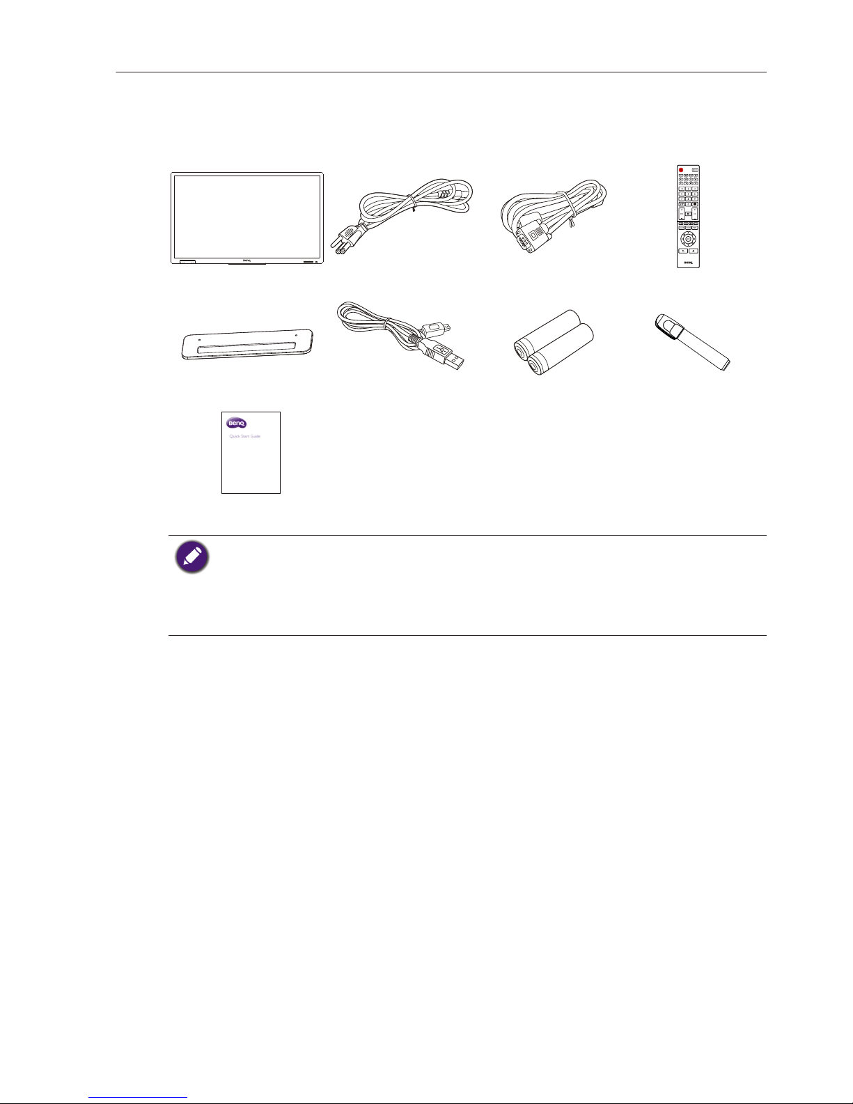
Package contents
Open the sales package and check the contents. If any item is missing or damaged, please
contact your dealer immediately.
LCD display Power cord x4
VGA (15-pin)
cable x1
Pen tray USB cable x1 AAA battery x 2 Touch pen x 2
Remote control
Quick start guide
• The type of power cord supplied may differ from that illustrated depending on your region of
purchase.
• Before discarding the package, check that you haven't left any accessories inside the box.
• Dispose of packaging materials wisely. You can recycle the cardboard carton. Consider storing the
package (if possible) for future transport of the display.
• Do not leave plastic bags within reach of young children or babies.

Setting up the display6
Setting up the display
Mounting the display
You can install the display on a vertical surface with a suitable wall mounting bracket or on
a horizontal surface with the optional desktop stands. Please pay attention to the following
notes during installation:
• This display should be installed by at least two adult persons. Attempting to install this
display by only one person may result in danger and injuries.
• Refer the installation to qualifed technicians. Improper installation may cause the display
to fall or malfunction.
Installing the display on a wall
1. Place a clean, dry and lint-free cloth on a fat, horizontal and object-free surface.
Make sure that the size of the cloth is larger than the display.
2. Gently lay the display on the cloth with the LCD screen facing down.
3. Remove the desktop stands from the display if installed.
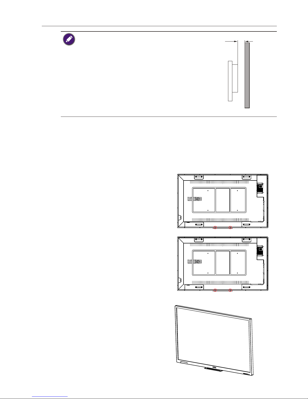
4. Identify the wall mounting screw
holes on the back of the display as
shown in the illustration.
*Screw type: M8
5. Install the wall mounting bracket
on the display and attach the
display to the wall according to
the mounting bracket’s
instructions. The length of the
screw should exceed the
thickness of the wall mounting
bracket by at least 10 mm. Make
sure that all screws are tightened
and secured properly.
(Recommended torque: 470 635N•cm). The mounting means
should be strong enough to bear
the weight of the display.
Thickness of
the wall
mounting
bracket
10 mm
(0.39")
LCD display
Setting up the display 7
• To maintain proper ventilation, keep at least 10 mm of clear
space from the back cover of the display to the wall.
• Please consult a professional technician for wall mount
installations. The manufacturer accepts no liability for
installations not performed by a professional technician.
Installing the pen tray
1. Place a clean, dry and lint-free cloth on a fat, horizontal and object-free surface.
Make sure that the size of the cloth is larger than the display.
2. Gently lay the display on the cloth with the LCD screen facing down.
3. Identify the wall mounting screw
holes on the back of the display
as shown in the illustration and
remove the 2 screws on the
display.
4. Place the pen tray on the back of
the display as shown, and fasten
the 2 screws back to the
respective holes.
5. Lay the display straight and the
pen tray is at the bottom edge of
the display.
Setting up the display8
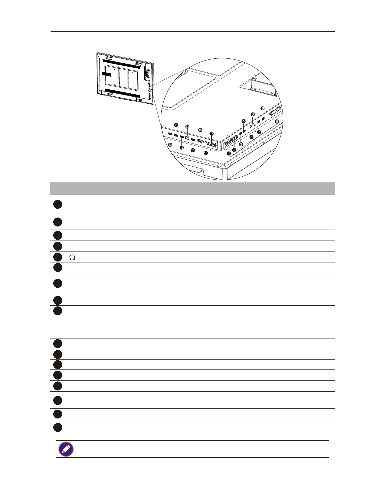
Parts of the display and their functions
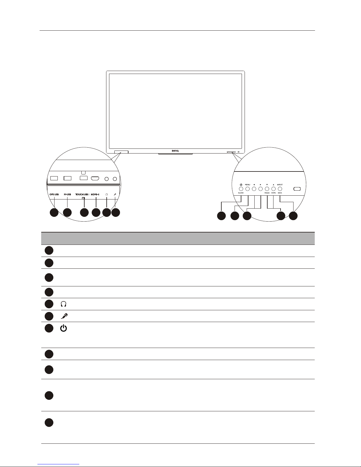
Front/Rear panel
No. Name Description
1
OPS USB
Connects to the OPS USB port from the front USB port .
2
M- USB
Accesses multimedia files on USB drives directly.
3
Connects to a microphone .
4
HDMI 1
Receives HDMI signals from an external device.
5
TOUCH USB 1
Connects the display and a computer by the USB cable to
6
Connects to a headsets.
7
8
9
MENU
Opens or closes the OSD menu or confirm input source.
10
• Freezes the screen.
• Scrolls through settings and options in the OSD menu.
• Ho m e / press to back to Main Screen in Android .
3/ 4
• Scrolls through settings and options in the OSD menu.
•34: Hot keys for audio volume adjustment.
1
2 3
4 5
6
7
8 9
10
11
ON/OFF/BLANK
Blank the display by pushing the button.
11
INPUT BACK/
Press this key to enter the menu to select the signal source or
5/6
FREEZE/HOME
•
Back / In Android system, returns to the previous screen.
•
activate the touch function .
Pushing the button longer(approximately 3 seconds) to turn
/
confirm the selection.
on or turn off the power.
•
•
Parts of the display and their functions 9
Input/output terminals
Connects the display and a computer by the USB cable to
activate the touch function .
No. Name Description
1
2
3
4
5
6
7
8
9
10
11
12
13
RS232(IN OUT)/
For external control
HDMI 5(4K/MHL)
Receives HDMI signals from an external device.
VGA
Receives analog RGB signals from an external device (such as a
computer).
AV IN(L/R)
Receives composite video signals from an external device (such as
a VCR or DVD player).
AV OUT(L/R)
Outputs composite video and audio signals from the AV IN input
to another display with a RCA connector.
M USB 2
Accesses multimedia files on USB drives directly.
COAXIAL
Connects to a coaxial cable to function efficiently as a radio frequency
TOUCH USB-2
OPS USB
Accesses use the USB drives directly in OPS.
HDMI 2
Receives HDMI signals from an external device.
HDMI 3
Receives HDMI signals from an external device.
HDMI OUT
Connects to display devices with a HDMI 3 input.
LAN
HDMI 4(4K)
Receives HDMI signals from an external device.
15
14
16
PC AUDIO
Receives audio signals from an external device.
17
YPbPr
Receives component video (YPbPr) signals from an external
device (such as a DVD player, HDTV device or Laser disc player).
LAN port 10/100M
Connects to a headsets.
transmission line.
RS232 IN: receives control signals from a computer or another display.
RS232 OUT: outputs control signals from the RS232 IN input to
another display.
•
TOUCH 1 must be used with HDMI 1,Touch 2 must be used with VGA , HDMI 2, HDMI3, HDMI 4,
HDMI 5 .
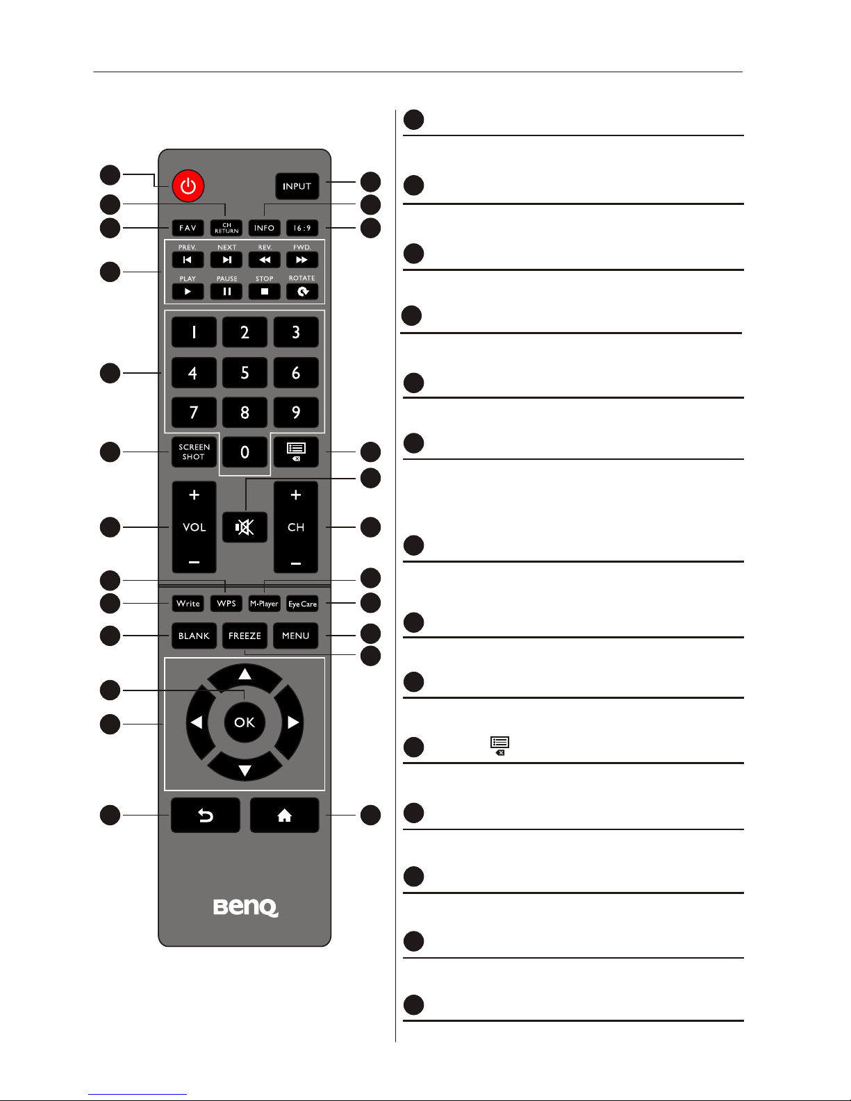
Parts of the display and their functions10
Remote control
Turns the display on or off.
1
POWER
Turn up/down the volume.
12
VOL- / VOL+
2
INPUT
Selects the input source.
4
INFO
Show the information of current input source .
8
Numeric buttons (0-9)
Press to enter numbers
13
CH+ / CH-
Change program channel.
Remote control
2
3
1
7
8
9
12
16
14
18
22
21
23
5 6
4
10
13
11
17
15
19
24
20
10
Delete a character / view program list.
CHLIST( )
11
MUTE
Turn on/off the sound.
U sed for operations of multimedia functions in smart
7
MULTI-MEDIA buttons
mode.
9
SCREEN SHOT
Capture the printed screen, and save to USB drive.
14
WPS
Open the WPS office app in android.
3
CH RETURN
TV Channel return.
5
FAV
Favorite TV program.
6
16:9
Change the display image to different mode under
non-Android system Mode: Full, 4:3, Film, Subtitle,
PC mode.
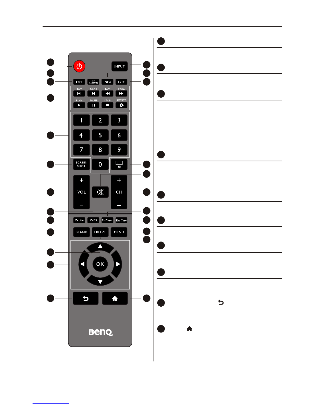
Parts of the display and their functions 11
Remote control
2
3
1
7
8
9
12
16
14
18
22
21
23
5 6
4
10
13
11
17
15
19
24
20
15
M-PLAYER
Open the Multimedia in android.
Freeze the screen.
20
FREEZE
21
OK
Confirm the selected options or save changes .
18
BLANK
Hides the image (the screen becomes blank) when
the OSD menu is off. Press again to resume normal
display.
10
MENU
19
Show the OSD menu.
24
HOME( )
Show the main screen in Android system.
23
Android Back key( )
Press this key to return to previous page.
16
WRITE
Open the EZWrite 2.0 app in android.
17
EYE CARE
Change the display mode to Classroom mode
NOTE: The users can keep pushing the"Eye Care"
bottom on the remote control and then the
classroom mode will be shown on the top-left
corner of the display, which is the low blue light
mode.
22
Scrolls through settings and options in the OSD
CURSOR KEYS( )
t/u/▲/▼
menu.
Parts of the display and their functions12
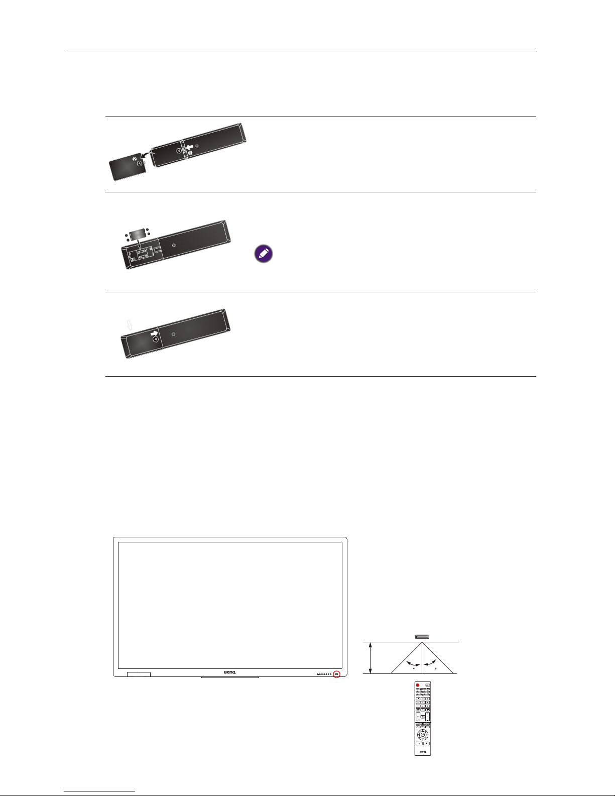
Using the remote control
Installing remote control batteries
1. Open the remote control battery compartment cover.
2. Insert the supplied batteries ensuring that the positive
and negative marked battery terminals match the (+)
and (-) marks in the battery compartment.
The supplied batteries are provided for your convenience so that
you can operate the display straight away. You should replace
them as soon as possible.
3. Refit the battery compartment cover.
Remote control usage tips
•
Point and aim the top front of the remote control directly at the display’s remote control
sensor window when you press the buttons.
• Do not let the remote control become wet or place it in humid environments (like
bathrooms).
• If the display’s remote control sensor window is exposed to direct sunlight or strong
light, the remote control may not operate properly. In this situation, change the light
source, readjust the angle of the display or operate the remote control from a location
closer to display’s remote control sensor window.
Max. 10 m
(32.8 feet)
+
-
-
+
+
-
-
+
30 30
13Connection
Connection
Connecting audio/video signals
Pay attention to the following notes when you connect cables:
• Please turn off all devices.
• Familiarize yourself with the audio/video ports on the display and the devices you want
to use. Be aware that incorrect connections may adversely affect picture quality.
• Do not remove cables from the ports by pulling the cable itself. Always grasp and pull the
connectors at the end of the cable.
• Ensure that all cables are fully inserted and frmly seated.
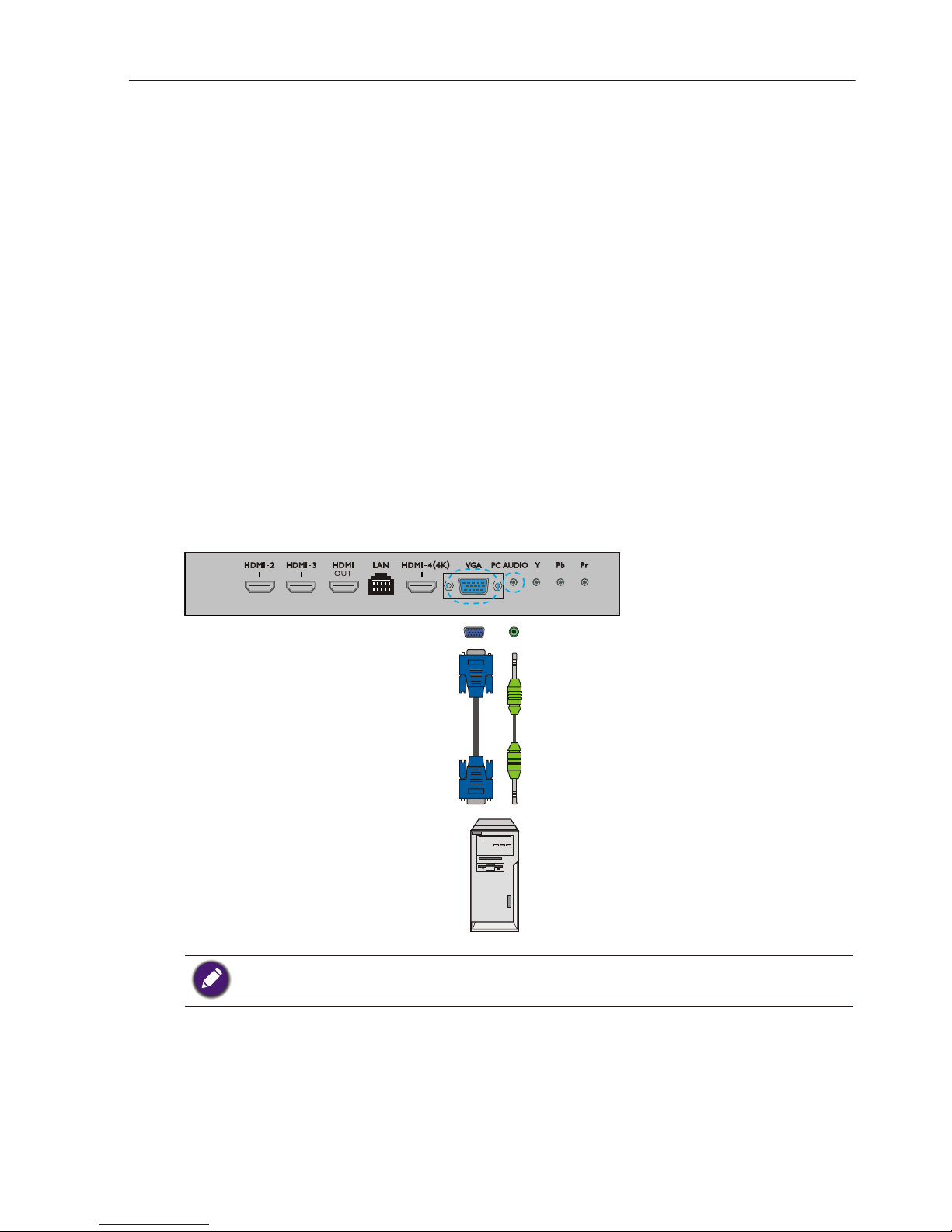
Connecting the VGA input
1. Connect the VGA jack on the display to the VGA output jack on a computer using a
D-Sub (15-pin) cable.
2. Connect the computer’s audio output jack to the AUDIO jack on the display using a
suitable audio cable.
3. To view images from this input, press the input button on the remote control and
VGA (15-pin) cable
Audio cable
Computer
The audio cable is not supplied and should be purchased separately.
select VGA .
Connection
14
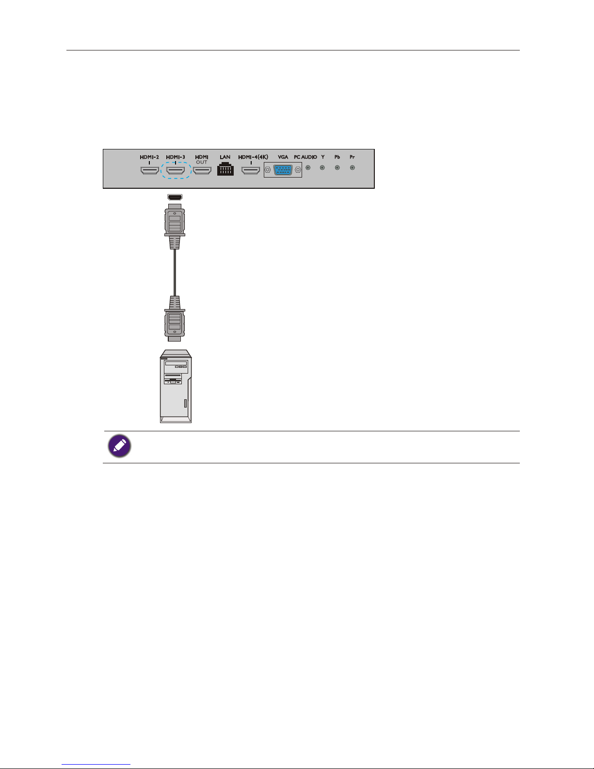
Connecting the digital inputs
1. Connect the HDMI output jack of a computer or A/V device (such as a VCR or DVD
player) to the HDMI 3 input jack on the display using an HDMI cable.
2. To view video image from this input, press the input button on the remote control
and select HDMI3.
Computer
HDMI cable
The cables are not supplied and should be purchased separately.

Connection 15
Connecting the YPbPr component video input
1. Connect the YPbPr jacks on the display to the component output jacks on an A/V
device (such as a VCR or DVD player) using a component video cable.
2. Connect the DVD player's audio output jacks to the L R jacks on the display using a
suitable audio cable.
3. To view video image from this input, press the input button on the remote control
and select YPbPr .
Audio
cable
DVD player / VCR
Component
video cable
The cables are not supplied and should be purchased separately.
Connection16
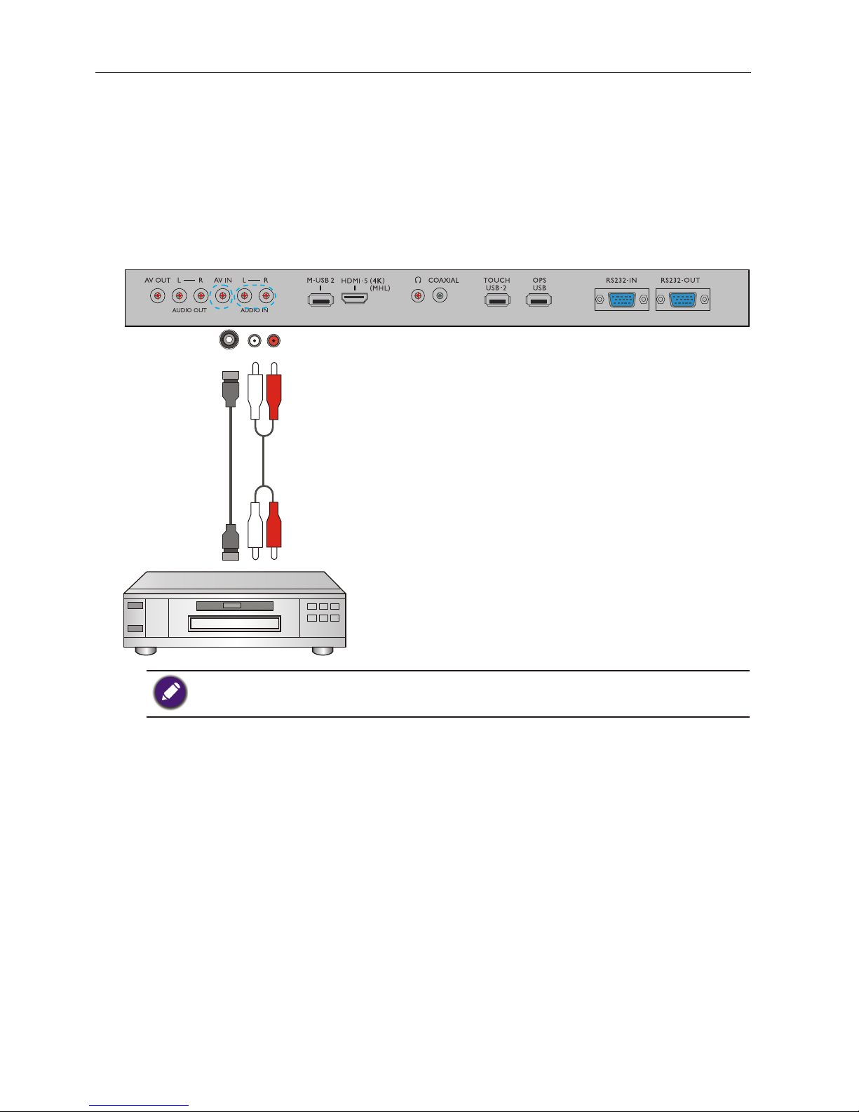
Connecting the AV inputs
1. Connect the AV on the display to the output jack on an A/V device (such as
a VCR) using an appropriate video cable.
2.
3. To view video image from this input,
press the input button on the remote control
and select AV.
Audio
cable
DVD player / VCR
AV
cable
The cables are not supplied and should be purchased separately.
Connect the VCR’s audio output jacks to the L R jacks on the display using a
suitable audio cable.
Connection 17
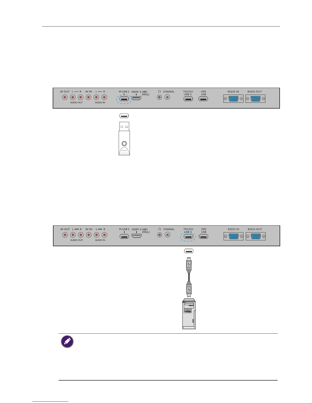
Connecting the multimedia inputs
To view multimedia files on the USB flash drive:
1. Plug the USB drive in the flash M USB port.
2.
USB driveflash
Connecting the touch module
Connect the USB TYPE A FOR TOUCH (type A) jack (TOUCH 1, TOUCH 2) on the
display to the USB port of a computer using the supplied USB cable.
The touch module of the display supports easy Plug-and-Play operation. There is no need
to install additional drivers on the computer.
USB cable
Computer
• Avoid blocking the touch screen frame (where sensors are located) when initiating the touch
module.
• It is highly recommended that you connect the display to the PC or laptop directly. Avoid
connecting the display to a face plate device which may cause failures in touch operations.
• If any ghost image occurs, please try to un-plug and then re-plug all USB cables. If the failure image
still exists, use another USB type A to A cable.
• TOUCH USB-1 must be used with HDMI 1 or TOUCH USB-2
must be used with
HDMI 2,
HDMI 3, HDMI 4, HDMI 5 or VGA.
When the users insert the USB flash drive, a notice will be popped up, which would
lead the users to the Multi-media mode. Please go to page 33 for more details.
Connection18
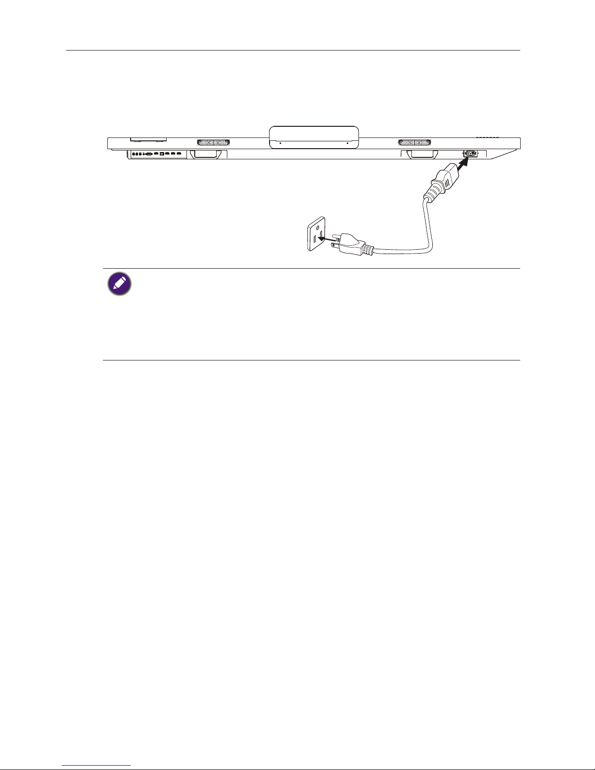
Connecting power
Plug one end of the power cord into the Power jack on the display and the other end into
an appropriate power outlet (if the outlet is switched, turn on the switch).
• The supplied power cord is suitable for use with 100-240V AC power only.
• The power cord and outlet illustrated may differ from the ones used in your region.
• Only use an appropriate power cord for your region. Never use a power cord which appears
damaged or frayed, or change the plug type on the power cord.
• Be aware of the power loading when you use extension cords or multiple outlet power boards.
• There are no user serviceable parts in this display. Never unscrew or remove any covers. There
are dangerous voltages inside the display. Turn off the power and unplug the power cord if you
intend to move the display.
Using the touch screen 19
Using the touch screen
You can use the optical touch screen to control your operating system. The touch screen
can emulate basic mouse functions and supports multi-touch functions for Windows 7/8*.
The following table shows a list of gestures you can use on the touch screen.
• Ensure that you have installed the USB cable on the display to a computer.
• *Multi-touch functions are only supported by Windows 8, Windows 7 - Home Premium,
Professional, Enterprise and Ultimate versions. For Windows XP, Windows Vista and Windows 7
- Starter and Home Basic versions, multi-touch is not supported.
• Windows is a registered trademark of Microsoft Corporation in the United States and other
countries.
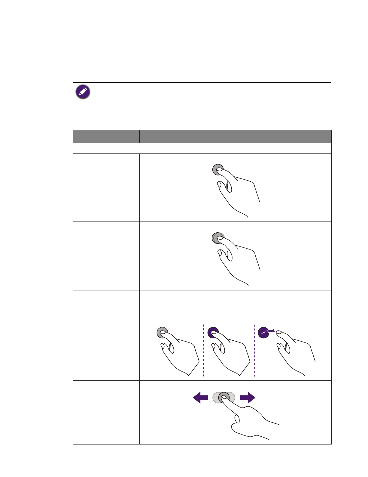
OS functions Gesture actions
For Windows XP, Windows Vista and Windows 7
Click
Tap the screen once.
Double-click
Tap the screen twice.
Right-click
1. Press on the target.
2. Hold and wait for a blue ring to appear.
3. Release your fnger.
Drag
Drag one fnger left or right.
Using the touch screen20
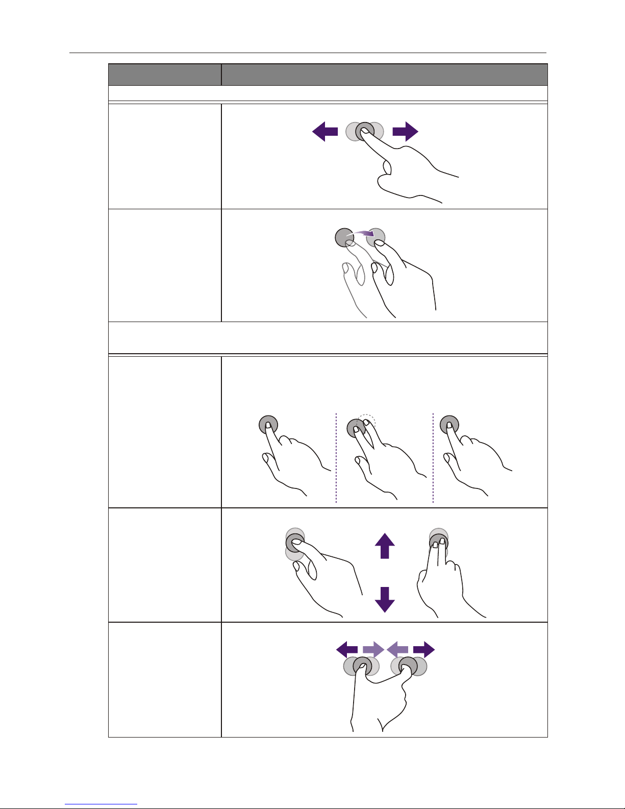
OS functions Gesture actions
For Windows Vista and Windows 7
Selection
Drag one fnger left or right.
Pan up / Pan down /
Back / Forward
Quickly drag your fnger (Flick) in a desired direction.
Multi-touch functions
For Windows 7 - Home Premium, Professional, Enterprise and Ultimate versions
Right-click
1. Press on the target.
2. Tap the screen with another fnger.
3. Release the second fnger.
Scrolling
Drag one or two fngers up or down .
Zoom
Move two fngers apart or toward each other.
or
 Loading...