

Page 1

Multiple Display Administrator
User Manual
Page 2

Disclaimer
BenQ Corporation makes no representations or warranties, either expressed or
implied, with respect to the contents of this document. BenQ Corporation reserves the
right to revise this publication and to make changes from time to time in the contents
thereof without obligation to notify any person of such revision or changes.
Copyright
Copyright 2016 BenQ Corporation. All rights reserved. No part of this publication may
be reproduced, transmitted, transcribed, stored in a retrieval system or translated into
any language or computer language, in any form or by any means, electronic, mechanical,
magnetic, optical, chemical, manual or otherwise, without the prior written permission
of BenQ Corporation.
Page 3

Table of Contents 3
Table of Contents
Disclaimer ..................................................................... 2
Copyright....................................................................... 2
Introduction .................................................................. 5
System requirements ..............................................................................5
Initial Setup ................................................................... 6
Installing Multiple Display Administrator............................................6
Connecting display(s) to the computer..............................................6
RJ-45 Ethernet connection...............................................................6
RS-232C connection.......................................................................... 7
Launching Multiple Display Administrator ......................................... 7
Overview of components and functions..................... 8
Toolbar.......................................................................................................8
Monitor list panel.....................................................................................9
Control panel............................................................................................ 9
Managing displays ....................................................... 10
Searching for displays............................................................................10
Serial (RS-232C) connection..........................................................10
Ethernet (LAN) connection ...........................................................11
Managing displays on the Monitor list panel....................................11
Tagging a display................................................................................11
Creating a group...............................................................................12
Deleting a group ...............................................................................12
Adding displays to an existing group............................................13
Deleting a display from a group ....................................................14
Deleting a display from the Monitor list panel ..........................14
Setting display ID automatically.....................................................14
Saving and loading display configutation files..............................14
Setting up display configurations .............................. 15
Information tab.......................................................................................15
Page 4

Table of Contents4
Control tab........................................................................................ 18
AV tab................................................................................................. 19
Schedule tab ...................................................................................... 20
Display Wall tab................................................................................ 21
Creating a display wall .................................................................... 21
Modifying display wall settings............................................................ 25
Alarm tab................................................................................................. 27
Additional operations................................................. 28
Changing login ID and password ....................................................... 28
Changing language ................................................................................. 28
Troubleshooting.......................................................... 29
Page 5
Introduction 5
Introduction
The Multiple Display Administrator is a software program that enables remote and
centralized management of a single or multiple BenQ digital signage displays on a host
computer. You can create and edit display groups, view status of displays as well as change
display settings. You can also tile multiple displays and create a video wall easily through a
step-by-step guided wizard.
The key features of the Multiple Display Administrator include:
• Automatic search for displays on the same Ethernet or RS-232C network
• Easy and intuitive management of displays and display groups
• Remote access to display settings and operations including power on/off and input
source selection
• Real-time monitoring of display status
• Step-by-step guided video wall setup
System requirements
To install and run Multiple Display Administrator, the computer must meet the following
minimum hardware and software requirements.
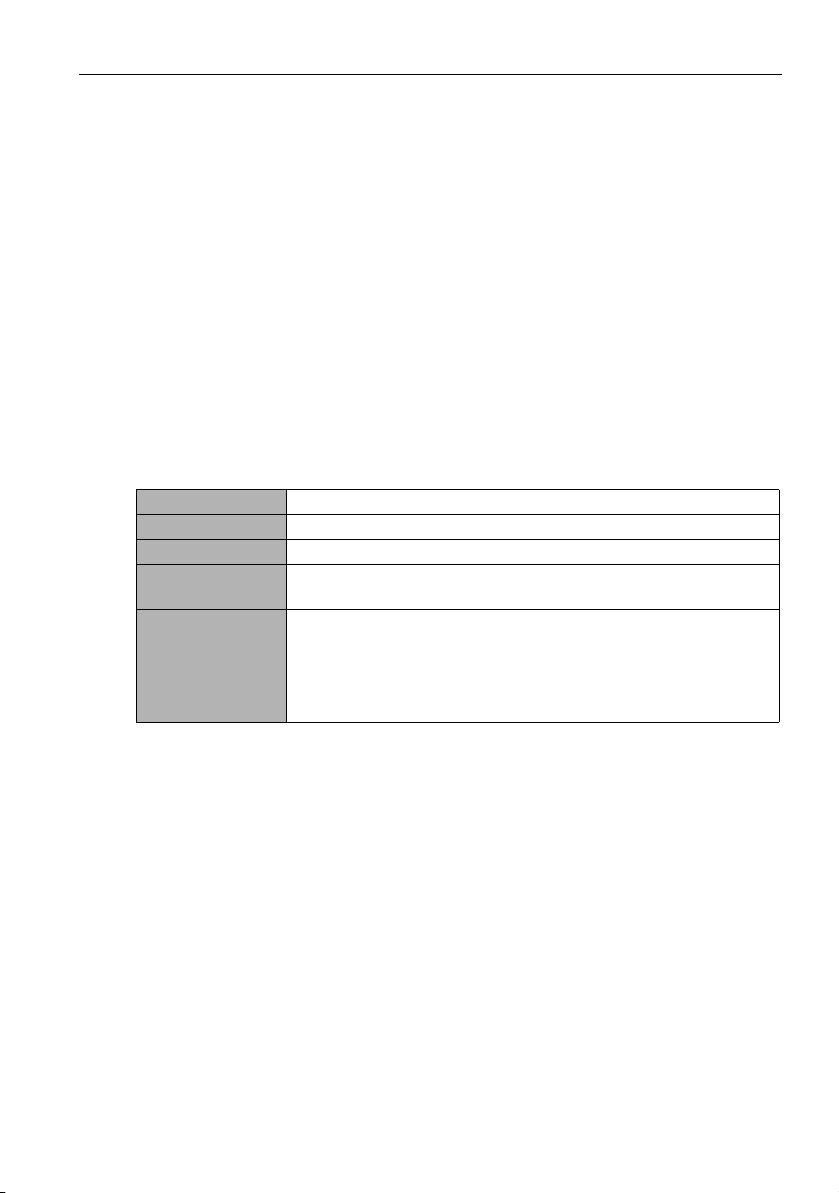
CPU Pentium/Athlon 1.8GHz
Free memory 512 MB
Hard disk space 100 MB
Connectivity An available Ethernet RJ-45 port (for Ethernet connection) or RS-
Operating
system
232C port (for RS-232C connection)
• Windows XP (32-bit)
• Windows Vista (32/64-bit)
• Windows 7 (32/64-bit)
• Windows 8
• Windows 10
Page 6
Initial Setup6
Computer
Hub, switch
or router
Display
RJ-45 cables
Initial Setup
The following operations must be performed before you can use the Multiple Display
Administrator to manage your display(s).
Installing Multiple Display Administrator
Ensure that the computer meets the minimum system requirements set forth on page 5.
1. Locate the setup.exe file and double-click it to begin installation.
2. Follow the on-screen instructions to complete the installation.
Connecting display(s) to the computer
The Multiple Display Administrator supports both Ethernet LAN and RS-232C daisy
chain connections to your display(s). You can choose one that best suits your display
deployment and network environment.
• For details on the location of ports and connectors, and instructions on the OSD settings,
please refer to the documentations of the computer and display.
• Do not make LAN and RS-232C connections at the same time.
RJ-45 Ethernet connection
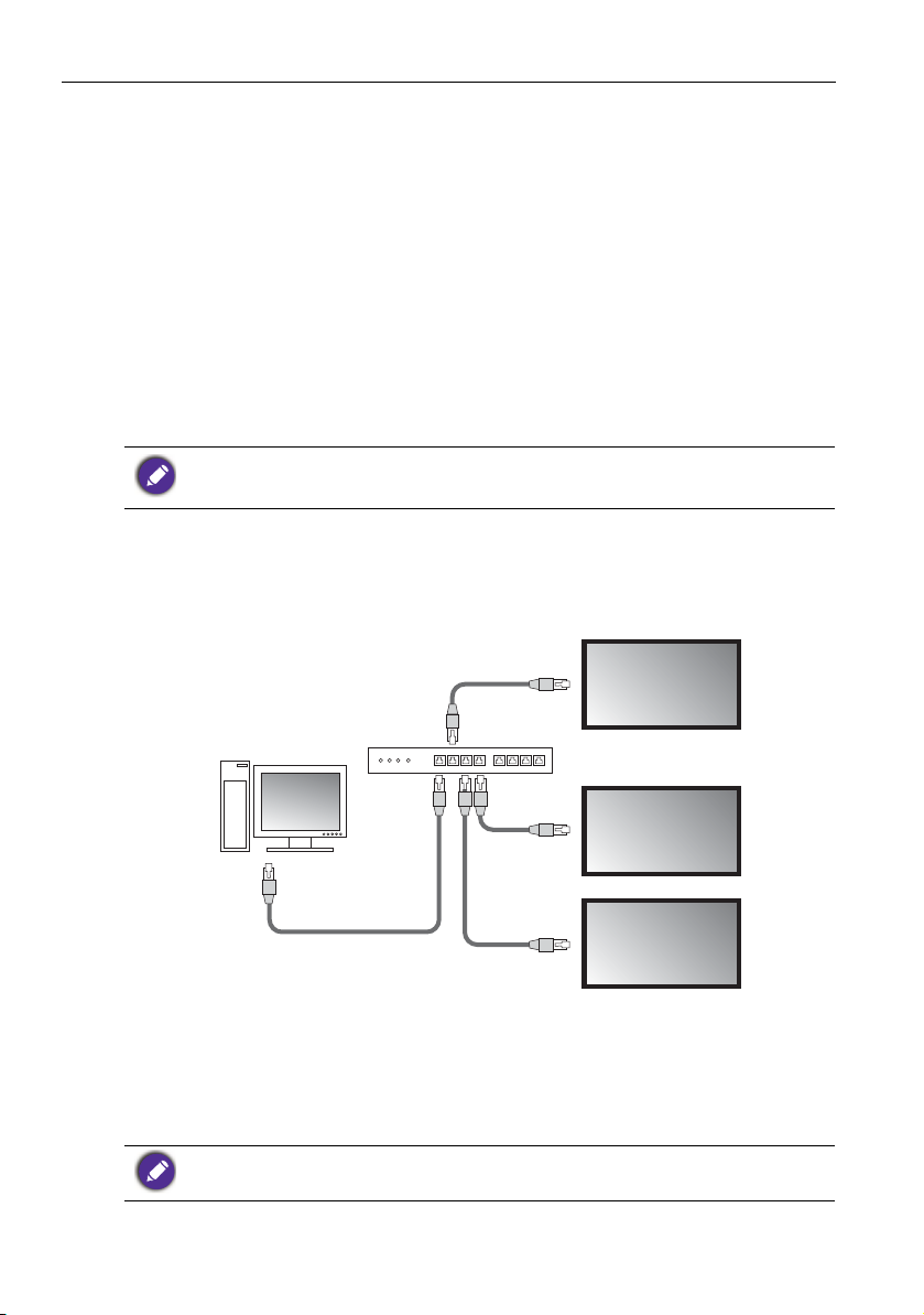
1. As illustrated in the figure below, connect the computer and displays to the Ethernet
LAN or WAN network via a hub, switch or router using RJ-45 cables.
2. Open the displays’ OSD menu and set the following settings:
• Set the Setting > Control Setting option to LAN.
• Set the Setting > Network Setting option to DHCP (if the IP address will be
automatically assigned by a DHCP server) or Manual (if the IP address has to be
assigned manually). You may need to contact your network administrator for assistance
on these settings.
If the Network setting is set to Manual, the computer and displays must have the same Subnet
mask, Default gateway, Primary DNS and Secondary DNS settings.
Page 7
Initial Setup 7
Computer
IN
OUT
IN
OUT
IN
Display
RS-232 cables
RS-232C connection
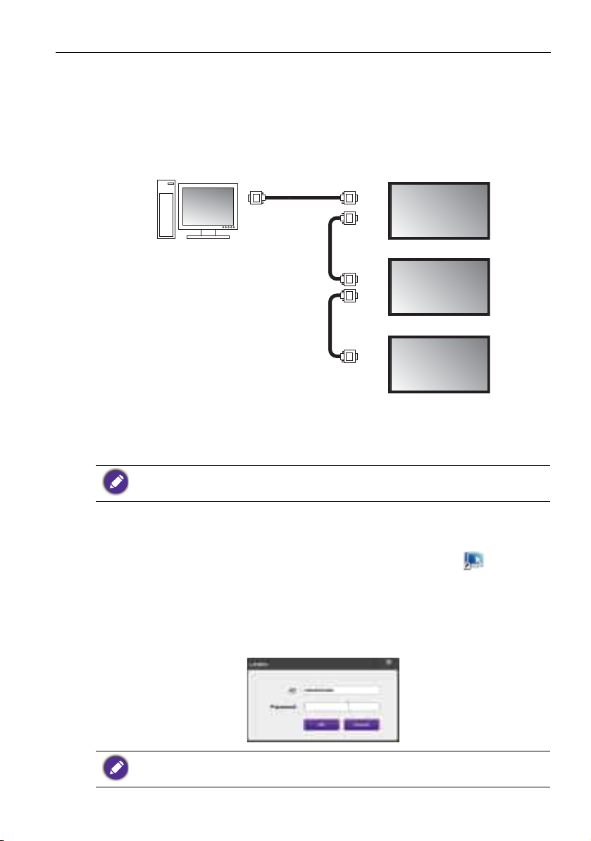
1. Connect the RS-232C port on the computer to the RS-232C IN port on the first display using a RS-232C cable.
2. Connect the RS-232C OUT port on the first display to the RS-232C IN port of the
second display using a RS-232 cable. Repeat this step to connect more displays. The
diagram below shows the general connection scheme.
3. Open the displays’ OSD menu and set the following settings:
• Set the Setting > Control Setting option to RS-232C.
• If you connect the computer to multiple displays, give each display a unique monitor ID
using the Setting > Set Monitor ID option.
Be sure to assign a unique monitor ID for each display. The Multiple Display Administrator uses
these IDs to identify and communicate with the displays.
Launching Multiple Display Administrator
To launch Multiple Display Administrator, click Windows Start button and select
Programs > MDA > MDA. You can also double-click the MDA icon on
Windows Desktop to launch the program.
The default password is 0000. If you change the default password, a dialog prompting
you to enter ID and password will appear. Enter the new password and click OK. The
dialog will not appear if the default password has not been changed. Multiple Display
Administrator home screen will appear if you are successfully logged in.
You can change the ID and password in the Security menu. Refer to Changing login ID and
password on page 28 for more information.
Page 8
Overview of components and functions8
1
2
3
4
Overview of components and functions
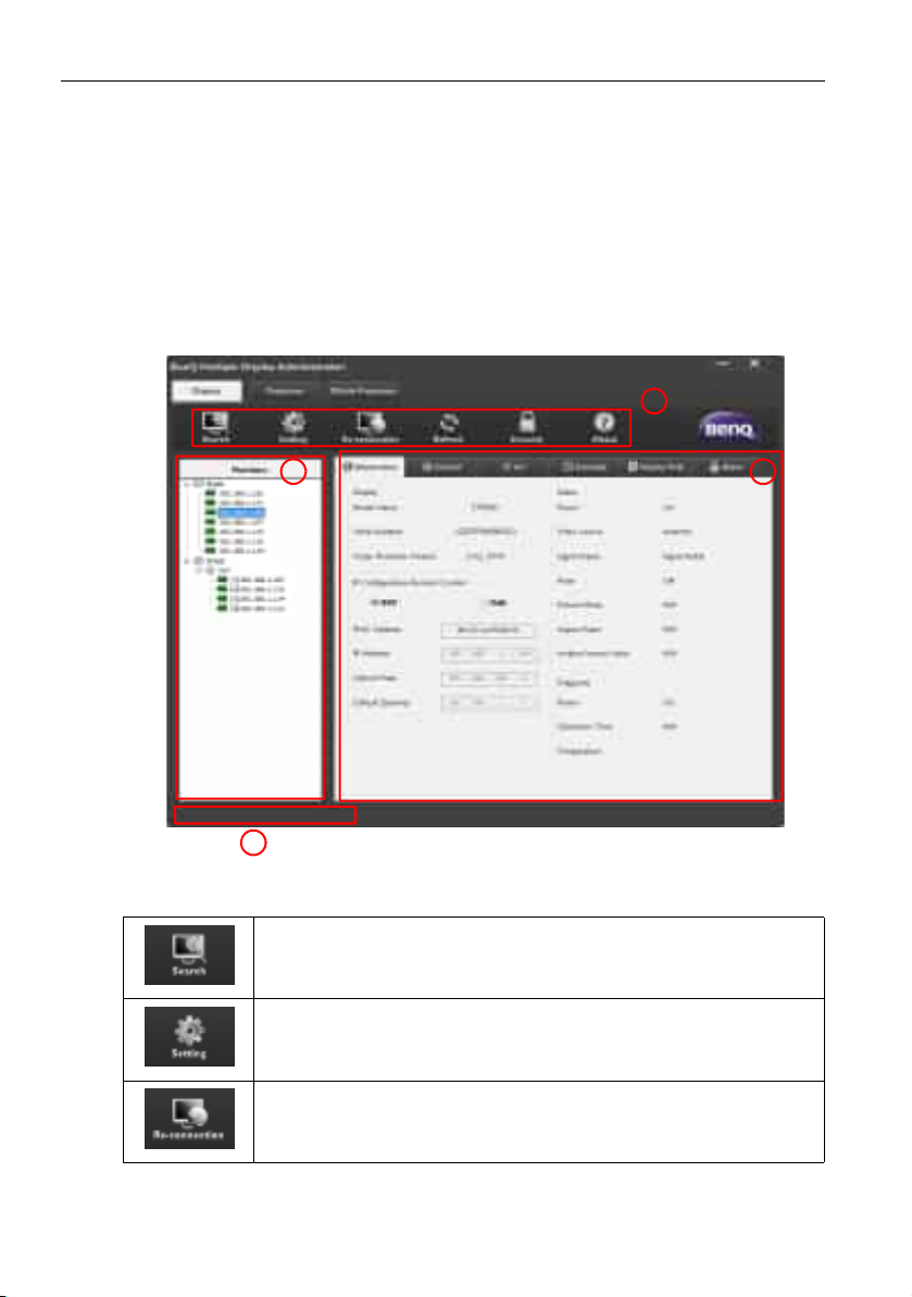
The Multiple Display Administrator home screen mainly consists of the following
components:
1. Toolbar: provides functions for connection and security settings.
2. Monitor list panel: lists displays that are connected to the computer and found on
the network.
3. Control panel: provides controls and settings for the display (and display groups)
selected on the Monitor list panel.
4. Notification area: shows notifications and results of command execution.
To o l b a r
Searches displays that are connected to the network and adds them to
the Monitor list panel.
Sets the connection mode between the computer and displays to
Network or Serial (RS-232C).
Allows you to manually re-connect to the display or display group
selected on the Monitor list panel.
Page 9
Refreshes the information and setting values on the Control panel
If the displays are connected via RS-232C connection, it may take some
time to refresh information on the tabs due to the connection speed.
Please wait until the information on the tabs is completely refreshed
before performing any further operations.
Ethernet connection RS-232C connection
(Information, Control, AV, Schedule, Display Wall and Alarm tabs).
Allows you to change the user ID and password that are required for
logging in to the Multiple Display Administrator.
Changes the program’s user interface language, shows software
version and opens the online Help.
Monitor list panel
Overview of components and functions 9
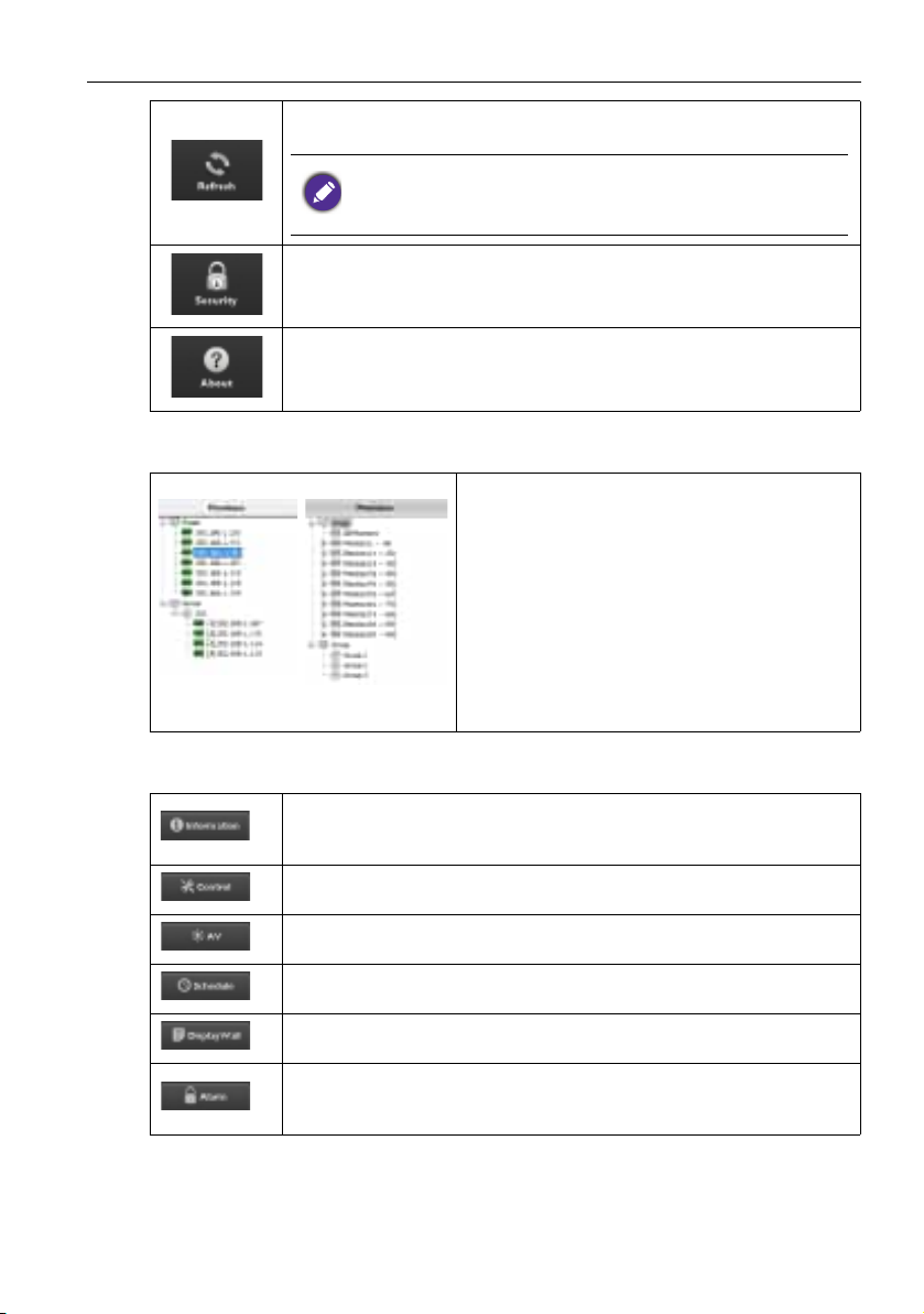
The Monitor list panel lists displays that are
currently connected to the computer and found
on the network.
• Displays found on the network will be listed
under the Single node.
• Display groups will be listed under the Group
node. You can create and edit display groups
for management purposes. For example, if you
select a display group and change settings on
the Control panel, the command will be sent to
all displays in the same display group.
Control panel
Shows information, current status and settings of the dsplay or display
group selected on the Monitor list panel. See Information tab on page
15 for details.
Provides controls for display’s power, volume, and other settings. See
on page 17 for details.
Provides controls for display’s audio and video settings. See AV tab on
page 19 for details.
Allows you to set different scheduled time intervals to automatically
turn on/off the display. See Schedule tab on page 20 for details.
Creates and adjusts a large screen matrix (display wall) for multiple
displays. See Additional operations on page 28 for details.
Configures email settings so that the Multiple Display Administrator
can send temperature warning and status report messages via email.
See Alarm tab on page 27 for details.
Page 10
Managing displays10
Managing displays
Searching for displays
After you finish connecting display(s) to the computer, what you need to do next is to let
the Multiple Display Administrator search for the displays and add them to the Monitor
list panel.
Serial (RS-232C) connection
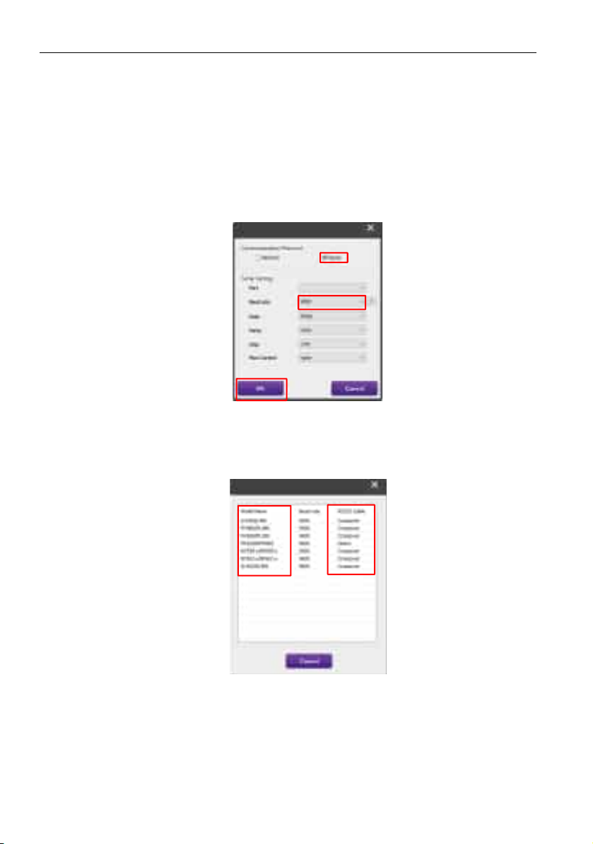
1. Click Search on the Toolbar. A dialog will appear asking you to specify the Communication Protocol.
2. Select Serial, and continue to select the Baud rate, Data, Parity, Stop, and Flow
Control.
3. Click OK. The Multiple Display Administrator will start searching for displays on the
RS-232C network, and will list the displays found on the Monitor list panel when
finished.
Page 11
Managing displays 11
Ethernet (LAN) connection
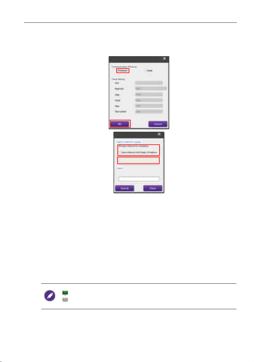
1. Click Setting on the Toolbar. A dialog will appear asking you to specify the Communication Protocol.
2. Select Network, and click OK. The dialog below will follow.
3. Click to select a suitable option:
• If you want the Multiple Display Administrator to search for all displays on the same
network, select Search Network for all Displays.
• If you only want to search for a display with a specific IP address, click Search
Network With Display IP Address, and then enter the IP address of the display.
4. Click Search. The Multiple Display Administrator will start searching for displays on
the network, and the progress will be indicated in the Status area.
5. Click Close when the search is complete. The display(s) found will be listed on the
Monitor list panel.
Managing displays on the Monitor list panel
After displays are searched and added to the Monitor list panel, you can perform various
operations to manage the displays.
The connection status of displays on the Monitor list panel is indicated by the icons below:
• : the display is connected (online).
• : the display is not connected (offline). You can click Re-connection on the Toolbar to
re-connect to the display.
Tagging a display
If displays are connected to the computer via Ethernet connection, they are named after
their IP addresses on the Monitor list panel by default. You can give these displays
different names (tags) for easier identification.
Page 12
Managing displays12
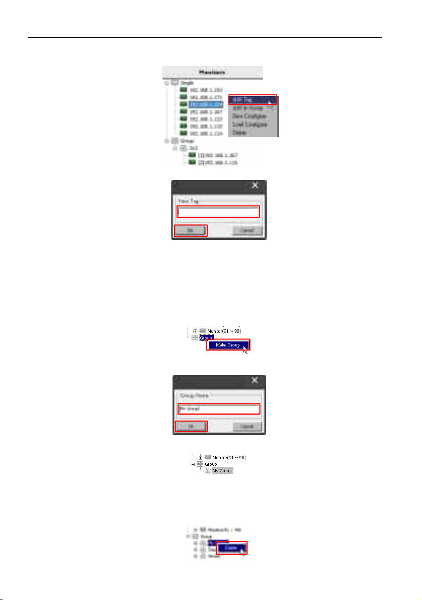
1. On the Monitor list panel, right-click on the display you want to add a tag, and select
Add Tag.
2. Enter the tag name in the dialog that follows, and click Set.
3. The tag you just added will appear in parentheses in front of the display’s IP address.
Creating a group
You can create display groups for management purposes. For example, if you select a
group and change settings on the Control panel, the command will be sent to all displays
in the same group.
1. On the Monitor list panel, right-click on the Group node, and select Make Group.
2. Enter the group name in the dialog that follows, and click OK.
3. A new group will be created under the Group node.
Deleting a group
1. On the Monitor list panel, right-click on the display group you want to delete, and
select Delete.
Page 13
Managing displays 13
2. The selected group will be deleted.
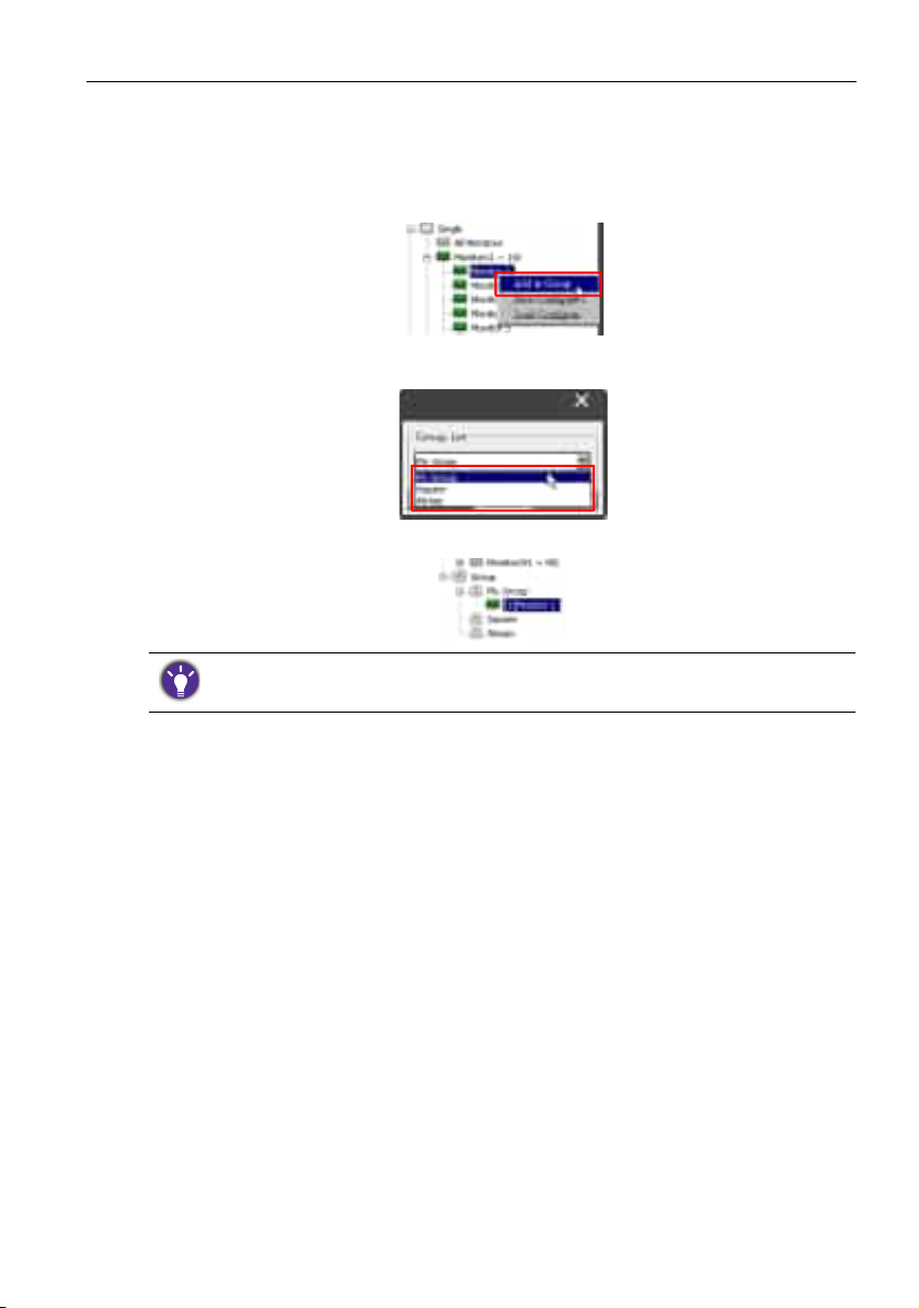
Adding displays to an existing group
1. On the Monitor list panel, right-click on a display you want to add to a display group
and select Add to Group.
2. In the dialog that appears, select the group to which the display will be added, and
then click Select.
3. The display will be added to the group you selected.
You can also drag a display and drop it to a group.
Page 14
Managing displays14
Deleting a display from a group
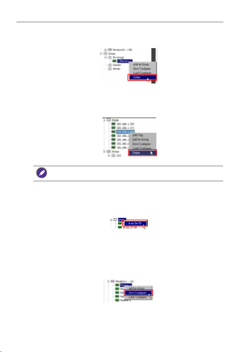
1. On the Monitor list panel, right-click on a display you want to delete from a display
group and select Delete.
2. The selected display will be deleted from the group.
Deleting a display from the Monitor list panel
1. On the Monitor list panel, right-click on the display you want to delete under the
Single node and select Delete.
2. The selected display will be deleted.
If a display is deleted under the Single node, it will also be deleted from the group to which it
belongs.
Setting display ID automatically
If displays are connected to the computer via Ethernet connection, you can use this
function to set IDs for the displays automatically.
1. On the Monitor list panel, right-click on the Single node and select Auto Set ID.
2. The IDs of the displays will be assigned automatically.
Saving and loading display configutation files
With this function, you can save display settings on the Control panel as a configuration
file (*.ini file) for backup purpose, and load the file when you want to restore these
settings.
1. On the Monitor list panel, right-click on a display and select Save Configure.
2. Specify the location where the file will be saved, and then click Save.
To load a configuration file, right-click on a display on the Monitor list panel and select
Load Configure.
Page 15
Setting up display configurations 15
Setting up display configurations
You can use the settings and options on the Control panel to remotely set up various
settings for a selected display or display group on the Monitor list panel.
Some controls and settings on the Control panel may not be available depending on your display
model. A warning message will appear in the Notification area on the lower left corner of the
program window if an unsupported control or setting is selected.
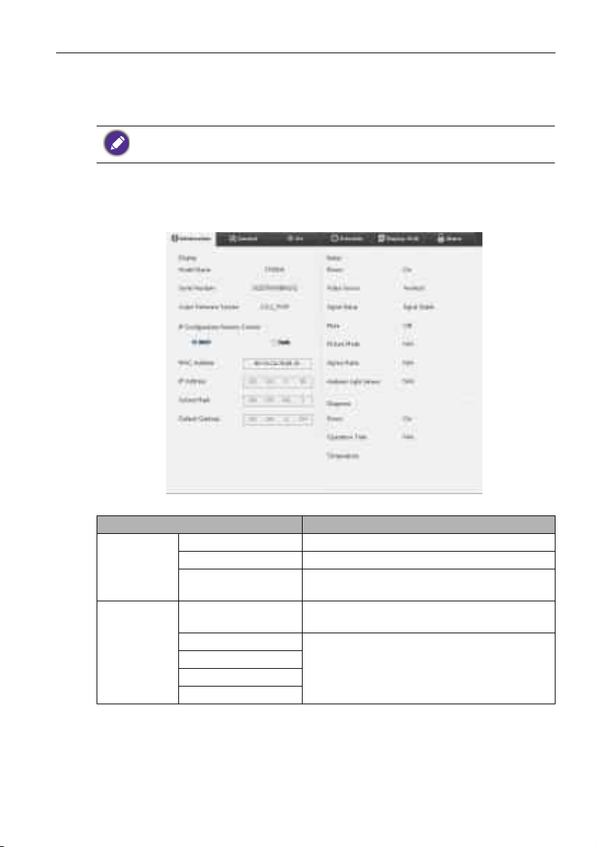
Information tab
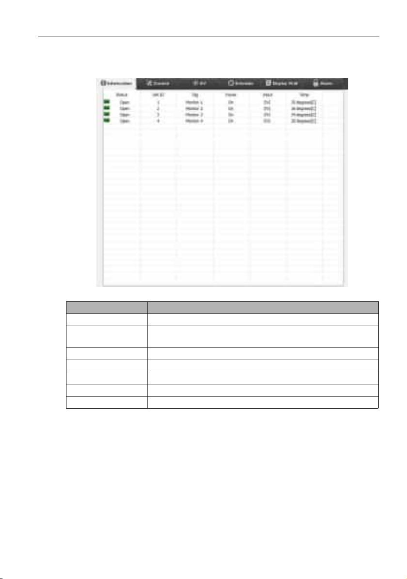
The following information will be provided on the Information tab when a display is
selected on the Monitor list panel.
Item Description
Model name Model name of the display.
Display
IP
Configuration
Remote
Control
Serial number Serial number of the display.
Scaler Firmware
Ve rs io n
DHCP/Static
MAC Address
IP Address
Subnet Mask
Default Gateway
Software (firmware) version of the display.
IP assignment method of current Ethernet
connection.
Network properties of current Ethernet
connection.
Page 16
Setting up display configurations16
Ethernet connection
Power Current power on/off status of the display.
Video Source Video input source being used by the display.
Signal Status Current input signal strength of the display.
Status
Mute Audio mute on/off status of the display.
Picture Mode Current picture mode setting of the display.
Aspect Ratio Current aspect ratio setting of the display.
Current on/off status of the display’s ambient
light sensor.
The diagnosis result for the display’s power
status.
Diagnosis
Ambient Light Sensor
Power
Operation Time The display’s total elapsed power on time.
Temperature The temperature inside the display.
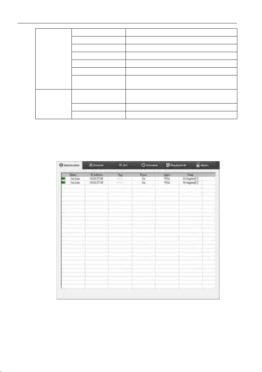
The following information of each display will be provided on the Information tab when a
display group is selected on the Monitor list panel.
Page 17
Setting up display configurations 17
RS232 group
Item Description
Status The network connection / RS232 status of each display.
IP Address (Ethernet
connection)
The IP address of each display.
Set ID (RS232 group) The Set ID of each display.
Tag The tag (name) given to each display.
Power The power on/off status of each display.
Input The input source current being used by each display.
Temp The temperature inside each display.
Page 18
Setting up display configurations18
Control tab
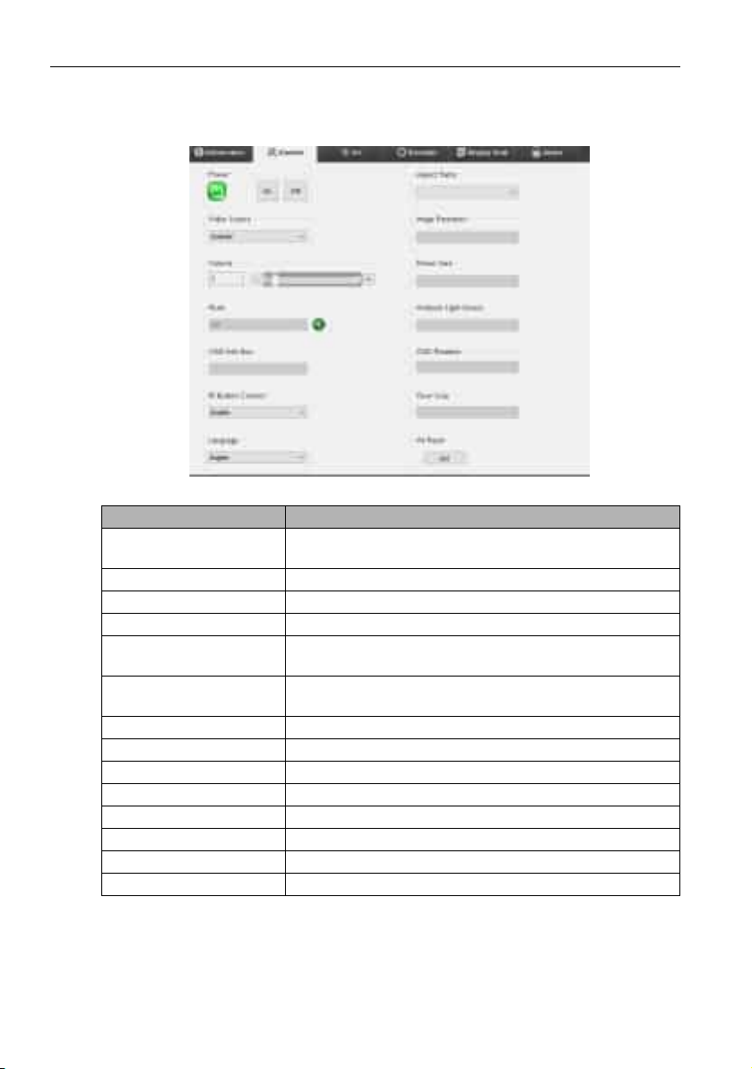
The Control tab consists of controls for basic display operations.
Item Description
Power
Video Source Selects a video input source.
Volume Adjusts audio volume.
Mute Mutes or unmutes audio output.
OSD Info Box
IR Button Control
Language Changes the language of the OSD menu.
Aspect Ratio Selects an image aspect ratio for the display.
Image Retention Turns on or off the image retention prevention function.
Power Save Changes the setting of the power save function.
Ambient Light Sensor Turns on or off the ambient light sensor of the display.
OSD Rotation Changes the orientation of the OSD menu.
Over Scan Changes the setting of the overscan function.
All Reset Resets all settings on the Control tab.
Tab on or off to turn on/off the power of the display or
puts the display to standby mode.
Enables (shows) or disables (hides) the on-screen
information box.
Turns on or off the remote control lock and key lock
functions.
Page 19

Setting up display configurations 19
AV tab
The AV tab contains controls for picture quality and sound settings.
Item Description
Picture Mode Selects a preset picture mode.
Backlight Adjusts the backlight intensity of the screen.
Contrast Adjusts the image contrast.
Brightness Adjusts the image brightness.
Chroma Adjusts the color intensity of the image.
Sharpness Adjusts the image sharpness.
Color Temp Adjusts the color temperature.
Auto Adjustment Execute
Speaker Selects the destination or device for audio output.
Balance
Sound Mode Selects a preset sound mode for audio output.
Treble Adjusts the audio treble.
Bass Adjusts the audio bass.
Click the Execute button to trigger the auto
adjustment function for VGA signal.
Adjusts the balance of volume between the left and
right speakers.
Page 20
Setting up display configurations20
Schedule tab
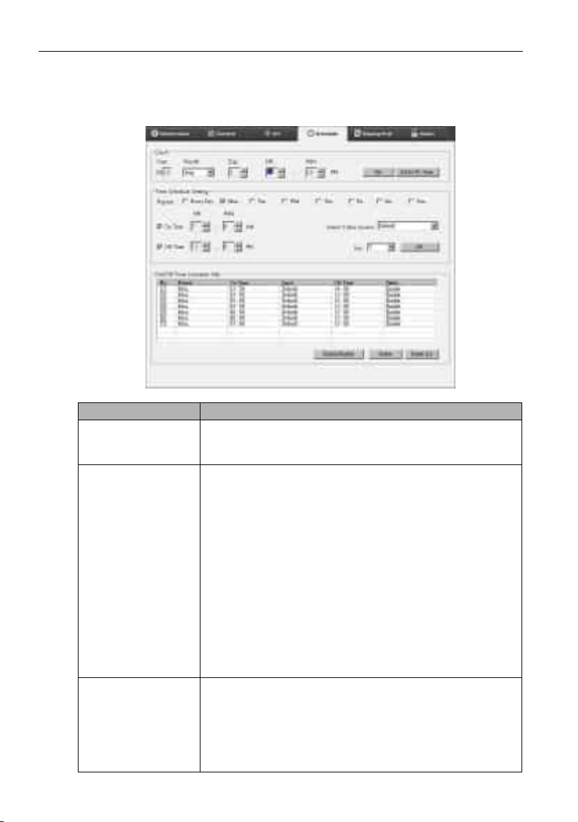
The Schedule tab provides controls by which you can set the display(s) to turn on or off
(enter standby mode) automatically.
Item Description
Clock
Time Schedule Setting
On/Off Time Schedule
Info
Allows you to set up current time manually. You can also click
Set by PC Time to set the display to use the current time
on the computer.
Allows you to specify on and off time schedules.
1. Set a repeat mode by checking a Repeat checkbox.
(Every Day, Mon., Tu e . ..., etc.)
2. Set On Time (the time when the display will be turned
on) and Off Time (the time when the display will be
turned off).
3. Select an input source that will be used when the display
is turned on from the Select Video Source drop-down
list.
4. Specify the number of the schedule in the No. drop-down
list.
5. Click the Set button to complete schedule settings. The
on/off time schedule will appear in the On/Off Time
Schedule Info area below.
Allows you to check and delete on/off time schedules.
• To enable or disable a time schedule, select a schedule and
then click Enable/Disable.
• To delete a time schedule, select a schedule you want to
delete, and then click Delete.
• To delete all time schedules, click Delete All.
Page 21
Setting up display configurations 21
Display Wall tab
Creating a display wall
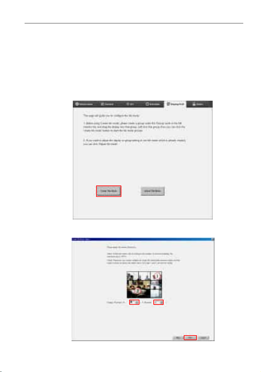
You can follow the step-by-step instructions on the Display Wall tab to create a display
wall that consists of multiple displays.
1. Create a display group, and add displays that will be used to create the video wall to
the group. Refer to Managing displays on the Monitor list panel on page 11 for how
to create a display group and add displays to a group.
2. Click to select the display group you created in step 1, and then click Create Tile
Mode on the Display Wall tab.
3. Sepcify the number of displays on the horizontal side (H. Monitors) and vertical
side (V. M o ni t o r s ) and then click Next.
Page 22
Setting up display configurations22
• You can create a display wall that consists of up to 10 x 10 displays.
• The number of displays in a display wall matrix should not exceed that in the display group
with which you use to create a display wall. Otherwise the Next button will be grayed out.
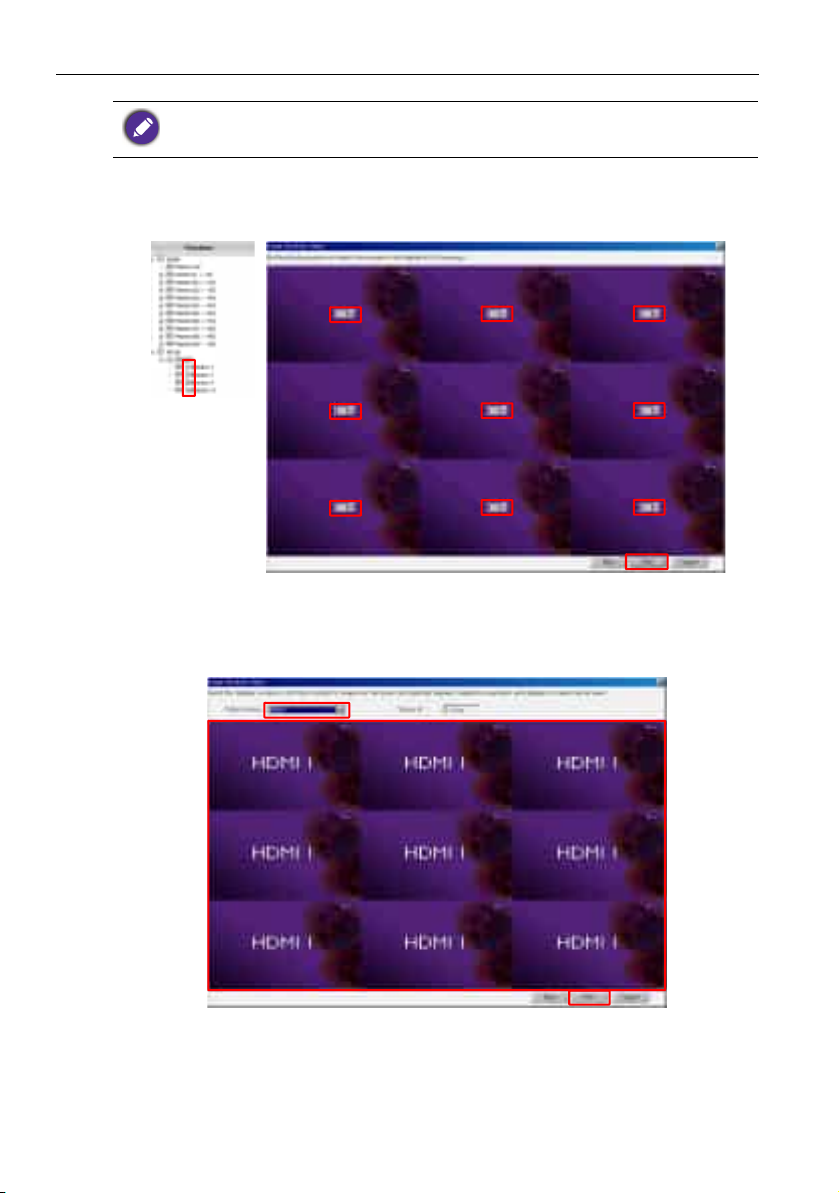
4. Select the position of each display in the display wall by selecting the monitor ID (as
shown in the Monitor list panel) of the display in each screen grid. Each screen grid
must have an unique monitor ID. Click Next to continue.
5. Select a video input source for the display.
Scenario 1: when a single input source is used for all displays
Select a video input source from the Video Source drop-down list, then click to
select all screen grids below. Click Next to continue.
Page 23
Setting up display configurations 23
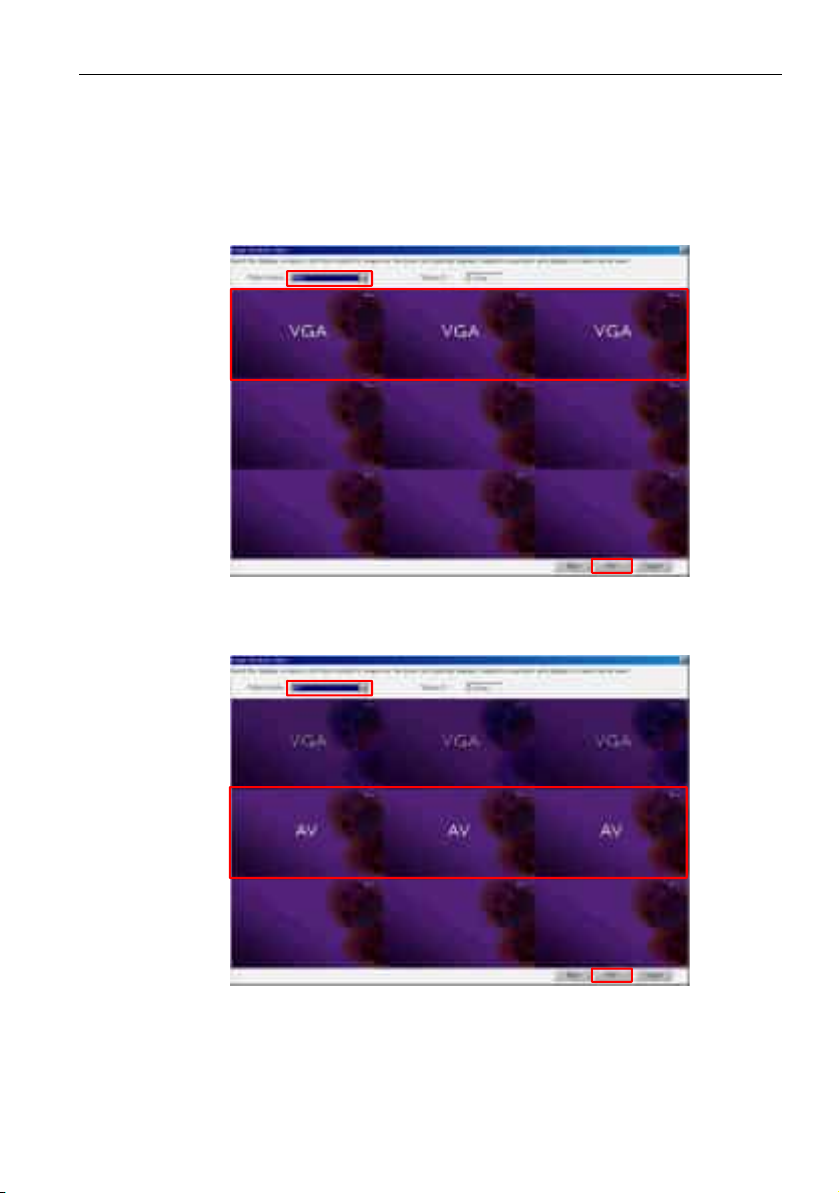
Scenario 2: when multiple input sources are used for different groups of
displays
The example below shows how to set up 3 different groups of displays that use 3 different input sources (VGA, AV and HDMI) in the same display wall.
a. Select VGA from the Video Source drop-down list, then click to select the
screen grids (displays) that will use the VGA input. This is display group 1 that uses
the VGA input. Click Next to continue.
b. Select AV from the Video Source drop-down list, then click to select the screen
grids (displays) that will use the AV input. This is display group 2 that uses the AV
input. Click Next to continue.
Page 24
Setting up display configurations24
Horizontal
position
Ve rt ic al
position
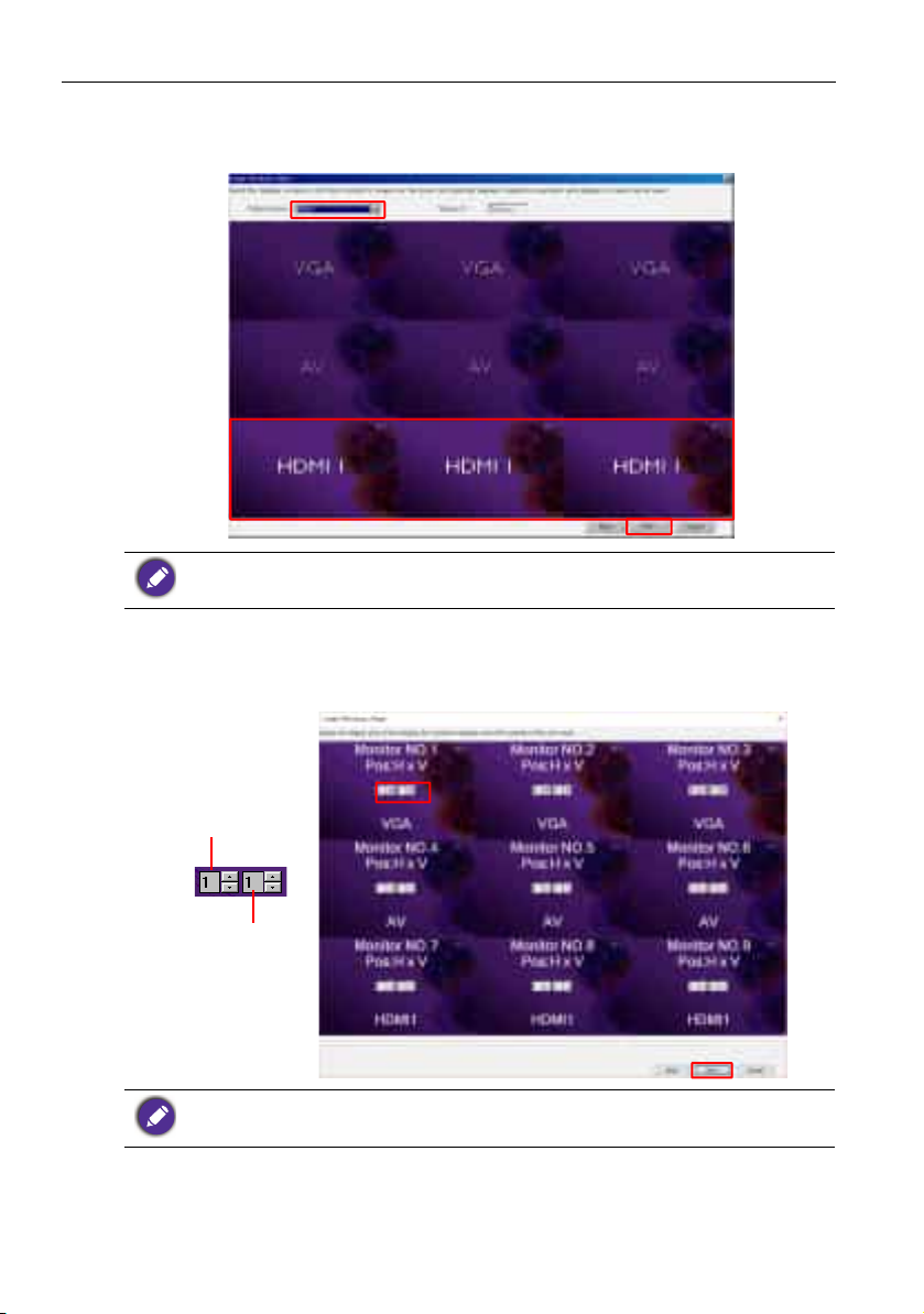
c. Select HDMI from the Video Source drop-down list, then click to select the
screen grids (displays) that will use the HDMI input. This is display group 3 that
uses the HDMI input. Click Next to continue.
You can follow similar steps to specify different combinations of input sources and displays.
6. You have the option to switch the position of each display in the display wall by
selecting a differnt horizontal or vertical position. Select a new position for the
display(s) using the horizontal position and vertical position boxes if necessary. Click
Next to continue.
If the display wall contains multiple display groups that use different input sources, you can only
change either the horizontal positon or vertical position (the horizontal position or vertical
position box will be grayed out), depending on the arrangement of displays.
Page 25
Setting up display configurations 25
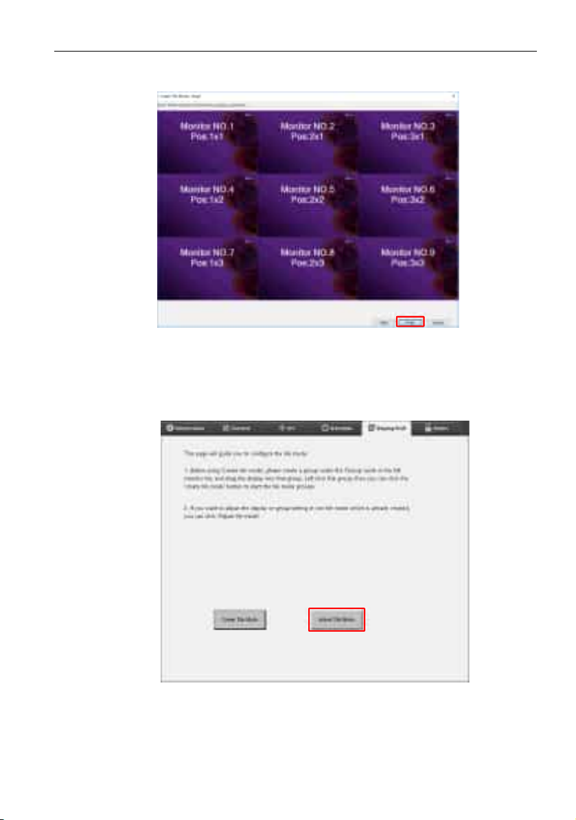
7. An overview of the display wall setup will follow. Check the setup and if it is OK,
click Finish to complete display wall settings.
Modifying display wall settings
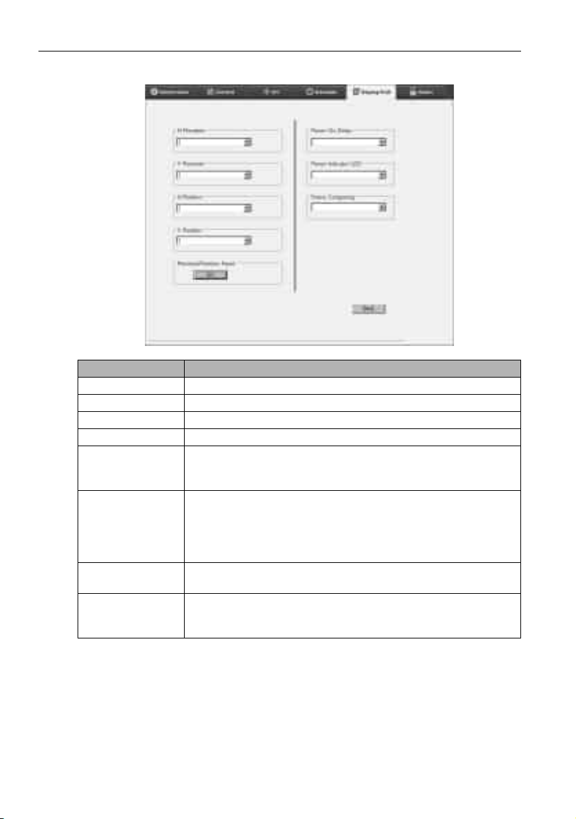
You can modify display wall settings of each display separately.
1. Click to select a display of a display wall group on the Monitor list panel.
2. Click Adjust Tile Mode on the Display Wall tab.
Page 26
Setting up display configurations26
3. Modify the settings as necessary.
Item Description
H. Monitors Specifies the number of displays on the horizontal side.
V. Monitors Specifies the number of displays on the vertical side.
H. Position Specifies the positon of the display on the horizontal side.
V. Position Specifies the position of the display on the vertical side.
Monitors/Position
Reset
Clicks the Set button to reset the display’s display wall settings,
including H. Monitors, V. Monitors, H. Position and V. Position
settings.
Enables (On) or disables (Off) the power on delay function. Once
enabled, when all displays in a display group are turned on at the
Power On Delay
same time using the Power function on the Control tab, this
feature automatically sets each display to power on at a slight
time difference to avoid sudden rise of power consumption.
Power Indicator
LED
Turns on or off the power indicator LED on the display.
Turns on or off the frame computing function of the display that
Frame Computing
automatically adjust the image to compensate for the width of the
monitor bezels in order to accurately display the image.
4. Click Back to save settings and return to the Display Wall tab.
Page 27
Setting up display configurations 27
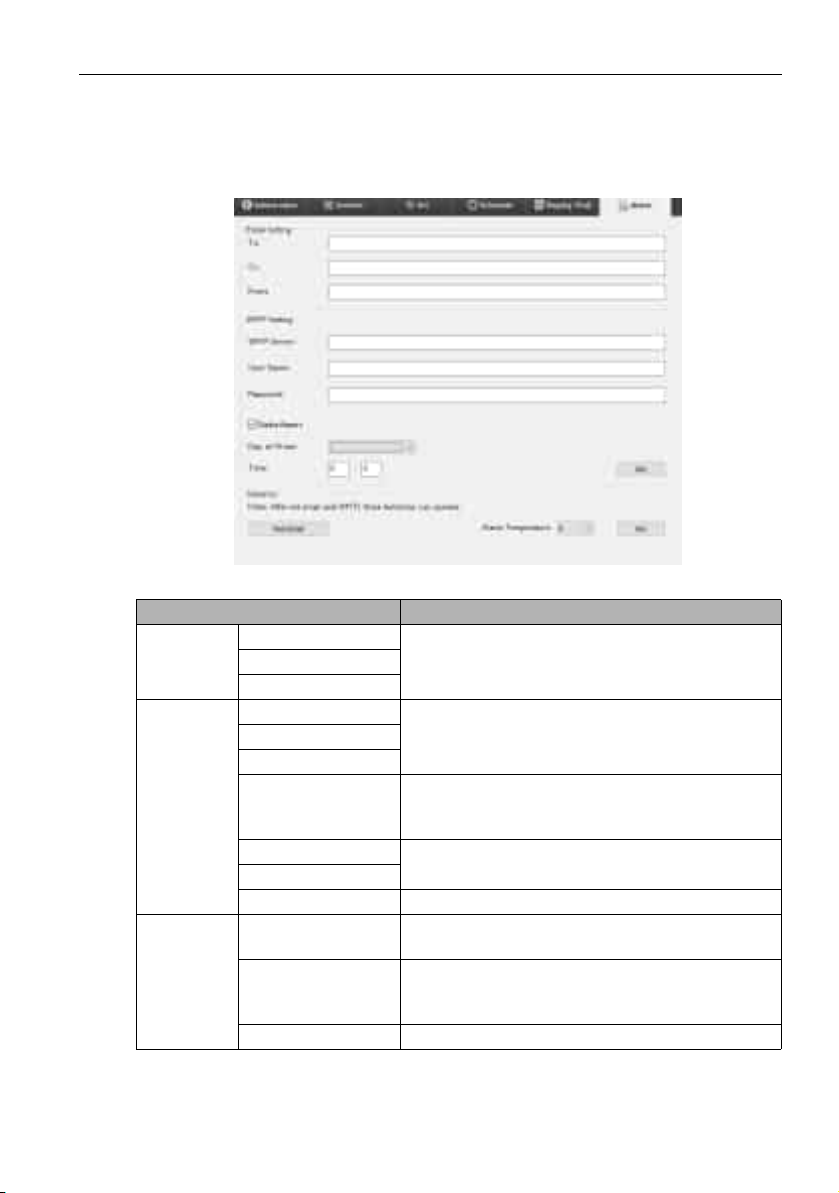
Alarm tab
The Alarm tab contains email settings that allow the Multiple Display Administrator to
send email messages to specified recipients when the internal temperature of the display
is too high, or when you have activated the status report function.
Item Description
Email
Setting
SMTP
Setting
Advance
To :
Specifies the recipients and sender of the email.CC:
From:
SMTP Server
Specifies the SMTP settings.User Name
Password
Checks this checkbox to let the Multiple Display
Status Report
Day of Week
Time
Set button Clicks this button to save settings.
Te s t E m a i l button
Alarm temperature
Set button Clicks this button to save settings.
Administrator send a status report of the
display(s) via email at a specific time.
Specifies the time at which the status report will
be sent.
Clicks this button to send a test email when the
setting is completed.
Specifies the temperature limit. If the display’s
internal temperature exceeds this limit, a warning
email message will be sent.
Page 28
Additional operations28
Additional operations
Changing login ID and password
You can change the ID and password that are used to log in to the Multiple Display
Administrator.
The ID and password can be changed, however, you cannot create multiple ID and password
combinations.
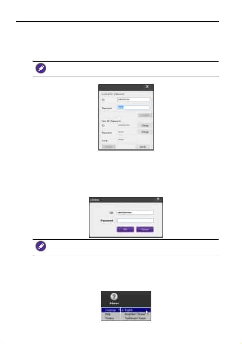
1. Click Security on the Toolbar. The following dialog will appear.
2. Enter current ID and password in the ID and Password fields, and then click
Confirm. If the ID and password are verified successfully, you can continue to the
next step.
3. Enter the new ID and password in the ID, Password and Ve ri fy fields below, and
then click Change.
4. If you change the default password 0000, a reminder dialog will appear whenever
you log in
. The dialog will not appear if the default password has not been changed.
The ID and password are case-sensitive. You can use alphanumeric and special characters such
as !,@,#,$,%,&,*,-,_,=,+,? for the ID and password.
Changing language
You can change the user interface language of the Multiple Display Administrator
whenever necessary.
To change language, click About on the Toolbar and select a preferred language.
1/25/16
Page 29
Troubleshooting 29
Troubleshooting
If you encounter problems while using the Multiple Display Administrator, please refer to
the following troubleshooting tips to try to solve the problems by yourself. If the
problem persists, please contact BenQ Customer Support for help.
Problem Solution
Check the following:
Cannot connect to the
display(s)
• Check the cable connection. Is the display correctly
connected to the computer?
• Is the display turned on?
• Is the COM port setting correct?
• Is the display’s network setting correct?
 Loading...