

Page 1

Form No:JBS72-C5-501 - 4 - Confidential □ High ■ Medium □ Low
JBS72 System Disassembly Description
2. Disassembly Steps
1.0 BATERRRY/Remote Control
1.1 RAM Module
1.2 HDD
1.3 ODD
1.4 Keyboard
1.5 WLAN Card
1.6 Speaker
1.7 Top Case
A. TouchPad:
(Mylar/ FFC/ button bracket/button board)
B. HotKey Board
1.8 LCD Module
A. LCD Bezel
B. Inerter
C. Hinge Cover
D. LCD Cover
E. LCD Bracket
F. Panel Unit
1.9 Thermal Module
2.0 CPU
2.1 Modem Module/RJ11 Cable/DC-In Board
2.2 Audio Transfer Board/ Speaker cable/Audio I/O
Board
2.3 Mother Board/ VGA I/O Board
Page 2
Form No:JBS72-C5-501 - 6 - Confidential □ High ■ Medium □ Low
JBS72 System Disassembly Description
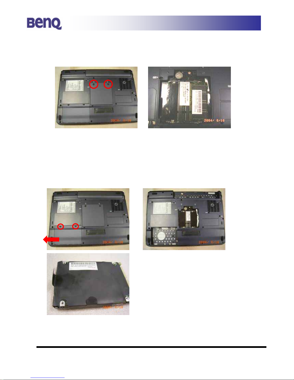
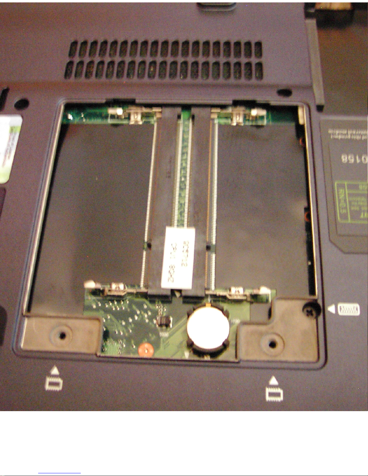
1.1 RAM MODULE
1) Remove 2 screws and RAM door can be removed.
2) Release the RAM catch on both side. RAM module can be removed.
1.2 HDD ( Hard Disk Drive )
1) Remove 2 screws and HDD door can be removed .
2) Pull the HDD carefully with black tape.
Page 3
Page 4
Form No:JBS72-C5-501 - 7 - Confidential □ High ■ Medium □ Low
JBS72 System Disassembly Description
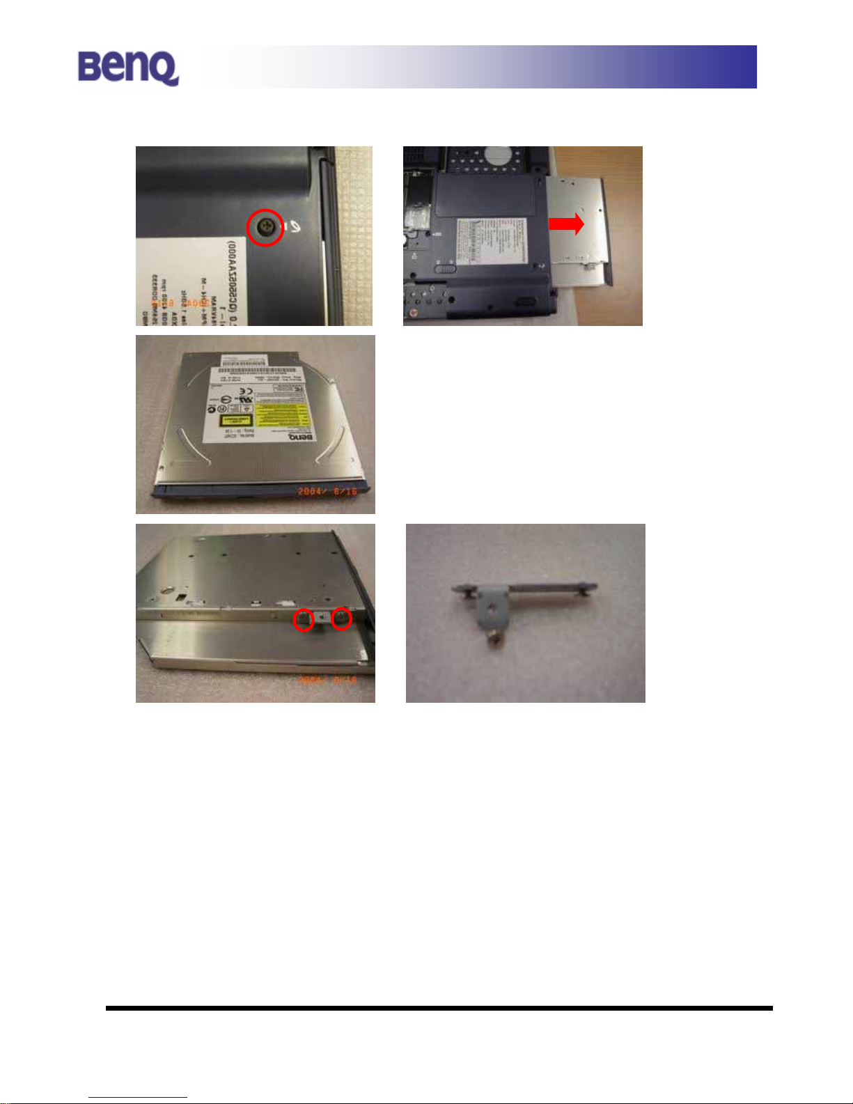
1.3 ODD ( Optical Disk Drive )
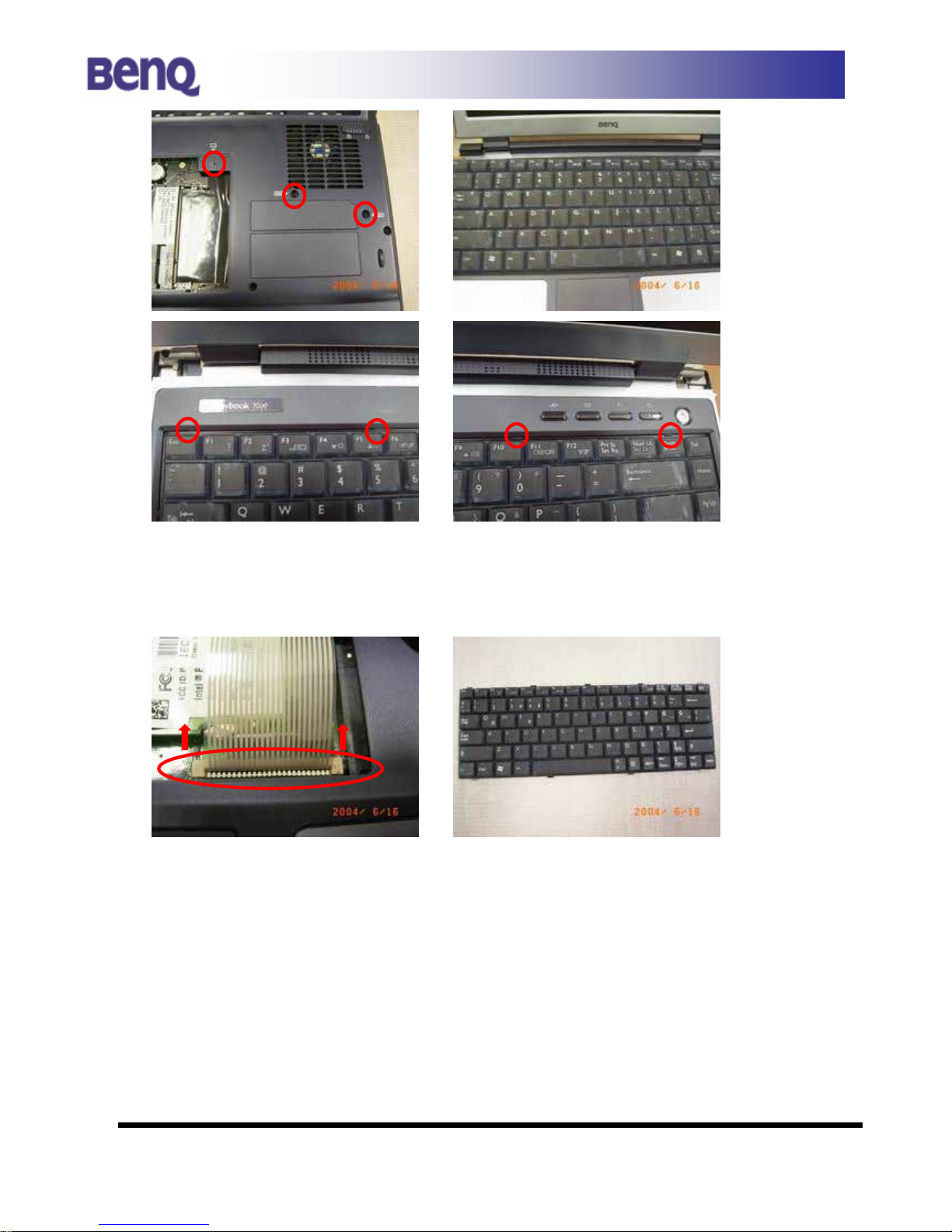
1.4 KeyBoard
1) Remove Ram Door first.
2) Remove 3 screws as indicated.
Page 5
Form No:JBS72-C5-501 - 8 - Confidential □ High ■ Medium □ Low
JBS72 System Disassembly Description
2) Turn over the Joybook and release the latch of keyboard as shown.
3) Disconnect the keyboard cable then keyboard can be removed.
1.5 Wireless LAN Board
1) Remove Keyboard first as above steps.
2) Remove the wireless antenna connector on board as shown
Page 6
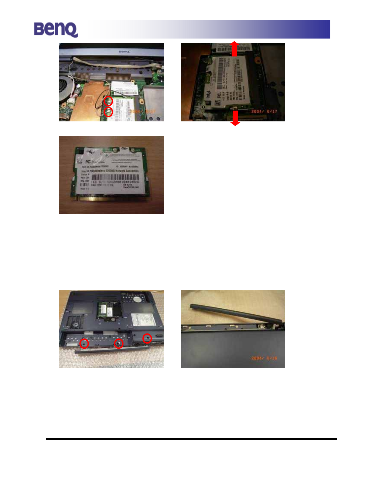
Form No:JBS72-C5-501 - 9 - Confidential □ High ■ Medium □ Low
JBS72 System Disassembly Description
[The main wire color: Gray ]
1.6 Speaker
1) Remove Battery first.
2) Release 3 screws on battery space as shown.
2) Release the cable on speaker then separate the speaker module.
Page 7
Form No:JBS72-C5-501 - 10 - Confidential □ High ■ Medium □ Low
JBS72 System Disassembly Description
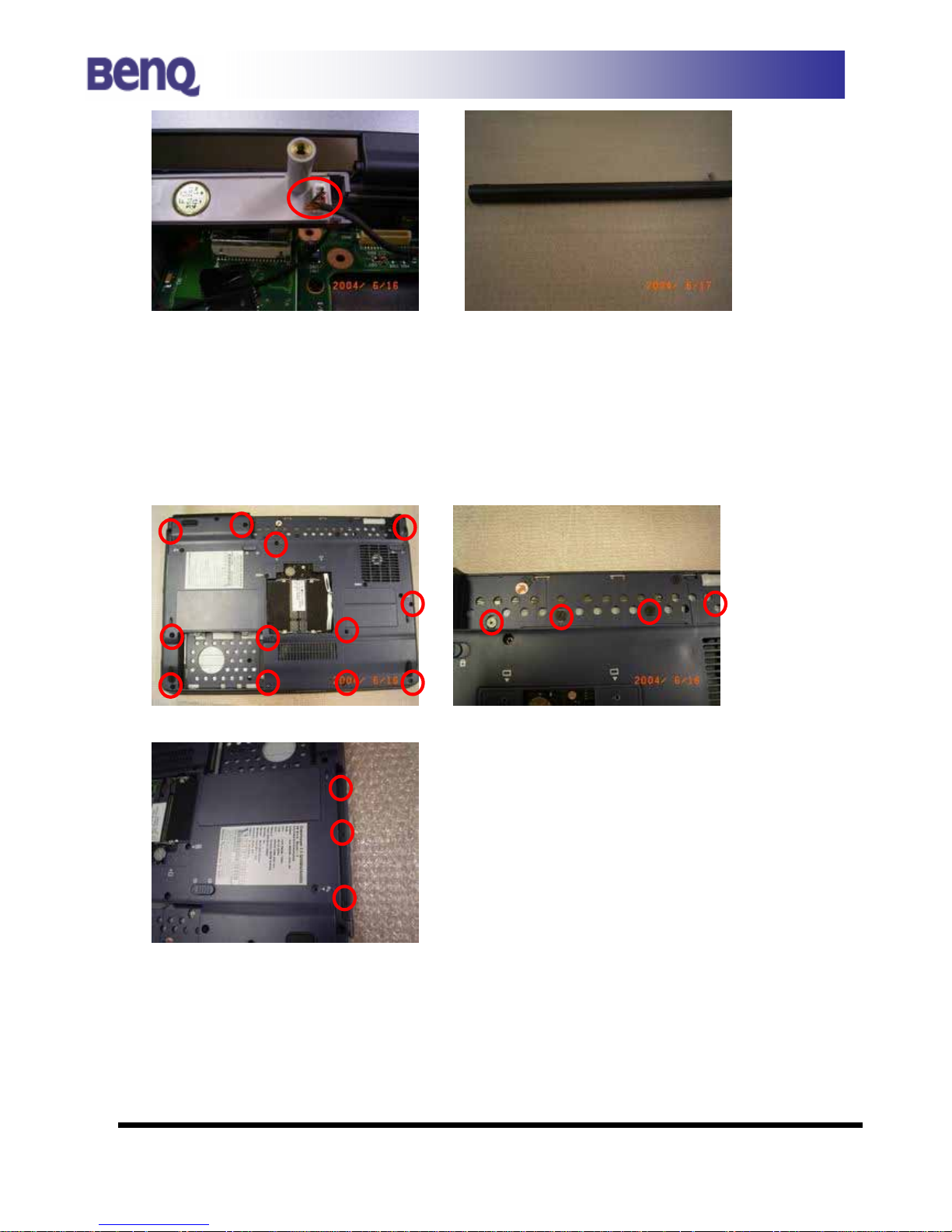
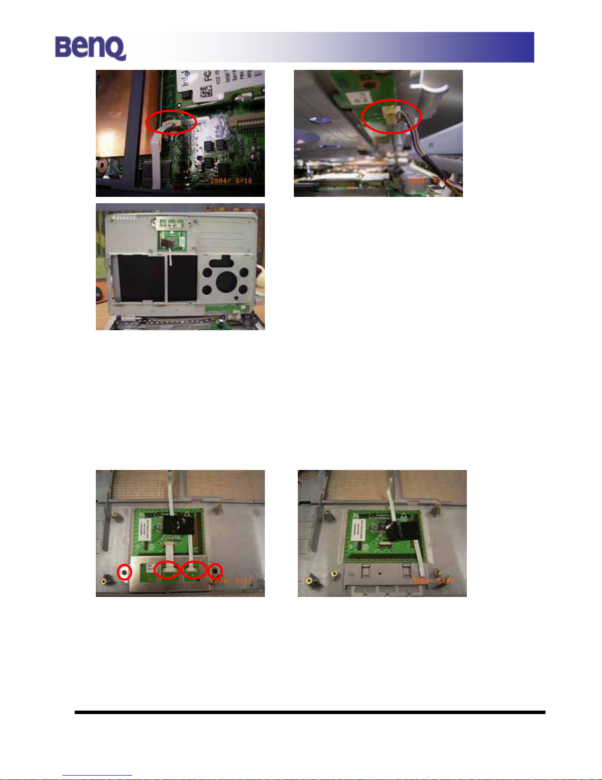
1.7 Top Case
1) Release 12 screws on the bottom case.
2) Release 4 screws on the bottom of battery.
3) Remove ODD first then release 3 small screws.
4) Remove the Touchpad FFC and Hot key board Cable as indicated.
Page 8
Form No:JBS72-C5-501 - 11 - Confidential □ High ■ Medium □ Low
JBS72 System Disassembly Description
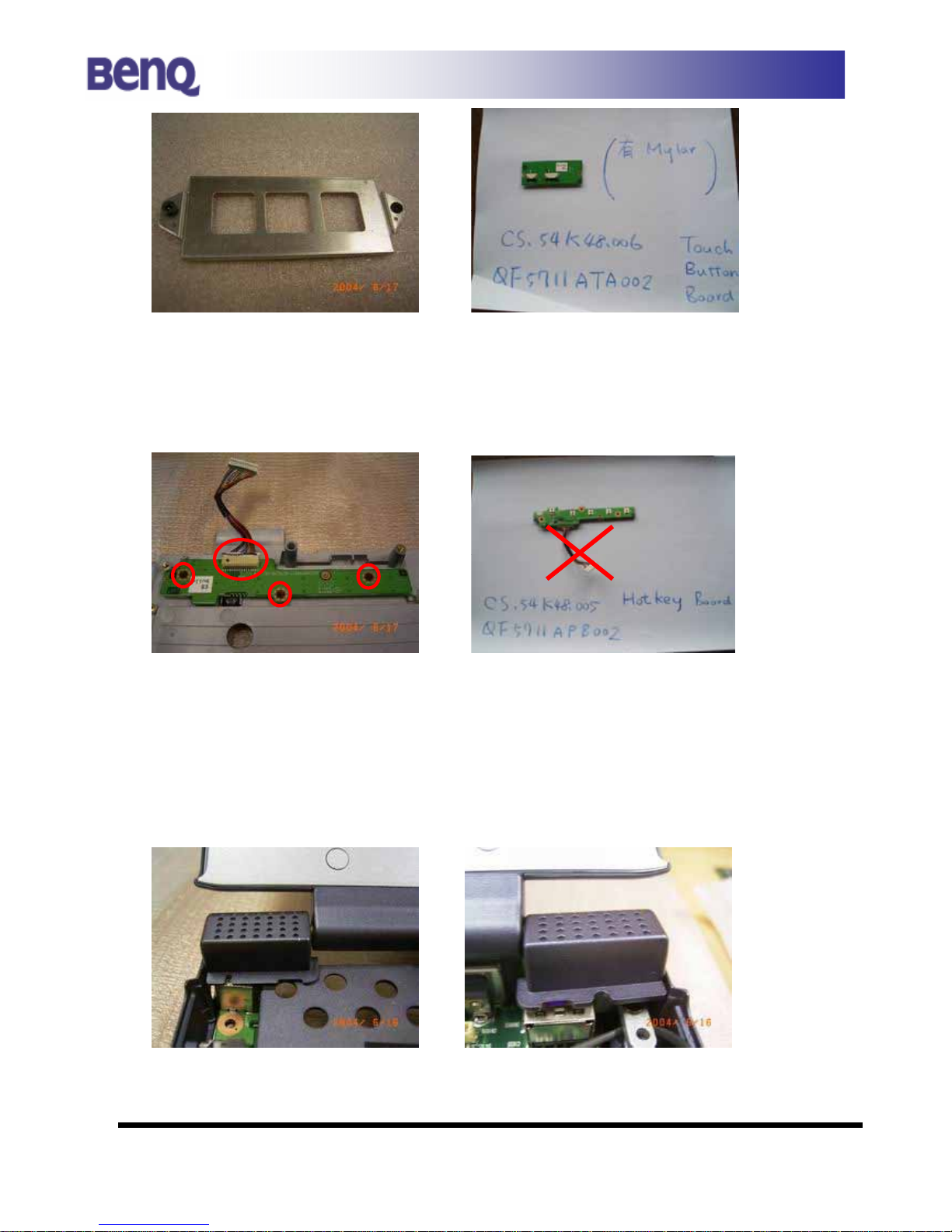
A. TouchPad (Mylar/ FFC/ button bracket/button board)
1) Tear down the mylar on touchpad.
2) Release 2 screws on the touch pad button bracket.
3) Release 2 FFC as indicated.
4)
3) Separate touch pad button board and bracket.
Page 9
Form No:JBS72-C5-501 - 12 - Confidential □ High ■ Medium □ Low
JBS72 System Disassembly Description
B. Hotkey Board
1) Release 3 screws on hotkey board.
2) Release cable as indicated, then separate hotkey board.
1.8 LCD Module
1) After Step 1.7 (Remove Top Case first).
2) Remove 2 switch covers carefully.
Page 10

Page 11

Form No:JBS72-C5-501 - 14 - Confidential □ High ■ Medium □ Low
JBS72 System Disassembly Description
A. LCD Bezel
1) Release 2 screw rubbers and screws on LCD Bezel.
2) Remove LCD Bezel.(Direction: Inside to outside)
B. Inverter
1) Remove inverter cable.
Page 12

Form No:JBS72-C5-501 - 5 - Confidential □ High ■ Medium □ Low
JBS72 System Disassembly Description
1.0 BATTERY /Remote Control
1) Reverse Joybook .
2)Move battery locker and battery can be lift .
3) Remote Control
Push the PC Card Ejection Button from the left side of machine.
You can Get remote Control.
Page 13

Form No:JBS72-C5-501 - 15 - Confidential □ High ■ Medium □ Low
JBS72 System Disassembly Description
C. Hinge Cover
1) Release 2 screws on hinge cover(L/R).
Page 14

Form No:JBS72-C5-501 - 13 - Confidential □ High ■ Medium □ Low
JBS72 System Disassembly Description
2) Release 2 screws as shown.
3) Release 2 screws on LCD bracket as shown.
4) Release LCD Cable then take out the LCD module.
Page 15

Form No:JBS72-C5-501 - 16 - Confidential □ High ■ Medium □ Low
JBS72 System Disassembly Description
D. LCD Cover
1) Release 2 screws on LCD Bracket(L/R).
2) Release 4 screws on LCD Bracket(L/R).
5) Then separate Panel Unit and LCD Cover.
4) Release 2 screws on antenna as indicated.
Page 16

Form No:JBS72-C5-501 - 17 - Confidential □ High ■ Medium □ Low
JBS72 System Disassembly Description
E. LCD Bracket
1) Release 4 screws on both side of panel then LCD and bracket
can be separated.
F. Panel Unit
1) Release panel cable carefully.
Page 17

Form No:JBS72-C5-501 - 18 - Confidential □ High ■ Medium □ Low
JBS72 System Disassembly Description
1.9 Thermal Module
1) Release 4 screws on Heatsink.
3)
Remove 2 screws and cable on Thermal Fan.
Page 18

Form No:JBS72-C5-501 - 19 - Confidential □ High ■ Medium □ Low
JBS72 System Disassembly Description
2.0 CPU
1) After 1.9 step, loose the flat screw then CPU can be taken out.
2.1 Modem Module/RJ11 Cable/DC-In Board
1) Remove 2 screws and cable on modem as shown.
2) Release DC-In Board connector.
3) Carefully tear the tape then separate RJ11 Cable and DC-In board.
Page 19

Form No:JBS72-C5-501 - 20 - Confidential □ High ■ Medium □ Low
JBS72 System Disassembly Description
2.2 Audio Transfer Board/ Speaker cable/
Audio I/O Board
1) Remove FFC on audio board. (Place: Above Audio I/O Board)
2) Release the speaker cable and mic cable as shown.
3) Carefully release connector and remove the audio transfer board.
Page 20

Form No:JBS72-C5-501 - 21 - Confidential □ High ■ Medium □ Low
JBS72 System Disassembly Description
1) Remove 2 screws then detach Audio I/O board as shown.
2.3 Motherboard/ VGA I/O board
1) Remove PCMCIA Dummy card.
2) Remove 2 screw in VGA connector board.
2) Remove 1 screw on PCMCIA Bracket and 1 screw on MB.
3) Carefully detach Motherboard.
Page 21

Page 22

Page 23

Page 24

Page 25

Page 26

Form No:JBS72-C5-501 - 22 - Confidential □ High ■ Medium □ Low
JBS72 System Disassembly Description
4) Remove 2 screws as indicated then carefully separate VGA I/O board
and Motherboard.
Page 27

Page 28

 Loading...