

Page 1

InstaShow™ S
User Manual
WDC20
V 1.00
Page 2

Copyright
Copyright © 2019 by BenQ Corporation. All rights reserved. No part of this publication may be
reproduced, transmitted, transcribed, stored in a retrieval system or translated into any language or
computer language, in any form or by any means, electronic, mechanical, magnetic, optical, chemical,
manual or otherwise, without the prior written permission of BenQ Corporation.
Disclaimer
BenQ Corporation makes no representations or warranties, either expressed or implied, with
respect to the contents hereof and specifically disclaims any warranties, merchantability or fitness for
any particular purpose. Further, BenQ Corporation reserves the right to revise this publication and
to make changes from time to time in the contents hereof without obligation of BenQ Corporation
to notify any person of such revision or changes.
This user manual aims to provide the most updated and accurate information to customers, and thus
all contents may be modified from time to time without prior notice. Please visit www.benq.com for
the latest version of this manual.
The illustrations and the images in this guide are for your reference.
BenQ ecoFACTS
BenQ has been dedicated to the design and development of greener product as part of its aspiration
to realize the ideal of the “Bringing Enjoyment 'N Quality to Life” corporate vision with the ultimate
goal to achieve a low-carbon society. Besides meeting international regulatory requirement and
standards pertaining to environmental management, BenQ has spared no efforts in pushing our
initiatives further to incorporate life cycle design in the aspects of material selection, manufacturing,
packaging, transportation, using and disposal of the products. BenQ ecoFACTS label lists key ecofriendly design highlights of each product, hoping to ensure that consumers make informed green
choices at purchase. Check out BenQ's CSR Website at http://csr.BenQ.com/ for more details on
BenQ's environmental commitments and achievements.
2
Page 3

Table of contents
Copyright ...................................................................................................................................... 2
Disclaimer ..................................................................................................................................... 2
BenQ ecoFACTS ......................................................................................................................... 2
Introduction .................................................................................................................................. 5
Product features .............................................................................................................................................. 6
Package content ............................................................................................................................................... 7
Product specification ....................................................................................................................................... 8
Overview ........................................................................................................................................................... 9
Button .............................................................................................................................................................................................. 9
Host ................................................................................................................................................................................................. 9
LED indicators of the Button and the Host ......................................................................................................................... 10
Installation ...................................................................................................................................11
Environment check .....................................................................................................................................................................11
Assembling the Host .....................................................................................................................................12
Setting up the Host .......................................................................................................................................12
Attaching the Host to the ceiling ............................................................................................................................................ 12
Attaching the Host to a ceiling mount................................................................................................................................... 13
Placing the Host on a table ....................................................................................................................................................... 13
Installing the Host on the wall or trolley .............................................................................................................................. 15
Positioning the Host antennas ....................................................................................................................16
For ceiling installation ................................................................................................................................................................16
For ceiling mount installation ................................................................................................................................................... 16
For table placement ................................................................................................................................................................... 17
Connecting the HDMI cable and power ..................................................................................................17
Assembling the adapter ............................................................................................................................................................. 18
Connecting the HDMI cable..................................................................................................................................................... 19
Power supply via a power adapter .........................................................................................................................................19
LAN connection ..........................................................................................................................................................................20
Setting up and powering a Button .............................................................................................................20
Using Cable USB A(F) to USB A(M) .........................................................................................................22
Pairing a Button and Host ............................................................................................................................23
When the Host is placed on a table ....................................................................................................................................... 23
Storing Buttons and USB cable in the cradle ..........................................................................................25
Resetting a Host ............................................................................................................................................ 25
Resetting a Button .........................................................................................................................................26
Starting and stopping presentations ......................................................................................28
Getting ready ..................................................................................................................................................28
Starting presentation .....................................................................................................................................28
Idle presentation ............................................................................................................................................29
Split screen presentations ............................................................................................................................30
Starting a split screen presentation ........................................................................................................................................ 30
Switching from a split screen to a full screen presentation .............................................................................................. 31
Presenting with mobile devices ..................................................................................................................31
Touch back ...................................................................................................................................................... 33
Web management .....................................................................................................................34
Accessing the web management interface ...............................................................................................34
Logging into the web management interface via direct connection ...............................................................................34
Logging into the web management interface via LAN........................................................................................................ 36
3
Page 4

Logging into the web management interface via a wireless network ............................................................................. 36
Getting started ...............................................................................................................................................38
Top command buttons ..............................................................................................................................................................38
Function bar .................................................................................................................................................................................38
Main column .................................................................................................................................................................................39
Information ...............................................................................................................................................................................39
WAN ............................................................................................................................................................................................. 41
Wireless Network .................................................................................................................................................................. 42
Pairing ......................................................................................................................................................................................... 48
Advance Setting..................................................................................................................................................................... 51
Scheduling ..................................................................................................................................................................................... 56
Tool ............................................................................................................................................................................................... 57
Legal Announcement ................................................................................................................................................................. 66
Troubleshooting ........................................................................................................................ 67
4
4/9/19
Page 5
Introduction
InstaShow™ S (or “the product” in this document) is a wireless device for corporate meeting rooms.
Users expect devices to respond instantly, apps to launch and to control at their fingertips, and
information to be available on demand. The product bypasses the complicated steps of IP addresses,
driver installation, app execution, setting selection, etc. to quickly deliver professional, stable visual
quality for teams to collaborate freely and confidently. The product is an unique all-hardware solution
without software issues for universal compatibility and display flexibility.
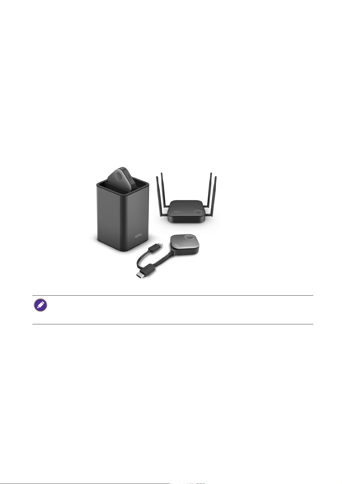
A standard product set consists of an InstaShow™ S Host (or “Host” in this document) and two
InstaShow™ S Buttons (or “Buttons” in this document). Depending on the location where you buy
the product, the software of the base unit can be different. You can buy additional InstaShow™ S
Button kits if needed.
• “InstaShow™ S” will hereinafter be referred to as “the product” in this document.
• “InstaShow™ S Host” will hereinafter be referred to as “Host” in this document.
• “InstaShow™ S Button/Buttons” will hereinafter be referred to as “Button”/“Buttons” in this document.
5 Introduction
Page 6
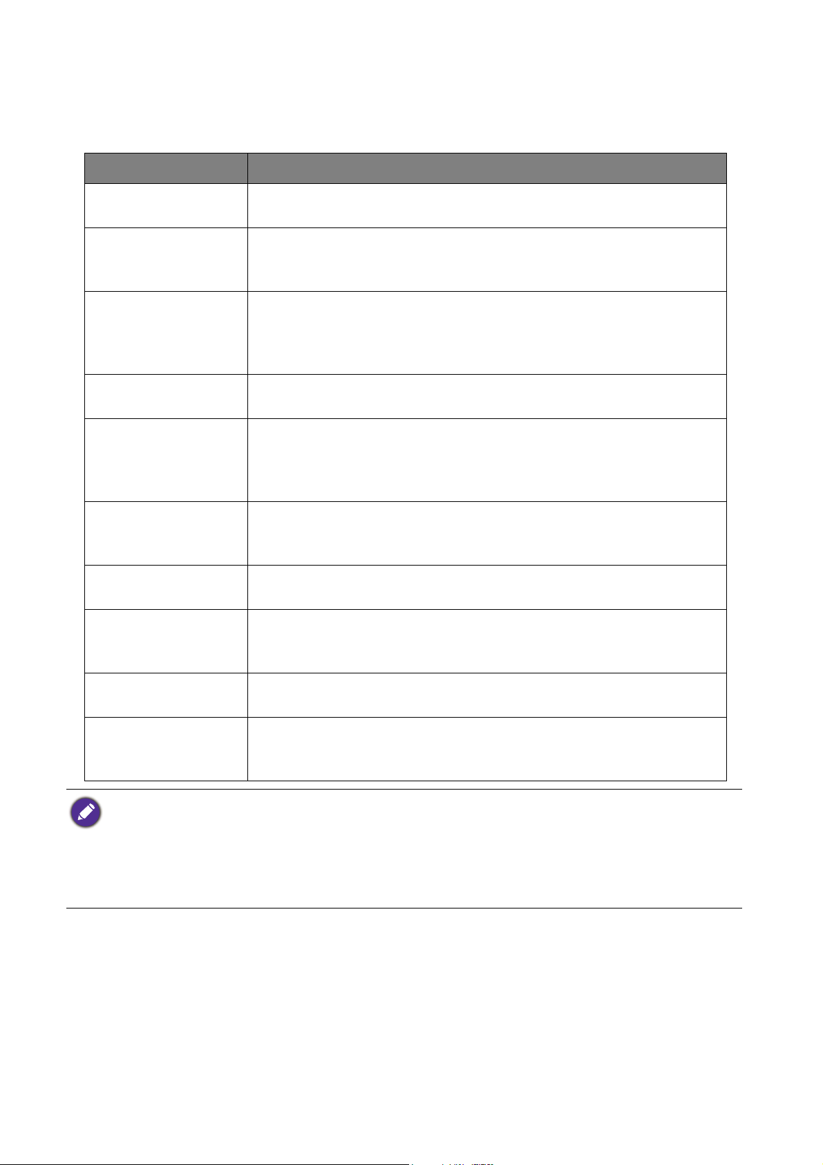
Product features
The product is equipped with the following features:
Features Description
True Plug & Play
No Software
Split Screen
Presentations
Auto Channel
Selection
Touch Back
Screen Casting for
Mobile Devices
Wireless 802.11ac/n
Simply connect the product into your USB and HDMI ports, then
push the button to start presenting immediately.
The product doesn't need any software installation or execution.
There's no setup, configuration, or waiting for pop-ups to launch. Just
plug into your PC or Mac and start presenting immediately.
Up to four users can simultaneously project their screen via the
product in a dual-screen, 3-way or 4-way split screen configuration, so
that you can view and reference multiple documents/videos at the
same time during your presentation.
The product automatically selects the best wireless channel upon
boot-up, ensuring smooth presentations in any environment.
When the Host is connected to a touchscreen display via its USB
ports, you can use the touchscreen to control the screen of the PC
that is presenting, allowing you to actively engage with the content
that is being presented.
Project your mobile device’s screen wirelessly by connecting your
mobile device to the Host via the InstaShare app or screencasting
capabilities of your mobile device.
The latest 802.11ac/n Wi-Fi guarantees extremely smooth wireless
streaming without lag or buffering.
The product's HDMI output supports up to 60Hz Full HD 1080p
Video and Audio
video and stereo sound without cable clutter or complicated driver
selection.
Assured Performance
Peace of mind for consistent wireless presentation performance
without relying on your PC.
Keep your presenter view, notes, and backup data on your laptop
Extended Desktop
screen while presenting to the wireless screen with extended desktop
in both Windows and OS X.
• Touch back via USB port is only supported for Windows-based PCs. Macs and mobile devices cannot be
controlled via touch screens.
• Transmission distance depends on actual environment. Stated distance is based on line-of-sight measurement.
Structures constructed of steel, wood, concrete, or brick may decrease transmission distance.
• According to regulatory restrictions in different regions of the world, Wi-Fi channels cannot be used in
countries outside the purchased region.
6 Introduction
Page 7
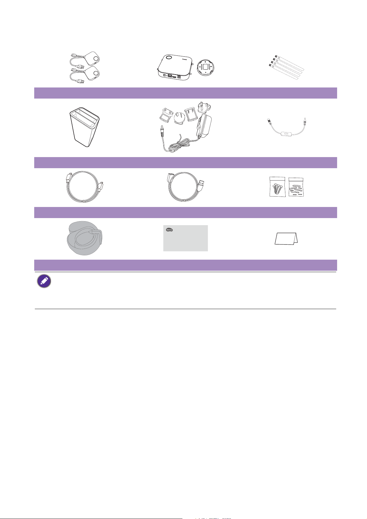
Package content
Quick Start Guide
LOCK
OPEN
InstaShow™ S Buttons InstaShow™ S Host and Lid 4 Antennas
Cradle Adapter & Plugs Extender Power Cable
Cable: HDMI A(M) to A(M) Cable: USB A(F) to USB A(M) Screws & Rubber Foot
Vel cro Str ap Quick Start Guide Safety Statement
• Available accessories and the pictures shown here may differ from the actual contents and the product
supplied for your region.
• Use original accessories to ensure compatibility.
• Always keep the product and accessories out of reach of children.
7 Introduction
Page 8

Product specification
Feature
Color Black
Video outputs HDMI 1.4, comply with HDCP
Frame Rate Up to 60fps depending on environment
Output resolution
Input resolution
Number of simultaneous connections 32 pcs
Audio Stereo, Radio quality 16bits 48KHz
Wireless transmission protocol
Data rate wireless Up to 867 + 300Mbps
Frequency Band 2.4GHz, 5GHz
Authentication protocol WPA2 (WPAS-PSK (Pre-Shared key) / WPA2-Enterprise)
Security (encryption) AES 128 bit
Support platform Windows, MAC, Chrome. Any OS supporting HDMI standard 1.4
Reach Max. 15M between the Button and the Host
Temperature range
Humidity
720x480, 720x576, 1280x720, 1920x1080, up to 3840x2160
(30Hz)
Video: 480p, 576p, 720p, 1080p
PC Timing: 640x480, 800x600, 1024x768, 1280x720, 1920x1080
IEEE 802.11ac, 5GHz, 2T2R
IEEE 802.11n, 2.4GHz, 2T2R
Operating: 0°C to +40°C (+32°F to +104°F)
Storage: -10°C to +60°C (+14°F to +140°F)
Storage: 5% to 90% relative humidity, non-condensing
Operation: 10% to 80% relative humidity, non-condensing
InstaShow™ S Button
Cable USB Type A, HDMI Cable Power supply DC 5V±10%, 0.5A
Reset button x1 Power consumption Normal: 2.5W
Split screen key x1 Dimension
Red (error)
LED
InstaShow™ S Host
Standby button x1 Power supply DC 12V±10%, 2A
Pairing key x1
Video output x1 HDMI 1.4 (video and audio)
DC Power Jack x1
LED
Cradle
Dimension 100.4x92.6x152mm Weight 550g
Green (Wi-Fi connected)
Blue (presenting)
Red (error)
Green (ready for connection)
Blue (presenting)
Weight 81g
Power consumption Normal: 24WWAN x1
Dimension (WxHxD)
(not including rubber feet)
Weight (include antenna) 330g
With cable: 81x291x24.2mm
Without cable: 67x67x24.2mm
With antennas: 200x150x140mm
Without antennas: 154x34x140mm
8 Introduction
Page 9

Overview
4
3
1
2
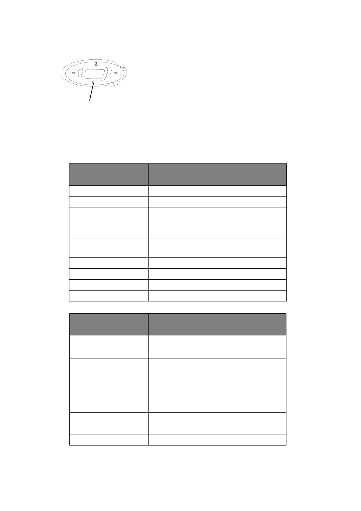
Bottom of a Button
5
8
6 5 4 32
1
1
1
1
7
Button
1. Present key with LED indicator
Press to start or stop presenting.
2. Split screen key
Press to enable split screen presentations.
3.
USB 3.0 connector
Connect to a computer or laptop.
4. HDMI 1.4 connector
Connect to a computer or laptop.
5. RESET
Poke the RESET hole to reset the device if the
device stops responding. Refer to Resetting a Host
on page 25 for more information.
Host
1. Fixture parts for the Antennas
Refer to Assembling the Host on page 12 for more
information.
2. USB-A Ports
Connect to a touchscreen display, mouse, or
keyboard, to control the projected screen.
3. HDMI port
Connect to a display using a Cable HDMI A(M) to
A(M).
4. LAN port
Allows users access to the web management
interface through a direct or network connection.
5. RESET
Poke the RESET hole to reset the device if the
device stops responding. Refer to Resetting a
Button on page 26 for more information.
6. DC 2A port
Connect to the supplied adapter extender power
cable and adapter to power the Host.
7. PAIRING key
Press to pair with a Button.
8. Standby button with LED indicator
Press to turn the Host on and off.
9 Introduction
Page 10
9. Lid
Alignment hole
Lid of the Host
9
Refer to Attaching the Host to the ceiling on page
12 for more information.
LED indicators of the Button and the Host
Please refer to the tables below for detailed indicator and status descriptions for the Button and the
Host.
LED indicator on the
Button
Status Description
Static blue The device is presenting.
Flashing blue The device is in the process of pairing
• The device is starting up and connecting to
Flashing green
the host.
• The device is upgrading the firmware.
Static green
The device is connected and working
normally.
Flashing red The device is unable to connect to a host.
Off The device is powered off.
Static red The device is resetting.
Quick flashing red The reset process is triggered.
LED indicator on the
Host
Status Description
Static blue Connected device is presenting.
10 Introduction
Flashing blue
The device is in the process of pairing.
• The device is starting up.
Flashing green
• The device is upgrading the firmware.
50% static green The device is in network standby mode.
Static green The device is on and ready for connection.
Flashing red The device is encountering a problem.
Static red The device is resetting.
Off The device is powered off.
Quick flashing red The reset process is triggered.
Page 11

Installation
This section will guide you on how to prepare the unit before its initial use.
Environment check
Before installing your InstaShow™ S kit, check the environmental conditions.
1. Do not install the device near heat sources like radiators or direct sunlight, or in a site with
excessive dust or humidity.
2. Ambient temperature conditions are listed as below. Maximum ambient temperature should be
+40°C or 104°F. Minimum ambient temperature should be +0°C or 32°F. Storage temperature
should be -10°C to +60°C (14°F to 140°F).
3. Humidity conditions are listed as below. For storage, the relative humidity should be 5% to 90%
(non-condensing). For operation, the relative humidity should be10% to 80% (non-condensing).
As the product works with different displays, the steps required to complete the installation may vary
according to the actual environment and your display specifications. Follow the procedures below
and refer to the specified sections for details.
1. Assemble the Host with the antennas. See Assembling the Host on page 12 for details.
2. Connect the Host to the display and power properly. See Connecting the HDMI cable and
power on page 17 for details. Four installation methods are provided.
• Attaching the Host to the ceiling
• Attaching the Host to a ceiling mount
• Placing the Host on a table
• Installing the Host on the wall or trolley
3. Connect the Buttons to the desired devices and power properly. See Setting up and powering a
Button on page 20 for details.
4. Make sure that all the connected devices have been powered on. Press the source button of the
display and make sure that the HDMI source has been transmitted. See Pairing a Button and
Host on page 23 for details.
11 Installation
Page 12
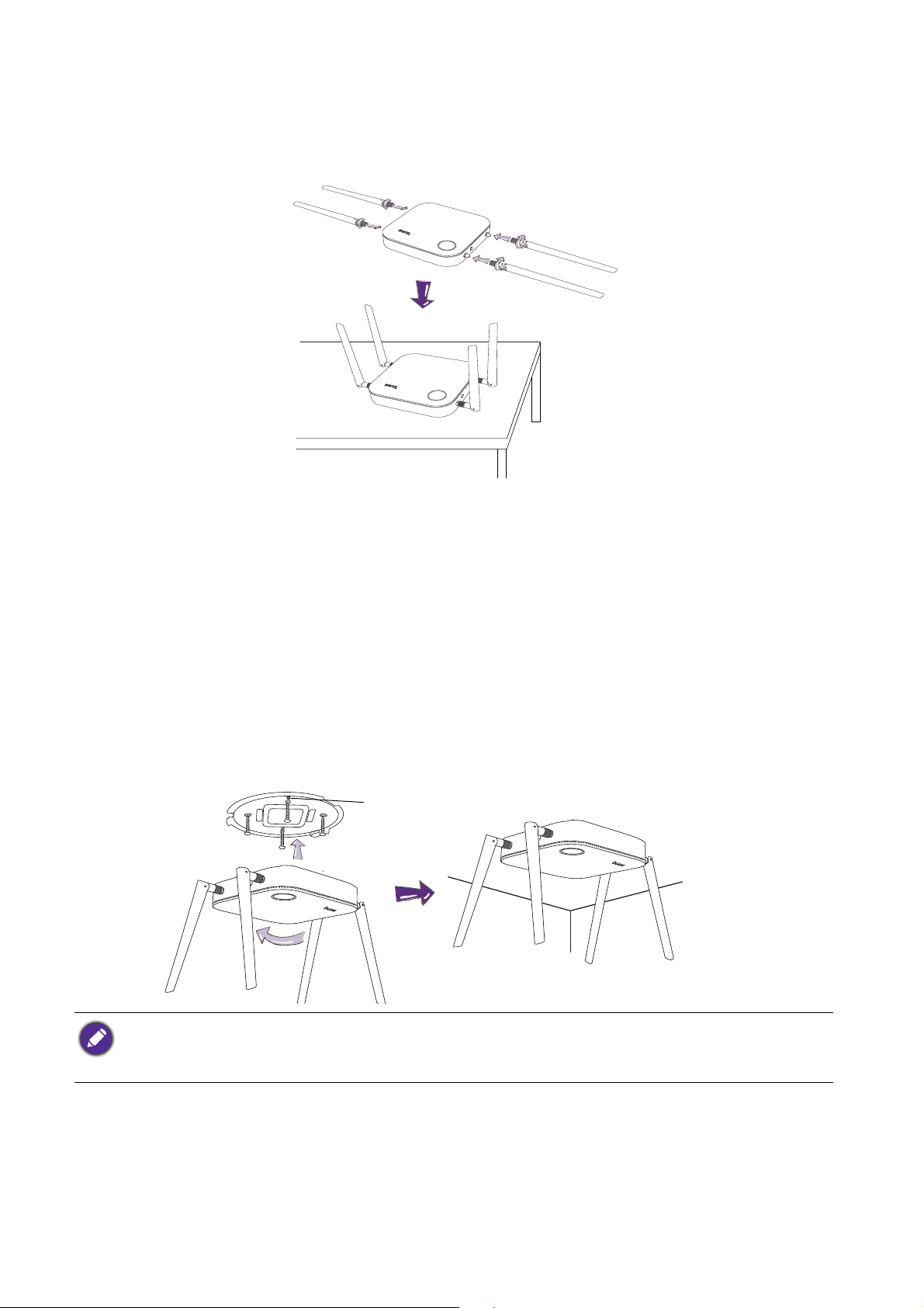
Assembling the Host
1
2
34
Alignment hole
Assemble the Host with four antennas by turning the antennas clockwise (right) and
counterclockwise (left) to fasten them tightly.
Setting up the Host
You are provided with four different ways to position the Host. The total weight of the Host Unit is
330g.
Attaching the Host to the ceiling
1. Place the lid on the ceiling and locate the alignment hole.
2. Use the screws provided to lock the lid to the ceiling.
3. Lock the first hole (1).
4. Follow the instruction in the illustration below to lock the other holes (2-4).
5. Rotate the Host counterclockwise to affix the Host to the lid.
• Please only use the screws (M3*16 tapping screw) provided with the kit to mount the Host to the ceiling.
• Please see Positioning the Host antennas on page 16 for guidelines on positioning the antenna to maximize
signal reception.
12 Installation
Page 13
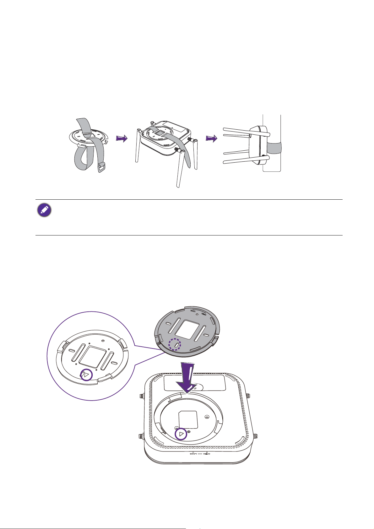
Attaching the Host to a ceiling mount
If the display is mounted on the ceiling:
1. Attach the Host to the ceiling mount using the provided velcro strap.
2. Fix the Host to the mounting holder.
3. Use the supplied velcro to fix the mounting holder and the Host to the ceiling mount as shown
in the illustration.
• Please only use the velcro strap (300(L)mm*25(W)mm) provided with the kit to mount the Host to a ceiling
mount.
• Please see Positioning the Host antennas on page 16 for guidelines on positioning the antenna to maximize
signal reception.
Placing the Host on a table
If your display is placed on a table, first attach the lid of to the Host in the following the process
described below:
1. Align the lid over the bottom of Host so that the triangle on the bottom side of the lid is aligned
to the triangle in the lid compartment, then insert the lid into the lid compartment.
13 Installation
Page 14
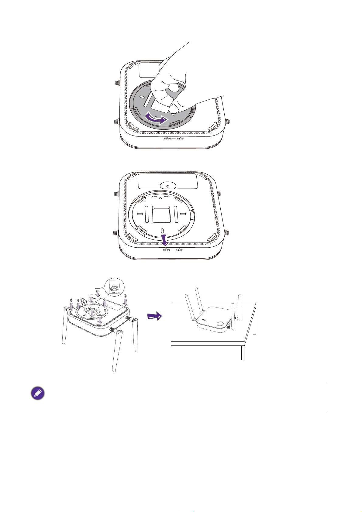
2. Turn the lid counter-clockwise until it clicks into place.
3. When the lid is correctly installed on the Host the alignment hole on the lid should be pointed
to the LOCK print at the front side of the Host.
4. Attach the rubber feet to the recesses on the lid and put the Host right next to the display.
• Please only use the rubber foot provided with the kit to attach to the Host.
• Please see Positioning the Host antennas on page 16 for guidelines on positioning the antenna to maximize
signal reception.
14 Installation
Page 15
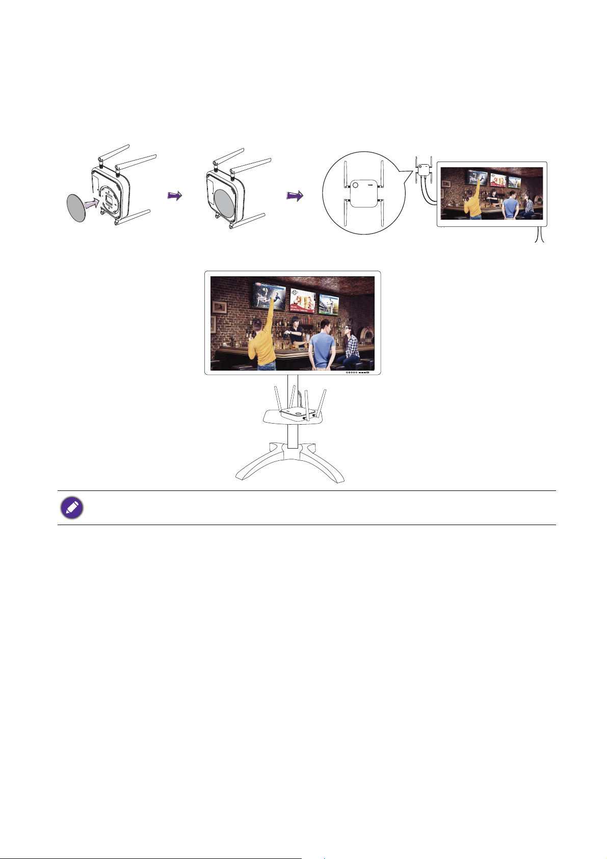
Installing the Host on the wall or trolley
If you need to install the Host near a display:
1. Stick double-sided tape to the lid of the Host.
2. Affix the Host on the wall near the display.
3. Keep the antennas away from any signal obstructions.
You can also place the Host on a mobile display trolley. See the illustration.
• Please only use double-sided sponge tape on the lid of the Host.
• Please wait 24 hours after you attach the double-sided sponge tape to the lid of the Host.
15 Installation
Page 16
Positioning the Host antennas
Once you have properly installed the Host, follow the guidelines below to position the antennas to
maximize signal reception:
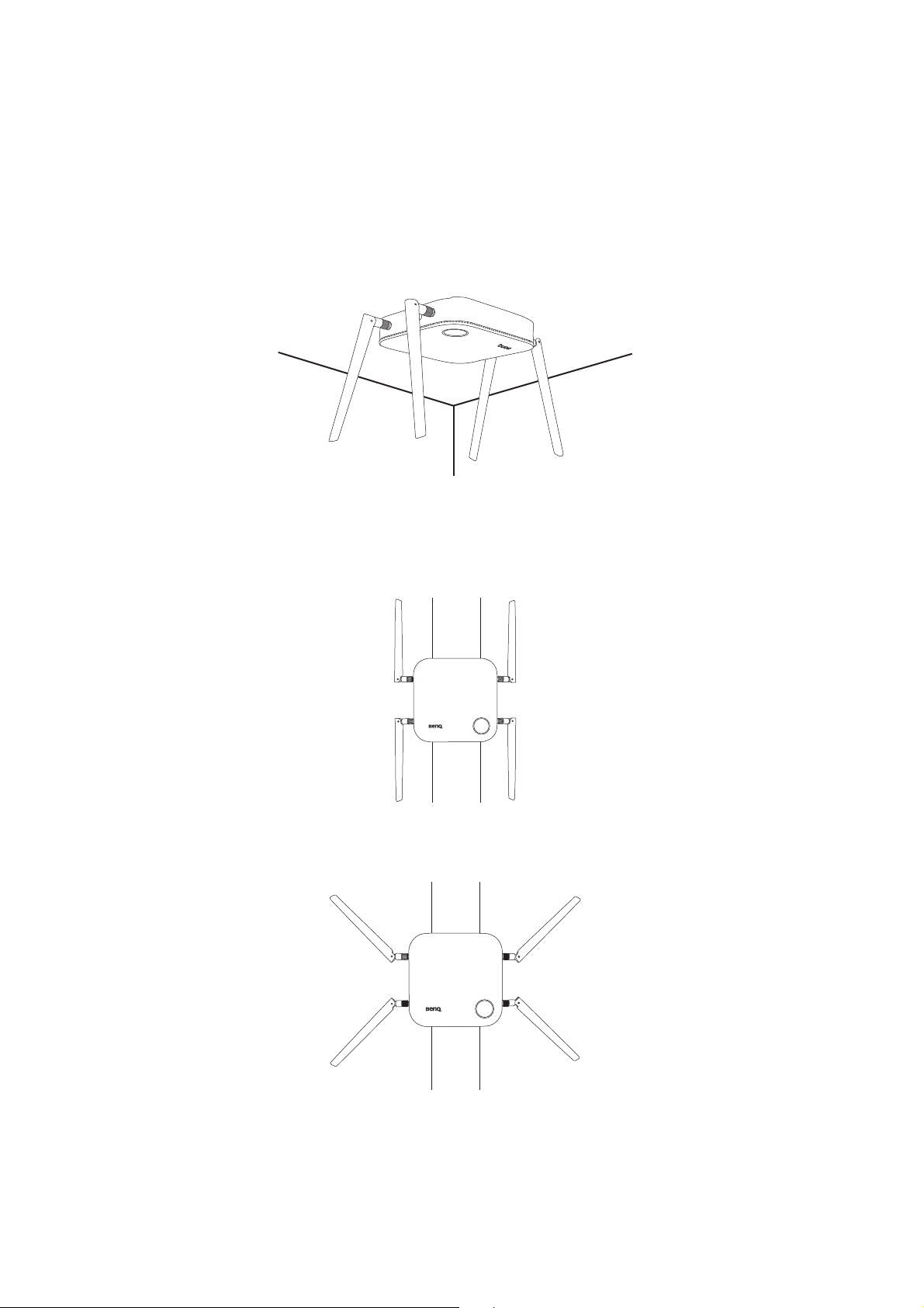
For ceiling installation
Position the antennas so that they are both pointed downwards at an angle roughly perpendicular to
the ceiling:
For ceiling mount installation
• Position the antennas so that they are both point either upwards or downwards roughly parallel to
the ceiling mount:
• If you encounter bad signal reception after initial use of the Host you can manually adjust the
antennas so that they tilt at a slight angle to maximize signal reception. When doing so, avoid tilting
the antennas toward the ceiling mount:
16 Installation
Page 17
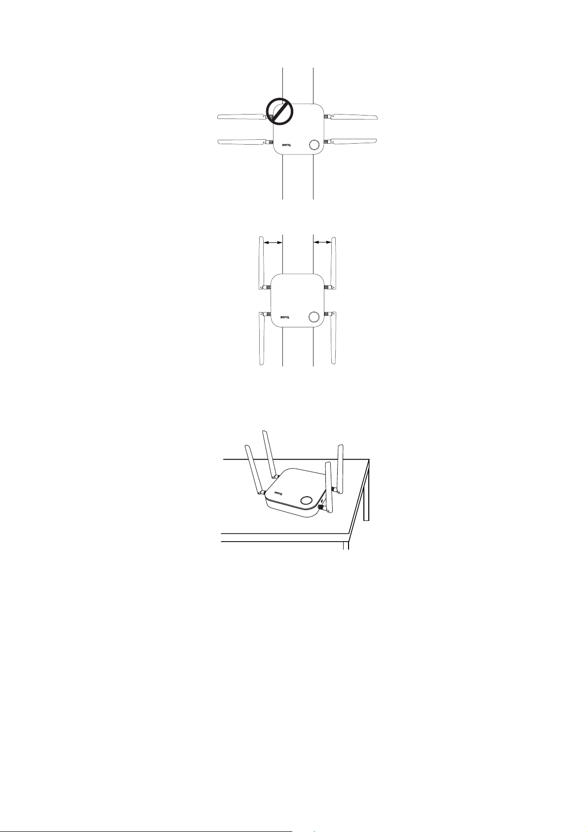
• Avoid positioning the antennas in a horizontal manner, this may result in a weak signal reception:
• If the Host is attached to a metallic ceiling mount ensure that the antennas are at least 3 cm away
from the metal portion of the ceiling mount:
3 cm
3 cm
For table placement
Position the antennas so that they are both pointed upwards roughly perpendicular to the table:
Connecting the HDMI cable and power
Once the Host has been positioned properly near the display, connect the HDMI cable and power to
ensure signal transmission.
17 Installation
Page 18
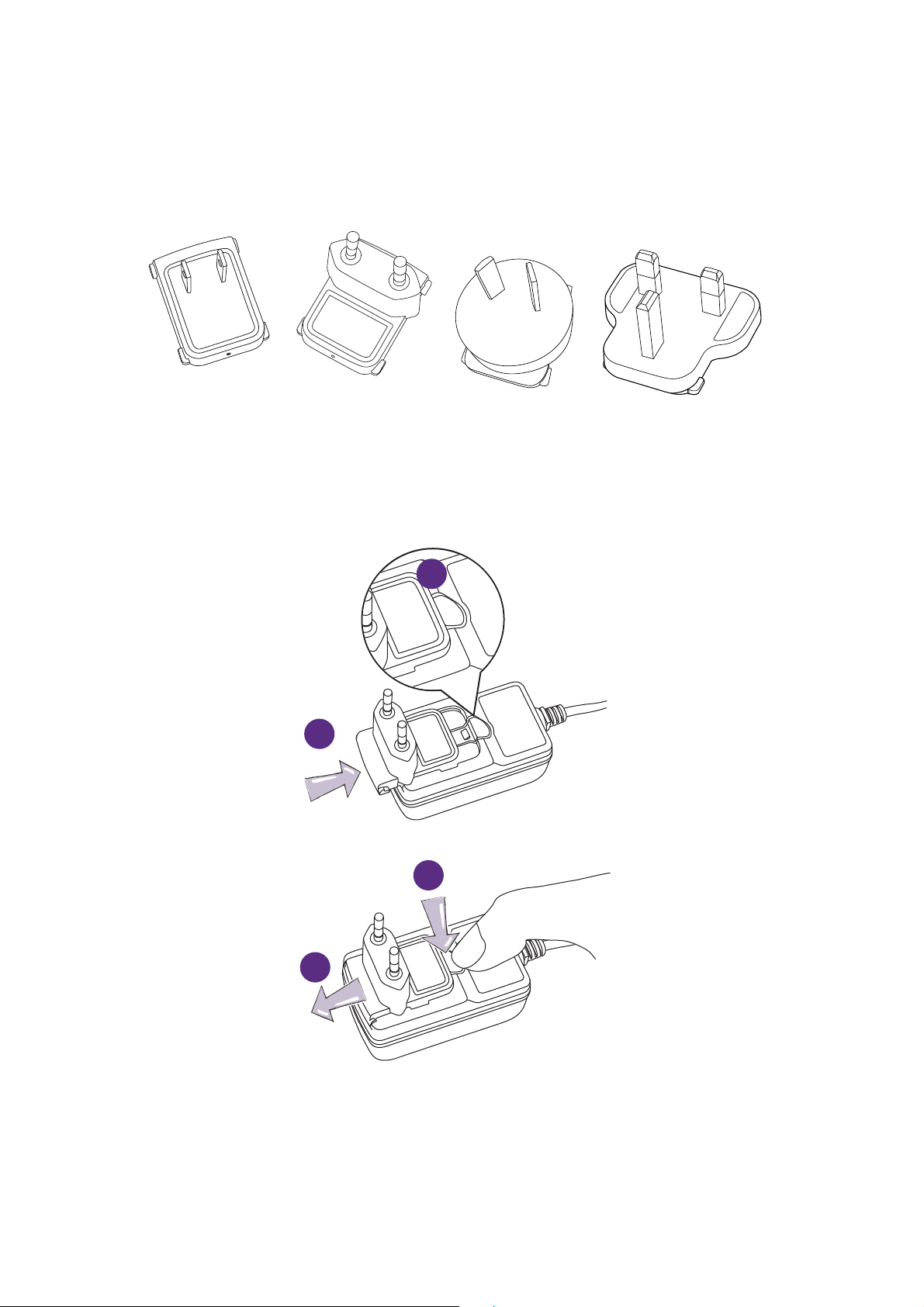
Assembling the adapter
Standard EuropeanStandard American Standard Australian Standard UK
1
2
Every adapter provided in the box includes a plug socket and plugs based on the region in which you
purchased the product. Below are images of the standard American, standard European, standard
Australian, and standard UK plugs:
To connect the plug of your choice, follow the steps below.
1. Align and insert the plug into the adapter.
2. Push the plug all the way in until it clips into place.
To disconnect the plug, follow the steps below.
1
2
1. Push the latch in the middle.
2. Detach the plug by pushing it outward and remove the plug.
18 Installation
Page 19
Connecting the HDMI cable
HDMI
HDMI
HDMI
POWER
HDMI
Connect the HDMI cable to the HDMI out jack of the Host and the HDMI input jack of the
projector.
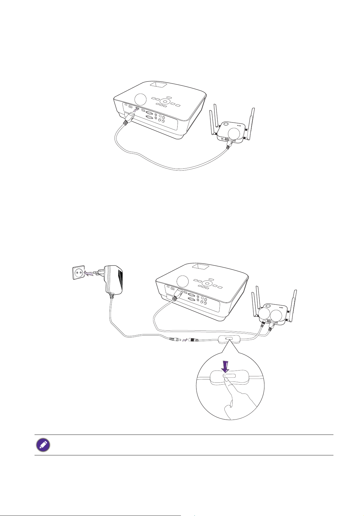
Power supply via a power adapter
Connect the male connector of the extender power cable to the power jack of the Host, then
connect the supplied power adapter to the female connector of the extender power cable, and then
plug the other end of the power adapter into a wall socket. Once the connection is set up press the
power switch on the extender power cable to supply power to the Host, the LED indicator on the
standby button of the Host lights up static green when the power is supplied.
For BenQ IFP (Interactive Flat Panel) products, please have power supplied via a power adapter.
19 Installation
Page 20
LAN connection
The Host can be connected to a local network or directly to a laptop. The LAN connection can be
used to configure your product and update the software. Insert a network cable with RJ-45
connectors into the LAN port and connect the other side to a LAN.
Setting up and powering a Button
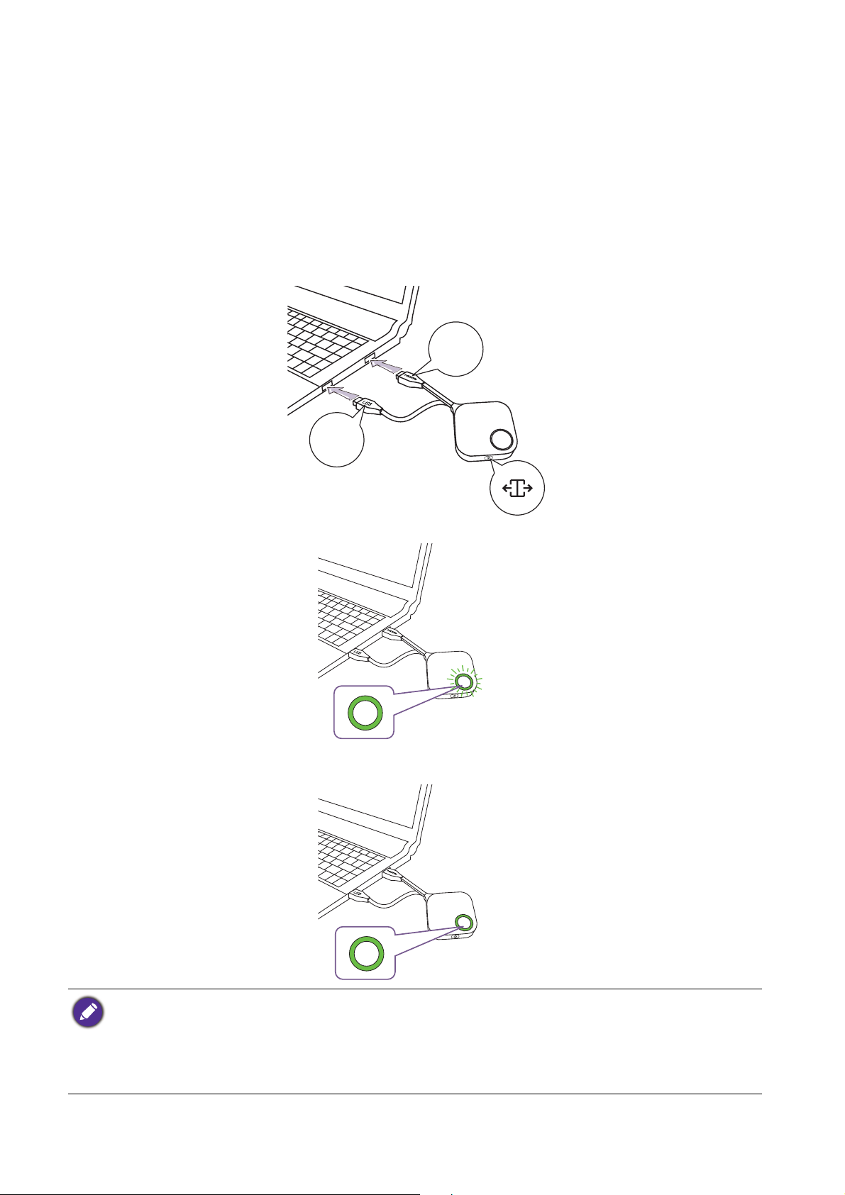
1. Connect the Button’s HDMI and USB jacks to the corresponding inputs of a laptop. See the illustration.
HDMI
1.4
USB
3.0
2. The LED indicator of the Button will flash green while the Button is starting up.
3. When the Button is ready to present, the LED indicator will turn solid green. Press the Present
key when the LED indicator turns green.
• If the Button encounters problems while pairing with the Host during startup the LED indicator will flash red.
Repeat the previous the process again until the LED turns solid green. See LED indicators of the Button and
the Host on page 10 for more information on LED behavior.
• Handle the Button cable with care. Rough handling might cause defects.
• Pull/Push the plug instead of the cable when inserting or removing Buttons.
20 Installation
Page 21
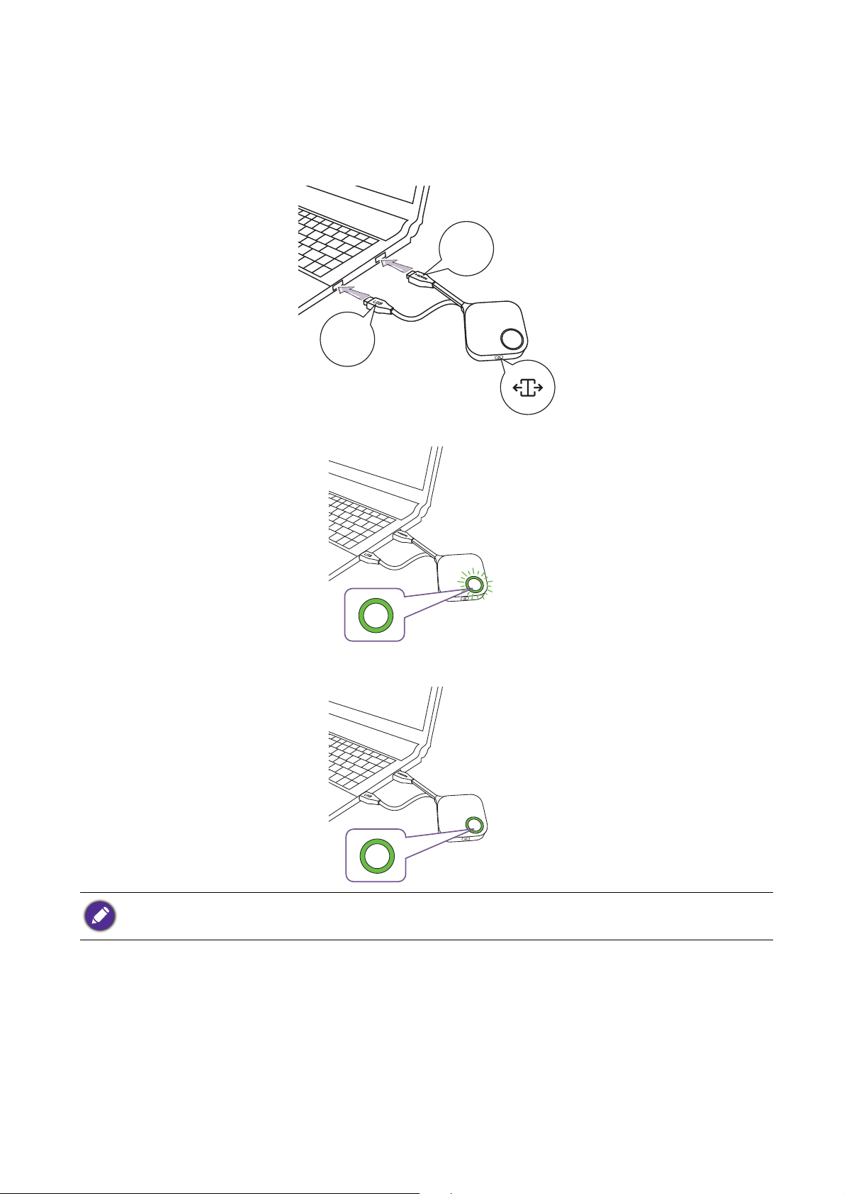
If you purchase an additional Button (via a Button Kit), please follow the process described below:
1. Follow the pairing instructions described in Pairing a Button and Host on page 23.
2. Connect the Button’s HDMI and USB jacks to the corresponding inputs of a laptop. See the
illustration.
HDMI
1.4
USB
3.0
3. The LED indicator of the Button will flash green while the Button is starting up.
4. When the Button is ready to present, the LED indicator will turn solid green. Press the Present
key when the LED indicator turns green.
• Handle the Button cable with care. Rough handling might cause defects.
• Pull/Push the plug instead of the cable when inserting or removing Buttons.
21 Installation
Page 22
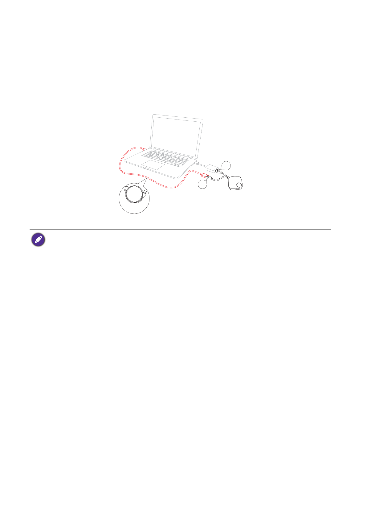
Using Cable USB A(F) to USB A(M)
A USB cable is provided for MacBook and Windows laptop users.
1. Insert the HDMI cable of the Button to the HDMI converter of your laptop.
2. Connect the cable USB A(F) to your laptop.
3. Connect the Button’s USB jack to the Cable USB A(M).
HDMI
USB
Cable USB A(F) to
USB A(M)
Make sure your own HDMI converter is workable.
22 Installation
Page 23

Pairing a Button and Host
USB
3.0
HDMI
1.4
A product set includes a Host and two Buttons, which are paired before shipment. In such a case,
you don’t need to pair them again. However, if you buy two or more product sets, and you want to
pair a Button with a different Host, you need to follow the instruction below. If you buy an additional
Button kit, and you want to pair the new Buttons with your Host, you need to follow the instruction
below as well.
When the Host is placed on a table
1. Make sure your Host is ready with power supply. Connect the Button’s HDMI and USB jacks to
the corresponding inputs of a laptop.
2. When the new Button is connected to the laptop, the LED indicator of the Button will flash red.
The Button is in pairing mode, waiting to pair with your Host.
If a Button nearby has been paired with a Host before, it will turn static green.
23 Installation
Page 24

3. Press the PAIRING key of the Host for five seconds, the LED indicator of the Host will blink
00:00:00
00:00:05
00:00:00
00:00:05
blue for two minutes, waiting to pair with a Button.
If the Host is attached to the ceiling so that it is not easy to press the PAI RI NG key, please use the pairing
process in the web management interface. Refer to Pairing on page 48 for information.
4. Press the split screen key on the side of the Button for five seconds. The LED indicator of the
Button will blink blue for about 10 seconds. The pairing process is ongoing. The “Pairing in
progress” message will be shown on the screen.
24 Installation
Pairing in progress
The images are for reference only. Each product has different serial number.
Page 25

5. The LED indicator of the Button turns static green and a “Pairing complete” message will be
Pairing complete
1
2
shown when the Host and Button are successfully paired.
The maximum number of Buttons you can pair with one Host is 32.
Storing Buttons and USB cable in the cradle
You are provided with two different ways to store the Buttons in the cradle. Place the Buttons in the
cradle vertically (1) or horizontally (2). See the illustrations.
Resetting a Host
Resetting a Host allows you to return the Host to its original factory settings. You may want to reset
the Host because of either one of the following reasons:
• You want to clear the web management interface of all changes made to its configurations, such as
pairing information, passwords, SSID, Frame Rate, etc. and return it back to its default settings.
Refer to Web management on page 34 for more information.
• You are unable to access the web management interface (for instance due to an altered or lost
password).
25 Installation
Page 26

Reset the Host using the following steps:
1. Connect the power port on the Host to a power source and wait for at least 90 seconds.
After the Host has been connected to a power source for at least 90 seconds, the Host LED may indicate any one
of the statuses described in LED indicators of the Button and the Host. As long as the Host
to a power source for at least 90 seconds, you may proceed to the next step of the resetting process regardless
of the status of the Host
LED.
has been connected
2. Poke the RESET hole at the rear of the Host with a pin for at least 5 seconds.
3. The Host LED will begin quick flashing red (flash red twice every second) for 10 seconds, then
light up static white for 3 seconds, indicating that the Host is resetting.
4. Once the Host LED lights up static green the resetting process is complete.
Do not disconnect the Host from its power source at any time during the resetting process.
Resetting a Button
Resetting a Button allows you to return the Button to its original factory settings. You may want to
reset a Button because of either one of the following conditions:
• You purchased an additional Button (via a Button Kit) which has not been paired to a Host.
• A Button that was included in the original package has been paired to a different Host (one which
was not originally included with the Button in the package), and you want to quickly pair it back to
its original Host.
• A Button that was included in the original package has been paired to a different Host (one which
was not originally included with the Button in the package), and you want to re-pair the Button to
its original Host while the Host is not powered on.
Reset a Button using the following steps:
1. If the original Host is powered on, place the Button within range of the original Host and ensure
the LED on the Host is static green.
26 Installation
Page 27

2. Connect the USB 3.0 connector on the Button to a powered on laptop and wait for at least 30
seconds.
After the Button has been connected to a powered on laptop for at least 30 seconds, the Button LED may
indicate any one of the statuses described in LED indicators of the Button and the Host. As long as the Button
been connected to a powered on laptop for at least 30 seconds, you may proceed to the next step of the
resetting process regardless of the status of the Button
LED.
has
3. Poke the RESET hole at the bottom of the Button with a pin for at least 5 seconds.
4. The Button LED will begin quick flashing red (flash red twice every second) for 10 seconds, then
light up static white for 2 seconds, indicating that the Button is resetting.
5. Once the Button LED lights up static green the resetting process is complete.
Do not disconnect the Button from its power source at any time during the resetting process.
27 Installation
Page 28

Starting and stopping presentations
This section will guide you on how to start and stop a presentation using the product.
Getting ready
Make sure that all the connected devices have been powered on and ready for the presentation.
As the product could work with different projectors, IFPs, TVs, or monitors with standard HDMI
ports, the steps required to start a presentation may vary according to the actual environment and
your display specifications. Follow the procedures below and refer to the specified sections for
details.
1. To start a presentation, see Starting presentation on page 28 for details.
2. To stop a presentation, see Idle presentation on page 29 for details.
3. To start a split-screen presentation, see Split screen presentations on page 30 for details.
4. To start a presentation with a mobile device, see Presenting with mobile devices on page 31 for
details.
5. To control presentations via a touchscreen displays or mouse/keyboard see Touch back on page
33 for details.
Starting presentation
1. Make sure power is supplied to the Host. See Connecting the HDMI cable and power on page 17
for more information.
2. Choose the HDMI source corresponding to the Host on the display. You will see the Guide
screen.
Guide
Screen
3. Please follow the instruction on the Guide screen to supply power to the Button. You can also
see Setting up and powering a Button on page 20 for more information. The LED indicator on
the Button is static green when the Button is connected and working properly.
4. To start a presentation, press the Present key.
28 Starting and stopping presentations
Page 29

5. The device starts presenting, and the LED indicator of the Button turns static blue.
Present
key
Present
key
• Make sure the transmission distance between the Button and Host is within 15M and with no obstacles.
• The product supports MacBooks and Windows laptops to mirror an extended desktop.
Idle presentation
1. To stop a presentation, press the Present key.
2. The device stops presenting, and the LED indicator of the Button turns green.
3. Users can press the Present key to return to the presentation.
29 Starting and stopping presentations
Page 30

Split screen presentations
The product allows up to 4 users to present simultaneously in a split screen orientation.
Starting a split screen presentation
1. Connect a Button to each computer that will be presenting in the split screen presentation. See
Setting up and powering a Button on page 20 for more information.
Make sure that all Buttons have already been paired to the Host projecting the presentation. See Pairing a Button
and Host on page 23 for more information.
2. Start a normal presentation using one of the Host buttons. See Starting presentation on page 28
for more information.
3. Press the split screen button on the Host that started the presentation to enable split screen
presentations.
4. Once a notification appears on-screen indicating that the split screen function has been enabled,
press the Present key on the Button of the second computer that wants to join the split screen
presentation.
5. Repeat step 4 for all other users that want to join the split screen presentation.
• Only up to 4 users are simultaneously supported in a split screen presentation.
• The layout of the split screen presentation will be dictated by the amount of users in the presentation.
• If split screen is not enabled by the initial Button, all subsequent connections by other Buttons will be full
screen presentations.
30 Starting and stopping presentations
Page 31

Switching from a split screen to a full screen presentation
Once in a split screen presentation you can switch to a full screen presentation of any of the
participant’s screen by pressing the split screen button on the Button of the computer that wants to
present in a full screen.
To return to a split screen presentation repeat the steps in Starting a split screen presentation on
page 30.
Presenting with mobile devices
Users with mobile devices can connect their mobile devices to the Host and make a presentation via
the InstaShare app by following the steps below:
1. Install the InstaShare app on your mobile device using the QR code located on the guide screen.
2. The name of the Host is displayed on your mobile device’s Wi-Fi menu, select it to make a Wi-Fi
connection. No password is required.
31 Starting and stopping presentations
Page 32

3. Select a desired function and follow the on-screen instructions to project.
InstaShare
Functions and interface of the app may be updated without prior notice
32 Starting and stopping presentations
Page 33

Touch back
USB 2
USB 1
WAN
RESET HDMI
When a Host is connected to a touchscreen display and a PC is presenting via a Button, you can use
a USB Type-A cable to connect any of the USB ports located at the rear of the Host to the touch
input USB port of the display to control the interface of the PC remotely via touch gestures on the
display.
The product only supports touch back for Windows-based PCs. It does not support touch back for MacBooks or
smartphones connected via the InstaShare app.
For presentations that do not feature a touchscreen display, you can connect a USB mouse and/or
USB keyboard to any of the USB ports located at the rear of the Host to control the interface of the
presenting computer and input text remotely via the mouse/keyboard.
RESET HDMI
WAN
USB 1
USB 2
33 Starting and stopping presentations
Page 34

Web management
The product is equipped with a web management interface that enables you to configure its features
through a browser such as Google Chrome (version 49.0.26), Internet Explorer (version 8.0), or
Firefox (version 46.0.1).
The features may vary according to different firmware versions.
Accessing the web management interface
Logging into the web management interface via direct connection
1. Connect your Host directly to a laptop using a network cable (RJ-45) and to a power source using
the power adapter.
2. Wait until the LED indicator on your Host lights up static green.
34 Web management
Page 35

3. The default IP address of your Host is 192.168.20.1. Change your laptop's IP address to
192.168.20.x (e.g. 192.168.20.100).
4. On your browser, enter the IP address: 192.168.20.1. On the login page, enter the default user
name (admin) and password (0000).
5. You will successfully log into the web management interface.
35 Web management
Page 36

Logging into the web management interface via LAN
If your Host is connected to your LAN, you can enter the IP Address shown on the screen via a web
browser.
Logging into the web management interface via a wireless network
The product supports 802.11 ac/n. It is compatible with most devices with Wi-Fi capability (e.g.
laptop or mobile devices), you can locate the Host via the WDC20_xxxxxx SSID (shown in the
Guide/Idle screen) in your laptop or mobile device’s wireless network menu and connect to it. The
default password is the same as the name of the SSID (for example, if the SSID is "WDC20_c7a3ae",
the password will be "WDC20_c7a3ae"). When the device is connected to the Host, enter the IP
Address, "192.168.168.2" in a web browser, then enter the user name and password as shown in step
4 of Logging into the web management interface via direct connection on page 34.
The following is an example of how you can log into the web management interface via a mobile
device with IEEE 802.11ac.
36 Web management
Page 37

1. Go to Settings > Wi-Fi, and you can find the SSID of your Host: WDC20_c7a3ae.
2. Enter the default password "WDC20_c7a3ae" and press Connect.
3. Access the web management interface following step 4-5 of Logging into the web management
interface via direct connection on page 34.
37 Web management
Page 38

Getting started
Function bar
Main column
Top command buttons
You can now use the web management interface to configure various settings of your Host.
Top command buttons
Change language
1. The default language is English. To change the interface language, go to the language settings panel
and you can see all available languages.
2. Click the language you want to switch to and your new language will be set.
3. Once a new language has been set both the web management interface and the product’s OSD
will feature the new language.
Supported languages vary by country/region where you purchase.
Logging out
Click Logout on the upper right corner.
Function bar
The function bar shows the settings menus available in the web management interface.
38 Web management
Page 39

Main column
The main column shows the detailed content from the function bar.
Information
Click Information and you will see detailed information for System Information, WAN,
Wireless Network, My Screen, and Screen Message.
You can change the Host Name under System Information.
39 Web management
Page 40

You can change the background image for the Host’s guide screen and/or idle screen by selecting
Tu to r i al B ox es
Guide Screen
Background Image
Tu to r i al B ox es
Idle Screen
Background Image
Custom in the Guide Screen or Idle Screen fields, then clicking the Select Image button that
appears, and then navigating to and selecting the image file on your local folder you want as either the
Hosts Guide Screen or Idle Screen.
• To hide the tutorial boxes on either the Guide Screen or Idle Screen, check the Tu to r i a l H i d e box.
• To revert to the default Guide Screen or Idle Screen, select Original in the respective screen’s field.
40 Web management
Page 41

You can enter messages under Screen Message. After filling in a message, press Apply to proceed.
Your message will be shown at the top of the Guide/Idle Screen.
For Screen Message, the maximum lines allowed is 1 line, and the maximum number of characters allowed per
line is 100 characters (alphanumeric or Chinese).
WAN
Click WAN and you will see the default WAN IP Address of the Host. The default connection
type is DHCP which acquires the IP Address from your DHCP server of your network. If you want
to change your WAN IP Address, choose Static IP under WAN Connection Type. Press
Apply after changing the WAN IP Address.
41 Web management
Page 42

Wireless Network
Click Wireless Network and you will see the Setting, Wi-Fi Radio Setup, and Wireless
Nodes Status menu for the Host.
Setting
The Wi-Fi SSID for the Host is displayed in the SSID field. The SSID for the Host is based on the
Host Name set in the Information > System Information menu, to change the SSID for the
Host use the Host Name field in the System Information menu.
42 Web management
Page 43

Wi-Fi Security Option provides the user WPA2 Personal and WPA2 Personal Mixed
security options for the Host’s wireless connection when users access the web management
interface via a wireless network.
WPA2 Personal allows only users with Advanced Encryption Standard (AES) encryption to
connect to the Host.
WPA2 Personal Mixed allows users with various encryption methods to connect to the Host,
which may be needed for users with older wireless devices.
The Wi-Fi security options described above only applies to the Wi-Fi connection used to access the web
management interface via a wireless network. The Wi-Fi connection used for data transfer between the Host and
Buttons utilizes a fixed WPA2-PSK security setting which cannot be changed.
Isolate is a security setting that allows you to isolate all Wi-Fi connections to the Host, so that
devices that are connected to the Host via a Wi-Fi connection are isolated and cannot access any of
the other devices connected to the Host for possible hacking. The default setting for this field is
Enable. To deactivate the isolation setting and allow Wi-Fi devices connected to the Host to access
each other select Disable.:
43 Web management
Page 44

You can choose the available frequencies for the Host’s Wi-Fi signal in the 2.4G Enable and 5G
Enable fields. A 2.4G Wi-Fi signal is a signal that features a larger coverage range but slower data
speeds and is more commonly used by older mobile devices, while a 5G Wi-Fi signal features faster
data speeds at a smaller range. To enable or disable either 2.4G or 5G Wi-Fi signals by selecting
Enable or Disable in the 2.4G Enable and/or 5G Enable fields.
• Certain mobile devices are unable to access 5G Wi-Fi signals due to hardware limitations. If your mobile device
is unable to connect to the Host via Wi-Fi, select Enable in the 2.4G Enable field.
• Both 2.4G Enable and 5G Enable can be enabled at the same time.
After you configure all the Wireless Network > Setting items, press Apply to proceed.
Wi-Fi Radio Setup
In the Tr an sm iss io n Pow er field you can set the strength of the Wi-Fi signal with the available
options being of Heavy for a strong Wi-Fi signal (20 dbm for 2.4G; 15 dbm for 5G), Standard for a
standard Wi-Fi signal (18 dbm for 2.4G; 12 dbm for 5G), and ECO (15 dbm for 2.4G; 10 dbm for 5G)
for a weaker, energy saving signal.
44 Web management
Page 45

In the 2.4G Channel and 5G Channel fields you can configure the Host to automatically select the
wireless channel with the best performance for either signal during the initial setup of the Host by
selecting Auto, or you can select a wireless channel manually. The default 2.4G Channel and 5G
Channel setting for the Host is Auto.
45 Web management
Page 46

In the 2.4G Channel Width and 5G Channel Width fields you can configure the channel width
for your 2.4G and/or 5G Wi-Fi signal. The available options for 2.4G Channel Width are 20MHz
and 40MHz, while the available options for 5G Channel Width are 20MHz, 40MHz, and
80MHz. The default channel width for 2.4G Channel is 20MHz while the default channel width for
5G Channel is 40MHz.
The supported wireless channels listed vary according to wireless regulations of the country/region which is listed
in the Wi-Fi Area field.
In 5G Mode, you can select the Wi-Fi standard for the 5G Wi-Fi signal. The available options are N
Only and AC Only. The default 5G Mode setting is N Only.
The Wi-Fi standard for the 2.4G Wi-Fi signal in the 2.4G Mode field is set to N Only and cannot be configured.
46 Web management
Page 47

After you configure all the Wireless Network settings, press Apply to proceed.
Wireless Nodes Status
The Wireless Nodes Status sub-menu lists all the devices connected to the Host via Wi-Fi
indicates their MAC Address, Device Name, IP Address, Wi-Fi channel used (2.4G/5G), and
connection time (Uptime).
47 Web management
Page 48

Pairing
USB
3.0
HDMI
1.4
Click Pairing and you will see Pairing and Pairing Status.
Pairing is used when the Host is attached to the ceiling as it is not easy to press the PAIRING key
of the Host when the device is high on the ceiling. You can pair a Button and Host via the web
management interface.
1. Connect the Button’s HDMI and USB jacks to the corresponding ports of a laptop.
2. When the Button is successfully connected to the laptop, the LED indicator of the Button will
blink green.
3. Make sure the Host is properly connected to a power source.
4. Enable the 2.4G Wi-Fi channel in the Wi-Fi Radio Setup menu.
48 Web management
Page 49

5. Press Start pairing to pair the Host to the Button via the web management interface, you will
00:00:00
00:00:05
Pairing complete
have two minutes to pair with the Button.
6. Press the split screen key on the side of the Button for five seconds. The LED indicator of the
Button will blink blue for about 10 seconds. The pairing process is ongoing. A “Pairing in
progress” message will be shown on the screen.
Pairing in progress
7. The LED indicator of the Button will turn static green when the Host and Button are
successfully paired.
• Images are for reference only. Each product features a different serial number.
• The maximum number of Buttons you can pair with one Host is 32.
49 Web management
Page 50

8. You may press Stop pairing anytime to stop the pairing process.
50 Web management
Page 51

Advance Setting
Click Advance Setting to adjust Firewall, Host Output Resolution, Screen Scale, 4 Way
Split, Stream Encryption, Login Code, and HDCP Auto.
Firewall is a security setting that allows you to block/reject users from accessing the Host via its
WAN port in order to protect it from hacking. The default setting for this field is Reject which
enables the firewall and rejects access to the Host via its WAN port. To disable the firewall and allow
devices to access the Host via its WAN port select Accept.:
Users will still be able to access the web management interface via a direct connection to the WAN port when
the Firewall is set to Reject.
51 Web management
Page 52

Host Output Resolution configures the Host’s output resolution for video broadcast by the Host.
When Host Output Resolution mode is set to Auto the Host will select the output resolution
based on the connected display’s native timing, or you can select an output resolution manually.
Screen Scale allows users to adjust the borders of the Host’s video output so that it properly fits
the screen of the connected display. This setting is mainly intended for users who connect the Host
to a touchscreen display, so that the edges of the video align to the edges of the display’s screen to
ensure the accuracy of touch gestures. To adjust the Screen Scale setting, click the Adjustment
button, then use the toggle buttons to scale the video to fit the screen.
52 Web management
Page 53

4 Way Split enables or disables split screen presentations and has the same function as the split
screen button on a Button. See Split screen presentations on page 30 for more information split
screen presentations.
Stream Encryption is a security setting that allows you to select the level of encryption for the
connection between the Host and Buttons in order to protect it from hacking. The default setting for
this field is 3 Level, to change the setting to a lower level of encryption select 2 Level.
Login Code allows you to set a login password for connections by mobile devices which will appear
on the guide screen. The default setting for this field is Disable which means that no login password
is needed for mobile devices to connect to the Host. To set a custom login password for mobile
devices, select Custom and then enter the password you want in the field to the right of the Login
Code field. To set an automatically generated login password select Random.
53 Web management
Page 54

HDCP Auto is a security setting that allows you configure whether or not HDCP digital copy
protection is automatically enabled for the content output by the Host. The default setting for this
field is On, which means that HDCP copy protection will be automatically enabled by Host for
content that features HDCP copy protection and disabled for content that does not feature HDCP
copy protection. To change the setting so that HDCP copy protection is always enabled by Host
select Off.
After you configure all the Advance Setting items, press Apply to proceed.
If you want to restart the Host, click Restart and the Host will restart.
54 Web management
Page 55

If you want to place the Host in sleep mode, click Sleep.
To wake the Host from sleep mode, press the standby button on the top of the Host.
55 Web management
Page 56

Scheduling
You can change the schedule by clicking Scheduling. You can set System Time and Peri odi cal
Restart.
You can select your Time Zone and the NTP Server from which the time is obtained.
You can check Enable to set Periodical Restart. You can also set restart time and day.
After you configure all the Scheduling settings, press Apply to proceed.
56 Web management
Page 57

To o l
1
4
2
3
By clicking Tool, you can adjust Password Setup, Firmware Upgrade, Configuration
Management, Wi-Fi Traffic Test, and Log Setting.
Password Setup
You can change Password by:
1. Entering your old password.
2. Entering your new password.
3. Entering your new password again to confirm your new password.
4. Pressing Reset to proceed.
57 Web management
Page 58

Firmware Upgrade
The Firmware Upgrade sub-menu allows you to check for and execute firmware upgrades for
both the Host and Button.
• Checking for Upgrades (for Host)
Before checking for a new firmware upgrade for your Host, ensure that the Host is connected via the
WAN port to a router with access to the Internet, then click the New Firmware Check button to
check for a firmware upgrade. To have the Host periodically check for firmware upgrades check the
Periodical Check box.
Periodic checks for upgrades can only occur when the Host is connected via the WAN port to a router with
access to the Internet.
If a new firmware upgrade is available the new firmware version will be listed in the New Firmware
Ver sio n field.
58 Web management
Page 59

• Upgrading the Host’s Firmware
After checking for and confirming the availability of a new firmware upgrade you will be able to
upgrade your Host’s Firmware. The product allows you to upgrade the Host’s firmware using either
an OTA (Over The Air) upgrade or a direct upgrade from an upgrade file located on your local
computer.
To perform an OTA upgrade of the Host’s firmware, click the Firmware Upgrade button in the
New Firmware Version field.
To perform an OTA ensure that the Host is connected via the WAN port to a router with access to the Internet.
When performing any type of upgrade DO NOT do any of the following:
• Power off or press the reset button on the Host or Button.
• Close the browser window of the web management interface.
Failure to follow these warnings will result in firmware upgrade failure and subsequent product failure.
To perform a direct upgrade from an upgrade file located on your local computer follow the steps
below:
Before executing a direct firmware upgrade, please contact your BenQ regional office for access to the upgrade
files.
1. Click the Select File button in the Firmware File field.
2. Navigate to and select the firmware upgrade file.
59 Web management
Page 60

3. Click the Firmware Upgrade button in the Firmware File field.
When performing any type of upgrade DO NOT do any of the following:
• Power off or press the reset button on the Host or Button.
• Close the browser window of the web management interface.
Failure to follow these warnings will result in firmware upgrade failure and subsequent product failure.
• Upgrading the Button’s Firmware
You can upgrade the Button’s firmware using an upgrade file located on your local computer or
directly from your Host via the connection between the Button and Host.
To upgrade the Button’s firmware using an upgrade file located on your local computer follow the
steps below:
1. Select from a local file in the Firmware File field and then click the Select File button.
2. Navigate to and select the firmware upgrade file.
60 Web management
Page 61

3. Select the Button you want to upgrade and then click the Firmware Upgrade button in the
Upgrade selected InstaShow S button field.
When performing any type of upgrade DO NOT do any of the following:
• Power off or press the reset button on the Host or Button.
• Close the browser window of the web management interface.
Failure to follow these warnings will result in firmware upgrade failure and subsequent product failure.
To upgrade the Button’s firmware directly from your Host follow the steps below:
1. Select from RX in the Firmware File field.
2. Select the Button you want to upgrade and then click the Firmware Upgrade button in the
Upgrade selected InstaShow S button field.
When performing any type of upgrade DO NOT do any of the following:
• Power off or press the reset button on the Host or Button.
• Close the browser window of the web management interface.
Failure to follow these warnings will result in firmware upgrade failure and subsequent product failure.
61 Web management
Page 62

Configuration Management
Configuration backup files feature the configuration settings for your Host except for the host name,
SSID and wireless password settings, and pairing status. In Configuration Management, you can
choose Import Configuration File, Export Partial Configuration File, Export Complete
Configuration File, and Factory Default.
You can import configurations files by:
1. Clicking Import File to choose the file to import.
2. Navigating to and selecting the configuration file you want to import from your local computer.
You can export a partial configuration backup in the Export Partial Configuration File sub-menu
by:
1. Clicking Export.
2. Navigating to the folder you want to save the backup file to in your local computer and then
choosing Save.
3. The following set values will not be exported:
a. Information: Host Name
b. Wireless Network: SSID setting and password setting
c. Pairing: Pairing Status
62 Web management
Page 63

You can export a full configuration backup in the Export Complete Configuration File sub-menu
by:
1. Clicking Export.
2. Navigating to the folder you want to save the backup file to in your local computer and then
choosing Save.
The exported configuration file can only be imported by the same Host that exported the file. The configuration
file cannot be imported by any other Hosts.
You can have the Host restore to Factory Default by clicking Return to Factory Default
Setting.
When the process is confirmed the Host will begin restoring to Factory Default and the LED will
quick flash red (flash red twice every second) then restart. After the Host restarts the entire process
is complete.
Wi-Fi Traffic Test
The Wi-Fi Traffic Test sub-menu allow you to test the speed of the connection between your Host
and the Button.
To test the speed of the connection follow the steps below:
63 Web management
Page 64

1. Select the channel you want to test the speed of in the Option Channel field.
2. Click the Settings button to set the channel test.
64 Web management
Page 65

3. Click the Te s t button. The results of the test will be shown in the main window.
65 Web management
Page 66

Log Setting
Logs are records of all system activity for your Host, which may be used by support technicians to
track errors or locate bugs. In the Log Setting menu, download the system log to your local
computer by clicking Download To PC, clear the system log by clicking Clear Log, and view the
system log in the System Log View window.
Legal Announcement
For information about disclaimer or privacy policy, press Legal Announcement to find out more.
66 Web management
Page 67

Troubleshooting
Category Problem Cause Solution
Web Management >
Your screen is not
appearing on the
display when
pressing the Button.
The system is locked.
The Button is
connecting to
another Host.
Pressing time is not
enough.
Advanced Setting> Screen
Lock > Disable
The Button should be paired
again with the Host.
Press the Present key until the
LED indicator turns from green
to blue.
Yo ur s cre en
The screen turns
blank or flickers
when the Host is
presenting.
The screen lags
seriously and the
audio breaks up
sometimes.
Insufficient power
supply
Insufficient power
supply for the Button.
An laptop with USB
2.0 port may be used
as the power supply
for the Button.
Wi-Fi interference or
signal attenuation
Make sure the product’s power
is properly supplied or
connected.
• Make sure you use USB 3.0 as
the power supply for the
Button.
• If the USB 2.0 port is the only
option for the power supply
for the Button, try to reduce
the power consumption of the
Button by changing Picture
Quality Mode to Low
Power in the web
management.
• Make sure the transmission
distance is within 15M and
with no obstacles.
• Restart the Host in order to
rescan the Wi-Fi 5G channel.
• Log in Web Management >
Wireless Network > Wi-Fi
Radio Setup > toggle the
Rescan button.
67 Troubleshooting
Page 68

Category Problem Cause Solution
Yo ur s c re en
The Button
The message, "No
Signal", from the
Host is shown on
the display when the
Button is
presenting, or your
screen is blank gray.
Yo ur s c re e n i s
shown, but your
audio is not playing
on the audio system
of the meeting
room.
Your content is
removed from the
display and the LED
indicator of your
Button is blinking
red.
The LED indicator
of the Button is
blinking red when
the power is on.
The HDMI
connection between
your laptop and the
Button is loose.
Your laptop cannot
detect the second
monitor.
The audio signal on
your laptop is muted.
The audio output of
the laptop hasn’t
been set to the
second screen (BenQ
InstaShow™ S) from
the EDID of the
Button.
The wireless
connection is lost
between the Button
and Host.
Wi-Fi interference or
signal attenuation
The Host has not
been turned on.
The Host has not
paired with a Button.
Wi-Fi interference or
signal attenuation
Reconnect the HDMI cable of
the Button.
• Reconnect the USB cable of
the Button.
• Reboot your laptop.
Right click on the speaker icon
and switch off the mute.
Change the default audio output
to the second screen (BenQ
InstaShow™ S) on the laptop.
1. The Host will restore the
Wi-Fi connection
automatically.
2. If this fails, the LED indicator
of your Button starts blinking
red.
3. Unplug the Button from your
laptop and try again.
Make sure the transmission
distance is within 15M and with
no obstacles.
Make sure the Host is turned
on.
The Host should pair with the
Button again.
Make sure the transmission
distance is within 15M and with
no obstacles.
68 Troubleshooting
The LED indicator
of the Button is
always off.
There is no power
supply.
Check the USB port of your
laptop. If the port fails to
function, try other USB ports.
Page 69

Category Problem Cause Solution
• Make sure you use USB 3.0 as
the power supply for the
Button.
The Button
The Button
automatically
restarts sometimes.
The LED indicator
on the Button
remains static red
even after it has
been powered on
for 30 seconds.
The pairing function
cannot be executed
via the MODE key
while the Button is
powered on and the
LED starts flashing
red.
Insufficient power
supply.
The Button has not
been properly
powered off during
the resetting process
• If the USB 2.0 port is the only
option for the power supply
for the Button, try to reduce
the power consumption of the
Button by changing Picture
Quality Mode to Low
Power in Web Management.
Reset the Button.
The Host
Nothing is shown
on the display at all.
The display is
switched off.
The wrong input is
selected.
The display cable is
not connected
properly.
The display fails to
show the Host’s
output resolution at
1080p in "Guide
Screen" or "Idle
Screen".
The Host is in
Network Standby
Mode when network
standby function is
enabled.
Switch on the display.
Select the correct input.
Insert the HDMI cable between
the Host and the display device
again.
Replace the display with a new
one that supports output
resolution at 1080p.
Press the Present key of the
Button to start presentation.
69 Troubleshooting
Page 70

Category Problem Cause Solution
The Host
EDID
Nothing is shown
on the display at all.
The LED indicator
on the Host
remains static red
even after it has
been powered on
for 30 seconds.
After connecting
the Button to your
laptop, the second
screen
(InstaShow™ S)
cannot be detected.
The Host is in HDMI
Standby Mode
when HDMI standby
function is enabled.
The Host is powered
off.
Insufficient power
supply
Briefly press the standby button
on the Host or power on the
display (connected to the Host
with an HDMI cable). The Host
will wake up automatically.
Briefly press the standby button
on the Host.
Change power supply of Host
to a power adapter.
The Host has not
been properly
powered off during
Reset the Host.
the resetting process
The HDMI
connection between
your laptop and the
Reconnect the HDMI cable of
the Button.
Button is loose.
Laptop problem Reboot your laptop.
The Button is
shutdown.
Reconnect the USB cable of the
Button.
Pairing
Windows
Software
The message,
"Pairing failed", from
the Host is shown
on the display when
the Host is pairing
with the Button.
When presenting a
video file via Gom
Media Player, the
full-screen image is
cut into upper and
lower halves.
1. Error: 004
2. The Host has
reached the
maximum number
of pairing.
Wi-Fi interference or
signal attenuation
The Button has not
entered the pairing
mode in time.
Media player
Log into the web management,
then select Pairing Status >
Delete
Delete unnecessary pairings.
Make sure the transmission
distance is within 15M and with
no obstacles.
When the Host enters pairing
mode, the Button should also
enter pairing mode within two
minutes.
Use other media players to play
video files, such as Windows
Media Player.
70 Troubleshooting
Page 71

Category Problem Cause Solution
1. Reset the Host.
2. The default log in account:
admin
3. The default log in password:
0000.
Laptop can connect to the Host
with an Ethernet cable instead
of Wi-Fi connection.
Web management
Cannot Log in
Laptop cannot
connect the SSID
with the correct
password by Wi-Fi.
Forget the account
and password.
Laptop Wi-Fi module
cannot support
802.11 AC.
71 Troubleshooting
 Loading...