

Page 1
Product Service Manual – Level 2
Service Manual for BenQ:
DC E1030
P/N: 9H.A0A01.9AX
Applicable for All Regions
Version: 001a
Date:2009/8/21
Notice:
- For RO to input specific “Legal Requirement” in specific NS regarding to responsibility and liability statements.
- Please check BenQ’s eSupport web site, http://esupport.benq.com, to ensure that you have the most recent version of
this manual.
First Edition (August, 2009)
© Copyright BenQ Corporation 2009. All Right Reserved.
Page 2

- -
Content Index
Abbreviations & Acronyms………………………………………………………...…....2
About This Manual……………………………………………………………………....3
Trademark… ……………………………………..…………………………………...3
Introduction……………………………………………………………………………...4
RoHS (2002/95/EC) Requirements…………………………….……………………..4
Safety Notice………………………………………………….………………………4
General Descriptions………………………………………….………………………4
Related Service Information…………………………………….………………….....4
Product Overview………………………………………………..………………..……..4
Level 1 Specification & Packing………………………………...………………………4
Specification…………………………………………………………………………..5
Packing …………………………………………………………………………….....6
Level 2 Disassembly / Assembly Flow & Calibration Procedure.……………………...11
Disassembly / Assembly Flow………………………………………..……….……..11
Exploded View………………………………………………..…...……………..…..19
Calibration Procedure …………………………………………………………….….24
Trouble-Shooting Guide…………………………………………………….….….....33
Abbreviations & Acronyms
Page 3

- -
About This Manual
This manual contains information about maintenance and service of BenQ products. Use this
manual to perform diagnostics tests , troubles hoot problems, and align the BenQ product.
Trademark
The following terms are trademarks of BenQ Corporation:
BenQ
Importance
Only trained service personnel who are familiar with this BenQ Product shall perform
service or maintenance to it. Before performing any maintenance or service, the
engineer MUST read the “Safety Note”.
Page 4

- -
Introduction
This section contains general service information, please read through carefully. It should
be stored at an easy access place for quick reference.
RoHS (2002/95/EC) Requirements – Applied to all countries require RoHS.
The RoHS (Restriction of Hazardous Substance in Electrical and Electronic Equipment Directive) is a
legal requirement by EU (European Union) for the global electronics industry which sold in EU and
some counties also require this requirement. Any electrical and electron ics products launched in the
market after June 2006 should meet this RoHS requi rements. Products launched in the market before
June 2006 are not required to compliant with RoHS parts. If the original parts are not RoHS
complaints, the replacement parts can be non ROHS complaint s, but if the original part s are RoHS
compliant, the replacement parts MUST be RoHS complaints.
If the product service or maintenance require replacing any parts, please confirming the RoHS
requirement before re pla c e them.
Safety Notice
1. Make sure your working environment is dry and clean, and meets all government safety
requirements.
2. Ensure that other persons are safe while you are servicing the pr o duct.
3. DO NOT perform any action that may ca u se a hazard to the customer or make the product unsafe.
4. Use proper safety devices to ensure your personal safety.
5. Always use approved tools and test equipment for servicing.
6. Never assume the product’s power is disconnected from the mains po wer supply. Check that it is
disconnected before opening the product’s cabinet.
7. Modules containing electrical components are sensitive to electrostatic discharge (ESD). Follow
ESD safety procedures while handling these parts.
8. Some products contain more than one battery. Do not disassemble any battery, or expose it to high
temperatures such as throwing into fire, or it may explode.
9. Refer to government requirements for battery recycling or disposal.
General Descriptions
This Service Manual contains general information. There are 3 levels of service:
Level 1: Cosmetic / Appearance / Alignment Service
Level 2: Circuit Board or Standard Parts Replacement
Related Service Information
BenQ Global Service Website: http://support.benq.com/front/benqmain.asp
eSupport Website: http://bqpgsr.benq.corp.com/customize/asplogin.asp
Product Overview
Level 1 Specification & Packing
Page 5
- -
Packing
Specifications
Sensor
SONY 10 Mega Pixels, 1/2.3 inch CCD
Zoom
Optical: 3X
Digital: Up to 5X(Preview) / Up to 12X(Playback)
Lens
f = 6.2 ( W ) ~ 18.6 ( T ) mm
F= 3.0 (W) ~ 5.6 (T)
(f = 35~105mm, 35mm equivalent)
Focus Range
Normal: W=80cm ~ Infinity
Macro: W=5cm ~ 100cm
LCD
3.0“ LCD 230k pixels (E123X)
2.7“ LCD 230k pixels (E103X)
Image
Resolution
10M / 3:2 / 8M / 5M/ 3M / HD 16:9 / VGA
Movie Mode
720 x 400 (16:9) / 640 x 480 / 320 x 240
30 fps,Continuous recording with sound
Shutter Speed
1/2000 ~ 1 sec. (Fireworks 2 sec.; Manual, Night Scene 15 sec.)
White Balance
Auto / Daylight / Cloudy / Tungsten / Fluorescent H / Fluorescent L / Manual
Exposure
–2.0 ~ +2.0 EV (0.3EV / step)
ISO
Auto / 50 / 100 / 200 / 400 / 800 / 1600 /
3200 (3M or lower) / 6400 (1024*768)
Flash
Auto Flash, Auto Anti Red-eye, Force On, Slow Sync, Forced Off
Drive mode 10 sec. / 2 sec. / Double / Burst
Power Source
700mAh Rechargeable Li-ion Battery
CIPA approx 200 base on bundle Li-ion battery
Storage Type
Built-in Approx. 21MB
4GB SD compatible / 32GB SDHC card compatible
File Format
Still Image: JPEG (EXIF 2.2 compatible)
DCF compatible; Support DPOF; Video: MJPEG; Audio: WAV
Dimensions /
Weight
90.1 x56.8 x18.4 mm
110g ( w/o battery & SD card)
Interface
Digital output: USB 2.0 compatible
Audio / Video output ( NTSC/PAL)
PictBridge compatible
Accessory
USB Cable / AV Cable / Software & UM CD / Quick Guide
/ Hand Strap / Pouch / AC Adapter / Li-ion Battery / Charger
Page 6
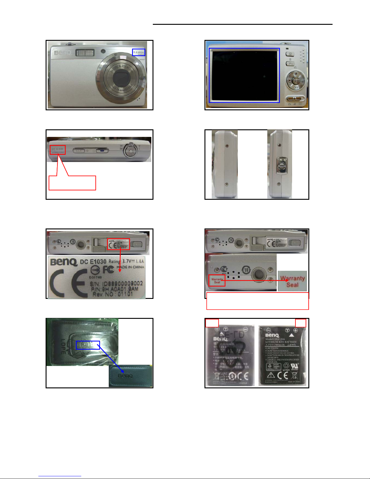
1.Front (Printing: 10.0 MEGA PIXELS )
2.Back (LCD with protective film: VG0692536290090*1EA)
3.Top 4.Camera sides
Printing:DC E1030
10.0 MEGA PIXELS
5.Bottom safety regulation label (VG0692106290090*1EA)
&protective film (VG0692535850090*1EA) 6.Warranty label (VG0692131985090*1EA)
Printing:DC E1030
10.0 MEGA PIXELS
Printing:DC E1030
10.0 MEGA PIXELS
W
arranty seal should cover screw completel
y
7.Camera bag(VG0692174710090*1EA) 8.Battery (VG0376121700021*1EA)
Front Back
Printing:DC E1030
10.0 MEGA PIXELS
Warranty seal should cover screw completely
and be pressed tightly by hand.
Front Back
Printing:DC E1030
10.0 MEGA PIXELS
Warranty seal should cover screw completely
and be pressed tightly by hand.
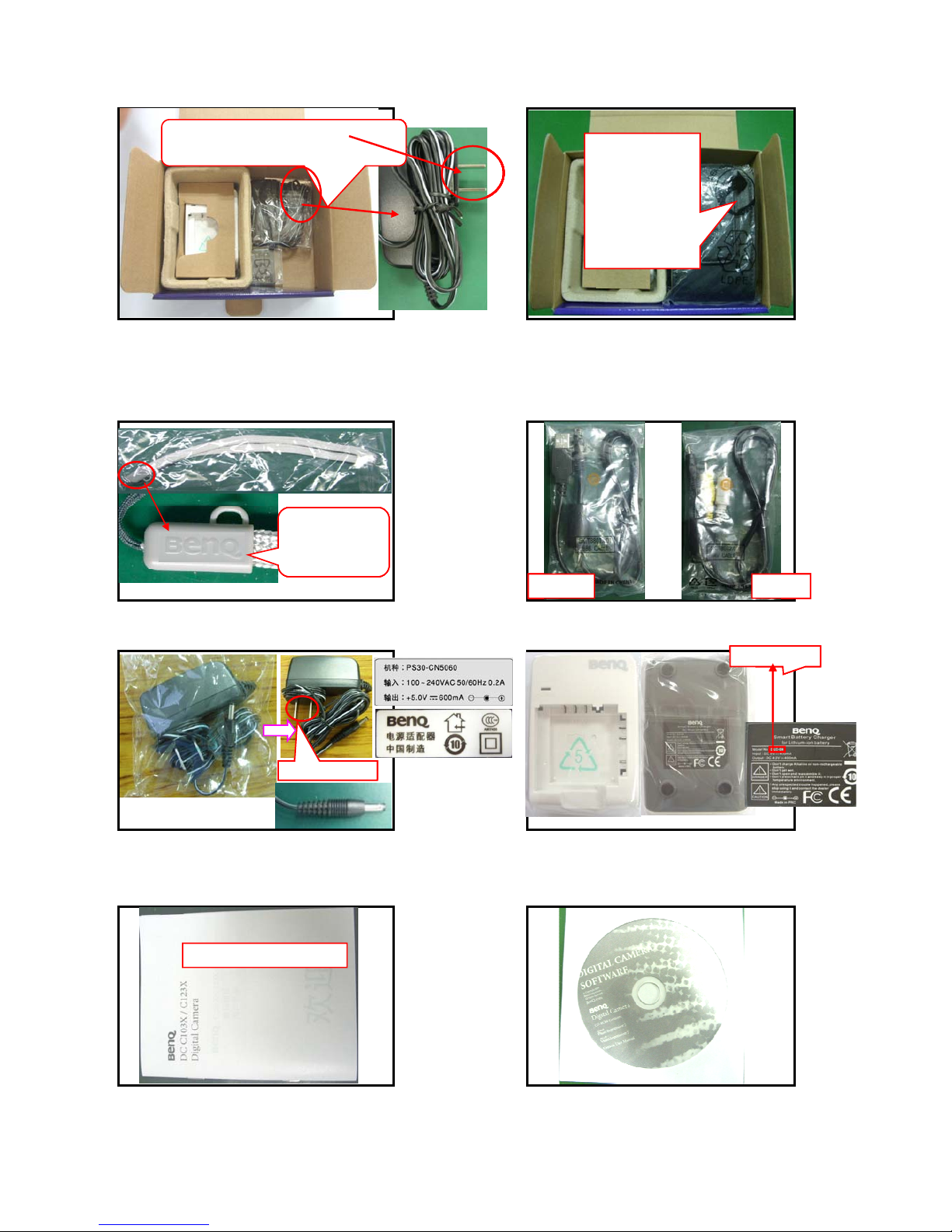
Page 7
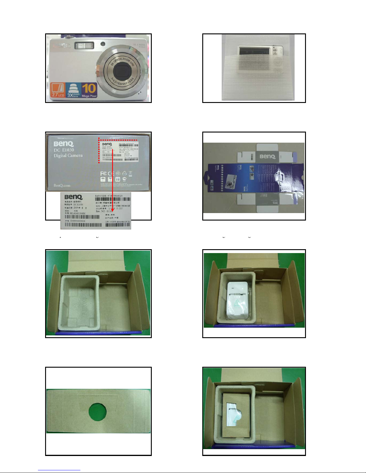
9.POP label position (VG0692135720090*1EA) 10.Camera entering bag(VG0692501980090*1EA)
11.Color box SN label position(VG069213ZBC0090*1EA)
12.Color box(VG0692416290090*1EA)
13.Paper box entering color box 14.Charger entering color box
pg
gg
Paper box(VG0692555530090*1EA) Charger(VG0376700820110*1EA)
15. Separator(VG0692435530190*1EA) 16. Separator entering paper box
Page 8
17.Wrist band and USB cable entering color bo
x
18.USB, AV cable, wrist band and camera
bag entering color box
USB cable facing
down,
AV cable facing
up, USB cable
under AV cable,
bent wrist band
facing up with
camera put on
Wrist band folded with head facing up,
USB cable head facing down
USB cable facing
down,
AV cable facing
up, USB cable
under AV cable,
bent wrist band
facing up with
camera put on
Wrist band folded with head facing up,
USB cable head facing down
20.USB cable (VR0592914631000*1EA)
19.Wrist band (VG0692183240091*1EA) AV cable (VR0592944631000*1EA)
USB cable facing
down,
AV cable facing
up, USB cable
under AV cable,
bent wrist band
facing up with
camera put on
Wrist band folded with head facing up,
USB cable head facing down
USB cable AV cable
USB cable facing
down,
AV cable facing
up, USB cable
under AV cable,
bent wrist band
facing up with
camera put on
Printing
with"BenQ"logo
Wrist band folded with head facing up,
USB cable head facing down
21.Adapter(VG0372203000060*1EA) 22.Charger (VG0376700820110*1EA)
Printing: DLC-08
Adapter with flat
USB cable AV cable
USB cable facing
down,
AV cable facing
up, USB cable
under AV cable,
bent wrist band
facing up with
camera put on
Printing
with"BenQ"logo
Wrist band folded with head facing up,
USB cable head facing down
23.User manual (VG0692206290190*1EA) 24.CD (VG03563100A1100*1EA)
Printing: DLC-08
Adapter with flat
USB cable AV cable
USB cable facing
down,
AV cable facing
up, USB cable
under AV cable,
bent wrist band
facing up with
camera put on
Printing
with"BenQ"logo
Wrist band folded with head facing up,
USB cable head facing down
Printing: DLC-08
Adapter with flat
USB cable AV cable
USB cable facing
down,
AV cable facing
up, USB cable
under AV cable,
bent wrist band
facing up with
camera put on
Printing
with"BenQ"logo
Wrist band folded with head facing up,
USB cable head facing down
Picture for reference only
Printing: DLC-08
Adapter with flat
USB cable AV cable
USB cable facing
down,
AV cable facing
up, USB cable
under AV cable,
bent wrist band
facing up with
camera put on
Printing
with"BenQ"logo
Wrist band folded with head facing up,
USB cable head facing down
Picture for reference only
Page 9
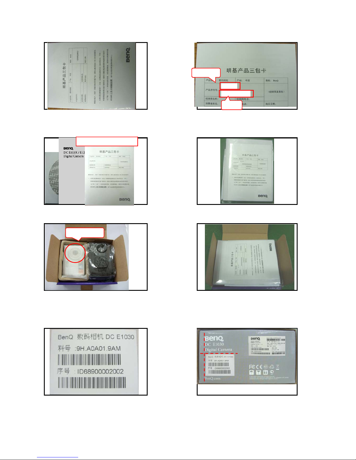
26.Model label (VG0692131363090*1EA)
25.Warranty card (VG0692311360094*1EA) & SN label (VG0692131364090*1EA)
Model label
27.Accessory position 28.Accessory inside PE bag(VG069250Z200002*1EA
)
DC E1030
IDM4900002002
Model label
SN label
DC E1030
IDM4900002002
Model label
SN label
Picture for reference only
29.Camera inside color box 30.User manual and accessory position
DC E1030
IDM4900002002
Model label
SN label
Picture for reference only
Lens facing up
DC E1030
IDM4900002002
Model label
SN label
Picture for reference only
31.Color box label:(VG0692133620590*1EA) 32.Color box label position
Lens facing up
DC E1030
IDM4900002002
Model label
SN label
Picture for reference only
Lens facing up
DC E1030
IDM4900002002
Model label
SN label
Picture for reference only
Lens facing up
DC E1030
IDM4900002002
Model label
SN label
Picture for reference only
Page 10
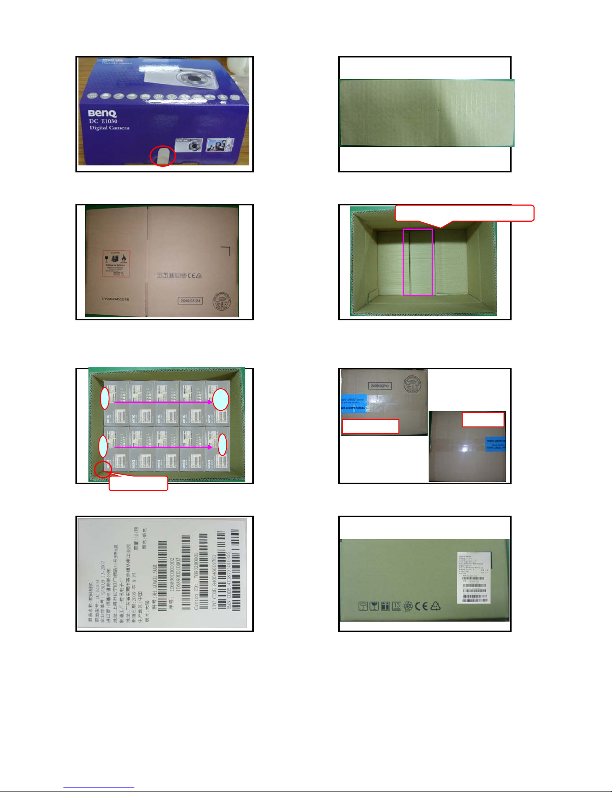
33.Color box seal label position (VG0692131332090*1EA) 34.Carton separator (VG0692435530090*0.1EA)
35.Carton(VG0692445530191*0.1EA) 36.Separator in carton
Bottom separator PN facing downBottom separator PN facing down
37.Color box in carton 38.Seal label (VG069213ZBC4090*2EA)position
Bottom separator PN facing down
Bottom separator PN facing down
Carton gap
1
5
10
6
Carton bottom
Carton top
40.Carton label position39.Carton label(VG069213ZBC5090*2EA)
Bottom separator PN facing down
Carton gap
1
5
10
6
Carton bottom
Carton top
Bottom separator PN facing down
Carton gap
1
5
10
6
Carton bottom
Carton top
Page 11
- -
Level 2 Disassembly / Assembly Flow & Calibration Procedure
Disassembly /Assembly
Caution :
1. Prevent cosmetic issue, please clean the table when disassembly.
2. Wear anti-static bracelet for ESD.
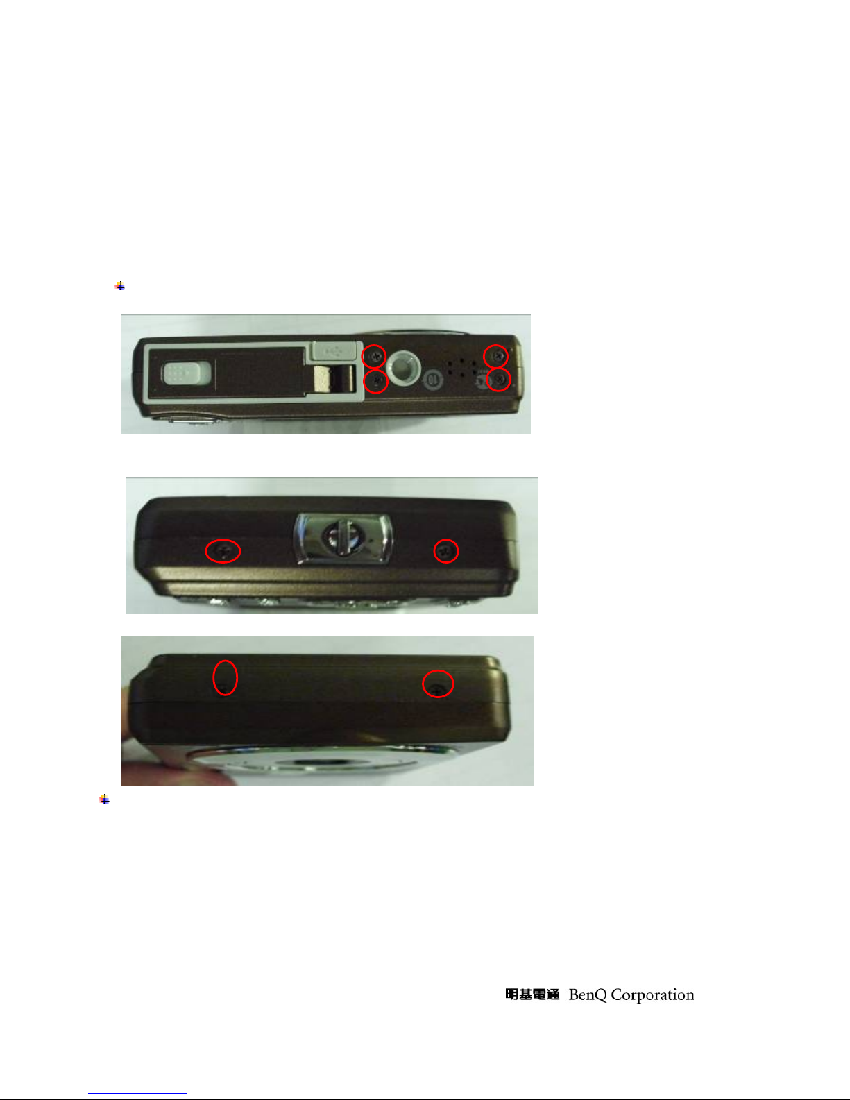
A. Disassemble Fron t/Rear Cover
Unscrew the screws of front/rear cover.
Open the cover and remove it as per arrow direction.
Page 12

- -
B. Disassemble strobe board, UI board and main board.
Disassemble strobe board. (Remark: Discharge the strobe board first.)
¾ Unscrew the screws Æremove the mylarÆdischarge the strobe board.
Unscrew the screws
Page 13

- -
Disassemble UI board
¾ Remove the mylarÆunscrew the screwsÆdissolder the connection between UI Board and
main boardÆtake UI board off.
Remove the mylar
Unscrew the screws
Discharge the strobe board
Remove the mylar
Page 14

- -
Disassemble Main board
¾ Dissolder the micr o phone, speake r and LED light connecti o n a reaÆunfold the FPC of LCD,
CCD and LENS Æunscrew the screws-Ædissolder the connection area between M/B and
ST/BÆtake M/B off
Unscrew the
screw
Dissolder the
connection between
M/B & UI board.
Page 15

- -
Dissolder microphone,speaker and
LED connection area.
Unfold the FPC of LCD panel to take
LCD panel off.
Unscrew the
screws
Unfold the FPC of CCD
Unfold the FPC of Lens
Page 16

- -
C. Disassemble the LCD panel, lens and chassis
Take the LCD panel offÆunscrew the screws of LCD frameÆtake Lens assembly off.
Dissolder the connection between Main board
and strobe board.
Page 17

- -
Take the LCD panel off取下
LCD
Unscrew the screws
Page 18

- -
This Service BOM is subject to change. Please check it on eSupport and SPO system before service parts order
release
Page 19

Page 20

Page 21

Page 22

Page 23

Page 24

- -
Calibration Procedure
A. How to check FW version?
1. Please press Set +Tele +Playback+ Power simultaneously.
B. How to update FW by using SD card?
1. Make sure the battery is full.
2. Format SD card and copy the program (SPCA5210.BRN) into card
3. Plug in camera
4. Press POWER + Flash mode of navigator button
FW version
Page 25

- -
5. The LED will flash and update FW. Once it finished, the camera will be power off automatically.
C. F/W update (replace M/B)
1. Start the F/W testing program FRM and check the following setting is correct or not (Fig 1).
Fig 1.
2. Ensure the cosmetic of camera is clean and without any scratch.
3. Insert the special cable (F/W programming cable—YELLOW COLOR) into the camera and PC
separately and m a k e sure the current is less than 0.01A.
4. Press “Power” button of camera (Fig. 2) to power on and press “ISP” button to update F/W.
5. Press “OK” button (Fig. 3) when the dialogue box showed “ISP Finished”.
Page 26

- -
6. The camera will be power off automatically and ensure the current is under 0.01A. Then remove the
special cable (F/W programming cable).
Fig. 2
Fig. 3
Caution:
1. Voltage setting: 3.0±0.1V.
2. F/W programming version: FRM[2.8.5.7.]
Page 27

- -
Calibration Procedure
(A) Auto Calibration (OB, AGC/WB、Meshut26、Meshut 80) & Infinite Focus Calibration
1. Insert the battery into the camera and press “Power, Playback, Tele and Set” button to access the
auto tes t m o d e .
2. The on screen display shows the “OB CLBT” message (Fig. 1). Put the camera in front of light source
box and make sure the camera is close to light source box tightly or you can shoot the black subject.
3. Tap “OK” button and the press “Set” button to test automatically. . When the dialogue box showed
“OK”(Fig. 2), it means the test is passed. If it shows “N G”, it means the test was failed.
4. Press the “Fn” button to back the main menu and select the AGC/WB.
5. The on screen display shows the “AGC/WB” message (Fig. 3). Put the camera in front of the light
source box and the LV setting is LV10.
6. Tap “OK” button and then press “Set” button. Calibration program will execute automatically.
7. When the on-screen display shows “OK” (Fig. 4), it means the test is passed. If it shows “NG”, it means
the test was failed.
Fig. 1
Fig. 2
Page 28

- -
Fig. 3
Fig. 4
8. The on screen display shows the “Meshut 26” message (Fig. 5). Put the camera in front of the light
source box adjust the LV value to LV 12 according to the instruction.
9. Tap “OK” button and then press “Set” button. Calibration program will execute automatically.
10. When the on-screen display shows “OK” (Fig. 6), it means the test is passed. If it shows “NG”, it means
the test was failed.
11. The on screen display shows the “Meshut 80” message (Fig. 7). Put the camera in front o f the light
source box and adjust the LV value to LV 14 according to the instruction.
12. Tap “OK” button and then press “Set” button. Calibration program will execute automatically.
13. When the on-screen display shows “OK” (Fig. 8), it means the test is passed. If it shows “NG”, it means
the test was failed.
14. The on screen display shows the “INF Focus ” (Fig. 9). It requires to use collimator to calibrate. Put the
camera in front of collimator.
15. Tap “OK” button and then press “Set” button. Calibration program will execute automatically.
16. When the on-screen display shows “OK” (Fig. 10), it means the test is passed. If it shows “NG”, it means
the test was failed.
Page 29

- -
Fig. 5
Fig. 6
Fig. 7
Page 30

- -
Fig. 8
Fig. 9
Fig. 10
Caution:
1. Voltage setting: 3.0+/-0.1V
2. Light source box brightness: K=1.3 LV=10.0±0.1(Color temperature:5500K)& LV=12.0±0.1& LV=14.0±0.1), LV
value is based on the BM3000 measurement data.
3. Brightness: Center: 250±30CD/M2﹔Peripheral : 300±30CD/M2.
Page 31

- -
(B) Flash WB Calibration
1. Put the camera on the fixture and press “Power+Tele+Set+Playback” to access the test mode
2. The on screen display shows “Flash WB” message (Fig. 11) . Shoot the subje ct which is in low-light
environment.
3. Tap “OK” button and press “Set” button, the test program will execute automatically.
4. The on screen display shows “OK (Fig. 12) once the test is passed. If it shows “NG”, it means the test was
failed.
Fig. 11
Fig. 12
Page 32

- -
(C ) USB mode setting
1. Press “Tele+Se t+Playback” to acc ess the test mode.
2. The on screen display shows “X USB MODE” message (Fig 13 ). Tap “OK” button and press “Set” button.
The test program will execute automatically.
3. The on screen display shows “PC to MS mode” once the test is passed.
4. Press “Power” to power it off.
Fig. 13
Page 33

- -
Trouble Shooting Guide
Preparation:
1. The necessary tools such as screwdriver, tweezers, iron solder, power supply, discharger and so on.
2. To wear anti-static wristband to prevent from components short.
3. Discharge the capacitor of strobe board firstly to avoid short.
A. Cannot Power On :
1. Cosmetic check.
I. Check any deformation / dirty / poor soldering of the spring of battery.
II. Check the soldering of battery’s spring of M/B.
2. Check the connection of each PCB.
01. Check the connection between M/B and ST Board.
02. Check the connection between M/B and LCD
03. Check the connection between M/B and LENS
3. Current = 0mA when power on.
01. Check U8 voltage output, if it is abnormal, please analyze its circuit..
02. Check the fuse is open or not. ( F1 & F2)
03. Check the S1 of strobe board.
U1
J6
J3
U3
U2
U7
U4
J2
Page 34

- -
B. Display abnormal
1. LCD display abnormal
01. Check the connection between J2 of M/B and LCD-FPC.
02. Check the function for LCD and U1 of MB.
03. Check the U8 output is normal or not.
2. Button abnormal
01. Check the peripheral components of U1
3. Image abnormal
01. Ensure the U8 output 3V2AGC .VCC13VCCD,VCCN7.5VCCD is normal. If there is abnormal signal
occurs, please check and replace.
02. Check the peripheral components of U1 and U7 of MB.
03. Check the peripheral components and CCD board
4. TV display abnormal
01. Check the function J4 of M/B
02. Check the connection between U1 of MB and other components.
5. Power LED is on, but LENS still doesn’t work.
01. Check the connection between J3 of M/B and LENS FPC.
02. Check the LENS is OK or not.
03. Ensure the output voltage of U8 is M 5V and LENS voltage
04. Check the peripheral components of U4 in the main-board.
J1
J5
J4
U8
Page 35

- -
C. Flash abnormal
1. Can’t charged
01. Check the soldering between ST/B and M/B.
02. Check the soldering of U1, T1 and peripheral components. .
2. Still charge when switch to strobe mode
01. Check the function and soldering of U1, R5 and R4 of ST/B.
02. Check the soldering between ST/B and M/B
3. Can’t Flash
01. Check the soldering between ST/B and M/B.
02. Check the function and soldering of U1, TR1, IC1 and flash light.
D. Other Defect:
01. No sound when press the key.
I. Make sure the setting is correct. ( enable )
II. Make sure the function of speaker and MB U1 with good soldering.
III. Make sure the peripheral components of MB U1 are in good condition.
02. Can’t record
I. Check the MIC function.
II. Check the MB U1 with good soldering.
03. Cannot read / write from SD card.
I. Check function of SD card.
II. Check the SD slot socket with good soldering.
Check the soldering of SD slot socket circuit.
IC1
U1
TR1
T1
Flash light
 Loading...