

D
Bedienungsanleitung
Operating manual
F
Notice d‘emploi
E
Instrucciones de servicio
Návod k obsluze
I
Istruzioni d’uso
Gebruiksaanwijzing
Instrukcja obsługi
S
Bruksanvisning
Benning Elektrotechnik & Elektronik GmbH & Co. KG
Münsterstraße 135 - 137
D - 46397 Bocholt
Telefon ++49 (0) 2871 - 93 - 0 • Fax ++49 (0) 2871 - 93 - 429
www.benning.de • eMail: duspol@benning.de
BENNING CC 1
D F E I S
D F E I S
Bild 1: Gerätefrontseite
Fig. 1: Front tester panel
Fig. 1: Panneau avant de l‘appareil
Fig. 1: Parte frontal del equipo
obr. 1: Přední strana přístroje
12/ 2005
ill. 1: Lato anteriore apparecchio
Fig. 1: Voorzijde van het apparaat
Rys.1: Panel przedni przyrządu
Fig. 1: Framsida
BENNING CC 1
Bild 2: Wechselstrommessung
Fig. 2: AC current measurement
Fig. 2: Mesure de courant alternatif
Fig. 2: Medición de corriente alterna
obr. 2: Měření střídavého proudu
12/ 2005
ill. 2: Misura corrente
Fig. 2: Meten van wisselstroom
Rys.2: Pomiar prądu przemiennego
Fig. 2: Växelströmsmätning
BENNING CC 1
alternata

D
Bedienungsanleitung
BENNING CC 1
Stromzangenadapter zur Wechselstrommessung
1. Benutzerhinweise
2. Sicherheitshinweise
3. Lieferumfang
4. Gerätebeschreibung
5. Allgemeine Angaben
6. Umgebungsbedingungen
7. Elektrische Angaben
8. Messen mit dem BENNING CC 1
9. Instandhaltung
10. Umweltschutz
1. Benutzerhinweise
Diese Bedienungsanleitung richtet sich an
- Elektrofachkräfte und
- elektrotechnisch unterwiesene Personen
Der BENNING CC 1 ist zur Messung in trockener Umgebung vorgesehen. Er darf
nicht in Stromkreisen mit einer höheren Nennspannung als 600 V AC eingesetzt
werden. (Näheres hierzu im Abschnitt 6. „Umgebungsbedingungen“).
In der Bedienungsanleitung und auf dem BENNING CC 1 werden folgende
Symbole verwendet:
Anlegen um GEFÄHRLICH AKTIVE Leiter oder Abnehmen von
diesen ist zugelassen.
Warnung vor elektrischer Gefahr!
Steht vor Hinweisen, die beachtet werden müssen, um Gefahren für
Menschen zu vermeiden.
Achtung Dokumentation beachten!
Das Symbol gibt an, dass die Hinweise in der Bedienungsanleitung
zu beachten sind, um Gefahren zu vermeiden.
Dieses Symbol auf dem BENNING CC 1 bedeutet, dass das
BENNING CC 1 schutzisoliert (Schutzklasse II) ausgeführt ist.
(AC) Wechsel-Strom.
Erde (Spannung gegen Erde).
Hinweis
Nach Entfernen des Klebeschildes „Warnung...“ (auf dem Batteriedeckel) erscheint der englische Text!
12/ 2005
BENNING CC 1
1

D
2. Sicherheitshinweise
Das Gerät ist gemäß
DIN VDE 0411 Teil 1/ EN 61010-1
gebaut und geprüft und hat das Werk in einem sicherheitstechnisch einwandfreien
Zustand verlassen.
Um diesen Zustand zu erhalten und einen gefahrlosen Betrieb sicherzustellen,
muss der Anwender die Hinweise und Warnvermerke beachten, die in dieser
Anleitung enthalten sind.
Das Gerät darf nur in Stromkreisen der Überspannungskategorie
III mit max. 300 V Leiter gegen Erde benutzt werden oder
Überspannungskategorie II mit max. 600 V Leiter gegen Erde
benutzt werden.
Beachten Sie, dass Arbeiten an spannungsführenden Teilen und
Anlagen grundsätzlich gefährlich sind. Bereits Spannungen ab
30 V AC und 60 V DC können für den Menschen lebensgefährlich sein.
Vor jeder Inbetriebnahme überprüfen Sie das Gerät und die
Leitungen auf Beschädigungen.
Ist anzunehmen, dass ein gefahrloser Betrieb nicht mehr möglich ist, ist das
Gerät außer Betrieb zu setzen und gegen unbeabsichtigten Betrieb zu sichern.
Es ist anzunehmen, dass ein gefahrloser Betrieb nicht mehr möglich ist,
- wenn das Gerät oder die Messleitungen sichtbare Beschädigungen aufweisen,
- wenn das Gerät nicht mehr arbeitet,
- nach längerer Lagerung unter ungünstigen Verhältnissen,
- nach schweren Transportbeanspruchungen.
Um eine Gefährdung auszuschließen
- berühren Sie die Messleitungen nicht an den blanken
Steckverbindern,
- stecken Sie die Messleitungen in die entsprechend
gekennzeichneten Messbuchsen am Multimeter
3. Lieferumfang
Zum Lieferumfang des BENNING CC 1 gehören:
3.1 ein Stück BENNING CC 1 mit einer fest angeschlossenen, spiralförmigen
Sicherheitsmessleitung mit 90 °-abgewinkelten 4 mm Sicherheitsstecker,
3.2 eine Stück Kompakt-Schutztasche,
3.3 eine Bedienungsanleitung.
4. Geräteschreibung
Der Stromzangenadapter BENNING CC 1 ist ein Messadapter für analoge und
digitale Multimeter und dient der Wechselstrommessungen bis 400 A.
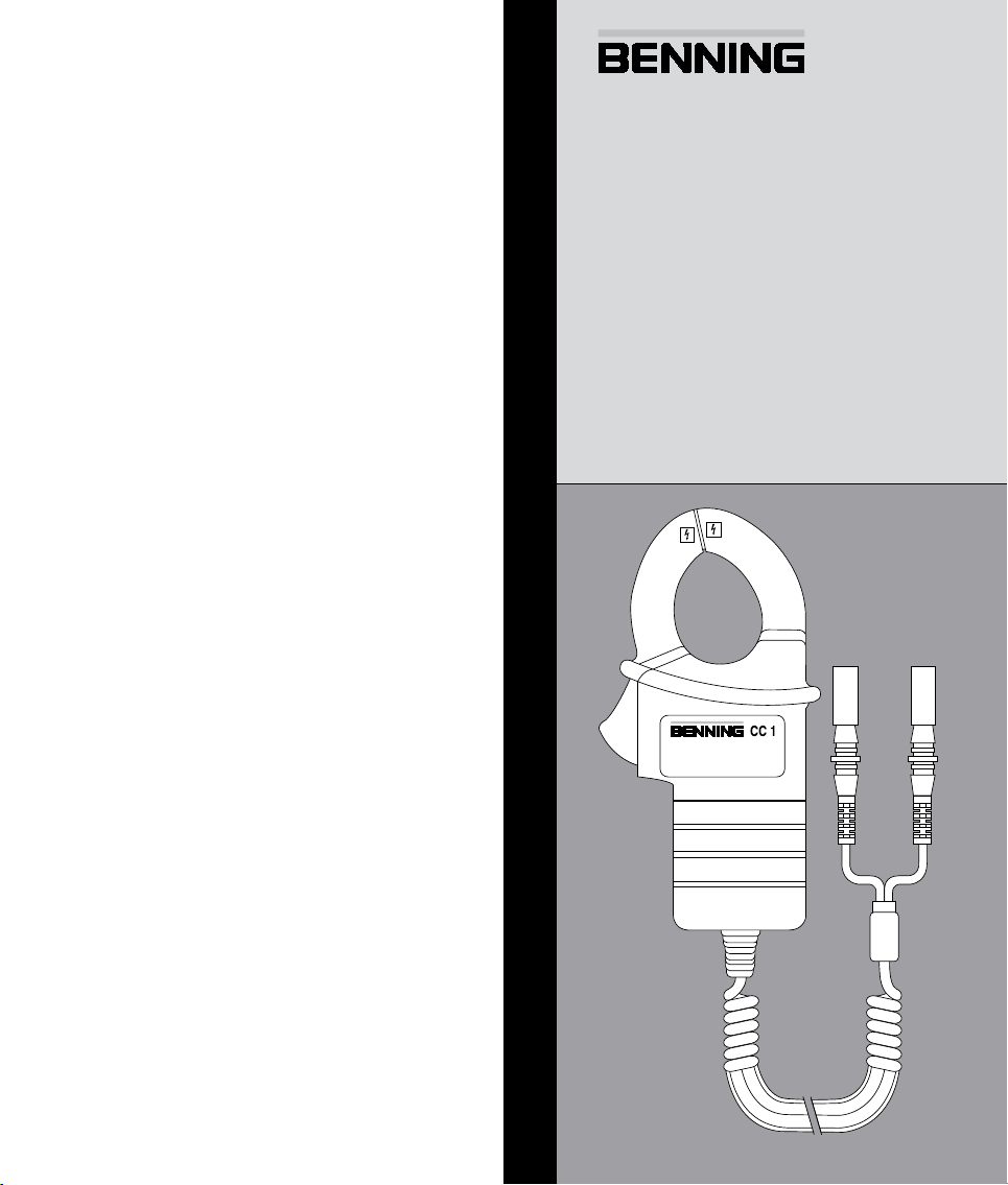
siehe Bild 1: Gerätefrontseite
Die im Bild 1 angegebenen Bedienelemente werden wie folgt beschrieben:
Messzange, zum Umfassen des einadrigen, wechselstromdurchossenen
Leiters.
Stromzangenwulst, schützt vor Leiterberührung.
Öffnungshebel, zum Öffnen und Schließen der Messzange.
Gehäuse mit Beschriftungsfeld
Spiralförmige Sicherheitsmessleitung mit 4 mm Sicherheitsstecker, rot,
schwarz, 90 °-abgewinkelt.
5. Allgemeine Angaben
5.1 Allgemeine Angaben zum Stromzangenadapter
Sensorart: Induktionsspule zum Erfassen von Wechselstrom
5.1.1 Temperaturkoefzient des Messwertes:
0,2 x (angegebene Messgenauigkeit)/ °C < 18 °C oder > 28 °C, bezogen
auf den Wert auf Referenztemperatur von 23 °C,
5.1.2 Größte Zangenöffnung: 30 mm,
5.1.3 Maximaler Leiterdurchmesser: 29 mm,
5.1.4 Geräteabmessungen:
(L x B x H) 148 x 72 x 36 mm,
Gerätegewicht:
250 g
12/ 2005
BENNING CC 1
2

D
6. Umgebungsbedingungen
- Der BENNING CC 1 ist für Messungen in trockenen Umgebungen vorgesehen,
- Barometrische Höhe bei Messungen: Maximal 2000 m,
- Überspannungskategorie IEC 60664/ IEC 61010, 300 V Kategorie III,
600 V Kategorie II,
- Verschmutzungsgrad 2 gemäß EN 61010-1,
- Schutzart: IP 30 (DIN VDE 0470-1 IEC/ EN 60529)
3 - erste Kennziffer: Schutz gegen Zugang zu gefährlichen Teilen und
Schutz gegen feste Fremdkörper, > 2,5 mm Durchmesser
0 - zweite Kennziffer: Kein Wasserschutz,
- Arbeitstemperatur und relative Luftfeuchte:
Bei Arbeitstemperatur von 0 °C bis 30 °C: relative Luftfeuchte kleiner 80 %,
Bei Arbeitstemperatur von 31 °C bis 40 °C: relative Luftfeuchte kleiner 75 %,
Bei Arbeitstemperatur von 41 °C bis 50 °C: relative Luftfeuchte kleiner 45 %,
- Lagerungstemperatur: Der BENNING CC 1 kann bei Temperaturen von
- 20 °C bis + 60 °C gelagert werden.
7. Elektrische Angaben
Bemerkung: Die Messgenauigkeit wird angegeben als Summe aus
- einem relativen Anteil des Messwertes und
- eines Stromwertes in A.
Die Messgenauigkeit gilt bei einer Temperatur von 23 °C ± 5 °C und einer relativen Luftfeuchtigkeit kleiner 75 %.
7.1 Wechselstrommessung
Messbereich Messwert Ausgang Messgenauigkeit
3 A 3 mV
400 A
Max. Ausgangsimpedanz: 75 Ω
8. Messen mit dem BENNING CC 1
8.1 Vorbereiten der Messung
Benutzen und lagern Sie den BENNING CC 1 nur bei den angegebenen Lagerund Arbeitstemperaturen, vermeiden sie dauernde Sonneneinstrahlung.
- Die zum Lieferumfang gehörenden spiralförmige Sicherheitsmessleitung
entspricht in Nennspannung und Nennstrom dem BENNING CC 1.
Die Sicherheitsmessleitung ist fest mit dem BENNING CC 1 verbunden und
nicht abnehmbar.
- Isolation der Sicherheitsmessleitungen überprüfen. Wenn die Isolation be-
schädigt ist, ist das BENNING CC 1 sofort auszusondern.
- Umfassen Sie keinen stromdurchossenen Leiter mit der Messzange bevor
Sie nicht den BENNING CC 1 mit einem Multimeter verbunden haben.
- Starke Störquellen in der Nähe des BENNING CC 1 können zu instabiler
Anzeige und zu Messfehlern führen.
- Keine Spannung an den Ausgangskontakten des BENNING CC 1 legen.
30 A 30 mV
350 A 350 mV
400 A 400 mV
± (1,9 % + 0,5 A)
bei 50 Hz - 60 Hz
± (3,2 % + 1 A)
bei 50 Hz - 60 Hz
Maximale Spannung gegen Erdpotential beachten!
Elektrische Gefahr!
Die höchste Spannung, die an dem BENNING CC 1 gegenüber Erdpotential liegen darf, beträgt 600 V.
12/ 2005
BENNING CC 1
3

D
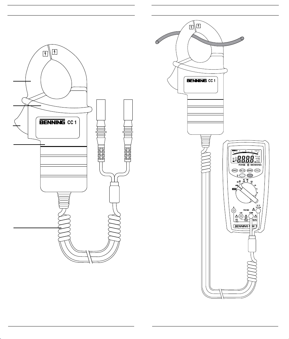
8.2 Wechselstrommessung
- Stellen Sie das Multimeter auf die Funktion Wechselspannungsmessung
(V AC) und wählen Sie einen Messbereich der Spannungen im Bereich von
1 mV bis 400 mV anzeigen kann.
- Den schwarzen 4 mm Sicherheitsstecker der spiralförmigen Sicherheits-
messleitung mit der COM-Buchse des Multimeters kontaktieren.
- Den roten 4 mm Sicherheitsstecker der spiralförmigen Sicherheitsmessleitung
mit der Buchse für den Spannungseingang (V) des Multimeters kontaktieren.
- Öffnungshebel betätigen und mit der Messzange den einadrigen,
stromdurchossenen Leiter umfassen.
- Den Spannungswert auf dem Multimeter ablesen und unter Berücksichtigung
des Umrechnungfaktors auf den Stromwert umrechnen.
Umrechnungsfaktor: 1 mV AC = 1 A AC
(siehe Gehäuse mit Beschriftungsfeld )
Beispiel:
Angezeigter Spannungswert am Multimeter: 0,350 V AC = 350 mV AC, ent-
spricht einen gemessenen Stromwert von 350 A AC.
9. Instandhaltung
Vor dem Öffnen den BENNING CC 1 unbedingt spannungsfrei
schalten! Elektrische Gefahr!
Die Arbeit an dem geöffneten BENNING CC 1 unter Spannung ist ausschließlich Elektrofachkräften vorbehalten, die dabei besondere Maßnahmen zur
Unfallverhütung treffen müssen.
So machen Sie den BENNING CC 1 spannungsfrei, bevor Sie das Gerät öffnen:
- Entfernen Sie zuerst den BENNING CC 1 vom Messobjekt.
- Entfernen Sie dann beide Sicherheitsmessleitung von dem Multimeter.
Der Stromzangenadapter BENNING CC 1 besitzt weder eine Batterie noch eine
Sicherung, so dass ein Öffnen in der Regel nicht nötig ist.
9.1 Sicherstellen des Gerätes
Unter bestimmten Voraussetzungen kann die Sicherheit im Umgang mit dem
BENNING CC 1 nicht mehr gewährleistet sein, z.B. bei:
- Sichtbaren Schäden am Gehäuse,
- Fehlern bei Messungen,
- Erkennbaren Folgen von längerer Lagerung unter unzulässigen Bedingungen
und
- Erkennbaren Folgen von außerordentlichen Transportbeanspruchungen.
In diesen Fällen ist das BENNING CC 1 sofort von der Messstelle zu entfernen
und gegen erneute Nutzung zu sichern.
9.2 Reinigung
Reinigen Sie das Gehäuse äußerlich mit einem sauberen und trockenen Tuch
(Ausnahme spezielle Reinigungstücher). Verwenden Sie keine Lösungs- und/
oder Scheuermittel, um das Gerät zu reinigen.
10. Umweltschutz
Bitte führen Sie das Gerät am Ende seiner Lebensdauer den zur
Verfügung stehenden Rückgabe- und Sammelsystemen zu.
12/ 2005
BENNING CC 1
4

Operating instructions
BENNING CC 1
clamp-on adapter for alternating current measurement
1. User notes
2. Safety note
3. Scope of delivery
4. Description of appliance tester
5. General information
6. Environment conditions:
7. Electrical specications
8. Making measurements with the BENNING CC 1
9. Maintenance
10. Environmental notice
1. User notes
These operating instructions are intended for
- skilled electricians and
- trained electrical personnel.
The BENNING CC 1 is intended for making measurements in dry environment.
It must not be used for making measurements in electric circuits with a
nominal voltage greater than 600 V DC/AC (for further details, see Section 6.
“Environmental conditions”).
The following symbols are used in these operating instructions and on the
BENNING CC 1:
Application around and removal from HAZARDOUS LIVE
conductors is permitted.
Warning of electrical danger!
Indicates instructions which must be followed to avoid danger to
persons.
Important, comply with the documentation!
The symbol indicates that the information provided in the operating
instructions must be complied with in order to avoid risks.
This symbol on the BENNING CC 1 means that the
BENNING CC 1 is totally insulated (protection class II).
(AC) Alternating current.
Ground (Voltage against ground).
Note
After unmark the adhesive label „Warnung...“ (on battery compartment lid) the
English text appears.
12/ 2005
BENNING CC 1
5

2. Safety note
The instrument is built and tested in accordance with
DIN VDE 0411 part 1/ EN 61010-1
and has left the factory in perfectly safe technical state.
To maintain this state and ensure safe operation of the appliance tester, the user
must observe the notes and warnings given in these instructions at all times.
The unit may be used only in power circuits within the over
voltage category III with a conductor for 300 V max. to earth
or over voltage category II with a conductor for 600 V max. to
earth.
Remember that work on electrical components of all kinds is
dangerous. Even low voltages of 30 V AC and 60 V DC may be
dangerous to human life.
Before starting the appliance tester up, always check it as well
as all cables and wires for signs of damage.
Should it appear that safe operation of the appliance tester is no longer possible,
it should be shut down immediately and secured to prevent it being switched
on accidentally.
It may be assumed that safe operation is no longer possible:
-
if the instrument or the measuring cables show visible signs of damage, or
- if the appliance tester no longer functions, or
- after long periods of storage under unfavourable conditions, or
- after being subjected to rough transport.
In order to avoid danger,
- do not touch the bare prod tips of the measuring cables
3. Scope of delivery
The scope of delivery for the BENNING CC 1 comprises:
3.1 one item BENNING CC 1 with a securely connected spiral type safety
3.2 One compact protective pouch,
3.3 One operating instructions manual
4. Description of appliance tester
The clamp-on adapter BENNING CC 1 is a measuring adapter for analog and
digital multimeters and is used for alternating current measurements up to
400 A.
See gure 1: Appliance front face
The display and operator control elements specied in Fig. 1 are designated
as follows:
Measuring pliers, for clamping on the single wire alternating current
Current probe bulge, protects against contact with conductor.
Opening lever, for opening and closing the measuring pliers.
Housing with label area
Spiral type safety measuring cable with 4 mm safety connector, red,
5. General information
5.1 General details on the clamp-on adapter
Sensor type: Induction coil for measuring alternating current
5.1.1 Temperature coefcient of the measured value:
0.2 x (stated measuring precision)/ °C < 18 °C or > 28 °C, related to the
5.1.2 Largest opening of pliers: 30 mm,
5.1.3 Maximum conductor diameter: 29 mm,
5.1.4 Appliance dimensions:
(L x W x H) = 148 x 72 x 36 mm
Appliance weight:
250 g
12/ 2005
connectors,
- insert the measurement lines in the appropriately
designated measuring sockets on the multimeter
measuring cable featuring a 90 °-angled 4 mm safety connector,
conductor.
black, 90 °-angled.
value for the reference temperature of 23° C.
BENNING CC 1
6

6. Environment conditions:
- The BENNING CC 1 is intended for making measurements in dry
environment.
- Maximum barometric elevation for making measurements: 2000 m,
- Overvoltage category IEC 60664/ IEC 61010, 300 V category III,
600 V category II,
- Contamination degree 2 according to EN 61010-1
- Protection Class: IP 30 (DIN VDE 0470-1 IEC/ EN 60529)
IP 30 means: Protection against access to dangerous parts and protection
against solid impurities of a diameter > 2.5 mm, (3 - first index). No
protection against water, (0 - second index).
- Operating temperature and relative humidity:
For operating temperatures from 0 °C to 30 °C: relative humidity less than 80 %
For operating temperatures from 31 °C to 40 °C: relative humidity less than 75 %
For operating temperature from 41 °C to 50 °C: relative humidity less than 45 %
- Storage temperature: The BENNING CC 1 can be stored at any temperature
in the range from 20 °C to + 60 °C ).
7. Electrical specications
Note: The measuring precision is specied as the sum of
- a relative fraction of the measured value and
- a current value in A.
The measurement precision applies at a temperature of 23 °C ± 5 °C and a
relative humidity less than 75 %.
7.1 Alternating current measurement
Measurement
range
400 A
Max. equivalent source resistance: 75 Ω
8. Making measurements with the BENNING CC 1
8.1 Preparations for making measurements
Operate and store the BENNING CC 1 only at the specied storage and
operating temperatures. Avoid continuous insulation.
- The nominal voltage and current ratings of the safety measuring
cables included in the scope of delivery correspond to the ratings of the
BENNING CC 1.
- The safety measuring cable is securely connected to the BENNING CC 1
and cannot be removed.
- Check the insulation of the safety measuring cables. Discard the
BENNING CC 1 immediately if the insulation is damaged.
- Do not clamp the measuring pliers on a live conductor before the
BENNING CC 1 has not been connected to a multimeter.
Strong sources of interference in the vicinity of the BENNING CC 1 can lead
to unstable readings and measuring errors.
- Do not apply any voltage to the output contacts of the BENNING CC 1.
Measured
value
3 A 3 mV
30 A 30 mV
350 A 350 mV
400 A 400 mV
Output Measurement precision
± (1,9 % + 0,5 A)
at 50 Hz - 60 Hz
± (3,2 % + 1 A)
at 50 Hz - 60 Hz
Do not exceed the maximum permitted voltage with respect to
earth potential! Electrical danger!
The highest voltage, that may be applied to the BENNING CC 1 against ground
potential, is 600 V.
12/ 2005
BENNING CC 1
7

8.2 Alternating current measurement
- Set the multimeter to the function “alternating voltage measurement” (V AC)
and select a measurement range that can display voltages from 1 mV to
400 mV.
- Contact the 4 mm safety connector of the spiral type safety measuring cable
with the COM jack of the multimeter.
- Contact the red 4 mm safety connector of the spiral type safety measuring
cable with the voltage input jack (V) of the multimeter.
- Opening lever Operate and use meas. pliers to clamp the single wire
live conductor.
- Read off the voltage value on the multimeter and convert to the current
value taking into account the conversion factor.
Conversion factor: 1 mV AC = 1 A AC
(see housing with label eld )
Example:
Voltage value indicated on multimeter: 0.350 V AC = 350 mV AC,
corresponds to a measured current value of 350 A AC.
9. Maintenance
Before opening the BENNING CC 1, make sure that it is
disconnected from all voltages! Electrical danger!
Work on the opened BENNING CC 1 under voltage may be carried out
only by skilled electricians with special precautions for the prevention of
accidents.
Make the BENNING CC 1 voltage free as follows before opening the
instrument:
- First remove the BENNING CC 1 from the measuring object.
- Then disconnect the two safety measuring cables from the multimeter.
The clamp-on adapter BENNING CC 1 has neither a battery nor a fuse so that
as a rule it does not need to be opened.
9.1 Securing the instrument
Under certain circumstances safe operation of the BENNING CC 1 is no longer
ensured, for example in the case of:
- Visible damage of the casing.
- Incorrect measurement results.
- Recognisable consequences of prolonged storage under improper
conditions.
- Recognisable consequences of extraordinary transportation stress.
In such cases the BENNING CC 1 must be disconnected from the measuring
point immediately and secured to prevent further utilisation.
9.2 Cleaning
Clean the casing externally with a clean dry cloth (exception: special cleaning
wipers). Avoid using solvents and/or scouring agents for cleaning the
instrument.
10. Environmental notice
At the end of the product’s useful life, please dispose of it at
appropriate collection points provided in your country.
12/ 2005
BENNING CC 1
8

F
Notice d’emploi
BENNING CC 1
Adaptateur à che électrique pour la mesure de courant alternatif
1. Remarques à l’attention de l’utilisateur
2. Consignes de sécurité
3. Fourniture
4. Description de l’appareil
5. Indications générales
6. Conditions d’environnement
7. Indication des valeurs électriques
8. Mesure avec le BENNING CC 1
9. Entretien
10. Information sur l’environnement
1. Remarques à l’attention de l’utilisateur
Cette notice d’emploi s’adresse aux
- électrotechniciens et
- aux personnes versées dans le domaine électrotechnique.
Le BENNING CC 1 est conçu pour effectuer des mesures dans un environnement
sec. Il ne faut pas l’utiliser dans des circuits dont la tension nominale est
supérieure à 600 V CA. (pour plus d’informations à ce sujet, consulter la section
6 « Conditions d’environnement »).
Les symboles suivants sont utilisés dans cette notice d’emploi et sur le
BENNING CC 1 :
Permet le déplacement et l’application autours d’un conducteur actif
non isolé.
Attention ! Danger électrique !
Se trouve devant les remarques devant être respectées afin d‘éviter
tout risque pour les personnes.
Attention ! Se conformer à la documentation !
Ce symbole indique qu‘il faut tenir compte des remarques contenues
dans cette notice d‘emploi pour éviter les risques.
Ce symbole sur le BENNING CC 1 signifie que le BENNING CC 1
est doté d‘une isolation double (classe de protection II).
(CA) Courant alternatif.
Terre (tension à la terre).
Instructions
Le texte en anglais apparaît en enlevant l’étiquette autocollante «Warnung...»
(située sur le capot batterie).
12/ 2005
BENNING CC 1
9

F
2. Consignes de sécurité
Cet appareil a été fabriqué et contrôlé conformément à
DIN VDE 0411 Partie 1/ EN 61010-1
et a quitté les ateliers de production dans un état technique parfait.
Pour conserver cet état et garantir un service sans risques, l’utilisateur doit se
conformer aux remarques et aux avertissements contenus dans cette notice
d’utilisation.
L’appareil doit être utilisé uniquement dans des circuits
électriques de la catégorie de protection contre les surtensions
III avec max. 300 V au max. à la terre ou de la catégorie de
protection contre les surtensions II avec max. 600 V au max. à
la terre.
Veuillez noter que les travaux au niveau d’éléments et
d’installations conducteurs de tension sont toujours dangereux.
Déjà les tensions de 30 V CA et 60 V CC peuvent être mortelles.
Assurez-vous, avant chaque mise en marche, que l’appareil et
les câbles ne sont pas détériorés.
Si l’on considère que l’utilisation sans risques n’est plus possible, il faut mettre
l’appareil hors service et le protéger contre toute utilisation involontaire.
Une utilisation sans risques n’est plus possible
- quand l’appareil ou les câbles de mesure présentent des détériorations
visibles,
- quand l’appareil ne fonctionne plus,
- après un stockage prolongé dans de mauvaises conditions,
- après des conditions difciles de transport.
Pour exclure tout danger,
- ne touchez pas les parties dénudées des câbles de mesure
au niveau des raccords enchables,
- raccordez les câbles de mesure aux douilles de mesure
repérées correspondantes du multimètre
3. Fourniture
Font partie de la fourniture du BENNING CC 1 :
1.1 un BENNING CC 1 à câble spiralé de mesure de sécurité relié xement
à connecteur de sécurité coudé de 90 º de 4 mm,
3.2 un étui compact de protection,
3.3 une notice d’emploi.
4. Description de l’appareil
L’adaptateur à che électrique BENNING CC 1 est un adaptateur de mesure
pour multimètres analogiques et numériques et sert à mesurer le courant
alternatif jusqu’à 400 A.
voir g. 1 : Partie avant de l’appareil
Les éléments de commande représentés à la g. 1 sont les suivants :
pince de mesure pour saisir le câble à courant alternatif à un conducteur.
bourrelet de pince électrique, protège contre le contact avec le
conducteur.
levier d’ouverture pour ouvrir et fermer la pince de mesure.
boîtier avec case d’inscription
câble spiralé de mesure de sécurité à connecteur de sécurité de 4 mm,
rouge, noir, coudé à 90 °.
5. Indications générales
5.1 Indications générales concernant l’adaptateur à che électrique
Type de sonde : bobine d’induction pour saisir le courant alternatif
5.1.1 Coefcient de température de la valeur mesurée :
0,2 x (précision de mesure indiquée)/ °C < 18°C ou > 28 °C, par rapport
à la valeur de température de référence de 23 °C,
5.1.2 Ouverture maximum de pince : 30 mm,
5.1.3 Diamètre maximum de conducteurs : 29 mm,
5.1.4 Dimensions de l’appareil :
(long. x larg. x haut.) 148 x 72 x 36 mm,
Poids de l’appareil : 250 g
12/ 2005
BENNING CC 1
10

F
6. Conditions d’environnement
- Le BENNING CC 1 est conçu pour procéder à la mesure dans des
environnements secs,
- hauteur barométrique pour les mesures : maximum 2000 m,
- catégorie de surtension IEC 60664/ IEC 61010, 300 V catégorie III, 600 V
catégorie II,
- degré d’encrassement 2 conformément à EN 61010-1,
- type de protection: IP 30 (DIN VDE 0470-1 IEC/ EN 60529),
IP 30 signifie: protection contre l’accès aux composants dangereux et
protection contre les impuretés solides > 2,5 mm de diamètre, (3 - premier
indice). Aucune protection contre l’eau, (0 - second indice).
- température de travail et humidité relative de l’air :
Avec une température de travail de 0 °C 0 à 30 °C : humidité relative de l’air
inférieure à 80 %,
Avec une température de travail de 31 °C à 40 °C : humidité relative de l’air
inférieure à 75 %,
Avec une température de travail de 41 °C à 50 °C : humidité relative de l’air
inférieure à 45 %,
- Température de stockage : Le BENNING CC 1 peut être stocké à des
températures de - 20 °C à + 60 °C.
7. Indication des valeurs électriques
Remarque : La précision de mesure est la somme
- d’une part relative de la valeur mesurée et
- d’une valeur de courant en A.
La précision de mesure est valable avec une température de 23 °C ± 5 °C et une
humidité relative de l’air inférieure à 75 %.
7.1 Mesure de courant alternatif
Plage de
mesure
400 A
Max. impédance initiale: 75 Ω
8. Mesure avec le BENNING CC 1
8.1 Préparation de la mesure
Utilisez et stockez le BENNING CC 1 uniquement conformément aux
températures de service et de stockage ; évitez de l’exposer longtemps aux
rayons du soleil.
- Les câbles de mesure de sécurité fournis correspondent à la tension
nominale et au courant nominal du BENNING CC 1.
Le câble de mesure de sécurité est relié xement au BENNING CC 1 et ne
peut pas être retiré.
- Contrôler l’isolation des câbles de mesure de sécurité. Si l’isolation est
détériorée, il faut immédiatement mettre le BENNING CC 1 hors service.
- Ne saisissez jamais de conducteur traversé par du courant avec la pince de
mesure avant d’avoir raccordé le BENNING CC 1 à un multimètre.
- Toutes fortes sources de parasites à proximité du BENNING CC 1 peuvent
entraîner un afchage instable et des erreurs de mesure.
- Ne pas appliquer de tension aux contacts de sortie du BENNING CC 1.
Valeur
mesurée
3 A 3 mV
30 A 30 mV
350 A 350 mV
400 A 400 mV
Sortie Précision de mesure
± (1,9 % + 0,5 A)
avec 50 Hz à 60 Hz
± (3,2 % + 1 A)
avec 50 Hz à 60 Hz
Tenir compte de la tension maximum au potentiel terrestre !
Danger électrique !
La tension maximum pouvant être appliquée au BENNING CC 1 face au
potentiel terrestre est de 600 V.
12/ 2005
BENNING CC 1
11

F
8.2 Mesure de courant alternatif
- Réglez le multimètre sur la fonction Mesure de tension alternative (V CA)
et sélectionnez une plage de mesure pouvant afcher des tensions dans la
plage de 1 mV à 400 mV.
- Mettre en contact le connecteur de sécurité noir de 4 mm du câble spiralé
de mesure de sécurité avec la douille COM du multimètre.
- Mettre en contact le connecteur de sécurité rouge de 4 mm du câble spiralé
de mesure de sécurité avec la douille d’entrée de tension (V) du multimètre.
- Actionner le levier d’ouverture et saisir à l’aide de la pince de mesure
le câble à un conducteur traversé par du courant.
- Lire la valeur de la tension sur le multimètre et la convertir en tenant compte
du facteur de conversion de la valeur de courant.
Facteur de conversion : 1 mV CA = 1 A CA
(voir boîtier avec case d’inscription )
Exemple :
Valeur de tension afchée sur le multimètre : 0,350 V CA = 350 mV CA,
correspond à une valeur mesurée de courant de 350 A CA.
9. Entretien
Il faut absolument mettre le BENNING CC 1 hors tension avant de
l’ouvrir ! Danger électrique !
Seuls des électrotechniciens devant prendre des mesures particulières
pour éviter les accidents sont autorisés à procéder à des travaux sur le
BENNING CC 1 ouvert sous tension.
Procédure à suivre pour mettre le BENNING CC 1 hors tension avant de
l’ouvrir :
- Retirez d’abord le BENNING CC 1 de l’objet mesuré.
- Retirez ensuite les deux câbles de mesure de sécurité du multimètre.
L’adaptateur à che électrique BENNING CC 1 ne comporte ni pile ni fusible de
sorte qu’il n’est normalement pas nécessaire de l’ouvrir.
9.1 Rangement sûr de l’appareil
Dans certaines conditions, la sécurité de travail avec le BENNING CC 1 peut ne
plus être garantie, p. ex., dans les cas suivants :
- dommages visibles sur le boîtier,
- erreurs lors des mesures,
- conséquences visibles d’un stockage prolongé dans des conditions
inadéquates et
- conséquences visibles de conditions difciles de transport.
Dans ces cas, il faut mettre immédiatement le BENNING CC 1 hors circuit, le
retirer du point de mesure et le protéger de manière à ne plus être utilisé.
9.2 Nettoyage
Nettoyez l’extérieur du boîtier avec un chiffon propre et sec (seule exception :
les chiffons de nettoyage spéciaux).
N’utilisez ni solvants ni produit de récurage pour nettoyer l’appareil.
10. Information sur l’environnement
Une fois le produit en fin de vie, veuillez le déposer dans un point de
recyclage approprié.
12/ 2005
BENNING CC 1
12

E
Instrucciones de servicio
BENNING CC 1
Adaptador de pinzas para medición de corriente alterna
Contenido
1. Informaciones para el usuario
2. Instrucciones de seguridad
3. Envergadura del suministro
4. Memoria descriptiva del aparato
5. Generalidades
6. Condiciones ambientales
7. Datos eléctricos
8. Medir con el BENNING CC 1
9. Mantenimiento
10. Advertencia
1. Informaciones para el usuario
Estas instruciones de operación están destinadas a
- personal especializado en electrotecnia y
- personas electrotécniamente instruidas
El BENNING CC 1 fue concebido para medición en ambiente seco. No puede
emplearse en circuitos eléctricos con tensiones nominales superiores a 600 V
AC (para más detalles ver bajo punto 6 „Condiciones ambientales„).
En estas instrucciones de servicio y en el multímetro BENNING CC 1 se
emplean los símbolos siguientes:
Está permitido aplicar y quitar el dispositivo de alrededor de
conductores con tensiones peligrosas.
¡Peligro eléctrico!
Este símbolo aparece en avisos a observar para evitar peligros para
personas.
¡Cuidado, observar la documentación!
Este símbolo indica que hay que observar los avisos en estas
instrucciones de servicio, para evitar peligro.
Este símbolo en el multímetro BENNING CC 1 indica que el
BENNING CC 1 viene ejecutado con aislamiento de protección
(clase de protección II).
(AC) corriente alterna.
tierra (tensión hacia tierra).
Nota
Antes de la etiqueta adhesiva „Warnung...“ (sobre la tapa del comnpartimento
de baterías) aparece el texto en Inglés.
12/ 2005
BENNING CC 1
13

E
2. Instrucciones de seguridad
El equipo es fabricado conforme a la norma
DIN VDE 0411 parte 1/ EN 61010-1,
vericado, y salió de fábrica en perfecto estado de seguridad.
Para manener el equipo en este perfecto estado de seguridad y garantizar
su funcionamiento sin peligro, el usuario debe observar las informaciones y
advertencias de peligros en este manual de servicio.
El BENNING CC 1 sólo está permitido para uso en circuitos
de corriente de la categoría de sobretensión III con conductor
frente a tierra máx. 300 V, o de la categoría de sobretensión II
con conductor frente a tierra máx. 600 V.
Tenga usted en cuenta que cualquier trabajo en partes e
instalaciones bajo tensión eléctrica por principio son peligrosos.
Ya pueden suponer peligro de muerte para las personas las
tensiones a partir de 30 V AC y 60 V DC.
Ante cada puesta en servicio, usted debe vericar que el equipo
y las conducciones no muestren daños.
Cuando ha de suponerse que ya no queda garantizado el funcionamiento sin
peligro, hay que desactivar el equipo y asegurarlo para evitar su accionamiento
involuntario.
Se supone que ya no queda garantizado su funcionamiento sin peligro,
cuando,
- el equipo o las conducciones de medición muestran daños visibles,
- cuando el equipo ya no funciona,
- tras un largo período de almacenamiento sin usarlo y bajo condiciones
desfavorables
- tras haber sufrido esfuerzos debido al transporte.
Para evitar peligros
- no tocar las conducciones de medición en las puntas de
medición al descubierto,
- enchufar las conducciones de medición en las
correspondientes hembrillas de medición marcadas
3. Envergadura del suministro
Envergadura del suministro BENNING CC 1:
3.1 una unidad de BENNING CC 1, con una conducción protegida de
medición ja en forma de espiral, con enchufe de seguridad 4 mm
acodado 90 °
3.2 bolsa compacta de protección, una unidad,
3.3 instrucciones de operación, una unidad,
4. Memoria descriptiva del aparato
El adaptador de pinzas BENNING CC 1 es un adaptador de medición para
multímetros análogos y digitales, y sirve para medición de corrientes alternas
de hasta 400 A.
ver g. 1: parte frontal del equipo
Los elementos de señalización y operación indicados en gura 1 se denominan
como sigue:
del conductor, para agarrar al conductor de de corriente alterna de un solo
hilo
borde del amperímetro de pinzas, sirve de protección contra el contacto
con el conductor
palanca de apertura, para abrir y cerrar el amperímetro de pinzas,
caja con zona para rotulación
conducción protegida de medición en forma de espiral con enchufe de
seguridad 4 mm de color rojo, negro, acodado 90 °
5. Generalidades
5.1 Generalidades del adaptador de pinzas
Tipo de sensor: Bobina de inducción para registrar corriente alterna
5.1.1 Coeciente de temperatura del valor medido:
0,2 x (exactitud de medición indicada)/ °C < 18 °C ó > 28 °C,
relativa a la temperatura de referencia de 23 °C,
12/ 2005
BENNING CC 1
14

E
5.1.2 Apertura máxima de las pinzas: 30 mm,
5.1.3 Diámetro máximo del conductor: 29 mm,
5.1.4 Dimensiones del equipo:
(largo x ancho x alto) = 148 x 72 x 36 mm
peso del equipo:
250 g
6. Condiciones ambientales
- El BENNING CC 1 fue concebido para medición en ambiente seco,
- Altura barométrica en las mediciones: máxima 2000 m,
- categoría de sobretensión/ categoría de colocación:
IEC 60664-1/ IEC 61010-1 (2001) 300 V categoría III; 600 V categoría II,
- Clase de suciedad: 2, conforme norma EN 61010-1,
- Clase de protección: IP 30 (DIN VDE 0470-1 IEC/ EN 60529),
Protección IP 30 significa: Primer dígito (3): Protección contra contactos
a partes peligrosas y contra objetos de un diámetro superior a 2,5 mm.
Segundo dígito (0): No protege del agua.
- Temperatura de trabajo y humedad atmosférica relativa:
Con temperaturas de trabajo entre 0 °C y 30 °C:
humedad atmosférica relativa inferior al 80 %.
Con temperaturas de trabajo entre 31 °C y 40 °C:
humedad atmosférica relativa inferior al 75 %.
Con temperaturas de trabajo entre 41 °C y 50 °C:
humedad atmosférica relativa inferior al 45 %.
- Temperatura de almacenamiento: El BENNING CC 1 permite
almacenamiento con temperaturas de - 20 °C hasta + 60 °C.
7. Datos eléctricos
Nota: La exactitud de medición se indica como suma resultando de
- una parte relativa al valor medido y
- de un valor de corriente en A.
Esta exactitud de medición vale con temperaturas de 23 °C ± 5 °C y una
humedad atmosférica relativa inferior al 75 %.
7.1 Medición de corriente alterna
rango de
medición
400 A
Max. resistencia equivalente de la fuente: 75 Ω
8. Medir con el BENNING CC 1
8.1 Preparar la medición
Úsese y almacénese el BENNING CC 1 sólo con las temperaturas de trabajo y
de almacenamiento indicados, evitando radiación solar directa.
- La conducción protegida de medición ja en forma de espiral que forma
parte del suministro en su tensión nominal como en su corriente nominal
equivale al BENNING CC 1.
La conducción protegida de medición está unida jamente al equipo
BENNING CC 1 y no se puede separar.
- Controlar el aislamiento de las conducciones protegidas de medición. Si el
aislamiento es defectuoso, eliminar en seguida la BENNING CC 1.
- No agarre usted ningún conductor que lleve corriente con las pinzas antes de
vericar que usted ha unido al equipo BENNING CC 1 con un multímetro.
- Fuentes de fuerte interferencia en las inmediaciones del BENNING CC 1
pueden causar inestabilidad en la indicación de valores y producir errores
de medición.
- No aplicar tensión a los contactos de salida del BENNING CC 1.
valor
medido
3 A 3 mV
30 A 30 mV
350 A 350 mV
400 A 400 mV
salida exactitud de medición
± (1,9 % + 0,5 A)
para 50 Hz - 60 Hz
± (3,2 % + 1 A)
para 50 Hz - 60 Hz
¡Observar la tensión máxima contra potencial de tierra!
¡Peligro de tensión eléctrica!
La máxima tensión que puede aplicarse al BENNING CC 1 frente al potencial
de tierra es de 600 V.
12/ 2005
BENNING CC 1
15

E
8.2 Medición de corriente alterna
- Seleccionar, en el multímetro, la función de medición de corriente alterna
(V AC) y seleccionar un rango de medición que pueda indicar las tensiones
de 1 mV hasta 400 mV.
- Contactar el enchufe de seguridad negro de 4 mm de la conducción protegida
de medición en forma de espiral con el enchufe COM del multímetro.
- Contactar el enchufe de seguridad rojo de 4 mm con la conducción
protegida de medición en forma de espiral con la entrada de tensión (V) del
multímetro.
- Activar la palanca abridora y agarrar, con las pinzas de medición el
conductor con corriente de un solo hilo.
- Leer el valor de tensión en el multímetro y calcular el valor de corriente/
intensidad teniendo en cuenta el factor para estos cálculos.
Factor de cálculo: 1 mV AC = 1 A AC
(ver caja con zona para rotulación )
Ejemplo:
Valor de tensión indicado en el multímetro: 0,350 V AC = 350 mV AC,
equivale a un valor de corriente/ intensidad medido de 350 A AC.
9. Mantenimiento
¡Eliminar sin falta toda tensión del BENNING CC 1 antes de
abrirlo! ¡Peligro de tensión eléctrica!
El trabajo en el BENNING CC 1 bajo tensión queda exclusivamente en
manos de personal especializado en electrotecnia, que debe tomar
medidas especiales para evitar accidentes.
Así se elimina todo tipo de tensiones del BENNING CC 1 antes de abrir el
equipo:
- Quitar primero la BENNING CC 1 del objeto de medición.
- Después, eliminar ambas conducción protegida de medición del
multímetro.
El adaptador de pinzas BENNING CC 1 no cuenta con batería ni tampoco con
un seguro, de modo que normalmente no es necesario abrirlo.
9.1 Guardar seguro el equipo
Dadas determinadas condiciones, no se puede garantizar ya la seguridad de
uso del BENNING CC 1, por ejemplo habiendo:
- daños visibles en la carcasa,
- errores en mediciones,
- Huellas visibles como consecuencia de almacenamiento durante largo
tiempo bajo condiciones no admitidas y
- Huellas visibles resultantes de esfuerzo extraordinario en el transporte.
Presentándose tales casos, se debe desconectar inmediatamente el BENNING
CC 1, alejarlo del punto de medición y guardarlo seguro contra el uso.
9.2 Limpieza
Limpiar la supercie de la carcasa con un paño limpio y seco (excepcionalmente
con paños especiales de limpieza). No aplique agentes disolventes o abrasivos
para limpiar el equipo.
10. Advertencia
Para preservar el medio ambiente, al final de la vida útil de su
producto, deposítelo en los lugares destinado a ello de acuerdo con
la legislación vigente.
12/ 2005
BENNING CC 1
16

Návod k použití
BENNING CC 1
Čelisťový adaptér pro měření střídavého proudu
1. Pokyny pro uživatele
2. Bezpečnostní pokyny
3. Obsah dodávky
4. Popis přístroje
5. Všeobecné údaje
6. Podmínky prostředí
7. Elektrické údaje
8. Měření přístrojem BENNING CC 1
9. Udržování
10. Ochrana životního prostředí
1. Pokyny pro uživatele
Tento návod k použití slouží pro
- odborné pracovníky elektro a
- elektrotechnicky vyškolené osoby
Přístroj BENNING CC 1 je určen pro měření v suchém prostředí. Nesmí být
používán v elektrických obvodech s napětím vyšším než 600 V AC. (Více
v odstavci 6 „Podmínky prostředí“).
V návodu k použití a na přístroji BENNING CC 1 jsou používány následující
symboly:
Je dovoleno přiložit NEBEZPEČNĚ AKTIVNÍ vodiče nebo je
odstranit.
Varování před elektrickým nebezpečím!
Stojí před pokyny, které je třeba dodržovat pro zamezení nebezpečí
pro osoby.
Pozor: dbát na dokumentaci!
Symbol udává, že je třeba dodržovat pokyny uvedené v návodu
k použití, aby nevzniklo nebezpečí pro osoby.
Tento symbol na přístroji BENNING CC 1 označuje, že přístroj
BENNING CC 1 má provedení s ochrannou izolací (ochranná třída
II).
(AC) střídavý proud.
Uzemnění (napětí vůči zemi).
12/ 2005
10/ 2004
BENNING CC 1
BENNING CC 1
17
17

2. Bezpečnostní pokyny
Přístroj je konstruován a zkoušen podle
DIN VDE 0411 část 1/ EN 61010-1
a byl expedován z podniku v bezvadném stavu z bezpečnostně technického
hlediska.
Pro zachování tohoto stavu a zajištění bezpečného provozu je uživatel povinen
dodržovat pokyny a varování, která jsou uvedená v tomto návodu.
Přístroj smí být používán pouze v obvodech přepěťové kategorie
III s napětím max. 300 V proti zemi nebo v obvodech přepěťové
kategorie II s napětím max. 600 V proti zemi.
Mějte na zřeteli, že práce na vodivých částech a zařízeních jsou
zásadně nebezpečné. Již napětí od 30 V AC a 60 V DC mohou
být lidem životu nebezpečné.
Před každým zahájením provozu prověřte, že přístroj a vedení
jsou nepoškozené.
Je třeba si uvědomit, že pokud není dále možný bezpečný provoz, je třeba
provoz přístroje zastavit a zajistit proti dalšímu používání.
Je třeba si uvědomit, že není dále možný bezpečný provoz v případě,
- že přístroj nebo měřící vedení vykazuji viditelné poškození,
- že přístroj již nepracuje,
- po delším skladování v nepříznivých podmínkách,
- po obtížném namáhání při přepravě.
K vyloučení ohrožení
- nedotýkejte se měřících vodičů na neizolovaných místech,
- zapojujte vodiče do zdířek označených odpovídajícím
způsobem na Multimetru
3. Obsah dodávky
K obsahu dodávky přístroje BENNING CC 1 patří:
3.1 jeden kus přístroje BENNING CC 1 s pevně připojeným, spirálovým
bezpečnostním měřícím vedením s 90 °-zahnutou 4 mm bezpečnostní
vidlicí,
3.2 jeden kus kompaktní ochranné brašny,
3.3 návod k použití.
4. Popis přístroje
Čelisťový adaptér BENNING CC 1 je měřící adaptér pro analogový a digitální
Multimeter a slouží k měření střídavého proudu do 400 A.
viz. obr. 1: Čelní strana přístroje
Prvky uvedené na obr. 1 jsou popsány následujícím způsobem:
Měřící kleštiny, pro obejmutí jednožilového vodiče, kterým protéká střídavý
proud.
tvar kleští, chrání před dotykem s vodičem.
Páka pro otevírání a zavírání kleští.
Pouzdro s popiskou
Spirálové bezpečnostní měřící vedení s 4 mm bezpečnostní vidlicí,
červené, černé, zahnutí 90 °.
5. Všeobecné údaje
5.1 Všeobecné údaje k čelisťovému adaptéru
Druh senzoru: Indukční cívka k měření střídavého proudu
5.1.1 Teplotní koeficient naměřené hodnoty:
0,2 x (udaná přesnost měření)/ °C < 18 °C nebo > 28 °C, vztažená
k hodnotě referenční teploty 23 °C,
5.1.2 Maximální otevření kleští: 30 mm,
5.1.3 Maximální průměr vodiče: 29 mm,
5.1.4 Rozměry přístroje:
(L x B x H) 148 x 72 x 36 mm,
Hmotnost přístroje:
250 g
12/ 2005
BENNING CC 1
18

6. Podmínky prostředí
- Přístroj BENNING CC 1 je určen pro měření v suchém prostředí,
- Barometrická výška při měření: max. 2000 m,
- Přepěťová kategorie IEC 60664/ IEC 61010, 300 V Kategorie III,
600 V Kategorie II,
- Stupeň znečištění 2 podle EN 61010-1,
- Krytí: IP 30 DIN VDE 0470-1 IEC/EN 60529,DIN VDE 0470-1 IEC/EN 60529,,
Význam IP 30: Ochrana proti malým cizím předmětům, proti dotyku
nářadím, drátem a podobně s průměrem > 2,5 mm, (3 - první číslice).
Žádná ochrana před vodou, (0 - druhá číslice).
- Pracovní teplota relativní vlhkost vzduchu:
Při pracovní teplotě od 0 °C do 30 °C: relativní vlhkost méně než 80 %,
Při pracovní teplotě od 31 °C do 40 °C: relativní vlhkost méně než 75 %,
Při pracovní teplotě od 41 °C a 50 °C: relativní vlhkost méně než 45 %,
- Teplota pro skladování: přístroj BENNING CC 1 může být skladován při
teplotách v rozmezí od - 20 °C bis + 60 °C.
7. Elektrické údaje
Poznámka: Přesnost měření je udávána jako součet
- relativního podílu naměřené hodnoty a
- hodnoty proudu v A.
Přesnost měření platí při teplotě 23 °C ± 5 °C a relativní vlhkosti vzduchu menší
než 75 %.
7.1 Měření střídavého proudu
Rozsah měření Hodnota měření Výstup Přesnost měření
400 A
Max. výstupnί impedance: 75 Ω
8. Měření přístrojem BENNING CC 1
8.1 Příprava měření
Přístroj BENNING CC 1 používejte a skladujte pouze při uvedených skladovacích
a provozních teplotách, chraňte před trvalým slunečním zářením.
- Spirálové bezpečnostní vedení, které je součástí dodávky, odpovídá
jmenovitému napětí a jmenovitému proudu přístroje BENNING CC 1.
Bezpečnostní měřící vedení je s přístrojem BENNING CC 1 pevně spojeno
a nelze jej odejmout.
- Prověřte izolaci bezpečnostního měřící vedení. Pokud je izolace poškozená,
je nutné přístroj BENNING CC 1 ihned vyřadit.
- Neuchopujte měřícími kleštěmi žádný vodič, kterým protéká proud, dokud
nespojíte přístroj BENNING CC 1 s Multimetrem.
- Silné zdroje rušení v blízkosti přístroje BENNING CC 1 mohou vést
k nestabilnímu zobrazování a k chybám měření.
- Nezatěžovat výstupní kontakty přístroje BENNING CC 1 napětím.
3 A 3 mV
30 A 30 mV
350 A 350 mV
400 A 400 mV
± (1,9 % + 0,5 A)
bei 50 Hz - 60 Hz
± (3,2 % + 1 A)
bei 50 Hz - 60 Hz
Dbejte na maximální napětí proti zemi!
Elektrické nebezpečí!
Nejvyšší napětí přístroje BENNING CC 1 proti zemi činí 600 V.
8.2 Měření střídavého proudu
- Nastavte Multimeter na funkci měření střídavého napětí (V AC) a vyberte
rozsah měření pro napětí v rozmezí od 1 mV do 400 mV.
- Černou bezpečnostní vidlici 4 mm u spirálového bezpečnostního měřícího
vedení spojit s COM-zdířkou na Multimetru.
- Červenou bezpečnostní vidlici 4 mm u spirálového bezpečnostního
měřícího vedení spojit se zdířkou pro vstup napětí (V) na Multimetru.
- Otevírací páka : obejměte měřícími kleštěmi jednožilový vodič
protékaný střídavým proudem.
- Odečtěte hodnotu napětí na Multimetru a při zohlednění přepočítacího
faktoru přepočtěte na hodnotu proudu.
Přepočítací faktor: 1 mV AC = 1 A AC
(viz. pouzdro s popiskou )
12/ 2005
BENNING CC 1
19

Příklad:
Zobrazená hodnota napětí na Multimetru: 0,350 V AC = 350 mV AC,
odpovídá naměřené hodnotě proudu 350 A AC.
9. Údržba
Před otevřením přístroje BENNING CC 1 v každém případě
odpojte od napětí! Elektrické nebezpečí!
Práce na otevřeném přístroji BENNING CC 1 pod napětím je určena
výhradně elektrotechnicky vyškoleným osobám, které přitom musejí
dodržovat zvláštní opatření pro zabránění nehodám.
- Nejprve odstraňte přístroj BENNING CC 1 od měřeného objektu.
- Poté odstraňte obě bezpečnostní vedení od multimeteru.
Čelisťový adaptér BENNING CC 1 není vybaven baterií ani pojistkou, takže jeho
otvírání zpravidla není nutné.
9.1 Zajištění přístroje
Za určitých předpokladů není možné dále zajistit bezpečnost při používání
přístroje BENNING CC 1, např. při:
- viditelném poškození pouzdra,
- chybách při měření,
- zjistitelných následcích dlouhého skladování za nepřípustných podmínek a
- zjistitelných následcích mimořádného namáhání při přepravě.
V těchto případech je nutné přístroj BENNING CC 1 ihned odstranit z místa
měření a zajistit proti dalšímu použití.
9.2 Čištění
Provádějte čištění pouzdra zvenku čistým a suchým hadříkem (výjimkou jsou
speciální čistící ubrousky). Nepoužívejte k čištění přístroje rozpouštědla a/ nebo
čistící prostředky.
10. Ochrana životního prostředí
Po ukončení životnosti přístroje prosím předejte přístroj příslušným
sběrným místům na likvidaci.
12/ 2005
BENNING CC 1
20

I
Istruzioni d’uso
BENNING CC 1
Adattatore a pinza per misure di corrente alternata
1. Avvertenze per l’utente
2. Avvertenze sulla sicurezza
3. Dotazione standard
4. Descrizione apparecchio
5. Dati di carattere generale
6. Condizioni ambientali
7. Dati elettrici
8. Misure con il BENNING CC 1
9. Manutenzione
10. Informazioni ambientali
1. Avvertenze per l’utente
Le presenti istruzioni sono destinate a
- elettrotecnici e
- personale qualicato in elettrotecnica
Il BENNING CC 1 è previsto per misure in ambiente asciutto e non deve essere
impiegato in circuiti con una tensione nominale superiore a 600 V CA (per
maggiori dettagli vedere la sezione 6 “Condizioni ambientali”).
Nelle presenti istruzioni e sul BENNING CC 1 vengono usati i seguenti simboli:
Applicazione e rimozione consentite su conduttori PERICOLOSAMENTE ATTIVI.
Pericolo di scariche elettriche!
Si trova nelle avvertenze che devono essere osservate per evitare
pericoli per il personale.
Prestare attenzione alla documentazione!
Questo simbolo indica che si devono osservare le avvertenze
contenute nelle istruzioni d’uso, al ne di evitare pericoli.
Questo simbolo riportato sul BENNING CC 1 indica che l’adattatore
dispone di isolamento di protezione (classe di protezione II).
(CA) Corrente alternata
Terra (tensione verso terra).
Avvertenza
Dopo aver rimosso l‘etichetta adesiva „Warnung...“ (sul coperchio della batteria)
appare il testo inglese!
12/ 2005
BENNING CC 1
21

I
2. Avvertenze sulla sicurezza
L’apparecchio è stato costruito e collaudato in conformità a
DIN VDE 0411 Parte 1/ EN 61010-1
ed ha lasciato lo stabilimento in un ineccepibile stato di sicurezza.
Per mantenere tale stato e garantire un esercizio sicuro, l’utente deve osservare
le avvertenze e le annotazioni di avviso contenute nelle presenti istruzioni.
L’apparecchio può essere utilizzato solo in circuiti della
categoria di sovratensione III con max. 300 V conduttore verso
terra oppure della categoria di sovratensione II con max. 600 V
conduttore verso terra.
Tenere presente che i lavori eseguiti su parti ed impianti sotto
tensione sono fondamentalmente pericolosi. Già tensioni da 30
V CA e 60 V CC possono implicare pericolo di morte.
Prima di ogni messa in funzione controllare che l’apparecchio e
i cavi non presentino danni.
Se si presume che non sia più possibile un esercizio sicuro, si deve allora mettere
fuori servizio l’apparecchio ed al sicuro da un esercizio non intenzionale.
È da presumere che non sia più possibile un esercizio sicuro,
- se l’apparecchio o i circuiti di misura presentano danni evidenti,
- se l’apparecchio non funziona più,
- dopo lungo stoccaggio dell’apparecchio in condizioni sfavorevoli,
- in seguito a condizioni particolari di trasporto.
Per escludere qualsiasi pericolo
- non toccare i puntali nudi dei cavetti,
- inlare gli spinotti dei cavetti nelle apposite boccole.
3. Dotazione standard
Fanno parte della dotazione standard del BENNING CC 1:
3.1 un adattatore BENNING CC 1 con un cavetto di sicurezza, collegato in
modo sso, spiraliforme, munito di uno spinotto di sicurezza da 4 mm a
90°,
3.2 una custodia compatta,
3.3 istruzioni d’uso.
4. Descrizione apparecchio
L’adattatore a pinza BENNING CC 1 è un adattatore di misura per multimetri
analogici e digitali e serve per misure di corrente alternata no a 400 A.
Si veda Ill. 1: Lato anteriore apparecchio
Gli elementi di comando indicati nell’ill. 1 sono descritti come segue:
pinza di misura, per avvolgere i conduttori unipolari percorsi da corrente
alternata,
collare della pinza, protegge dal contatto con il conduttore,
leva di apertura, per aprire e chiudere la pinza,
involucro con campo per scritte
cavetto di sicurezza spiraliforme, munito di uno spinotto di sicurezza da
4 mm, rosso, nero, piegato a 90°.
5. Dati di carattere generale
5.1 Dati generali sull’adattatore di corrente
Tipo di sensore: bobina di induzione per il rilevamento della corrente alternata
5.1.1 Coefciente di temperatura del valore misura:
0,2 x (precisione di misura indicata)/ °C < 18 °C o > 28 °C, in relazione
al valore della temperatura di riferimento di 23 °C,
5.1.2 Apertura massima pinza: 30 mm,
5.1.3 Diametro massimo conduttore: 29 mm,
5.1.4 Dimensioni apparecchio: (lungh. x largh. x alt.) 148 x 72 x 36 mm,
Peso apparecchio: 250 g
6. Condizioni ambientali
- Il BENNING CC 1 è previsto per l’esecuzione di misure in ambiente
asciutto,
- altezza barometrica nell’esecuzione di misure: max. 2000 m,
- categoria sovratensione IEC 60664/ IEC 61010, 300 V categoria III, 600 V
12/ 2005
BENNING CC 1
22

I
categoria II,
- grado di inquinamento 2 in conformità a EN 61010-1,
- Tipo di protezione: IP 30 (DIN VDE 0470-1 IEC/ EN 60529),
IP 30 significa: protezione contro l’accesso a parti pericolose e protezione
contro corpi estranei solidi > 2,5 mm di diametro, (3 - prima cifra). Nessuna
protezione contro l’acqua, (0 - seconda cifra).
- temperatura di funzionamento ed umidità relativa dell’aria:
con una temperatura di funzionamento da 0 °C a 30 °C: umidità relativa
dell’aria inferiore a 80 %,
con una temperatura di funzionamento da 31 °C a 40 °C: umidità relativa
dell’aria inferiore a 75 %,
con una temperatura di funzionamento da 41 °C a 50 °C: umidità relativa
dell’aria inferiore a 45 %,
- temperatura di stoccaggio: il BENNING CC 1 può essere immagazzinato a
temperatura da - 20 °C a +60 °C.
7. Dati elettrici
Annotazione: la precisione di misura viene indicata come somma di
- una quota relativa del valore misura
- di un valore di corrente in A.
Tale precisione di misura è valida ad una temperatura di 23 °C ± 5 °C ed una
umidità relativa dell’aria inferiore a 75 %.
7.1 Misure di corrente alternata
Portata Valore misura Uscita Precisione misure
3 A 3 mV
400 A
Impendenza d’uscita max.: 75 Ω
8. Misure con il BENNING CC 1
8.1 Preparazione delle misure
Conservare ed usare il BENNING CC 1 solo alle condizioni di stoccaggio
e di temperatura di funzionamento indicate, evitare l’esposizione continua
all’irraggiamento solare.
- Il cavetto di sicurezza spiraliforme, in dotazione, corrisponde per tensione
e corrente nominali al BENNING CC 1. Il cavetto di sicurezza è collegato in
modo sso con il BENNING CC 1 e non è possibile rimuoverlo.
- Controllare l’isolamento dei cavetti di sicurezza. Se l’isolamento è
danneggiato, il BENNING CC 1 deve essere subito escluso dall’impiego.
- Non avvolgere con la pinza su conduttori percorsi da corrente, se il
BENNING CC 1 non è stato prima collegato con un multimetro.
- Forti fonti di disturbo in prossimità del BENNING CC 1 possono causare
indicazioni instabili ed errori di misura.
- Non applicare tensione ai contatti d’uscita del BENNING CC 1.
Osservare la tensione massima rispetto al potenziale di terra!
Pericolo di scariche elettriche!
30 A 30 mV
350 A 350 mV
400 A 400 mV
± (1,9 % + 0,5 A)
da 50 Hz a 60 Hz
± (3,2 % + 1 A)
da 50 Hz a 60 Hz
La tensione massima, che può essere presente sul BENNING CC 1 rispetto al
potenziale di terra, è di 600 V.
8.2 Misure di corrente alternata
- Impostare il multimetro per la funzione misure di tensione alternata (V CA)
e selezionare un campo misure che possa indicare le tensioni nel campo da
1 mV a 400 mV.
- Inserire lo spinotto di sicurezza nero da 4 mm del cavetto di sicurezza,
spiraliforme, nella boccola COM del multimetro.
- Inserire lo spinotto di sicurezza rosso da 4 mm del cavetto di sicurezza,
spiraliforme, nella boccola per l’ingresso della tensione (V) del multimetro.
- Azionare la leva di apertura e con la pinza avvolgere il conduttore
unipolare percorso da corrente.
- Leggere il valore di tensione sul multimetro e tenendo conto del fattore di
conversione convertire al valore di corrente.
Fattore di conversione: 1 mV CA = 1 A CA
(si veda involucro con campo per scritte )
12/ 2005
BENNING CC 1
23

I
Esempio
Il valore di tensione indicato sul multimetro: 0,350 V CA = 350 mV CA,
corrisponde ad un valore di corrente misurato di 350 A CA.
9. Manutenzione
Prima di aprire il BENNING CC 1 assicurarsi che esso non sia
sotto tensione! Pericolo di scariche elettriche!
Lavori sul BENNING CC 1 aperto e sotto tensione sono riservati
esclusivamente ad elettrotecnici, che devono prendere particolari misure
per la prevenzione di infortuni.
Il BENNING CC 1 deve essere reso libero da tensione, prima di spegnerlo, nel
modo che segue:
- allontanare in primo luogo il BENNING CC 1 dall’oggetto delle misure,
- rimuovere poi entrambi i cavetti di sicurezza dal multimetro.
L’adattatore BENNING CC 1 non dispone né di una batteria né di un fusibile,
cosicché di regola non è necessaria la sua apertura.
9.1 Messa in sicurezza dell’apparecchio
In determinate condizioni non si può più garantire la sicurezza nell’impiego del
BENNING CC 1, ad esempio in caso di:
- danni visibili dell’involucro,
- errori nelle misure,
- conseguente riconducibili a sollecitazioni meccaniche dovute a condizione
di trasporto eccezionale
In tali casi si deve immediatamente rimuovere il BENNING CC 1 dal punto di
misura e metterlo al sicuro da ulteriore utilizzo.
9.2 Pulizia
Pulire esternamente l’involucro con un panno pulito ed asciutto (eccezione: panni
particolari per pulizia). Non usare solventi e/ o abrasivi per pulire l’apparecchio.
10. Informazioni ambientali
Onde tutelare l’ambiente, non buttate l’apparecchio tra i normali rifiuti
al termine della sua vita utile, ma portatelo presso i punti di raccolta
specifici per questi rifiuti previsti dalla normativa vigente.
12/ 2005
BENNING CC 1
24

Gebruiksaanwijzing
BENNING CC 1
Stroomtangadapter voor multimeter voor het meten van wisselstroom.
1. Opmerkingen voor de gebruiker
2. Veiligheidsvoorschriften
3. Leveringsomvang
4. Beschrijving van het apparaat
5. Algemene kenmerken
6. Gebruiksomstandigheden
7. Elektrische gegevens
8. Meten met de BENNING CC 1
9. Onderhoud
10. Milieu
1. Opmerkingen voor de gebruiker
Deze gebruiksaanwijzing is bedoeld voor
- elektriciens en
- elektrotechnici.
De BENNING CC 1 is bedoeld voor metingen in droge ruimtes en mag niet
worden gebruikt in elektrische circuits met een nominale spanning hoger dan
600 V AC (zie ook pt. 6: ‘Gebruiksomstandigheden’).
In de gebruiksaanwijzing en op de BENNING CC 1 worden de volgende
symbolen gebruikt.
Aanleggen om GEVAARLIJKE ACTIEVE geleider of demonteren
van deze is toegestaan.
Waarschuwing voor gevaarlijke spanning!
Verwijst naar voorschriften die in acht genomen moeten worden om
gevaar voor de omgeving te vermijden.
Let op de gebruiksaanwijzing!
Dit symbool geeft aan dat de aanwijzingen in de handleiding in acht
genomen moeten worden om gevaren te voorkomen.
Dit symbool geeft aan dat de BENNING CC 1 dubbel geïsoleerd is
(beschermingsklasse II).
AC: wisselstroom
Aarding (spanning t.o.v. aarde)
Let op:
Na het verwijderen van de sticker „Warnung....“ (op de batterijdeksel) verschijnt
de Engelse tekst!
12/ 2005
BENNING CC 1
25

2. Veiligheidsvoorschriften
Dit apparaat is gebouwd en getest volgens de voorschriften
DIN VDE 0411 deel 1 / EN 61010 deel 1
en heeft vanuit een veiligheidstechnisch oogpunt, de fabriek verlaten in een
perfecte staat. Om deze staat te handhaven en om zeker te zijn van gebruik
zonder gevaar, dient de gebruiker goed te letten op de aanwijzingen en
waarschuwingen zoals aangegeven in deze gebruiksaanwijzing.
De BENNING CC 1 mag alleen worden gebruikt in elektrische
circuits van overspanningscatagorie III met max. 300 V ten
opzichte van aarde of overspanningscatagorie II met max. 600 V
ten opzichte van aarde.
Bedenk dat werken aan installaties of onderdelen die onder
spanning staan, in principe altijd gevaar kan opleveren. Zelfs
spanningen vanaf 30 V AC en 60 V DC kunnen voor mensen al
levensgevaarlijk zijn.
Elke keer, voordat het apparaat in gebruik genomen wordt,
moet het worden gecontroleerd op beschadigingen. Ook de
veiligheidsmeetsnoeren dienen nagekeken te worden.
Bij vermoeden dat het apparaat niet meer geheel zonder gevaar kan worden
gebruikt, mag het dan ook niet meer worden ingezet, maar zodanig worden
opgeborgen dat het, ook niet bij toeval, niet kan worden gebruikt.
Ga ervan uit dat gebruik van het apparaat zonder gevaar niet meer verantwoord
is:
- bij zichtbare schade aan de behuizing en/of meetsnoeren van het
apparaat.
- als het apparaat niet meer (goed) werkt.
- na langdurige opslag onder ongunstige omstandigheden.
- na zware belasting of mogelijke schade ten gevolge van transport of
onoordeelkundig gebruik.
Om gevaar te vermijden:
- mogen de blanke stekers van de veiligheidsmeetsnoeren niet
worden aangeraakt
- moeten de meetsnoeren op de juiste contactbussen van de
multimeter worden aangesloten.
3. Leveringsomvang
Bij de levering van de BENNING CC 1 behoren:
3.1. Eén BENNING CC 1 met vastaangesloten, gespiraliseerd
veiligheidsmeetsnoer met 90 ° haakse veiligheidsstekers van 4 mm.
3.2. Eén compactbeschermingsetui
3.3. Eén gebruiksaanwijzing
4. Beschrijving van het apparaat
De stroomtangadapter BENNING CC 1 is een adapter voor analoge en digitale
multimeters en wordt gebruikt voor wisselstroommetingen tot 400 A.
Zie g. 1: voorzijde van het apparaat.
Hieronder volgt een beschrijving van de in g. 1 aangegeven informatie- en
bedieningselementen.
Meettang, om rondom éénaderige wisselstroomvoerende leiding te
plaatsen
Kraag om aanraken van aders te voorkomen.
Openingshendel om de stroomtang te openen en te sluiten.
Behuizing met tekstplaat.
Gespiraliseerd veiligheidsmeetsnoer met 4 mm. veiligheidsstekers, rood,
zwart, 90 º haaks.
5. Algemene kenmerken
5.1 Algemene kenmerken van de stroomtangadapter
Sensor: inductiespoel om wisselstroom te registreren.
5.1.1. Temperatuurcoëfcient van de gemeten waarde:
0,2 x (aangegeven nauwkeurigheid van de gemeten waarde)/
C < 18 ºC of > 28 ºC, t.o.v. de waarde bij een referentietemperatuur
º
van 23 ºC.
5.1.2. Maximale opening van de stroomtang: 30 mm.
12/ 2005
BENNING CC 1
26

5.1.3. Maximale diameter van de stroomleiding: 29 mm.
5.1.4. Afmetingen van het apparaat:
(L x B x H) = 148 x 72 x 36 mm.
Gewicht:
250 gram.
6. Gebruiksomstandigheden
- De BENNING CC 1 is bedoeld om gebruikt te worden in droge ruimtes.
- Barometrische hoogte bij metingen: 2000 m. maximaal
- Categorie van overbelasting: IEC 60664/ IEC 61010, 300 V categorie III,
600 V categorie II.
- Beschermingsgraad stondringing 2, overeenkomstig EN 61010-1.
- Beschermingsgraad: IP 30 (DIN VDE 0470-1 IEC/ EN 60529),
Betekenis IP 30: Het eerste cijfer (3); Bescherming tegen binnendringen
van stof en vuil > 2,5 mm in doorsnede, (eerste cijfer is bescherming tegen
stof/ vuil). Het tweede cijfer (0); Niet beschermd tegen water, (tweede cijfer
is waterdichtheid).
- Werktemperatuur en relatieve vochtigheid.
Bij een omgevingstemperatuur van 0
relatieve vochtigheid van de lucht < 80 %.
Bij een omgevingstemperatuur van 30
relatieve vochtigheid van de lucht 75 %.
Bij een omgevingstemperatuur van 40
relatieve vochtigheid van de lucht < 45 %.
- Opslagtemperatuur: de BENNING CC 1 kan worden opgeslagen bij
temperaturen van - 20
7. Elektrische gegevens
Opmerking: de nauwkeurigheid van de meting wordt aangegeven als de som van:
- een relatief deel van de meetwaarde
- een stroomwaarde in A.
Deze nauwkeurigheid geldt bij een temperatuur van 23
relatieve vochtigheid < 75
7.1 Meten van wisselstroom
Meetbereik Meetwaarde Uitgang
400 A
Max. uitgangsimpedantie: 75 Ω
8. Meten met de BENNING CC 1
8.1 Voorbereiden van metingen.
Gebruik en bewaar de BENNING CC 1 uitsluitend bij de aangegeven werk- en
opslagtemperaturen. Niet blootstellen aan direct zonlicht.
- Het meegeleverde, gespiraliseerde veiligheidsmeetsnoer voldoet aan
de te stellen eisen ten aanzien van nominale spanning en stroom. Het
veiligheidsmeetsnoer is vast aangesloten aan de BENNING CC 1 en kan
niet afgekoppeld worden.
- Controleer de isolatie van het veiligheidsmeetsnoer. Is de isolatie
beschadigd, dan de BENNING CC 1 niet meer gebruiken.
- Plaats de stroomtang nooit om een spanningsvoerende leiding voordat u de
BENNING CC 1 verbonden hebt met een multimeter.
- Storingsbronnen in de omgeving van de BENNING CC 1 kunnen leiden tot
instabiele aanduiding en/of meetfouten.
- Geen spanning zetten op de uitgangscontacten van de BENNING CC 1.
C tot + 60
º
C.
º
3 A 3 mV
30 A 30 mV
350 A 350 mV
400 A 400 mV
C tot 30 ºC:
º
C tot 40
º
C tot 50
º
C.
º
C:
º
C:
º
C ± 5
º
Nauwkeurigheid
van de meting
± (1,9 % + 0,5 A)
bij 50 Hz - 60 Hz
± (3,2 % + 1 A)
bij 50 Hz - 60 Hz
C en een
º
Let op de maximale spanning t.o.v. aarde.
Gevaarlijke spanning!!
De hoogste spanning die aan de BENNING CC 1 mag liggen t.o.v. aarde,
bedraagt maximaal 600 V.
12/ 2005
BENNING CC 1
27

8.2 Wisselstroommeting
- Zet de multimeter op de instelling “wisselspanningmeting” (V AC) en kies
een meetbereik die spanningen van 1 mV tot 400 mV kan aangeven.
- De zwarte 4 mm. veiligheidssteker van het spiraalmeetsnoer inpluggen in
de COM-contactbus van de multimeter.
- De rode 4 mm. veiligheidssteker van het spiraalmeetsnoer inpluggen in de
contactbus voor spanningsingang (V) van de multimeter.
- Druk op de openingshendel en plaats de meettang om de éénaderige
stroomvoerende leiding.
- Lees de gemeten spanningswaarde op de multimeter en bereken de
stroomwaarde. Houd daarbij rekening met de omrekeningsfactor:
1 mV AC = 1 A AC.
Voorbeeld:
aangegeven spanningswaarde op de multimeter: 0,350 mV AC, komt
overéén met een gemeten stroomwaarde van 350 A AC.
9. Onderhoud
De BENNING CC 1 mag nooit onder spanning staan als het
apparaat geopend wordt. Gevaarlijke spanning.
Werken aan een onder spanning staande BENNING CC 1 mag uitsluitend
gebeuren door elektrotechnische specialisten, die daarbij de nodige
voorzorgsmaatregelen dienen te treffen om ongevallen te voorkomen.
Maak de BENNING CC 1 dan ook spanningsvrij, alvorens het apparaat te
openen.
- Ontkoppel de BENNING CC 1 van het te meten object.
- Neem de beide veiligheidsstekers van het veiligheidsmeetsnoer uit de
multimeter.
De stroomtangadapter BENNING CC 1 bevat geen batterij en ook geen
zekering, zodat gewoonlijk openen niet nodig is.
9.1 Veiligheidsborging van het apparaat.
Onder bepaalde omstandigheden kan de veiligheid tijdens het werken met de
BENNING CC 1 niet meer worden gegarandeerd, bijv. in geval van:
- Zichtbare schade aan de behuizing.
- Meetfouten.
- Waarneembare gevolgen van langdurige opslag onder verkeerde
omstandigheden.
- Transportschade.
In dergelijke gevallen dient de BENNINGN CC 1 direct van het te meten object
worden afgenomen en niet opnieuw elders worden gebruikt.
9.2 Reiniging
Reinig de behuizing aan de buitenzijde met een schone, droge doek (speciale
reinigingsdoeken uitgezonderd). Gebruik geen oplos- en/ of schuurmiddelen om
het apparaat schoon te maken.
10. Milieu
Wij raden u aan het apparaat aan het einde van zijn nuttige
levensduur, niet bij het gewone huisafval te deponeren, maar op de
daarvoor bestemde adressen.
12/ 2005
BENNING CC 1
28

Instrukcja obsługi
BENNING CC 1
przetwornik cęgowy do pomiaru prądu przemiennego
Spis treści
1. Uwagi dla użytkownika
2. Uwagi odnośnie bezpieczeństwa
3. Zakres dostawy
4. Opis przyrządu
5. Informacje ogólne
6. Warunki środowiskowe:
7. Specyfikacje elektryczne
8. Wykonywanie pomiarów przy użyciu miernika BENNING CC 1
9. Konserwacja
10. Ochrona środowiska
1. Uwagi dla użytkownika
Niniejsza instrukcja obsługi przeznaczona jest dla
- wykwalifikowanych elektryków oraz
- przeszkolonego personelu z branży elektronicznej.
Przetwornik BENNING CC 1 przeznaczony jest do wykonywania pomiarów w
środowisku suchym. Przyrządu nie wolno używać do pomiarów w obwodach
elektroenergetycznych o napięciu znamionowym powyżej 600 V DC/AC (Dalsze
szczegóły w punkcie 6. „Warunki środowiskowe”)
W niniejszej instrukcji obsługi oraz na przetworniku BENNING CC 1 zastosowano
następujące symbole:
PRACA Z PRZEWODAMI POD WYSOKIM NAPIĘCIEM JEST
DOZWOLONA.
Ostrzeżenie o nie bezp ieczeństwie porażenia prądem
elektrycznym!
Symbol ten wskazuje zalecenia, których należy przestrzegać w celu
uniknięcia zagrożenia dla ludzi.
Należy przestrzegać zgodności z dokumentacją!
Symbol ten wskazuje na zalecenia w niniejszej instrukcji obsługi,
których należy przestrzegać w celu uniknięcia zagrożeń.
Niniejszy symbol znajdujący się na przetworniku BENNING CC 1
oznacza, że przyrząd posiada pełną izolację ochronną (klasa
ochronności II).
(AC) Napięcie lub prąd przemienny.
Uziemienie (potencjał elektryczny ziemi).
12/ 2005
BENNING CC 1
29

2. Uwagi odnośnie bezpieczeństwa
Przyrząd został zbudowany i przebadany na zgodność z
DIN VDE 0411 część 1/ EN 61010-1
oraz opuścił fabrykę w idealnym stanie technicznym pod względem
bezpieczeństwa.
Aby utrzymać ten stan i zapewnić bezpieczną obsługę przyrządu, użytkownik
musi w każdym przypadku przestrzegać zaleceń i uwag podanych w niniejszej
instrukcji.
Przyrząd może być używany wyłącznie w obwodach
elektroenergetycznych kategorii przepięciowej III dla
przewodów pod napięciem 300 V max względem ziemi, lub
kategorii przepięciowej II dla przewodów pod napięciem 600 V
max względem ziemi.
Należy pamiętać, że praca przy użyciu wszelkiego rodzaju
komponentów elektrycznych jest niebezpieczna. Nawet
niskie napięcia 30 V AC i 60 V DC mogą okazać się bardzo
niebezpieczne dla ludzi.
Przed każdym uruchomieniem przyrządu, należy sprawdzić czy
przyrząd, jak również kable i przewody nie wykazują śladów
uszkodzeń.
Jeżeli okaże się, że bezpieczna obsługa przyrządu nie jest już możliwa,
przyrząd należy natychmiast wyłączyć i zabezpieczyć przed przypadkowym
włączeniem.
Zakłada się, że bezpieczna obsługa przyrządu nie jest już możliwa:
- jeżeli przyrząd lub kable pomiarowe wykazują widoczne ślady uszkodzeń,
lub
- jeżeli przyrząd przestaje poprawnie działać, lub
- po dłuższym okresie przechowywania w nieodpowiednich warunkach, lub
- po narażeniach spowodowanych nieodpowiednim transportem.
Aby uniknąć niebezpieczeństwa,
- nie należy dotykać nie izolowanych końcówek kabli
pomiarowych,
- przewody pomiarowe należy podłączać do przeznaczonych
do tego celu odpowiednich gniazdek pomiarowych na
przyrządzie
3. Zakres dostawy
Zakres dostawy przetwornika BENNING CC 1 obejmuje:
3.1 jeden przetwornik BENNING CC 1 z bezpiecznym kablem pomiarowym
typu spiralnego zakończonym bezpiecznym złączem 4mm
umieszczonym prostopadle do przewodu.
3.2 jeden kompaktowy futerał ochronny
3.3 jedna instrukcja obsługi
4. Opis przyrządu
Przetwornik cęgowy BENNING CC 1 stosowany jest jako wyposażenie
multimetrów analogowych i cyfrowych do pomiaru prądu przemiennego do
400 A.
Patrz Rysunek 1: Panel przedni przyrządu
Zaznaczone na Rys. 1 elementy wyświetlacza i panelu sterującego mają
następujące funkcje:
Cęgi pomiarowe, do zaciskania wokół pojedynczego przewodu z prądem.
Wypukłość sondy prądowej, zabezpieczenie przed dotknięciem
przewodu.
Dźwignia otwierająca, do rozwierania i zwierania cęgów pomiarowych.
Obudowa z etykietą
Bezpieczny kabel pomiarowy typu spiralnego zakończony bezpiecznym
złączem 4 mm, czerwonym i czarnym, umieszczonymi prostopadle do
przewodu.
12/ 2005
BENNING CC 1
30

5. Informacje ogólne
5.1 Dane ogólne dotyczące przetwornika cęgowego
Typ czujnika: Cewka indukcyjna do pomiaru prądu przemiennego
5.1.1 Współczynnik temperaturowy wartości mierzonej: 0,2 x
(wyspecyfikowana precyzja pomiaru)/ °C < 18 °C lub > 28 °C, związany
z wartością dla temperatury odniesienia 23 °C.
5.1.2 Największe rozwarcie cęgów: 30 mm
5.1.3 Maksymalna średnica przewodu: 29 mm
5.1.4 Wymiary przyrządu:
(L x W x H) = 148 x 72 x 36 mm
Masa przyrządu:
250 g
6. Warunki środowiskowe:
- Przetwornik BENNING CC 1 przeznaczony jest do wykonywania pomiarów
w środowisku suchym.
- Maksymalna wysokość nad poziomem morza dla wykonywanych pomiarów:
2000 m
- Kategoria przepięciowa/ Kategoria lokalizacji:
IEC 60664 / IEC 61010, 300 V kategoria III, 600 V kategoria II,
- Klasa zanieczyszczenia: 2 według EN 61010-1,
- Stopień ochrony obudowy: IP 30 (EN 60529),
Stopień ochrony IP 30: Ochrona przed dostępem do niebezpiecznych
części oraz ochrona przed zanieczyszczeniem ciałami stałymi o wymiarach
> 2,5 mm (3 - pierwsza cyfra). Brak ochrony przed wodą (0 - druga cyfra)
- Temperatura pracy i wilgotność względna:
Dla temperatury pracy od 0 °C do 30 °C: wilgotność względna poniżej 80 %
Dla temperatury pracy od 31 °C do 40 °C: wilgotność względna poniżej 75 %
Dla temperatury pracy od 41 °C do 50 °C: wilgotność względna poniżej 45 %
- Temperatura przechowywania: Przetwornik BENNING CC 1 może być
przechowywany w dowolnej temperaturze w zakresie od 20 °C do + 60 °C.
7. Specyfikacje elektryczne
Uwaga: Precyzję pomiaru określa się jako sumę
- ułamka względnego wartości mierzonej i
- i wartości prądu w A.
Podana precyzja pomiarowa obowiązuje dla temperatury 23 °C ± 5 °C przy
wilgotności względnej poniżej 75 %.
7.1 Pomiar prądu przemiennego
Zakres
pomiarowy
400 A
Wartość
zmierzona
3 A 3 mV
30 A 30 mV
350 A 350 mV
400 A 400 mV
wyjściowa
Wartość
Precyzja pomiarowa
± (1,9 % + 0,5 A) w zakresie
częstotliwości 50 Hz - 60 Hz
± (3,2 % + 1 A) w zakresie
częstotliwości 50 Hz - 60 Hz
Maksymalna rezystancja źródła zastępczego: 75 Ω
8. Wykonywanie pomiarów przy użyciu przetwornika BENNING CC 1
8.1 Przygotowanie do wykonania pomiaru
Przetwornik cęgowy BENNING CC 1 należy przechowywać i obsługiwać
wyłącznie w wyspecyfikowanym przedziale temperatur. Należy unikać ciągłej
izolacji.
- Napięcie znamionowe i wartości znamionowe prądu kabli pomiarowych
dostarczonych razem z przetwornikiem cęgowym BENNING CC 1 są
zgodne z wartościami znamionowymi dla tego przyrządu.
- Bezpieczny kabel pomiarowy jest na trwałe podłączony do przetwornika
BENNING CC 1 bez możliwości zdemontowania.
- Sprawdzić izolację kabli pomiarowych. Przetwornik BENNING CC 1 należy
natychmiast złomować, jeżeli izolacja jest uszkodzona.
- Przed podłączeniem przetwornika BENNING CC 1 do multimetru, nie
należy zaciskać cęgów pomiarowych przetwornika na przewodzie z
prądem.
Źródła silnych zakłóceń w pobliżu przetwornika BENNING CC 1 mogą
powodować niestabilność odczytu i błędy pomiaru.
- Nie należy podawać żadnego napięcia na styki wyjściowe przetwornika
BENNING CC 1!
12/ 2005
BENNING CC 1
31

Nie wolno przekraczać maksymalnego dopuszczalnego napięcia
względem potencjału ziemi! Niebezpieczeństwo porażenia
prądem elektrycznym!
Najwyższe napięcie dopuszczalne dla przetwornika BENNING CC 1 wynosi
600 V względem potencjału ziemi.
8.2 Pomiar prądu przemiennego
- Ustawić multimetr na funkcję „pomiaru napięcia przemiennego” (V AC) i
wybrać zakres pomiarowy umożliwiający wskazania od 1 mV do 400 mV.
- Podłączyć bezpieczne złącze 4mm na zakończeniu spiralnego kabla
pomiarowego do gniazdka COM na multimetrze.
- Podłączyć bezpieczne złącze 4mm czerwone na zakończeniu spiralnego
kabla pomiarowego do gniazdka napięcia wejściowego (V) na multimetrze.
- Manipulując dźwignią otwierającą i cęgami pomiarowymi , należy
zacisnąć cęgi wokół pojedynczego przewodu z prądem.
- Odczytać wartość napięcia na multimetrze i przekształcić ją na wartość
prądu przy pomocy współczynnika konwersji.
Współczynnik konwersji: 1 mV AC = 1 A AC
(patrz obudowa z etykietą )
Przykład:
Wartość napięcia wskazywana na multimetrze: 0,350 V AC = 350 mV AC,
odpowiada wartości zmierzonego prądu 350 A AC.
9. Konserwacja
Przed otwarciem przetwornika BENNING CC 1, należy upewnić
się, że nie jest on podłączony do napięcia! Niebezpieczeństwo
porażenia prądem elektrycznym!
Praca pod napięciem na otwartym przetworniku BENNING CC 1 może być
prowadzona wyłącznie przez uprawnionego elektryka z zastosowaniem
środków zapobiegającym wypadkom.
Przed otwarciem przyrządu, przetwornik BENNING CC 1 należy uwolnić od
napięcia w następujący sposób:
- Po pierwsze odłączyć przetwornik BENNING CC 1 od mierzonego
obwodu.
- Następnie odłączyć dwa przewody pomiarowe od multimetru.
Przetwornik BENNING CC 1 nie posiada baterii ani bezpiecznika i zasadniczo
nie powinien być w ogóle otwierany.
9.1 Zabezpieczenie przyrządu
W pewnych okolicznościach, nie jest możliwe zapewnienie bezpiecznej obsługi
przetwornika BENNING CC 1:
- Widoczne uszkodzenie obudowy.
- Nieprawidłowe wyniki pomiarów.
- Rozpoznawalne skutki długiego przechowywania w nieprawidłowych
warunkach.
- Rozpoznawalne skutki nadmiernego narażenia podczas transportu.
W takich przypadkach, przetwornik BENNING CC 1 należy natychmiast
odłączyć od punktów pomiarowych i zabezpieczyć w celu uniemożliwienia
dalszego korzystania.
9.2 Czyszczenie
Obudowę należy czyścić od zewnątrz przy użyciu czystej, suchej tkaniny
(wyjątek: specjalne ściereczki do czyszczenia). Podczas czyszczenia przyrządu,
należy unikać stosowania rozpuszczalników i/ lub środków czyszczących.
10. Ochrona środowiska
Po zakończeniu żywotności urządzenia, prosimy o oddanie urządzenie
do punktu utylizacji.
12/ 2005
BENNING CC 1
32

S
Bruksanvisning
BENNING CC 1
Strömtångsadapter för växelströmsmätning
1. Användarinformation
2. Säkerhetsinformation
3. Leveransomfattning
4. Produktbeskrivning
5. Allmän information
6. Omgivningsvillkor
7. Elektriska data
8. Att mäta med BENNING CC 1
9. Underhåll.
10. Miljöinformation
1. Användarinformation
Denna bruksanvisning riktar sig till
- Elmontörer och
- elektrotekniskt utbildade personer
BENNING CC 1 skall användas för mätning i torr miljö och får inte användas i
strömkretsar med högre märkspänning än 600 V AC (för närmare information se
avsnitt 6 Omgivningsvillkor).
I bruksanvisningen och på BENNING CC 1 används följande symboler:
Mättång kan omsluta en enkelledare där växel eller likström flyter.
Varning elektrisk fara!
Symbolen står vid texter som skall beaktas för att undvika
personfara.
Observera dokumentationen!
Symbolen står vid texter som skall beaktas för att undvika fara.
Symbolen på BENNING CC 1 innebär att instrumentet är
dubbelisolerat (skyddsklass II)
(AC) Växelström.
Jord (Spänning till jord).
OBS:
Tas etiketten ”varning” bort från batterilocket kommer den engelska texten
fram.
12/ 2005
BENNING CC 1
33

S
2. Säkerhetsinformation
Instrumentet är byggt och provat enligt
EN 61010-1
och har lämnat fabriken i ett säkerhetsmässigt felfritt tillstånd.
För att bibehålla detta och för att säkerställa ett ofarligt användande, skall
användaren beakta hänvisningar och varningstexter i denna bruksanvisning.
Instrumentet får endast användas i strömkretsar av
överspänningskategori III med max. 300 V ledare mot jord eller
överspänningskategori II med max. 600 V ledare mot jord.
Beakta att arbete på spänningsförande delar och anläggningar
innebär elektrisk fara! Spänningar från 30 V AC och 60 V DC kan
innebära personfara och vara livsfarliga.
Innan varje mätning skall instrumentet och testsladdarna
kontrolleras så att inga skador föreligger.
Om man kan anta att instrumentet kan innebära en säkerhetsrisk skall det tagas
ur bruk och göras obrukbart.
Man kan anta att instrumentet kan vara en säkerhetsrisk när
- instrumentet och testsladdarna uppvisar synliga skador
- intstrumentet inte längre fungerar
- efter en längre tids lagring under ogynnsamma förhållanden
- vid transportskador
För att undvika risker
- berör inte de oisolerade metalliska delarna på
3. Leveransomfattning
Vid leverans av BENNING CC 1 ingår följande:
3.1 1 st strömtångadapter BENNING CC 1 med en fast ansluten, spiraliserad
3.2 1 st väska,
3.3 1 st bruksanvisning
4. Produktbeskrivning
Strömtångsadaptern BENNING CC 1 är en mätadapter för analoga och digitala
Multimeter-instrument och är avsedd för växelströmsmätning upp till 400 A.
Se g. 1: Framsida.
De i g. 1 angivna användarelementen betecknas enligt följande:
Mättång för att omsluta en enledare där växelström yter
Förhöjning, skyddar mot beröring av ledare.
Tångöppnare, för att öppna och stänga tånggapet
Apparathus med textfält
Spiraliserad säkerhetsmätkabel med röd respektive svart 90-gradigt
5. Allmän information
5.1 Allmän information för strömtångsadaptern
Sensortyp: Induktionsspole för mätning av växelström
5.1.1 Temperaturkoefcient för mätvärde: 0,2 x (angiven mätnoggrannhet) /
5.1.2 Max. tångöppning: 30 mm
5.1.3 Max. kabeldiameter: 29 mm
5.1.4 Instrumentets mått:
(L x B x H) = 148 x 72 x 36 mm.
Instrumentets vikt:
250 g
6. Omgivningsvillkor
- BENNING CC 1 är avsedd för mätningar i torr omgivning
- Barometrisk höjd vid mätningar max 2000 m
- Överspänningskategori: IEC 60664/ IEC 61010, 300 V Kategori III, 600 V Kategori II,
- Försmutningsgrad 2 enligt EN 61010-1,
12/ 2005
anslutningskontakterna
- anslut testsladdarna till respektive uttag på multimetern
säkerhetsmätkabel med 90-gradigt vinklade säkerhetskontakter,
vinklade säkerhetskontakter.
°C < 18 °C eller > 28 °C i relation till referenstemperaturen på 23 °C.
BENNING CC 1
34

S
- Kapslingsklass: IP 30 (DIN VDE 0470-1 IEC/ EN 60529),
IP 30 betyder: Skydd mot beröring av farliga delar och skydd för fasta
kroppar >2,5 mm diameter, (3 - första siffran). Inget skydd mot inträngade
vätska, (0 - andra siffran).
- Arbetstemperatur och relativ luftfuktighet:
Vid arbetstemperatur från 0 °C till 30 °C relativ luftfuktighet under 80 %
Vid arbetstemperatur från 31 °C till 40 °C relativ luftfuktighet under 75 %
Vid arbetstemperatur från 41 °C till 50 °C relativ luftfuktighet under 45 %,
- Lagringstemperatur:
BENNING CC 1 kan lagras i temperaturer från - 20 °C till + 60 °C.
7. Elektriska data
Observera:
Mätnoggrannheten anges som en summa av
- den relativa andelen av mätvärdet och
- ett strömvärde i A.
Denna mätnogrannhet gäller vid en temperatur av 23 °C ± 5 °C och vid en relativ
luftfuktighet under 75 %.
7.1 Växelströmsområde
Mätområde Mätvärde Utgång Mätnoggrannhet
400 A
Max. Utgångsimpedans: 75 Ω
8. Att mäta med BENNING CC 1
8.1 Förberedelse för mätning
Använd och lagra BENNING CC 1 endast vid angivna temperaturområden för
användning och lagring, undvik kontinuerlig solexponering.
- Den medlevererade spiraliserade mätkabeln motsvarar märk spänningen
och märkströmmen för BENNING CC 1
Mätkabeln är fast ansluten till BENNING CC 1.
- Kontrollera kabeln och dess isolering, vid skador får den ej användas.
- Använd inte BENNING CC 1 innan den anslutits till en multimeter.
- Starka störkällor i närheten av BENNING CC 1 kan leda till instabil
displayfunktion och mätfel.
- Lägg aldrig spänning över utgångskontakterna på BENNING CC 1
3 A 3 mV
30 A 30 mV
350 A 350 mV
400 A 400 mV
± (1,9 % + 0,5 A)
vid 50 Hz - 60 Hz
± (3,2 % + 1 A)
vid 50 Hz - 60 Hz
Observera max. spänning till jordpotential!
Elektrisk risk!
Den högsta tillåtna spänningen mellan BENNING CC 1 och jordpotential är 600
V.
8.2 Växelströmsmätning
- Ställ multimetern i läge växelspänningsmätning (V AC) och välj ett
mätområde som kan visa spänningar från 1 mV till 400 mV.
- Anslut den svarta kontakten till COM-anslutningen på multimetern.
- Anslut den röda kontakten till spänningsingången (V) på multimetern.
- Öppna tånggapet med tångöppnaren och omslut den ledaren vars ström
skall mätas med mättången .
- Läs av spänningsvärdet på multimetern och räkna om detta till strömvärde
med hjälp av omräkningsfaktorn 1 mV AC = 1 A AC (se textfältet på
strömtångsadaptern)
Exempel:
Ett på multimetern angivet spänningsvärde 0,350 V AC = 350 mV AC,
motsvarar ett uppmätt strömvärde på 350 A AC.
12/ 2005
BENNING CC 1
35

S
9. Underhåll
Se till att BENNING CC 1 är spänningslös innan Du öppnar den.
Elektrisk risk!
Arbete med en öppnad BENNING CC 1 under spänning får endast utföras av
fackman som måste vidtaga speciella åtgärder för att förhindra olyckor.
Så här gör Du BENNING CC 1 spänningslös innan den öppnas:
- Ta bort BENNING CC 1 från mätobjektet.
- Ta bort anslutningarna från multimetern
Strömtångsadaptern BENNING CC 1 har inget batteri eller säkring varför den i
normala fall ej behöver öppnas.
9.1 Instrumentets säkerhet
Under bestämda omständigheter kan säkerheten i handhavandet av
BENNING CC 1 inte längre garanteras; t ex. vid:
- Synliga skador på instrument.
- Fel vid mätningar,
- Synliga följder av av för lång lagring under icke tillåtna lagringsvillkor.
- Synliga följder av transportskador.
Vid dessa tillfälle skall BENNING CC 1 omgående tas bort den från mätstället
och det skall säkerställas att den inte kan komma till användning igen.
9.2 Rengöring
Rengör instrumenthöljet utvändigt med en ren torr duk (undantag speciella
rengöringsdukar) Använd inte lösningsmedel för att rengöra instrumentet.
10. Miljöinformation
Lämna vänligen in produkten på lämplig återvinningsstation när den
är förbrukad.
12/ 2005
BENNING CC 1
36
 Loading...