

Page 1

Page 2

RAFFAELLO LINE
Page 3

2
Certificato di Garanzia ..................... 3
Uso •Manutenzione ........................ 7
Parti di Ricambio ............................... 211
Certificate of Warranty ................... 29
Use •Maintenance ........................... 33
Spare Parts .......................................... 211
Certificat de Garantie ...................... 55
Usage •Entretien .............................. 59
Pièces de Rechange .......................... 211
Garantieschein ................................... 81
Gebrauch •Wartung ........................ 85
Ersatzteile ............................................ 211
Certificado de Garantía ................... 107
Uso •Manutención .......................... 111
Piezas de Recambio .......................... 211
Certificado de Garantia ................... 133
Utilização •Manutenção ................ 137
Peças Sobresselentes ....................... 211
Гарантийный сертификат
............. 159
Использование • Техобслуживание
.. 163
Каталог запчастей
........................... 211
¶ИЫЩФФИЛЩИОfi ВББ‡ЛЫЛ˜ ................ 185
±ñ‡óç•Óõíô‡ñçóç ........................ 189
∞УЩ·ПП·ОЩИОТУ
.................................. 211
Le informazioni riportate possono essere
soggette a migliorie o cambiamenti in
qualsiasi momento senza preavviso da
parte di Benelli Armi S.p.A.
Benelli Armi S.p.A. reserves the right to
improve or modify the information provided
at any time, without prior notice.
Page 4

3
ATTESTAZIONE DI COLLAUDO
La BENELLI ARMI S.p.A. dichiara che tutti i
suoi prodotti sono stati regolarmente sottoposti al collaudo del Banco Nazionale di
Prova, secondo le vigenti disposizioni di
legge, come attestato dai punzoni ufficiali
impressi sulla carcassa e sulla canna.
CERTIFICATO DI GARANZIA
Per avere diritto alla garanzia, spedire in busta chiusa il
presente certificato, compilato in tutte le sue parti e
timbrato dal rivenditore, all’indirizzo qui sotto stampato.
MODELLO
MATRICOLA CARCASSA
TIMBRO E FIRMA RIVENDITORE
DATA DI ACQUISTO
BENELLI ARMI S.p.A.
Via della Stazione, 50
61029 URBINO
ITALY
MATRICOLA CANNA
n.
n.
Informativa ex art. 13 D. Lgs. 196/2003
(codice in materia di protezione dei dati personali)
I dati personali verranno trattati con lo scopo di rilasciare il Certificato di
Garanzia del prodotto e per l’erogazione dell’assistenza e dei servizi connessi
alla stessa, così come regolato dalle Condizioni Generali specificate all’interno
del Certificato. I dati potranno essere comunicati a società che hanno relazioni
con Benelli Armi S.p.A. a titolo di controllanti, controllate e/o collegate, sia in
Italia che all’estero e società che forniscono a Benelli Armi S.p.A. specifici servizi di forniture. I dati non saranno oggetto di diffusione. In ogni momento, l’interessato potrà esercitare i Suoi diritti di cui all’art. 7 del D. Lgs. 196/03 scrivendo a privacy@benelli.it
. Il titolare del trattamento è Benelli Armi S.p.A., via
della Stazione 50, 61029 Urbino, Italia. Responsabile del trattamento è il dott.
Lorenzo Caldari, domiciliato per tale carica presso la sede del Titolare.
Informativa completa su www.benelli.it
Page 5
4
CERTIFICATO DI GARANZIA
BENELLI ARMI S.p.A. garantisce i propri fucili e le
proprie carabine per un periodo di 5 anni dalla data
di acquisto (fa fede il documento fiscale di acquisto), contro difetti di fabbricazione e di materiale,
relativi alle sole parti metalliche.
Il prodotto coperto dalla presente garanzia sarà riparato gratuitamente - fatta eccezione per eventuali
spese di spedizione a carico dell’acquirente - dal
Centro Assistenza Benelli di Urbino o dai
Riparatori Autorizzati Benelli.
La validità del periodo di garanzia decorre dalla
data del primo acquisto: ogni sostituzione di componenti o loro riparazione non comporta estensione
del periodo di garanzia.
In nessun caso l’acquirente avrà diritto alla sostituzione dell’arma completa.
Sono esclusi dalla presente garanzia tutti i danni
provocati da negligenza, da mancata manutenzione, da manomissione, da riparazione effettuata da
personale non autorizzato, dall’utilizzo di munizioni non conformi alle Norme Internazionali, dalle
munizioni caricate manualmente e/o ricaricate, da
uso improprio dell’arma, non conforme alle avvertenze riportate sul libretto di Uso e Manutenzione o
comunque causati da fattori estranei al normale utilizzo/funzionamento dell’arma stessa.
La BENELLI ARMI S.p.A. non è responsabile di
danni diretti o indiretti di qualsiasi natura causati a
persone, animali o cose, derivanti da incuria e/o
imperizia nel maneggio dell’arma, oltreche da tutti i
motivi elencati nel paragrafo precedente.
DOCUMENTO DA CONSERVARE
A CURA DELL’ACQUIRENTE
Per avere diritto alla garanzia è indispensabile inviare in busta chiusa il presente
Certificato debitamente compilato in tutte
le sue parti e timbrato dal rivenditore autorizzato Benelli.
In caso di mancato invio o assenza dei dati
necessari per l’applicazione delle condizioni di garanzia, la riparazione dell’arma
sarà effettuata a pagamento.
IMPORTANTE
Autorizzo l’utilizzo dei miei dati a fini di informazioni
commerciali e offerte dirette
(Informativa ex art. 13 D. Lgs. 196/2003)
Firma: .....................................................................................
MODELLO
MATRICOLA
CARCASSA
MATRICOLA
CANNA
NOME
COGNOME
VIA
CAP
CITTA’
NAZIONE
e-mail
TIMBRO E FIRMA RIVENDITORE
n.
n.
DATA DI ACQUISTO
Page 6

ATTESTAZIONE DI COLLAUDO
La BENELLI ARMI S.p.A. dichiara che tutti i
suoi prodotti sono stati regolarmente sottoposti al collaudo del Banco Nazionale di
Prova, secondo le vigenti disposizioni di
legge, come attestato dai punzoni ufficiali
impressi sulla carcassa e sulla canna.
CERTIFICATO DI GARANZIA
Per avere diritto alla garanzia, spedire in busta chiusa il
presente certificato, compilato in tutte le sue parti e
timbrato dal rivenditore, all’importatore a te più vicino.
I suoi dati li potrai facilmente trovare nella sezione del
sito www
.benelli.it sotto la voce “Assistenza”.
MODELLO
MATRICOLA CARCASSA
TIMBRO E FIRMA RIVENDITORE
DATA DI ACQUISTO
MATRICOLA CANNA
n.
n.
Informativa ex art. 13 D. Lgs. 196/2003
(codice in materia di protezione dei dati personali)
I dati personali verranno trattati con lo scopo di rilasciare il Certificato di
Garanzia del prodotto e per l’erogazione dell’assistenza e dei servizi connessi
alla stessa, così come regolato dalle Condizioni Generali specificate all’interno
del Certificato. I dati potranno essere comunicati a società che hanno relazioni
con Benelli Armi S.p.A. a titolo di controllanti, controllate e/o collegate, sia in
Italia che all’estero e società che forniscono a Benelli Armi S.p.A. specifici servizi di forniture. I dati non saranno oggetto di diffusione. In ogni momento, l’interessato potrà esercitare i Suoi diritti di cui all’art. 7 del D. Lgs. 196/03 scrivendo a privacy@benelli.it
. Il titolare del trattamento è Benelli Armi S.p.A., via
della Stazione 50, 61029 Urbino, Italia. Responsabile del trattamento è il dott.
Lorenzo Caldari, domiciliato per tale carica presso la sede del Titolare.
Informativa completa su www.benelli.it
5
Page 7
CERTIFICATO DI GARANZIA
BENELLI ARMI S.p.A. garantisce i propri fucili e le
proprie carabine per un periodo di 5 anni dalla data
di acquisto (fa fede il documento fiscale di acquisto), contro difetti di fabbricazione e di materiale,
relativi alle sole parti metalliche.
Il prodotto coperto dalla presente garanzia sarà riparato gratuitamente - fatta eccezione per eventuali
spese di spedizione a carico dell’acquirente - dal
Centro Assistenza Benelli di Urbino o dai
Riparatori Autorizzati Benelli.
La validità del periodo di garanzia decorre dalla
data del primo acquisto: ogni sostituzione di componenti o loro riparazione non comporta estensione
del periodo di garanzia.
In nessun caso l’acquirente avrà diritto alla sostituzione dell’arma completa.
Sono esclusi dalla presente garanzia tutti i danni
provocati da negligenza, da mancata manutenzione, da manomissione, da riparazione effettuata da
personale non autorizzato, dall’utilizzo di munizioni non conformi alle Norme Internazionali, dalle
munizioni caricate manualmente e/o ricaricate, da
uso improprio dell’arma, non conforme alle avvertenze riportate sul libretto di Uso e Manutenzione o
comunque causati da fattori estranei al normale utilizzo/funzionamento dell’arma stessa.
La BENELLI ARMI S.p.A. non è responsabile di
danni diretti o indiretti di qualsiasi natura causati a
persone, animali o cose, derivanti da incuria e/o
imperizia nel maneggio dell’arma, oltreche da tutti i
motivi elencati nel paragrafo precedente.
DOCUMENTO DA CONSERVARE
A CURA DELL’ACQUIRENTE
Per avere diritto alla garanzia è indispensabile inviare in busta chiusa il presente
Certificato debitamente compilato in tutte
le sue parti e timbrato dal rivenditore autorizzato Benelli.
In caso di mancato invio o assenza dei dati
necessari per l’applicazione delle condizioni di garanzia, la riparazione dell’arma
sarà effettuata a pagamento.
IMPORTANTE
Autorizzo l’utilizzo dei miei dati a fini di informazioni
commerciali e offerte dirette
(Informativa ex art. 13 D. Lgs. 196/2003)
Firma: .....................................................................................
MODELLO
MATRICOLA
CARCASSA
MATRICOLA
CANNA
NOME
COGNOME
VIA
CAP
CITTA’
NAZIONE
e-mail
TIMBRO E FIRMA RIVENDITORE
n.
n.
DATA DI ACQUISTO
6
Page 8

7
Indice
USO • MANUTENZIONE ........................................................... 7
Norme di sicurezza ................................................................... 8
Presentazione ............................................................................ 10
Funzionamento ......................................................................... 10
Montaggio ................................................................................. 12
Sicura del fucile ........................................................................ 13
Caricamento .............................................................................. 14
Sostituzione cartuccia ............................................................... 15
Scaricamento dell’arma ............................................................. 16
Inconvenienti e rimedi .............................................................. 17
Munizionamento ....................................................................... 17
Manutenzione ........................................................................... 17
Smontaggio dell’arma ................................................................ 18
Montaggio dell’arma ................................................................. 21
A
CCESSORI E REGOLAZIONI
:
Variazione e deviazione piega .................................................. 23
Strozzatore interno .................................................................... 24
Bindelle intercambiabili ............................................................. 26
Sostituzione del mirino ............................................................. 26
Montaggio del perno per portabretella sul calcio ...................... 27
Smontaggio e sostituzione del nasello ....................................... 27
Regolazione tacca di mira (ove prevista) ................................... 28
Regolazione laterale tacca di mira ............................................ 28
Regolazione verticale tacca di mira .......................................... 28
PARTI DI RICAMBIO .................................................................. 211
Dati soggetti a modifiche senza impegno di preavviso.
Page 9
8
NORME DI SICUREZZA
AVVERTENZA: SI PREGA DI LEGGERE IL PRE-
SENTE MANUALE PRIMA DI MANEGGIARE
L’ARMA.
AVVERTENZA: SE MANEGGIATE NON COR-
RETTAMENTE, LE ARMI DA FUOCO POSSONO
ESSERE PERICOLOSE, NONCHÈ POTENZIALE
CAUSA DI GRAVI ED IRREPARABILI DANNI. LE
NORME DI SICUREZZA QUI RIPORTATE VOGLIONO ESSERE UN IMPORTANTE RICHIAMO
ALLA RESPONSABILITÀ CHE RICADE SUI POSSESSORI E GLI UTILIZZATORI DI ARMI DA
FUOCO.
1. NON PUNTARE MAI L’ARMA CONTRO UNA
DIREZIONE CHE NON SIA PIÙ CHE SICURA.
Non puntare mai la canna dell’arma
contro sé stessi o contro un’altra persona. Questo è di basilare importanza quando si carica o scarica l’arma.
Quando ci si accinge a sparare ad un
bersaglio, accertarsi di cosa vi sia dietro di esso. I proiettili possono superare 1,5 km di distanza. Se si manca
il bersaglio o se il proiettile lo trapassa, dovete accertarvi che lo sparo non
abbia causato danni o lesioni a qualcuno.
2. MANEGGIARE SEMPRE L’ARMA COME SE
FOSSE CARICA.
Mai dare per scontato che l’arma sia scarica.
L’unico modo sicuro per accertarsi che l’arma
abbia la camera vuota è quello di aprirla e verificare visivamente e fisicamente che non vi siano
presenti proiettili. Rimuovere o scaricare il serbatoio non significa che l’arma sia scarica o non
possa sparare. Fucili e carabine possono essere
controllati rimuovendo tutti i proiettili e successivamente aprendo ed ispezionando la camera di
scoppio in modo tale da poter effettuare un’ispezione completa ed assicurarsi che non vi siano
rimasti colpi all’interno.
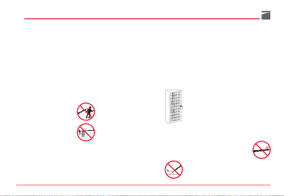
3. CUSTODIRE L’ARMA IN UN LUOGO SICURO
E NON ACCESSIBILE AI BAMBINI.
E’ vostro compito assicurarvi che i minori o altre
persone non autorizzate non abbiano accesso
all’arma. Per ridurre il rischio di incidenti ai
minori, scaricate l’arma, mettetela
sotto chiave e riponete le munizioni
in una separata sede e sempre sotto
chiave. Tenere sempre presente che i
dispositivi utilizzati per prevenire
incidenti - es. lucchetti per armi,
chiusure per camere di scoppio ecc.
non sono sufficienti ad impedire che
altri possano utilizzare l’arma o utilizzarla in modo improprio. La custodia dell’arma
in una cassetta di sicurezza apposita in acciaio
sarebbe l’ideale per ridurre la probabilità che
minori o persone non autorizzate possano utilizzare l’arma in modo improprio.
4. MAI SPARARE CONTRO SPECCHI D’ACQUA
O SU SUPERFICI DURE.
Sparare contro specchi d’acqua,
contro una roccia o altre superfici
dure aumenta il rischio di rimbalzi
o frammentazioni dei proiettili,
che può voler dire colpire bersagli non voluti o
limitrofi.
5. CONOSCERE LE CARATTERISTICHE DI SICUREZZA DELL’ARMA CHE STATE USANDO,
TENENDO PRESENTE CHE I DISPOSITIVI DI
SICUREZZA NON SOSTITUISCONO LE PROCEDURE DI UN MANEGGIO DELL’ARMA IN
SICUREZZA.
Non affidarsi esclusivamente ai dispositivi di
sicurezza al fine di prevenire incidenti. E’ di assoluta importanza che conosciate ed osserviate le
caratteristiche di sicurezza dell’arma che state
maneggiando; gli incidenti comunque, possono
essere maggiormente evitati se si seguono le procedure di un maneggio sicuro dell’arma, contenute nelle regole di sicurezza e all’interno di questo manuale.
Per familiarizzare ulteriormente con l’uso appropriato di questa o altre armi, si consiglia di seguire un corso sulla sicurezza delle armi tenuto da
un professionista del settore, esperto in tecniche
d’uso e procedure di sicurezza.
6. CONSERVARE L’ARMA IN MODO APPROPRIATO.
Custodire l’arma in modo che non si
accumuli sporco o polvere nelle
parti meccaniche. Seguendo le istruzioni contenute in questo manuale,
pulire e lubrificare l’arma dopo ogni
utilizzo per prevenire corrosione, danni alla
canna o accumulo di impurità che possano
impedire all’arma di funzionare in caso di necessità. Controllare sempre l’interno e la camera di
r
e
g
e
o
t
S
Page 10

scoppio prima di caricare l’arma per accertarsi
che siano puliti e privi di ostruzioni. Sparare
quando vi siano ostruzioni nella canna o nella
camera di scoppio può causare l’esplosione della
canna e ferire voi o altre persone vicine. Nel caso
si avverta un rumore anomalo durante lo sparo
smettere immediatamente di sparare, mettere la
sicura e scaricare l’arma.
Accertarsi che la camera e la canna siano libere
da eventuali ostruzioni, come ad es. un proiettile
bloccato all’interno della canna a causa di munizioni difettose o inadatte.
7. UTILIZZARE MUNIZIONI APPROPRIATE.
Utilizzare solo munizioni di fabbrica, nuove
munizioni realizzate secondo le seguenti specifiche industriali: CIP (Europa e altri paesi),
SAAMI® (U.S.A.). Assicurarsi che i proiettili
siano del calibro o del tipo adatti all’arma utilizzata. Il calibro dell’arma è contrassegnato chiaramente sulla canna del fucile o sul carrello o
canna della pistola.
L’utilizzo di munizioni ricaricate o ricostruite
può aumentare la probabilità di pressione eccessiva sulla cartuccia, esplosione del fondello o
altri difetti delle munizioni che possano causare
danni all’arma e ferire voi o altre persone vicine.
8. INDOSSARE SEMPRE OCCHIALI DI PROTEZIONE E TAPPI PER LE ORECCHIE QUANDO
SI SPARA.
La probabilità che gas, polvere da
sparo o frammenti metallici colpiscano e feriscano il tiratore mentre
spara, è remota, ma nell’evenienza
che questo succeda, i danni possono essere
gravi, inclusa la possibilità di perdere la vista.
Quando spara, il tiratore deve sempre indossare
occhiali di protezione ad alta resistenza. Tappi
per le orecchie o altri tipi di protezione di alta
qualità aiutano a ridurre il rischio di danni provocati dallo sparo.
9. NON ARRAMPICARSI MAI SU ALBERI, RECINZIONI O OSTACOLI CON L’ARMA CARICA.
Aprire e svuotare la camera dell’arma e mettere la sicura prima di
arrampicarsi o scendere da alberi o
prima di scavalcare recinti o saltare
fossati o altri ostacoli. Non tirare o
spingere l’arma verso se stessi o verso un’altra
persona. Scaricare sempre l’arma e controllare
visivamente e fisicamente che il serbatoio, il
meccanismo di ricarica e la camera siano scarichi e che l’arma abbia l’otturatore aperto prima
di darla in mano ad un’altra persona. Non prendere mai un’arma da un’altra persona a meno
che non sia scarica, controllata fisicamente e
visivamente per accertarsi che sia effettivamente
scarica e comunque prendere l'arma solo se
aperta.
10. EVITARE L’USO DI BEVANDE ALCOLICHE O
MEDICINALI CHE POSSANO DIMINUIRE I
RIFLESSI E L’AUTOCONTROLLO MENTRE SI
SPARA.
Non bere quando si spara. Se si
assumono medicinali che possano
diminuire i riflessi o l’autocontrollo,
non maneggiare armi mentre si è
sotto l’effetto del medicinale.
11. NON TRASPORTARE MAI UN’ARMA CARICA.
Scaricare sempre l’arma prima di
riporla in un veicolo (camera e serbatoio vuoti). Cacciatori e tiratori
devono caricare l’arma una volta
giunti a destinazione, e solo quando
sono sul punto di sparare. Se si detiene un’arma
per difesa personale, lasciare la camera scarica
riduce la possibilità di uno sparo involontario.
12. AVVERTENZE SULL’ESPOSIZIONE AL PIOMBO.
Scaricare l’arma in aree con scarsa ventilazione,
pulire armi o maneggiare munizioni può comportare una esposizione al piombo e ad altre
sostanze che possono causare danni alla respirazione, danni all’apparato riproduttivo ed altri
gravi danni fisici. Sostare sempre in aree con
buona ventilazione. Lavare accuratamente le
mani dopo l’esposizione.
AVVERTENZA: è VOSTRA responsabilità cono-
scere e rispettare le leggi locali e statali che regolamentano il commercio, il trasporto e l’uso delle
armi nel vostro paese.
AVVERTENZA: questa arma può togliere la vita a
voi e agli altri! Siate sempre estremamente attenti nel maneggiare l’arma. Un incidente è quasi
sempre la conseguenza del mancato rispetto
delle norme di sicurezza dell’arma.
9
Page 11
10
Presentazione
La Benelli Armi è lieta di presentare il nuovo
Raffaello, con l’introduzione di tecnologie esclusive e con un significativo restyling estetico che
permettono alla nostra famiglia più importante
di emergere come fucili classici, ma con un
moderno cuore tecnologico.
Grazie al costante impegno del nostro Centro
Studi e Ricerche, il nuovo Raffaello gode di tutte
le peculiarità dei prodotti Benelli unite all’eccellente innovazione del Comfort Progressive.
L’unico sistema anti-rinculo applicato ai calci in
legno che, in base alle cartucce utilizzate, si attiva in maniera più o meno forte per attutire progressivamente il rinculo e crea insieme al nasello il sistema di Full Comfort globale.
Una nuova sfida, un fucile sicuramente prezioso
che va ad arricchire la già vasta gamma di prodotti Benelli.
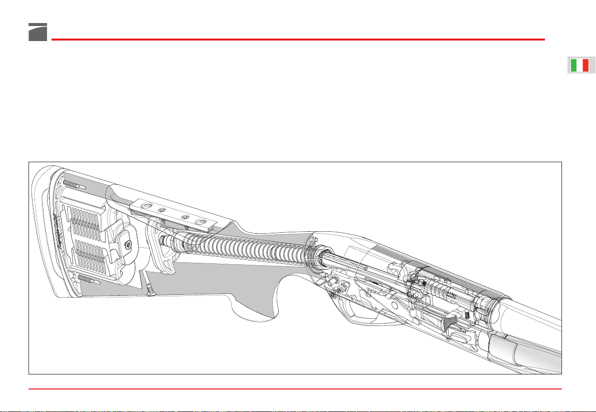
Funzionamento
I nuovi fucili semi-automatici “Benelli” sono
basati sullo stesso principio di funzionamento
inerziale, a canna fissa, utilizzante l’energia cinetica di rinculo delI’arma, che ancora oggi rappresenta la novità tecnica più rilevante e geniale
delle nostre armi.
Come noto, questo sistema non necessita di
presa di gas né tantomeno del rinculo della
canna ma, per il suo funzionamento, si avvale di
una molla interposta liberamente fra testa di
chiusura ed otturatore.
Durante lo sparo, per reazione al rinculo del fucile, I’otturatore (inerte) compie un avanzamento
proporzionato alla potenza della cartuccia di circa
4 mm, comprimendo la molla; questa, ultimato di
comprimersi, si distende facendo arretrare tutto il
gruppo otturatore e permettendo così l’estrazione
del bossolo ed il ricaricamento dell’arma che
avvengono secondo il sistema tradizionale.
Il carico della molla è opportunamente tarato sia
per creare un ritardo all’apertura sia per regolare,
senza necessità di freno, le diverse pressioni prodotte da cartucce di varia potenza.
A questo principio di funzionamento è stata abbinata una testa di chiusura rotante di forma semplice e robusta che con soli due denti di chiusura realizza una perfetta chiusura assiale in culatta capace di sopportare le pressioni in canna sviluppate dalla cartuccia.
La nuova gamma si avvale di un sistema di alimentazione appositamente studiato per:
- consentire il passaggio manuale delle cartucce
in canna dal tubo serbatoio per un facile e
rapido cambio della munizione in canna;
- assicurare una alimentazione ancor più veloce
e sicura nel riarmo automatico;
- verificare rapidamente se l’arma ha il cane
armato ed è pronta per il tiro.
Il nuovo sistema di alimentazione si avvale infatti di una particolare leva discesa cartuccia sporgente per un tratto dal piano inferiore della carcassa in posizione facilmente accessibile al dito
che preme il grilletto.
Al momento dello sparo la molla del cane fa ruotare verticalmente la leva discesa cartuccia, disimpegnandola dalla leva fermo cartuccia; quest’ultima, per effetto della sua molla richiamo,
ruota in senso orario permettendo con ciò l’uscita di una cartuccia dal serbatoio.
Tale cartuccia nel posizionarsi sul cucchiaio elevatore preme contro la leva fermo cartuccia
facendola ruotare in senso inverso ed impedendo
con ciò l’uscita di una seconda cartuccia.
Il cucchiaio elevatore, comandato dalI’otturatore, sale automaticamente e porta la cartuccia
in posizione idonea alI’incameramento.
Nel frattempo la molla del cane, già ricompressa
in posizione di armamento, ha lasciato libera la
leva discesa cartuccia di riprendere la sua posizione di riposo: in tal modo la leva fermo cartuccia è obbligata a trattenere definitivamente le cartucce ancora in serbatoio fino a quando non
verrà sparato un nuovo colpo.
La leva discesa cartuccia, ha ben visibile sulla
parte che sporge dal piano inferiore della carcassa un punto rosso. Quando questo è visibile,
I’arma ha il cane armato ed è pronta a far fuoco;
in caso contrario, I’arma ha il cane disarmato.
I nuovi fucili, come tutti gli automatici Benelli,
LEGENDA COLORI FRECCE
colore descrizione
rosso sequenza di smontaggio
verde sequenza di montaggio
blu indicazione
giallo azionamento
Page 12
utilizzano l’energia di rinculo dell’arma per ogni
suo movimento automatico; vengono così eliminati sia gli inconvenienti dei sistemi a canna rinculante (vibrazione della canna durante lo sparo,
necessità di freno di regolazione per cartucce
potenti, ecc.) sia gli inconvenienti del sistema a
sottrazione di gas, (necessità di pulizia della
presa di gas, perdita di potenza nella velocità iniziale della carica di piombo e ripercussione
negativa sulla conformazione in profondità della
rosata e possibili difetti in condizioni atmosferi-
che avverse), realizzando un’arma moderna e
pienamente affidabile.
I nuovi semi-automatici Benelli, per l’alto grado
di perfezionamento raggiunto, sono in grado di
funzionare con una vastissima gamma di cartucce; l’originalità del sistema di funzionamento
inerziale richiede comunque alla cartuccia un
minimo di energia cinetica necessaria per un
completo automatismo di riarmo determinato dal
rinculo dell’arma stessa.
Approfondite esperienze di laboratorio balistico
e di prove pratiche, ci consentono di fissare i
parametri per il corretto funzionamento dell'arma, individuando in 200 kgm il valore minimo
dell'energia cinetica sviluppata dalla cartuccia
cal. 12 (valore misurato su canna manometrica a
1 m dalla volata).
AVVERTENZA: il corretto funzionamento dell’ar-
ma, con il valore minimo dell’energia cinetica
indicata, è garantito per un’arma di peso MASSIMO complessivo pari a 3,150 kg.
11
Page 13
12
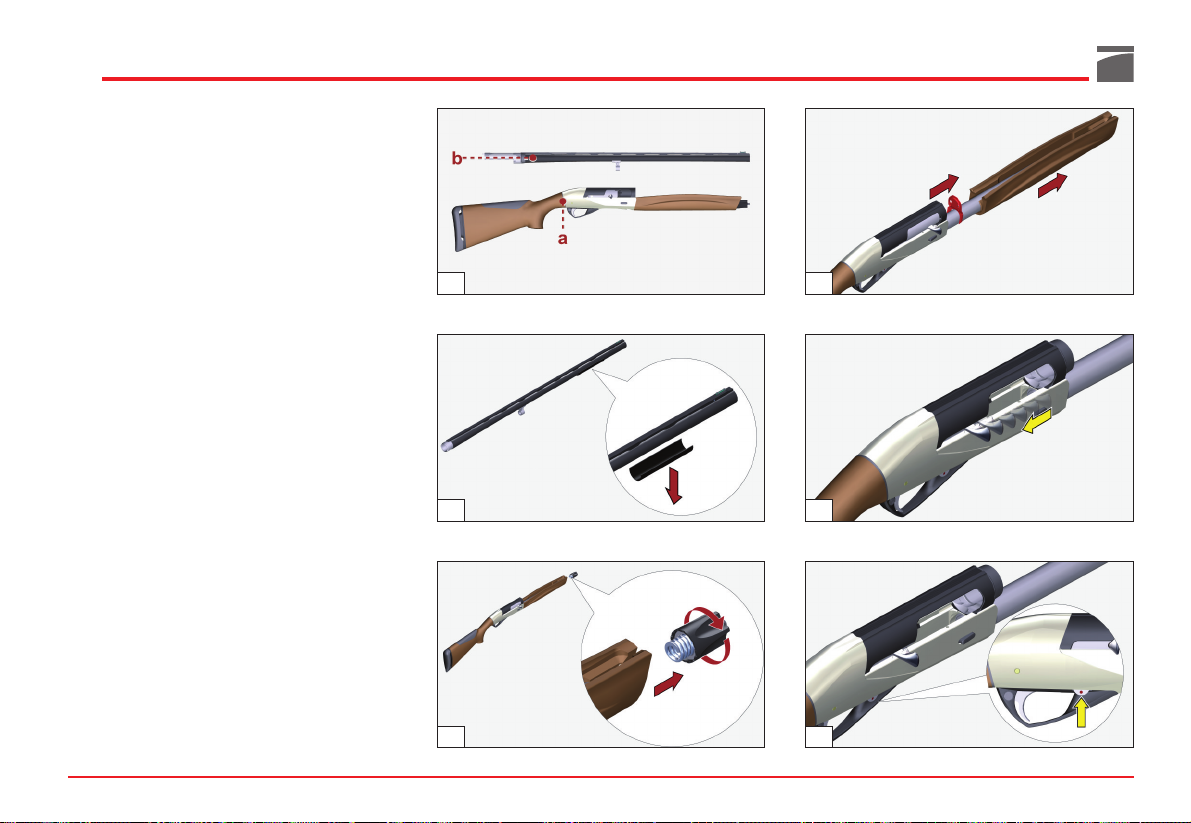
Montaggio
(da fucile imballato)
Componenti confezione (fig. 1):
a) gruppo calcio-carcassa-otturatore-astina
b) gruppo canna-culatta
AVVERTENZA: ricordarsi di rimuovere il copri-
canna di plastica prima di utilizzare il fucile
(fig. 2).
Procedura di montaggio
1) Svitare il cappellotto fissaggio astina (fig. 3).
2) Sfilare l'astina e rimuovere il piastrino di
imballo arma (fig. 4).
3) Impugnare il gruppo calcio-carcassa-ottura-
tore e, agendo sulla manetta, portare l'otturatore in posizione di apertura (fino ad
agganciamento avvenuto) (fig. 5).
AVVERTENZA: se l'otturatore non rimane
agganciato, agire sulla leva discesa cartuccia,
nel senso indicato dalla freccia, e ripetere l'operazione (fig. 6).
Durante queste operazioni l'otturatore deve
essere completamente assemblato e alloggiato
nella carcassa, rimanendo sempre in posizione
di apertura (tutto indietro).
4) Mantenere fermo il fodero sulla carcassa e
prendere il gruppo canna-culatta.
3
2
1
6
4
5
Page 14
5) Infilare il prolungamento della culatta sulla
carcassa, accertandosi che l'anello guida
canna calzi correttamente il tubo serbatoio
(fig. 7).
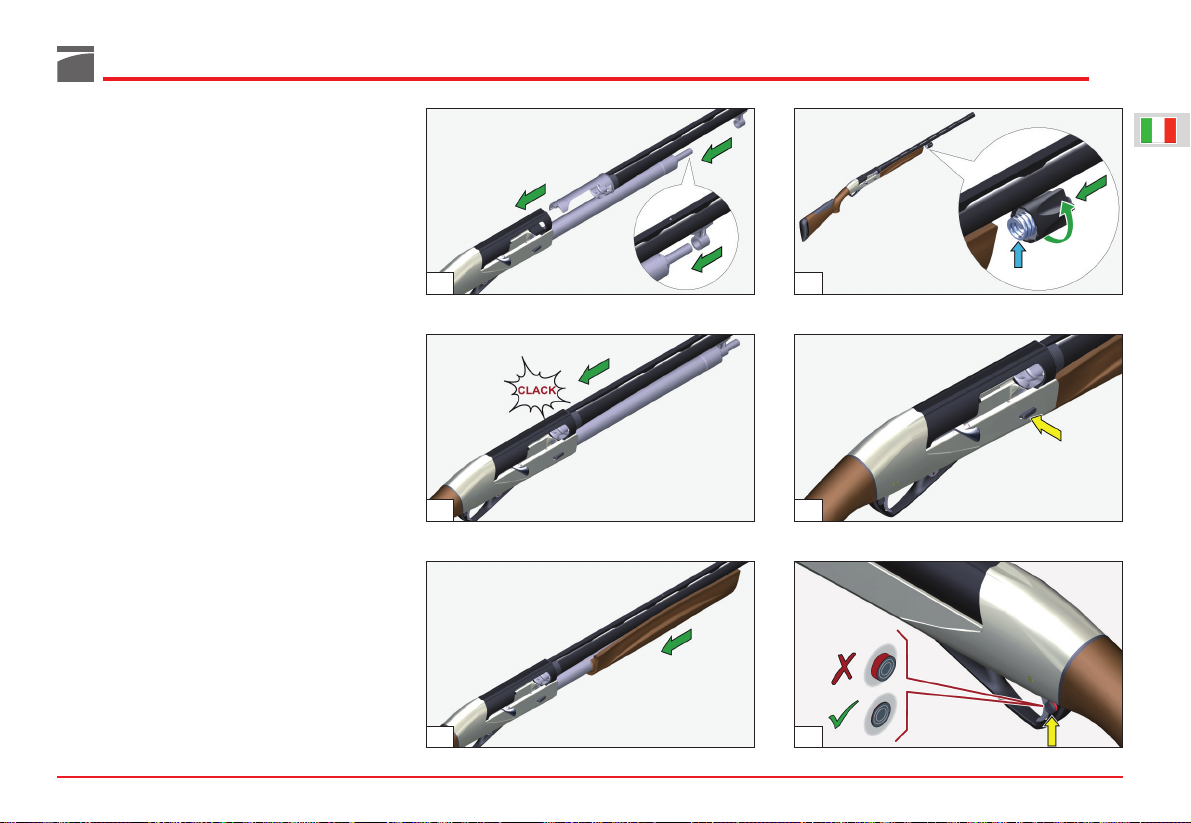
6) Spingere a fondo sulla canna fino alla posizione di fine corsa (fig. 8) chiaramente avvertibile sia dalla mano che preme sia dal suono
metallico che si produce al momento dell'arresto.
ATTENZIONE: assicurarsi sempre che il prolun-
gamento della culatta non batta contro la testa di
chiusura dell’otturatore ma si infili fra fodero e
testa di chiusura stessa.
7) Infilare l'astina sul tubo serbatoio (fig. 9).
8) Avvitare il cappellotto di fissaggio, sull'estremità del tubo serbatoio, serrandolo a fondo
per bloccare perfettamente canna e astina
contro la carcassa (fig. 10).
ATTENZIONE: prima di bloccare canna ed asti-
na contro la carcassa, accertarsi sempre che la
molla del cappellotto di fissaggio sia inserita nel
cappellotto stesso (fig. 10): la mancanza della
molla non consente un regolare bloccaggio della
canna, con conseguenti danni all'arma.
9) Chiudere l'otturatore, premendo il bottone
della leva comando elevatore (fig. 11).
Sicura del fucile
Spingere il bottone di sicura a traversino posto
sulla guardia: a sicura inserita non si deve vede-
re l'anello rosso indicante la posizione di sparo
(fig. 12).
13
7
8
9
10
12
11
Page 15
14
Caricamento
Prima di effettuare qualunque tipo di intervento
sul fucile, accertarsi sempre che camera di scoppio e serbatoio siano completamente vuoti!
(Leggere attentamente le istruzioni di caricamento e scaricamento dell’arma).
Il serbatoio di alimentazione è predisposto per
contenere 1, 2, 3 oppure 4 cartucce (a seconda
della versione e delle norme vigenti).
Compresa la cartuccia in canna, quindi, la capacità di fuoco del fucile è di 2, 3, 4 oppure 5 colpi.
Procedura di caricamento
ATTENZIONE: l'arma deve essere in sicura (vedi
“Sicura del fucile”) e con cane armato (per consentire alla leva fermo cartuccia di bloccare le
cartucce introdotte nel serbatoio).
AVVERTENZA: per maggior sicurezza, verificare
che l'arma sia scarica aprendo l'otturatore.
Riportare poi l'otturatore in chiusura.
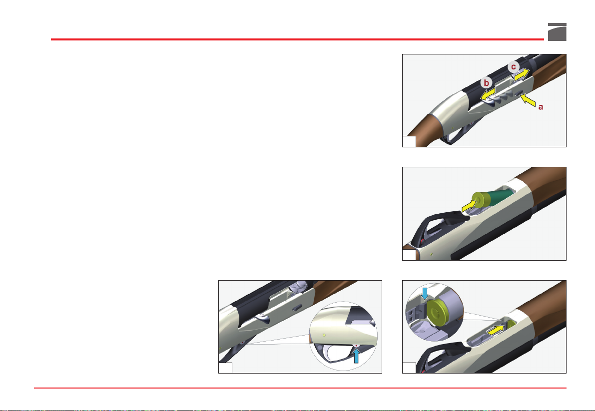
1) La leva discesa cartuccia deve avere il punto
rosso ben visibile (avviso cane armato) (fig.
13). Se necessario, portarla in tale posizione
premendo il bottone leva comando elevatore
(a), aprendo a mano l'otturatore (b) e riportandolo poi in posizione di chiusura (c) (fig.
14).
2) Con otturatore chiuso e cane armato, rovesciare l'arma, orientando la canna verso il
basso.
3) Infilare una cartuccia a fondo nel serbatoio
(fig. 15): la leva di arresto deve agganciare la
cartuccia automaticamente, trattenendola
(fig. 16). Ripetere l'operazione sino al completo caricamento del serbatoio.
ATTENZIONE: il caricamento del serbatoio deve
essere effettuato con il cane armato per consentire alla leva fermo cartuccia di bloccare le cartucce che si introducono nel serbatoio stesso.
A questo punto il fucile non può ancora sparare
se prima non si introduce una cartuccia in
canna, operando secondo una delle due alternative indicate:
13
15
16
14
Page 16
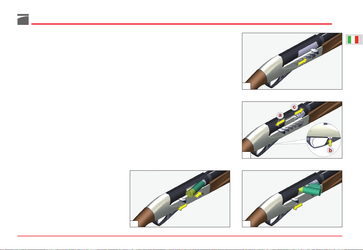
Soluzione diretta (figg. 17-18):
1) Aprire l'otturatore e trattenerlo in tale posi-
zione mentre si introduce una cartuccia in
canna attraverso la finestra di espulsione bossolo.
2) Rilasciare l'otturatore che, scorrendo in
avanti, incamera la cartuccia e si arresta in
posizione di chiusura.
Soluzione indiretta (fig. 19):
1) Aprire l'otturatore (a) e trattenerlo in tale
posizione mentre si preme la leva discesa
cartuccia (b), consentendo alla prima cartuccia di scendere sull’elevatore.
2) Rilasciare l'otturatore (c) che, scorrendo in
avanti incamera la cartuccia e si arresta in
posizione di chiusura.
AVVERTENZA: avvalendosi della soluzione di
caricamento “indiretta” si riduce di un colpo la
quantità di cartucce nel serbatoio. E' possibile
l'inserimento - come prima descritto - di una
ulteriore cartuccia per riempirlo completamente.
ATTENZIONE: durante queste operazioni - anche
se l'arma è in sicura (vedi “Sicura del fucile”) - è
opportuno orientare la canna in direzione di sicu-
ra prudenza.
A questo punto il fucile è carico: portando la
sicura in posizione di sparo (anello rosso visibi-
le), l'arma è pronta per sparare.
AVVERTENZA: all'inizio dell'uso (fucile nuovo)
può essere necessario un breve periodo di rodaggio prima che l'arma funzioni perfettamente an-
che con cariche leggere. In presenza di problemi
di funzionamento, è opportuno sparare a titolo di
rodaggio tre o quattro scatole di cartucce con
carica standard.
Sostituzione cartuccia
(Operazione da effettuarsi con fucile in sicura vedi “Sicura del fucile” - e canna orientata in
direzione di sicura prudenza)
Per sostituire una cartuccia già incamerata si
possono seguire due procedure:
- introduzione manuale della nuova cartuccia;
- azionamento della leva discesa cartuccia.
Introduzione manuale della cartuccia (sostituzione con cartuccia non proveniente dal serbatoio)
1) Appoggiare il calcio sull’anca ed aprire
manualmente l’otturatore tirando la manetta:
la cartuccia in camera viene estratta ed espulsa dall’arma (fig. 20).
15
17
18
19
20
Page 17
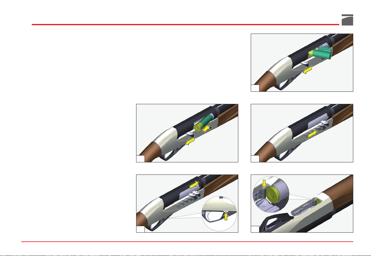
16
2) Introdurre, anche parzialmente in canna, la
nuova cartuccia attraverso la finestra di
espulsione (fig. 21) e lasciare poi libera la
manetta per richiudere l’otturatore.
Azionamento della leva discesa cartuccia (sostituzione con cartuccia proveniente dal serbatoio)
1) Appoggiare il calcio sull’anca ed aprire
manualmente l’otturatore tirando la manetta:
la cartuccia in camera viene estratta ed espulsa dall’arma (fig. 20).
2) Premere la leva discesa cartuccia (fig. 22);
quindi lasciar libera la manetta per richiudere l’otturatore: si otterrà in tal modo il passaggio rapido della cartuccia dal serbatoio alla
camera di scoppio.
Scaricamento dell’arma
(Operazione da effettuarsi con fucile in sicura vedi “Sicura del fucile” - e canna orientata in
direzione di sicura prudenza)
Per scaricare il fucile, agire come segue:
1) Aprire l'otturatore: la cartuccia incamerata
viene estratta ed espulsa dall'arma (fig. 23).
2) Chiudere l'otturatore, accompagnando la
manetta con la mano (fig. 24).
3) Capovolgere l'arma e - spingendo l'elevatore
all'interno - far pressione con l'indice della
mano nella parte anteriore della leva fermo
cartuccia (fig. 25): la prima cartuccia nel serbatoio uscirà. Si deve ripetere tale operazione
per ciascuna cartuccia che si vuol estrarre dal
serbatoio.
AVVERTENZA: l'arma può essere scaricata
anche ripetendo più volte l'operazione descritta
al punto “Azionamento della leva discesa cartuccia” del capitolo "Sostituzione cartuccia".
23
25
2421
22
Page 18
Inconvenienti e rimedi
Prima di effettuare qualunque tipo di intervento
sul fucile, accertarsi sempre che camera di scoppio e serbatoio siano completamente vuoti!
(Leggere attentamente le istruzioni di caricamento e scaricamento dell’arma).
Se il fucile non spara
1) Controllare la sicura: se inserita, spingere il
pulsante a traversino nella posizione di fuoco.
2) Controllare che la cartuccia sia in canna. Se
necessario, introdurre una cartuccia seguendo
le istruzioni relative al caricamento (pag. 14).
3) Controllare il meccanismo di sparo. Se
necessario, procedere alla sua pulizia e lubrificazione.
Cappellotto fissaggio astina
Durante il montaggio accertarsi che il cappellotto fissaggio astina sia completo di molla e, spe-
cialmente dopo i primi colpi, che sia ben avvitato, in modo da mantenere la canna completa-
mente bloccata alla carcassa.
Munizionamento
Il fucile Benelli utilizza per il suo funzionamento
l'energia cinetica del rinculo dell'arma.
Utilizzare sempre cartucce che garantiscano un
rinculo sufficiente per il completo automatismo
di riarmo.
AVVERTENZA: all'inizio dell'uso (fucile nuovo)
può essere necessario un breve periodo di rodaggio prima che l'arma funzioni perfettamente
anche con cariche leggere. In presenza di problemi di funzionamento, è opportuno sparare a titolo di rodaggio tre o quattro scatole di cartucce
con carica standard.
Munizioni da usare
Il funzionamento dell’arma è garantito con cartucce di lunghezza massima 58 mm (camera 2”
3/4 - 70 mm), o 66 mm (camera 3” - 76 mm), a
chiusura orlata o stellare e caricate con pallini
sia di piombo che di acciaio.
Benelli consiglia l’utilizzo di munizioni caricate
a pallini per le canne con bindella e le munizioni a palla per le canne slug.
Questa indicazione non è obbligatoria ma assicura il raggiungimento delle migliori prestazioni.
ATTENZIONE: non usare mai cartucce con bosso-
lo la cui lunghezza superi quella della camera di
scoppio!
La mancata osservanza di questa regola comporta gravi conseguenze sia per il tiratore che
per l'arma.
I fucili Benelli non richiedono regolazione alcuna per qualsiasi munizionamento impiegato.
Utilizzare sempre cartucce che garantiscano un
rinculo sufficiente al completo riarmo dell'arma.
Tutti i fucili Benelli sono sottoposti alla prova
forzata di 1370 bar presso il Banco Nazionale di
Prova di Gardone Valtrompia (Brescia).
Manutenzione
Prima di effettuare qualunque tipo di intervento
sul fucile, accertarsi sempre che camera di scoppio e serbatoio siano completamente vuoti!
(Leggere attentamente le istruzioni di caricamento e scaricamento dell’arma).
Per l'estrema semplicità costruttiva e per l'accurata scelta dei materiali, l’automatico Benelli non
richiede particolari interventi di manutenzione.
Si consiglia quindi di effettuare:
1) la normale pulizia della canna dopo l'uso;
2) eliminare con una periodica pulizia e lubrifi-
cazione gli eventuali residui di polvere (o
materiali estranei) dal gruppo di sparo (cane,
grilletto, ecc.);
3) smontare, pulire e lubrificare il gruppo ottu-
ratore, che può essere soggetto parimenti ai
residui sopra citati;
4) per la buona conservazione dell'arma, si consiglia di tenere lubrificate le parti soggette
agli agenti atmosferici.
17
26
Page 19
18
NB: tutte le canne sono cromate internamente.
NOTA: quando si esegue la pulizia di canne con
strozzatori interni, lasciare lo strozzatore installato, al fine di evitare l’accumulo di residui nel
filetti di attacco dello strozzatore interno alla
canna.
Per una corretta manutenzione dell’arma, utilizzare il set di pulizia Benelli (non in dotazione).
Per la lubrificazione e protezione delle parti
meccaniche (carcassa, otturatore e canna) si
consiglia l’utilizzo dell’olio Benelli (fig. 26).
Per la pulizia degli altri componenti dell’arma
(calcio e astina in legno, in tecnopolimero e
camouflage o verniciati), Benelli suggerisce l’utilizzo di prodotti specifici, evitando che queste
parti vengano a contatto con olii contenenti sol-
venti o sostanze chimiche in genere, che potrebbero provocare distacco o variazione delle
superfici.
Smontaggio dell’arma
(per manutenzione e pulizia)
Prima di effettuare qualunque tipo di intervento
sul fucile, accertarsi sempre che camera di scoppio, elevatore e serbatoio siano completamente
vuoti!
(Leggere attentamente le istruzioni di caricamento e scaricamento dell'arma).
AVVERTENZA
(sui modelli dove è disponibile il sistema
ShellView)
Anche se il sistema “ShellView” consente di
vedere se il serbatoio dell’arma è scarico, questo
non implica che l’arma sia completamente scarica. Controllare sempre “fisicamente e visivamente” serbatoio e camera di scoppio dell’arma
per verificare che sia completamente scarica
(fig. 27). Seguire sempre e scrupolosamente
tutte le Norme di Sicurezza riportate nel manuale d’uso e manutenzione.
a ShellView Benelli nell’astina
b cartucce ancora in serbatoio
c cartuccia assente
28
27
29
30
Page 20
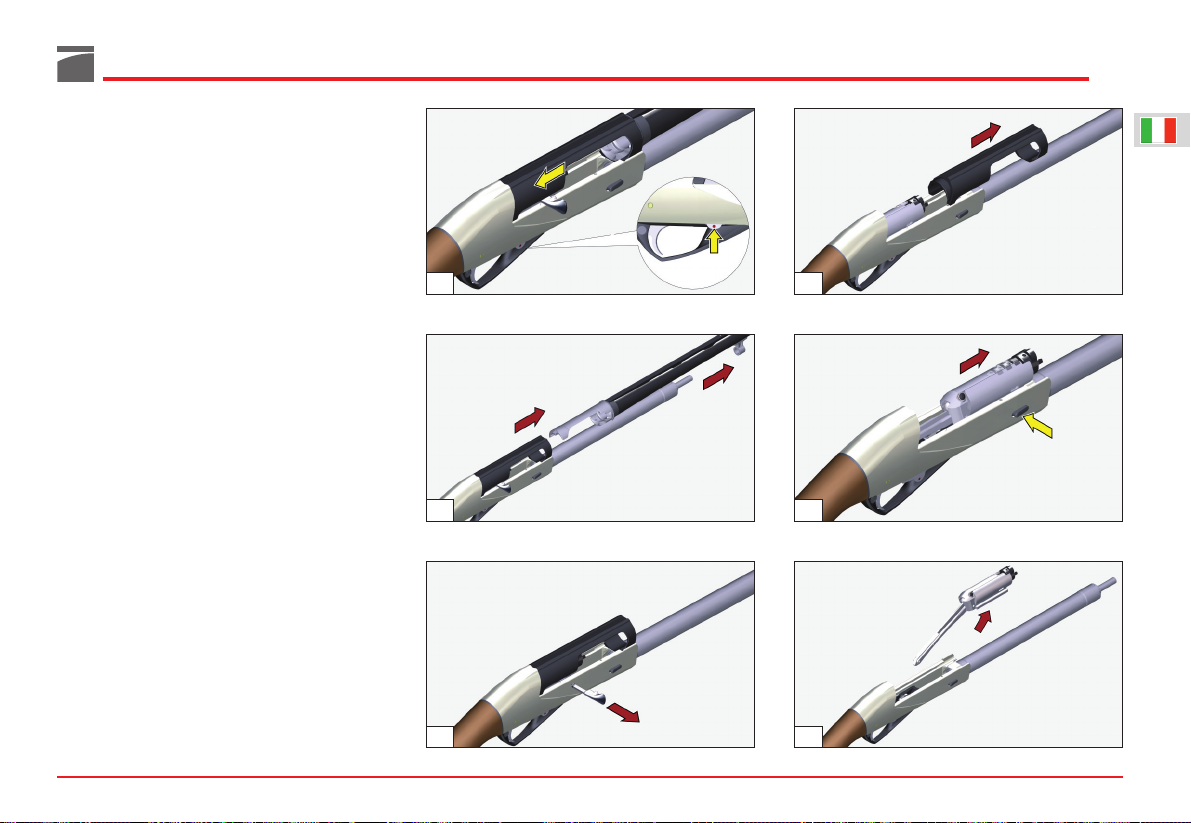
Procedura di smontaggio
1) Svitare il cappellotto di fissaggio astina e sfilare l'astina verso l'avanti, lungo il tubo serbatoio (figg. 28-29).
2) Impugnare il fucile con una mano e, con l'altra, aprire l'otturatore (fig. 30). Se l'otturatore
non rimane aperto, agire sulla leva discesa
cartuccia, come indicato dalla freccia e ripetere l'operazione (fig. 31).
3) Appoggiando il calcio sull'anca, prendere il
fucile con una mano in maniera da mantenere fermo il fodero sulla carcassa e, con l’altra,
tirando in avanti, sfilare il gruppo canna-
culatta dalla carcassa (fig. 32).
4) Togliere la manetta di armamento con uno
strappo deciso (fig. 33).
5) Separare il fodero dalla carcassa sfilandolo in
avanti dal gruppo otturatore (fig. 34).
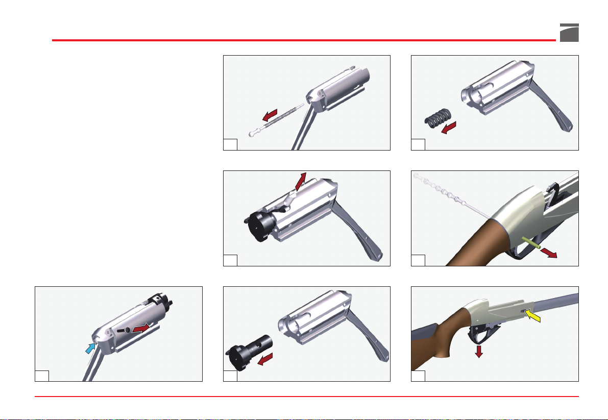
6) Trattenendo con una mano il gruppo ottura-
tore (fig. 35) in maniera da contrastare la
spinta della molla della biella, premere l’apposito bottone comando elevatore ed
accompagnare l’otturatore in avanti fino a
quando non è più spinto dalla molla biella.
7) Estrarre il gruppo otturatore dalla carcassa
facendolo scorrere in avanti sulle sue guide di
alloggio (fig. 36).
19
31 34
33
32
36
35
Page 21
20
8) Sfilare il perno arresto percussore dal gruppo otturatore, avendo cura di trattenere il
percussore e la sua molla di richiamo (fig.
37).
9) Estrarre dall’otturatore il percussore con la
sua molla di richiamo (fig. 38).
10) Togliere il perno rotazione testa di chiusura
sfilandolo dalla sua sede (fig. 39).
11) Sfilare la testa di chiusura dall’otturatore (fig.
40).
12) Togliere la molla di rinculo otturatore dalla
sua sede (fig. 41).
13) Sfilare dal gruppo calcio-carcassa la spina
arresto guardia, spingendola da destra o da
sinistra con la punta del percussore stesso o
con un punteruolo adatto (fig. 42).
14) Premere il bottone comando elevatore e sfi-
lare in avanti il gruppo guardia (fig. 43).
Il fucile è completamente smontato; le parti che
necessitano un’accurata verifica e pulizia sono
ora smontate.
38
40
39
41
43
42
37
Page 22
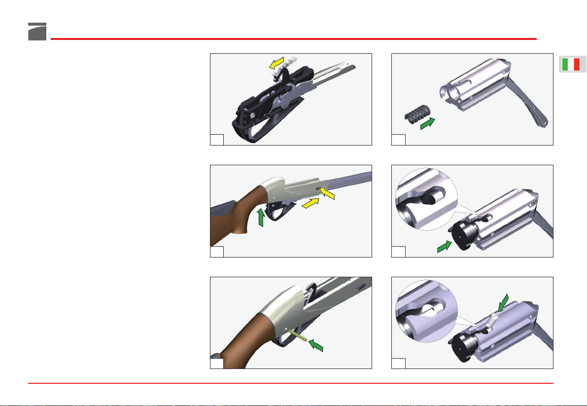
Montaggio dell’arma
Per un corretto montaggio dell'arma, procedere
nel seguente ordine:
1) Armare il cane (fig. 44), impugnare il gruppo
calcio-carcassa, premere il bottone comando
elevatore ed inserire contemporaneamente il
gruppo guardia completo (a cane armato)
nella carcassa, riportandolo a battuta sulla
parte anteriore (fig. 45).
2) Infilare da destra o da sinistra la spina arresto
guardia fermandola quando si trova completamente inserita nella carcassa (fig. 46).
3) Infilare la molla rinculo otturatore nella pro-
pria sede (fig. 47).
ATTENZIONE: accertarsi di collocare sempre la
molla di rinculo dell'otturatore tra testa di chiu-
sura ed otturatore stesso, per evitare che - nella
fase di chiusura - possa partire il colpo.
4) Infilare la testa di chiusura nell’otturatore,
avendo cura che il foro sul suo gambo colli-
mi con l’asola dell’otturatore stesso (fig. 48).
AVVERTENZA: i piani inclinati ricavati sul
gambo della testa di chiusura non devono essere
visibili a pezzo montato.
5) Infilare il perno rotazione testa di chiusura
nel foro ricavato sul gambo della testa di
chiusura, facendolo passare attraverso l’asola
dell’otturatore (fig. 49).
ATTENZIONE: la linea di riferimento marcata
sull'estremità del perno deve essere in vista e
allineata con l'asse longitudinale del gruppo
otturatore (fig. 49).
21
44
46
45 48
49
47
Page 23
22
6) Inserire il percussore con la sua molla nel
foro nell’otturatore (fig. 50).
ATTENZIONE: accertarsi di aver montato sem-
pre la molla del percussore.
7) Inserire il perno arresto percussore nel suo
foro, in modo che blocchi il percussore (fig.
51).
8) Impugnare il gruppo calcio-carcassa e,
tenendolo in posizione quasi orizzontale,
inserire il gruppo otturatore nelle guide
della carcassa (fig. 52).
AVVERTENZA: la biella otturatore, passando
sopra la guardia, deve posizionarsi sul perno
guida molla biella, all'interno della carcassa a
montaggio completato (fig. 52).
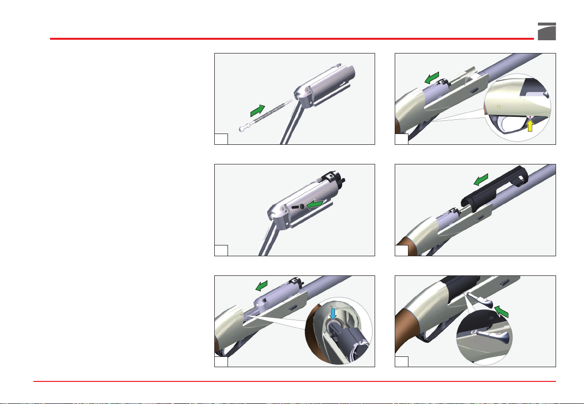
9) Portare l'otturatore in posizione di apertura,
tirando dal piano frontale della testa di chiusura (fig. 53); qualora l’otturatore non rimanga aperto, premere la leva discesa cartuccia
nel senso indicato dalla freccia e ripetere l’operazione.
10) Prendere il fodero ed accostarlo alla car-
cassa in posizione leggermente avanzata
rispetto all’otturatore (fig. 54).
11) Mantenendo il fodero aderente alla carcas-
sa, arretrarlo e infilarlo sull’otturatore fino a
completo montaggio in posizione di battuta
posteriore sulla carcassa.
12) Inserire la manetta sul foro di sede del-
l’otturatore premendo a fondo (fig. 55).
13) Completare il montaggio dell’arma ripeten-
do tutte le operazioni di montaggio da fucile imballato descritte a pag. 13 (figg. 7-8-910-11).
50
51
53
54
5552
Page 24
ACCESSORI E REGOLAZIONI
Variazione e deviazione piega
Prima di effettuare qualunque tipo di intervento
sul fucile, accertarsi sempre che camera di scoppio e serbatoio siano completamente vuoti!
(Leggere attentamente le istruzioni di caricamento e scaricamento dell’arma).
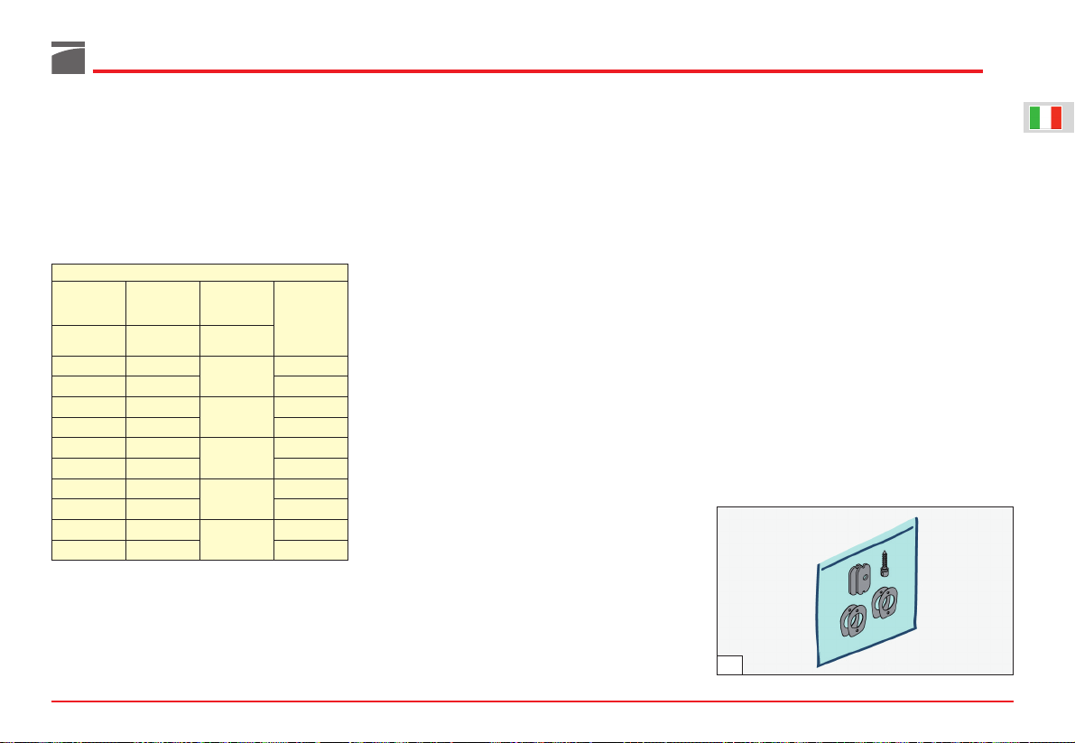
Il fucile è dotato di un “kit variazione piega”
(fig. 56), che permette di variare la configurazione in cui viene fornita l’arma.
Il kit è formato da piastrini serraggio calcio (in
acciaio) e spessori variazione piega (in plastica),
oltre che dal perno per fissaggio maglietta portabretella (per i calci in legno).
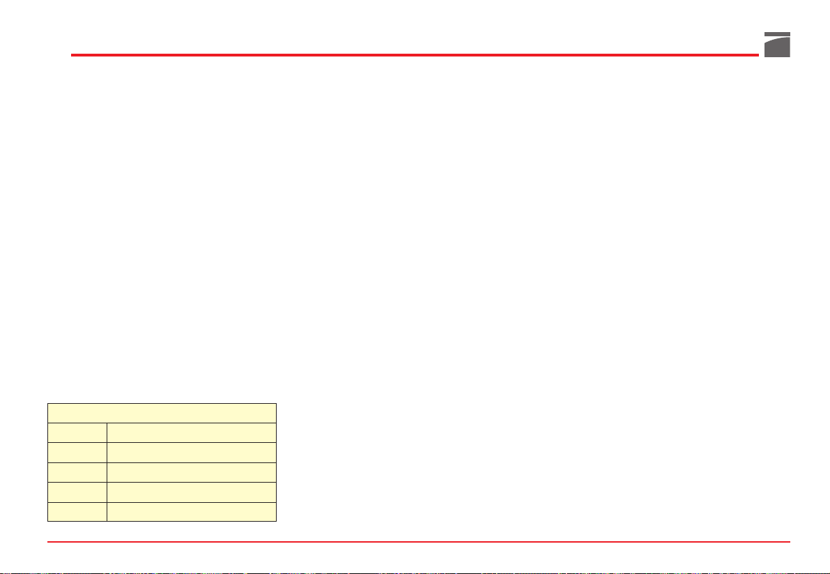
Il kit permette di ottenere cinque diverse configurazioni di piega (indicate in tabella) e due
diverse deviazioni (destro o sinistro). Ciascun
elemento è marcato con la lettera di piega e
deviazione corrispondente.
Stabilite se la piega del calcio si adatta perfettamente alla vostra persona, o se sia troppo basso
oppure troppo alto.
Se troppo basso (piega troppo elevata), selezionare il set di regolazione precedente in ordine
alfabetico (es: se lo spessore montato in fabbrica
è marcato “C”, passare a quello marcato “B” ed
al corrispondente piastrino di serraggio calcio).
Il procedimento di sostituzione è il seguente
(fig. 57):
1) Svitare le due viti di fissaggio e staccare il
calciolo “1” (cacciavite a croce).
AVVERTENZA: per non danneggiare i calcioli,
spalmare la punta del cacciavite con vaselina o
grasso.
2) Svitare le due viti di fissaggio ed estrarre il
kit comfort dal calcio “2” (cacciavite a
croce).
Istruzioni per l’abbinamento: le lettere identificano i kit
piastrino variazione piega - piastrino di serraggio. Per una
corretta piega abbinare sempre piastrini aventi stessa let-
tera, es: C - CDX – per piega 60-DX oppure C - CSX – per
piega 60-SX.
DX = Destro
SX = Sinistro
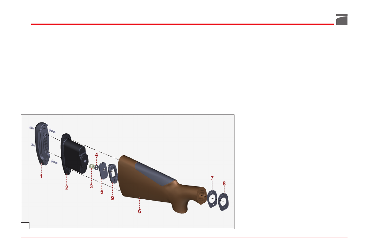
3) Svitare il dado di bloccaggio calcio “3”
(chiave esagonale da 13 mm).
4) Sfilare dal tubo guida molla biella il dado
“3”, la rondella elastica “4”, il piastrino di
serraggio calcio “5”, il calcio “6”, lo spessore deviazione “7” e lo spessore piega “8”.
AVVERTENZA: se il distanziale calcio “9” non
rimane all’interno del calcio, rimontarlo con la
sede del piastrino “5” rivolta verso il calciolo.
5) Montare sul tubo guida molla biella lo spes-
sore piega selezionato “8”, con il lato stampigliatura lettera rivolto verso il calcio.
6) Rimontare lo spessore deviazione “7”, con il
lato stampigliatura lettera prescelto (DX o
SX) rivolto verso il calcio.
7) Posizionare la canna verso il pavimento e
montare il calcio, infilare il corrispondente
piastrino di serraggio “5” nel calcio stesso,
con il lato stampigliatura lettera prescelto
rivolto verso il calciolo.
23
56
TABELLA VARIAZIONE PIEGA
Spessore Piastrino Spessore
deviazione serraggio calcio piega
(plastica) (acciaio) (plastica)
Lettera Lettera Lettera
di riferimento di riferimento di riferimento
DX Z DX
Z
45 ± 1 DX
SX Z SX 45 ± 1 SX
DX A DX
A
50 ± 1 DX
SX A SX 50 ± 1 SX
DX B DX
B
55 ± 1 DX
SX B SX 55 ± 1 SX
DX C DX
C
60 ± 1 DX
SX C SX 60 ± 1 SX
DX D DX
D
65 ± 1 DX
SX D SX 65 ± 1 SX
Valore piega
tallone (mm)
Page 25
24
8) Montare la rondella elastica “4” e il dado
“3” sul tappo tubo guida molla biella e serrare a fondo.
9) Rimontare il kit comfort “2” all’interno del
calcio e fissarlo con le due viti (cacciavite a
croce).
10) Rimontare il calciolo “1” e fissarlo con le
due viti (cacciavite a croce).
Variando la piega del fucile ne avete ovviamente cambiato la posizione di sparo: è opportuno
effettuare una serie di tiri per assicurarsi che la
nuova configurazione si adatti alla vostra corporatura e al vostro stile.
AVVERTENZA: a modifica della piega avvenuta,
assicurarsi che il calcio sia regolarmente bloccato alla carcassa. Dopo i primi colpi sparati ripetere il controllo ed in caso di necessità procedere ad ulteriore bloccaggio del calcio, serrando
ulteriormente il dado con l’apposita chiave.
Strozzatore interno
Prima di effettuare qualunque tipo di intervento
sul fucile, accertarsi sempre che camera di scoppio e serbatoio siano completamente vuoti!
(Leggere attentamente le istruzioni di caricamento e scaricamento dell’arma).
Le canne con strozzatori interni hanno in dotazione vari tipi di strozzatori.
ATTENZIONE: prima di utilizzare l’arma, assicu-
rarsi sempre che la canna abbia uno strozzatore
correttamente montato.
ATTENZIONE: lo strozzatore interno corretta-
mente montato non deve sporgere dalla volata
della canna. Utilizzare solo strozzatori Benelli
della lunghezza adeguata alla sede sulla canna.
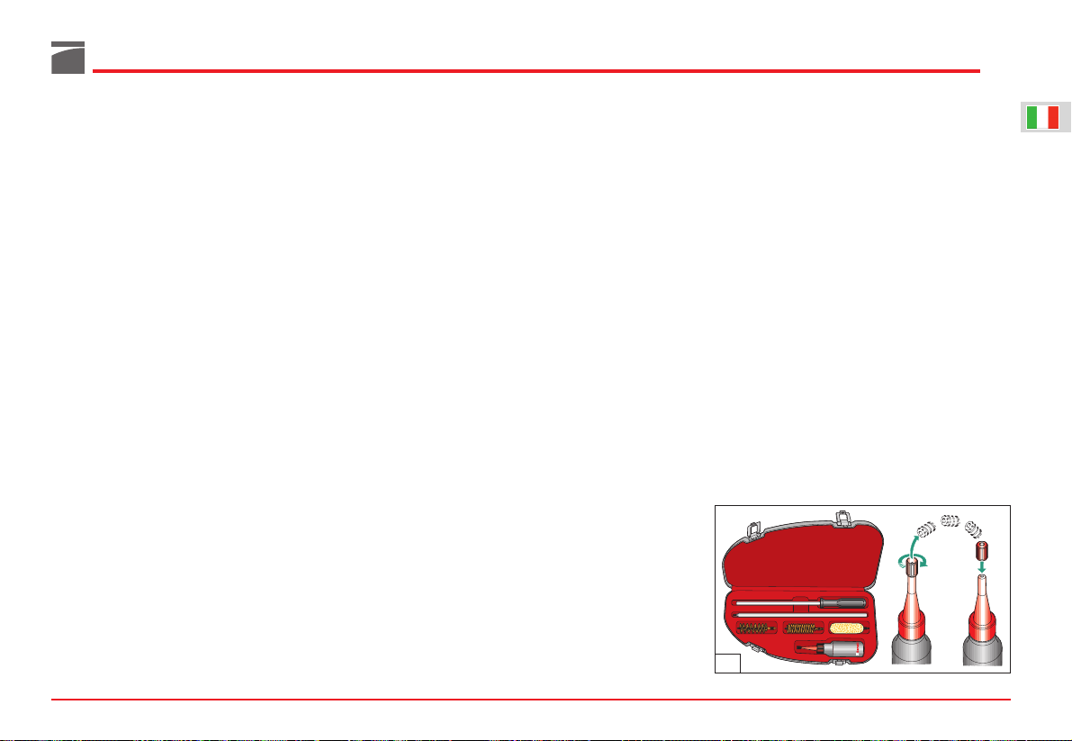
Per cambiare o pulire lo strozzatore interno agire
nel seguente modo:
1) Svitare lo strozzatore interno utilizzando la
speciale chiave dentata in dotazione all’arma
e sfilarlo completamente dalla sede della
canna (fig. 58).
2) Qualora la sede filettata dello strozzatore
sulla canna sia molto sporca, pulirla utilizzando la parte opposta della chiave.
3) Rimontare nella sede canna il tipo di strozzatore desiderato, avendo cura di inserirlo
all’interno della canna dalla parte non filetta-
ta (fig. 59); avvitarlo poi sul filetto della canna
stessa.
4) Completare il montaggio dello strozzatore
serrandolo con l’apposita chiave dentata (fig.
60).
57
Page 26

ATTENZIONE: lo strozzatore correttamente
montato non deve sporgere dalla volata della
canna (fig. 61).
ATTENZIONE: prima di riutilizzare l’arma assi-
curarsi di aver tolto la chiave per strozzatore
dalla volata della canna (fig. 62).
Prima di lasciare l’arma inutilizzata per un lungo
periodo, è consigliabile la pulizia dello strozzatore interno e della sua sede nella volata della
canna.
Gli strozzatori Benelli sono marcati per una
rapida identificazione (fig. 63). Le intacche sulla
parte frontale di ogni strozzatore permettono
un rapido riconoscimento della strozzatura, anche quando lo strozzatore è montato.
ATTENZIONE: prima di utilizzare cartucce a pal-
lini d’acciaio, assicurarsi che lo strozzatore montato sulla canna riporti la scritta STEEL SHOT –
OK (vedi tabella sopra).
25
58
59
60
61
62
A Intacche B Simbolo
63
I
NTACCHE
S
TROZZATURA
S
IMBOLO
P
ALLINI
D’ACCIAIO
I Full X NO
I Full - Steel Shot - OK X OK
II Improved Modified XX NO
II Improved Modified - Steel Shot - OK XX OK
III Modified XXX OK
IIII Improved Cylinder XXXX OK
IIIII Cylinder XXXXX OK
Page 27
Sostituzione del mirino
Per le sole canne con bindella in fibra di carbonio è possibile sostituire il mirino lungo (in fibra
ottica rossa), con i mirini in fibra ottica gialla o
verde in dotazione con l’arma.
26
Bindelle intercambiabili
Prima di effettuare qualunque tipo di intervento
sul fucile, accertarsi sempre che camera di scoppio e serbatoio siano completamente vuoti!
(Leggere attentamente le istruzioni di caricamento e scaricamento dell’arma).
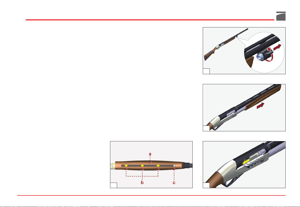
Come standard, l'arma è dotata della bindella
bassa larga 8 mm.
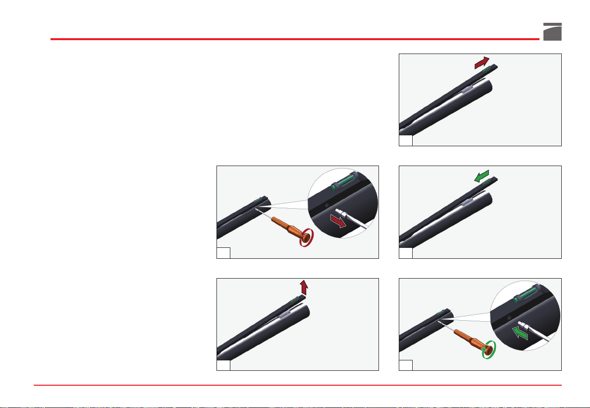
La sua sostituzione con le altre versioni è di facile esecuzione, agendo come segue:
1) Svitare e sfilare la vite di fissaggio bindella,
posizionata sull'estremità anteriore della
canna, all'altezza del mirino (fig. 64).
2) Sollevare e sfilare la bindella dagli alloggia-
menti sulla canna, tirandola in avanti (figg.
65-66).
3) Procedere al montaggio della bindella deside-
rata, avendo cura di calzare correttamente gli
alloggiamenti, facendo poi aderire la bindella
stessa alla canna per tutta la sua lunghezza (fig.
67).
4) Bloccare la bindella con la vite di fissaggio (fig.
68).
65
64
66
68
67
Page 28
il foro in modo perpendicolare all’asse del
calcio (fig. 72).
5) Procedere al montaggio del kit comfort “2” e
quindi del calciolo sul calcio (vedi fig. 57).
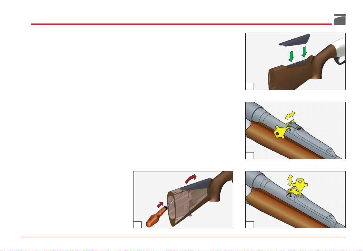
Smontaggio e sostituzione
del nasello
Per lo smontaggio e la sostituzione del nasello
agire nel modo seguente:
1) Utilizzando un cacciavite a croce, svitare le
due viti di fissaggio e staccare il calciolo “1”
(vedi fig. 57).
AVVERTENZA: per non danneggiare i calcioli,
spalmare la punta del cacciavite con vaselina o
grasso.
2) Con il medesimo cacciavite, svitare le due
viti di fissaggio ed estrarre il kit comfort “2”
dal calcio (vedi fig. 57).
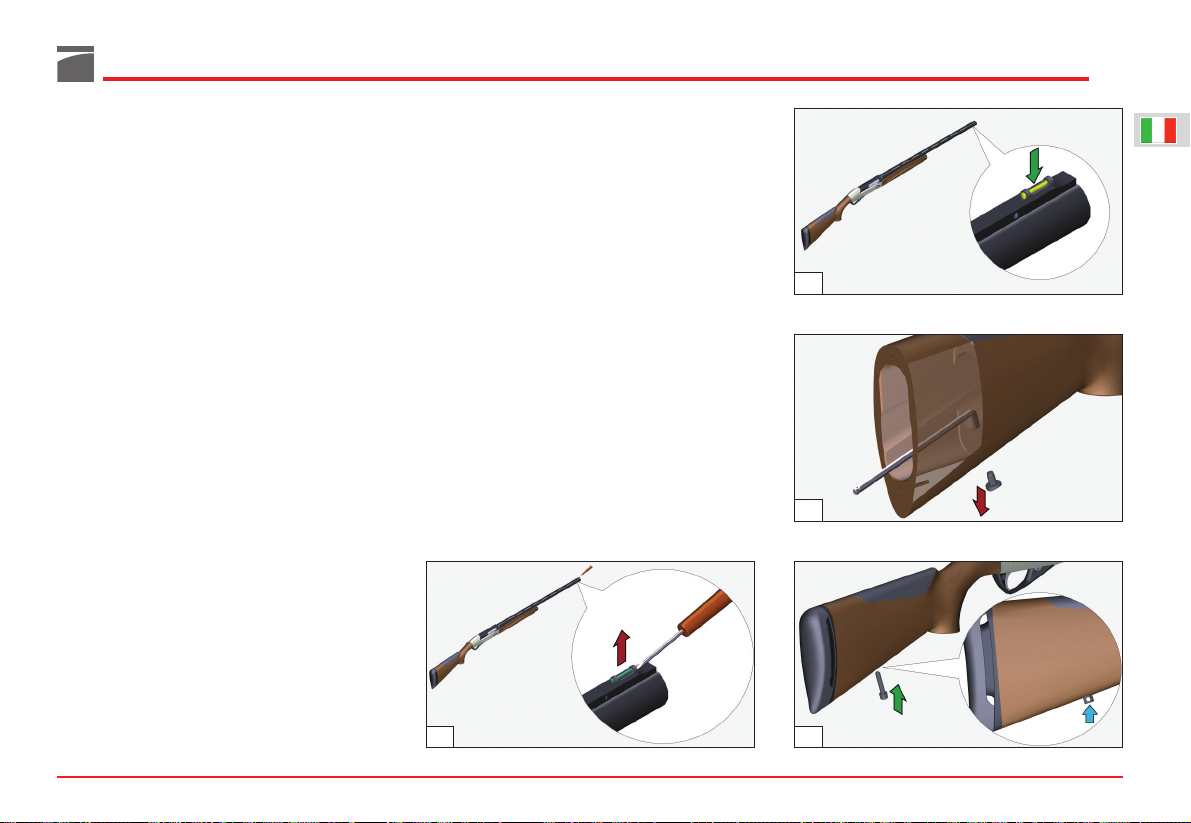
Per la sostituzione del mirino agire come segue:
1) Agendo con la punta di un cacciavite a testa
piana, sollevare il supporto mirino ed estrarlo
dalla sede sulla bindella (fig. 69).
2) Inserire il mirino sostitutivo nella sede sulla
bindella, premendolo con forza fino al bloccaggio a scatto del medesimo (fig. 70).
Montaggio del perno
per portabretella sul calcio
Per le sole armi dotate di calcio in legno, viene
fornito in dotazione un perno per fissaggio portabretella, il cui montaggio si esegue nel modo
seguente:
1) Utilizzando un cacciavite a croce, svitare le
due viti di fissaggio e staccare il calciolo “1”
(vedi fig. 57).
AVVERTENZA: per non danneggiare i calcioli,
spalmare la punta del cacciavite con vaselina o
grasso.
2) Con il medesimo cacciavite, svitare le due
viti di fissaggio ed estrarre il kit comfort “2”
dal calcio (vedi fig. 57).
3) Con l’utilizzo di una chiave a brugola, agire
dall’interno del calcio per estrarre il tappo in
gomma dal foro per perno portabretella (fig.
71).
4) Utilizzando un cacciaspine di diametro 3
mm, avvitare il perno portabretella sul foro
del calcio, portandolo a battuta ed allineando
27
70
71
69 72
Page 29
28
3) Agendo dal lato posteriore del calcio ed utilizzando l’apposito foro, premere con la
punta del cacciavite il nasello sul suo lato
inferiore, fino a sbloccarlo dal fissaggio posteriore, quindi sollevarlo per rimuoverlo dal
calcio (fig. 73).
4) Per montare il nasello sostitutivo, posizionarlo con i due perni presenti sul lato inferiore in
corrispondenza degli alloggiamenti presenti
sulla guida del calcio, quindi premere a
fondo fino al bloccaggio a scatto (fig. 74).
AVVERTENZA: il nasello correttamente montato
si allinea senza discontinuità con il profilo esterno del calcio.
5) Procedere al montaggio del kit comfort “2” e
quindi del calciolo sul calcio (vedi fig. 57).
Regolazione tacca di mira
(ove prevista)
Qualora la taratura standard effettuata in fabbrica
non risponda alle esigenze di tiro individuali, è
possibile regolare la tacca di mira sia lateralmente che verticalmente.
Prima di effettuare qualunque tipo di intervento
sul fucile, accertarsi sempre che camera di scoppio e serbatoio siano completamente vuoti!
(Leggere attentamente le istruzioni di caricamento e scaricamento dell’arma).
Regolazione laterale tacca di mira
Per la regolazione laterale della tacca di mira,
agire nel seguente modo (fig. 75):
1) Con la chiave in dotazione regolare la posizione della tacca di mira nel senso desiderato
(verso destra se si intende sparare più a destra;
verso sinistra se si intende sparare più a sinistra) facendo riferimento alle rispettive intacche graduate di allineamento.
Regolazione verticale tacca di mira
Per la regolazione verticale della tacca di mira,
agire nel seguente modo (fig. 76):
1) Con la chiave in dotazione regolare la posizione della tacca di mira nel senso desiderato (verso l’alto se si intende sparare più in
alto; verso il basso se si intende sparare più in
basso) facendo riferimento alle rispettive
intacche graduate di allineamento.
73
74
75
76
Page 30

29
CERTIFICATE OF WARRANTY
To be entitled to service under the terms of the warranty,
you must compile this form in full, get it stamped by the
dealer who sold you the firearm, and return it in a sealed
envelope to the address below.
GMK LIMITED
BEAR HOUSE - CONCORDE WAY
Fareham, Hampshire, PO15 5RL
UNITED KINGDOM
TEST CERTIFICATE
BENELLI ARMI S.p.A. declares that all its
products have been tested according to legal
requirements by the Italian national gun
testing establishment, “Banco Nazionale di
Prova”, as shown by the official marks
punched on the receiver and barrel.
MODEL
RECEIVER SERIAL NUMBER
STAMP AND SIGNATURE OF DEALER
DATE OF PURCHASE
BARREL SERIAL NUMBER
No.
No.
Notification under art. 13 of Legislative Decree 196/2003
(personal information protection code)
Personal information will be used for the purpose of issuing the product
Warranty Certificate and to provide assistance and services in relation thereto, as regulated in the General Terms specified in the Certificate itself. The
information may be communicated to companies associated with Benelli
Armi S.p.A. in the form of parent, subsidiary and/or affiliated companies, both
in Italy and abroad, and companies who provide Benelli Armi S.p.A. with
specific supply services. Personal data is not diffused. The interested party
may exercise his or her rights under art. 7 of Legislative Decree 196/03 at any
time, by writing to privacy@benelli.it
. The data controller is Benelli Armi
S.p.A., via della Stazione 50, 61029 Urbino, Italy. The Data Manager is Mr.
Lorenzo Caldari, whose offices for the purpose are located at the premises of
the Data Holder. Full information on www.benelli.it
Page 31

30
CERTIFICATE OF WARRANTY
BENELLI ARMI S.p.A. guarantees all metal parts of
its shotguns and rifles to be free of defects in
manufacturing and materials for a period of 5 years
from the date of purchase as proven by a fiscal
receipt.
During this period, the products covered by this
warranty shall be repaired free of charge by
Benelli’s Technical Assistance Centre in Urbino,
Italy, or by an Authorised Benelli Service Centre.
The purchaser remains liable for all shipping costs.
The warranty period commences on the original
date of purchase: replacement or repair of any
components will not result in an extension of the
guarantee period.
Under no circumstances shall the complete
firearm be replaced.
This warranty excludes all damage caused by
negligence, inadequate maintenance, tampering,
repair by unauthorised persons, the use of
ammunition that does not conform to international
standards, manually loaded and/or reloaded
ammunition, improper use of the firearm, failure
to comply with the safety precautions given in the
use and maintenance manual, and by events not
deriving from the normal use and functioning the
firearm.
BENELLI ARMI S.p.A. declines all responsibility for
injury to persons or animals or damage to property
caused directly or indirectly by lack of care and/or
skill in handling the firearm, or by any of the
conditions listed above.
THIS DOCUMENT MUST BE RETAINED
BY THE PURCHASER
To be entitled to service under the terms of
the warranty, you must compile this Form in
full, get it stamped by the authorised Benelli
dealer who sold you the firearm and return
it in a sealed envelope.
Failure to return this form or failure to
provide the information requested will
lead to all repairs to the product being
made only against payment.
IMPORTANT
I authorise use of my details for the purposes of commercial
information and direct offers
(Notification under art. 13 of Legislative Decree 196/2003)
Signature: ...............................................................................
MODEL
RECEIVER SERIAL
NUMBER
BARREL SERIAL
NUMBER
NAME
SURNAME
STREET
POST CODE/
ZIP CODE
CITY
COUNTRY
e-mail
STAMP AND SIGNATURE OF DEALER
No.
No.
DATE OF PURCHASE
Page 32

CERTIFICATE OF WARRANTY
To be entitled to service under the terms of the warranty,
compile this form in full, get it stamped by your authorised
Benelli dealer, and return it to your national importer in a
sealed envelope.
Details of importers can be found in the “Support” section
of the www
.benelli.it website.
TEST CERTIFICATE
BENELLI ARMI S.p.A. declares that all its
products have been tested according to legal
requirements by the Italian national gun
testing establishment, “Banco Nazionale di
Prova”, as shown by the official marks
punched on the receiver and barrel.
MODEL
RECEIVER SERIAL NUMBER
STAMP AND SIGNATURE OF DEALER
DATE OF PURCHASE
BARREL SERIAL NUMBER
No.
No.
Notification under art. 13 of Legislative Decree 196/2003
(personal information protection code)
Personal information will be used for the purpose of issuing the product
Warranty Certificate and to provide assistance and services in relation thereto, as regulated in the General Terms specified in the Certificate itself. The
information may be communicated to companies associated with Benelli
Armi S.p.A. in the form of parent, subsidiary and/or affiliated companies, both
in Italy and abroad, and companies who provide Benelli Armi S.p.A. with
specific supply services. Personal data is not diffused. The interested party
may exercise his or her rights under art. 7 of Legislative Decree 196/03 at any
time, by writing to privacy@benelli.it
. The data controller is Benelli Armi
S.p.A., via della Stazione 50, 61029 Urbino, Italy. The Data Manager is Mr.
Lorenzo Caldari, whose offices for the purpose are located at the premises of
the Data Holder. Full information on www.benelli.it
31
Page 33

CERTIFICATE OF WARRANTY
BENELLI ARMI S.p.A. guarantees all metal parts of
its shotguns and rifles to be free of defects in
manufacturing and materials for a period of 5 years
from the date of purchase as proven by a fiscal
receipt.
During this period, the products covered by this
warranty shall be repaired free of charge by
Benelli’s Technical Assistance Centre in Urbino,
Italy, or by an Authorised Benelli Service Centre.
The purchaser remains liable for all shipping costs.
The warranty period commences on the original
date of purchase: replacement or repair of any
components will not result in an extension of the
guarantee period.
Under no circumstances shall the complete
firearm be replaced.
This warranty excludes all damage caused by
negligence, inadequate maintenance, tampering,
repair by unauthorised persons, the use of
ammunition that does not conform to international
standards, manually loaded and/or reloaded
ammunition, improper use of the firearm, failure
to comply with the safety precautions given in the
use and maintenance manual, and by events not
deriving from the normal use and functioning the
firearm.
BENELLI ARMI S.p.A. declines all responsibility for
injury to persons or animals or damage to property
caused directly or indirectly by lack of care and/or
skill in handling the firearm, or by any of the
conditions listed above.
THIS DOCUMENT MUST BE RETAINED
BY THE PURCHASER
To be entitled to service under the terms of
the warranty, you must compile this Form in
full, get it stamped by the authorised Benelli
dealer who sold you the firearm and return
it in a sealed envelope.
Failure to return this form or failure to
provide the information requested will
lead to all repairs to the product being
made only against payment.
IMPORTANT
I authorise use of my details for the purposes of commercial
information and direct offers
(Notification under art. 13 of Legislative Decree 196/2003)
Signature: ...............................................................................
MODEL
RECEIVER SERIAL
NUMBER
BARREL SERIAL
NUMBER
NAME
SURNAME
STREET
POST CODE/
ZIP CODE
CITY
COUNTRY
e-mail
STAMP AND SIGNATURE OF DEALER
No.
No.
DATE OF PURCHASE
32
Page 34

33
Data subject to modification without notice.
Index
USE • MAINTENANCE ................................................................ 33
Basic safety rules ....................................................................... 34
Introduction .............................................................................. 36
Operation .................................................................................. 36
Assembly ................................................................................... 38
Gun safety catch ....................................................................... 39
Loading ..................................................................................... 40
Cartridge replacement ............................................................... 41
Unloading ................................................................................. 42
Troubleshooting ......................................................................... 43
Ammunition .............................................................................. 43
Maintenance ............................................................................. 43
Shotgun stripping ...................................................................... 44
Shotgun assembly ...................................................................... 47
A
CCESSORIES AND ADJUSTMENTS
:
Drop and cast adjustments ........................................................ 49
Internal choke ........................................................................... 50
Interchangeable ribs .................................................................. 52
Changing the front sight ............................................................ 52
Fitting the sling attachment pin to the stock .............................. 53
Removing and changing the comb ............................................ 53
Adjusting the rear sight (when fitted) ......................................... 54
Adjusting the rear sight for windage .......................................... 54
Adjusting the rear sight for elevation ......................................... 54
SPARE PARTS ............................................................................. 211
Page 35

34
BASIC SAFETY RULES
WARNING: PLEASE READ THIS MANUAL
BEFORE HANDLING YOUR FIREARM.
WARNING: FIREARMS CAN BE DANGEROUS
AND CAN POTENTIALLY CAUSE SERIOUS
INJURY, DAMAGE TO PROPERTY OR DEATH,
IF HANDLED IMPROPERLY. THE FOLLOWING
SAFETY RULES ARE AN IMPORTANT REMINDER THAT FIREARM SAFETY IS YOUR
RESPONSIBILITY.
1. NEVER POINT A FIREARM AT SOMETHING
THAT IS NOT SAFE TO SHOOT.
Never let the muzzle of a firearm
point at any part of your body or at
another person. This is especially
important when loading or unloading the firearm. When you are
shooting at a target, know what is
behind it. Some bullets can travel
over a mile. If you miss your target
or if the bullet penetrates the target,
it is your responsibility to ensure that
the shot does not cause unintended injury or
damage.
2. ALWAYS TREAT A FIREARM AS IF IT WERE
LOADED.
Never assume that a firearm is unloaded. The
only certain way to ensure that a firearm has the
chamber empty is to open the chamber and
visually and physically examine the inside to see
if a round is present.
Removing or unloading the magazine will not
guarantee that a firearm is unloaded or cannot
fire. Shotguns and rifles can be checked by
removing all rounds and by then opening and
inspecting the chamber so that a visual inspection of the chamber for any remaining rounds
can be made.
3. STORE YOUR FIREARM SO THAT CHILDREN
CANNOT GAIN ACCESS TO IT.
It is your responsibility to ensure that children
under the age of 18 or other unauthorized persons do not gain access to your firearm. To reduce the risk of accidents involving
children, unload your firearm, lock
it and store the ammunition in a
separate locked location. Please
note that devices intended to prevent accidents - for example, cable
locks, chamber plugs, etc, - may not
prevent use or misuse of your
firearm by a determined person.
Firearm storage in a steel gun safe may be more
appropriate to reduce the likelihood of intentional misuse of a firearm by an unauthorized child
or person.
4. NEVER SHOOT AT WATER OR AT A HARD
SURFACE.
Shooting at the surface of water or at
a rock or other hard surface increases the chance of ricochets or
fragmentation of the bullet or shot,
which can result in the projectile
striking an unintended or peripheral target.
5. KNOW THE SAFETY FEATURES OF THE
FIREARM YOU ARE USING, BUT REMEMBER:
SAFETY DEVICES ARE NOT A SUBSTITUTE
FOR SAFE HANDLING PROCEDURES.
Never rely solely on a safety device to prevent an
accident. It is imperative that you know and use
the safety features of the particular firearm you
are handling, but accidents can best be prevented by following the safe handling procedures
described in these safety rules and elsewhere in
the product manual.
To further familiarize yourself with the proper use
of this or other firearms, take a Firearms Safety
Course taught by an expert in firearms use and
safety procedures.
6. PROPERLY MAINTAIN YOUR FIREARM.
Store and carry your firearm so that
dirt or lint does not accumulate in
the working parts. Clean and oil
your firearm, following the instructions provided in this manual, after
each use to prevent corrosion, damage to the
barrel or accumulation of impurities which can
prevent use of the gun in an emergency. Before
loading your firearm, always check the barrel
internal part and the chamber to ensure that they
are clean and free from obstructions.
Firing with an obstruction in the barrel or chamber can rupture the barrel and injure you or
others nearby. In the event you hear an unusual
noise when shooting, stop firing immediately,
engage the manual safety and unload the
firearm.
r
e
g
e
o
t
S
Page 36

Make sure the chamber and barrel are free from
any obstruction, like a bullet blocked inside the
barrel due to defective or improper ammunition.
7. USE PROPER AMMUNITION.
Only use factory-loaded, new ammunition
manufactured to industry specifications: CIP
(Europe and elsewhere), SAAMI® (U.S.A.). Be
certain that each round you use is in the proper
caliber or gauge and type for the particular
firearm.
The caliber or gauge of the firearm is clearly
marked on the barrels of shotguns and on the
slide or barrel of pistols.
The use of reloaded or remanufactured ammunition can increase the likelihood of excessive
cartridge pressures, case-head ruptures or other
defects in the ammunition that can cause damage to your firearm and injury to yourself or
others nearby.
8. ALWAYS WEAR PROTECTIVE GLASSES AND
EARPLUGS WHEN SHOOTING.
The chance that gas, gunpowder or
metal fragments will blow back and
injure a shooter who is firing a gun
is rare, but the injury that can be
sustained in such circumstances can
be severe, including the possible loss of eyesight.
A shooter must always wear impact resistant
shooting glasses when firing any firearm.
Earplugs or other high-quality hearing protectors
help reduce the chance of hearing damage from
shooting.
9. NEVER CLIMB A TREE, FENCE OR OBSTRUCTION WITH A LOADED FIREARM.
Open and empty the chamber of
your firearm and engage the manual
safety catch before climbing or
descending a tree or before climbing
a fence or jumping over a ditch or
other obstruction. Never pull or push a loaded
firearm toward yourself or another person.
Always unload the firearm, visually and physically check to see that the magazine, loading
mechanism and chamber are unloaded and that
the bolt is open before handing the firearm to
another person.
Never take a firearm from another person unless
it is unloaded, visually and physically checked to
confirm it is unloaded, and the action is open.
10. AVOID ALCOHOLIC BEVERAGES OR JUDG-
MENT/ REFLEX IMPAIRING MEDICATION
WHEN SHOOTING.
Do not drink and shoot. If you take
medication that can impair motor
reactions or judgment, do not handle
a firearm while you are under the
influence of the medication.
11. NEVER TRANSPORT A LOADED FIREARM.
Unload a firearm before putting it in
a vehicle (chamber empty, magazine
empty). Hunters and target shooters
should load their firearm only at their
destination, and only when they are
ready to shoot. If you carry a firearm for self-pro-
tection, leaving the chamber unloaded can reduce the chance of an unintentional discharge.
12. LEAD WARNING.
Discharging firearms in poorly ventilated areas,
cleaning firearms, or handling ammunition may
result in exposure to lead and other substances
known to cause birth defects, reproductive harm,
and other serious physical injury. Have adequate
ventilation at all times. Wash hands thoroughly
after exposure.
WARNING: it is YOUR responsibility to know
and abide by Federal, State and Local laws
governing the sale, transportation and use of
firearms in your area.
WARNING: this firearm has the capability of
taking your life or the life of someone else!
Always be extremely careful with your firearm.
An accident is almost always the result of not following basic firearm safety rules.
Especially for U.S. consumers:
For information about Firearm Safety Courses in
your area, please visit the National Rifle
Association’s web site at www.nra.org.
35
Page 37

36
Introduction
Benelli Armi is proud to present the new
Raffaello. Its exclusive technology and significantly restyled looks have been especially chosen
to allow Benelli Armi’s most popular family of
shotguns to establish itself as a true hunting
classic with a modern, high-tech heart.
Thanks to the constant commitment of Benelli
Armi’s Research and Development Centre, the
new Raffaello incorporates Benelli’s superb and
innovative Progressive Comfort system in addition to all the usual benefits of Benelli shotguns.
The Progressive Comfort system is the only
recoil damping system for wooden stocks that
adapts its action to match the power of the cartridges used and damps recoil progressively. The
Progressive Comfort stock combines with the
comb to form the Benelli Full Comfort system.
The new Raffaello sets the highest standards and
represents a truly precious addition to Benelli’s
vast range of firearms.
Operation
The new “Benelli” semi-automatic shotguns operate on the same basic principle of inertial oper-
ation, with fixed barrel, utilizing the kinetic energy
of gun recoil, today still the most important, ingenious feature of our guns.
As you know, this system requires no outlet for
gas or barrel recoil, but operates by means of a
spring freely interposed between bolt head and
bolt.
During firing, due to the recoil of the gun, the
(inert) bolt moves about 4 mm forward, in relation to the power of the cartridge, compressing
the spring. When this is fully compressed, it
extends, making the whole bolt assembly move
back, thus permitting the cartridge case extraction and the gun reloading according to the conventional system.
Spring pressure is designed to delay the opening
of the action and regulate the different pressures
produced by cartridges of varying power, with no
need for braking.
We have added to this system a simple shape
and robust rotating bolt head which with only 2
locking teeth, closes the breech axially and perfectly, withstanding any pressure of the cartridge.
The new line of shotguns features a loading
system designed to:
- make it possible to shift cartridge manually
from the magazine tube to the barrel for quick
and easy ammunition changes;
- ensure even faster and safer automatic re-loading;
- check whether the hammer is cocked and
ready to shoot.
The new loading system features a special cartridge drop lever, the outer portion of which protrudes below the receiver and is thus easily reached by the trigger finger.
Upon shooting, the hammer spring forces the
cartridge drop lever upwards to disengage it from
the carrier latch which, pulled by the carrier
latch spring, rotates clockwise to allow a cartridge
to exit from the magazine.
As the cartridge falls into position on the carrier,
it presses against the carrier latch, which rotates
in the opposite direction to prevent a second cartridge from exiting.
When the bolt is operated the carrier rises automatically to position the cartridge for introduction in the chamber.
In the meantime, the hammer spring, which was
compressed during cocking, has freed the cartridge drop lever to return to its rest position.
In this way, the carrier latch is obliged to hold the
remaining cartridges in the magazine until the
next shot is fired.
The end of the cartridge drop lever which protrudes from the receiver is marked with a red
point. When the red point is visible, the hammer
is cocked and the gun is ready to fire; otherwise
the hammer is not cocked.
Like all Benelli automatic shotguns, the fully
automatic operation of the new shotguns
depends on its recoil.
This eliminates the drawbacks of the systems
with barrel recoil (barrel vibration during firing,
KEY TO ARROW COLOURS
colour description
red stripping sequence
green assembly sequence
blue location
yellow action
Page 38

need to brake the system and regulate it when
firing powerful ammunition etc.) and those of the
gas operated type (need to clean gas outlets, loss
of power due to acceleration of the shot charge
and adverse effect on the longitudinal conformation of the wad and possible malfunctions
under adverse climatic conditions), producing a
modern, highly reliable gun.
The new semi-automatic shotguns work with a
vast range of shells. The inertia system requires,
in any case, shells that generate enough kinetic
energy (recoil) to fully cycle the action.
The vast experience of our ballistic laboratory
and extensive field testing have allowed us to
establish exactly the right parameters needed to
ensure the correct functioning of your shotgun.
In particular, we have determined 200 kgm as
the minimum kinetic energy required from a 12
gauge cartridge (measured at 1 m from the
muzzle of a manometric barrel).
WARNING: at the minimum kinetic energy stat-
ed above, correct functioning is only guaranteed
for a shotgun with a MAXIMUM total weight of
3.150 kg.
37
Page 39

38
Assembly
(from packaged gun)
Components of the package (fig. 1):
a) stock-receiver-bolt-fore-end unit
b) barrel-breech unit
WARNING: please remember to remove the plas-
tic barrel sheath before using the firearm (fig. 2).
Assembly procedure
1) Unscrew the fore-end cap (fig. 3).
2) Remove the fore-end and remove the packag-
ing plate (fig. 4).
3) Hold the stock-receiver-bolt assembly in one
hand. Place the other hand on the cocking
lever and open the bolt until it locks (fig. 5).
WARNING: should the bolt fail to engage, move
the cartridge drop lever as arrowed and repeat
the operation (fig. 6).
During this operation the bolt group should be
completely assembled and placed in the re-
ceiver, in open position (backward).
4) Hold the bolt cover steady with respect to
the receiver with one hand. Grip the barrel-
breech unit with the other hand.
3
2
1
6
4
5
Page 40

5) Slide the breech extension into the receiver
making sure that the barrel ring slides on the
magazine tube (fig. 7).
6) Push the barrel-breech assembly all the way
in (fig. 8) until it clicks into place and is firmly
seated.
NOTE: make sure that the breech extension does
not collide against the bolt locking head but
rather that it fits between the cover and the locking head.
7) Slide the fore-end over the magazine tube
(fig. 9).
8) Screw the fore-end cap on to the end of the
magazine tube and tighten it sufficiently to
hold the barrel and fore-end securely against
the receiver (fig. 10).
NOTE: always make sure that the cap spring is
inserted in the cap itself (fig. 10) before locking
the barrel and fore-end to the receiver: a missing
spring will not allow proper locking of the barrel,
causing serious damage to the shotgun.
9) Press the carrier button to close the bolt (fig.
11) .
Gun safety catch
Press the safety button on the trigger guard until
its red ring, indicating firing position, is no lon-
ger visible (fig. 12).
39
7
8
9
10
12
11
Page 41

40
Loading
Before starting any operation on your shotgun,
make sure that the chamber and the magazine
are unloaded!
(Carefully read the instructions on gun loading
and unloading).
The feed magazine holds 1, 2, 3 or 4 cartridges
(according to the model and to local regulations).
Total firing capacity is 2, 3, 4 or 5 rounds, including the one in the chamber.
Loading procedure
NOTE: make sure that the shotgun safety catch
(see “Gun safety catch”) is engaged and the
hammer cocked (so that the carrier latch can
retain the cartridges as they are inserted in the
magazine).
WARNING: for safety reasons, check if by open-
ing the bolt the shotgun is unloaded. Then close
the bolt again.
1) Make sure that the red dot on the cartridge
drop lever (indicating that the hammer is
cocked) is clearly visible (fig. 13). If it is not,
press the carrier button (a), open the bolt (b)
then close the bolt again (c) (fig. 14).
2) With the bolt closed and the hammer cocked,
reverse the gun pointing the barrel down-
wards.
3) Insert a cartridge into the magazine (fig. 15):
push it until it is retained by the carrier latch
which engages automatically (fig. 16).
Repeat the operation until the magazine is
fully loaded.
NOTE: the gun must be loaded with the hammer
cocked so that the carrier latch can retain the
cartridges as they are inserted in the magazine.
Now the gun cannot be fired unless a cartridge
is placed in the barrel, as to one of the following
procedures:
13
15
16
14
Page 42

Direct procedure (figs. 17-18):
1) Open the bolt and at the same time insert a
cartridge into the barrel through the case
ejection port.
2) Release the cocking lever: the bolt will push
the cartridge on the carrier into the chamber
and stop in the closed position.
Indirect procedure (fig. 19):
1) Open the bolt (a) and hold it open. Press the
cartridge drop lever (b) to allow the first car-
tridge to drop on to the carrier.
2) Release the bolt (c). The bolt will slide for-
ward, chambering the cartridge and locking
in closed position.
WARNING: the “indirect” loading method re-
duces the number of rounds in the magazine by
one. An additional cartridge can, however, be
inserted as described above to fill the magazine
completely.
NOTE: during this operation, always point the
gun in a safe direction, even though the safety
catch is engaged (see “Gun safety catch”).
Now the gun is loaded: when the safety catch is
moved to firing position (red ring visible), the
gun is ready for use.
WARNING: when your shotgun is new and be-
fore beginning to use it normally, a breaking-in
period may be required before your new shotgun
works perfectly with light target loads.
If you experience any initial functioning problems, we recommended firing three or four
boxes of standard hunting loads to allow for this
break-in period.
Cartridge replacement
(This operation must be carried out with the gun
safety catch engaged - see “Gun safety catch”
and barrel pointed in a safe direction)
To replace a cartridge in the chamber, two procedures can be followed:
- by manual replacement of a new cartridge;
- by using the cartridge drop lever.
Manual replacement (when the cartridge is not
coming from the magazine)
1) Rest the stock on your hip and pull the cock-
ing lever to open the bolt: the cartridge in the
chamber is extracted and ejected from the
gun (fig. 20).
41
17
18
19
20
Page 43

42
2) Insert a new cartridge even partially in the
barrel through the special ejection window
(fig. 21) and release the cocking lever to close
the bolt again.
Using the cartridge drop lever (when the cartridge is coming from the magazine)
1) Rest the stock on your hip and pull the cocking lever to open the bolt: the cartridge in the
chamber is extracted and ejected from the
gun (fig. 20).
2) Press the cartridge drop lever (fig. 22) and release the cocking lever to close the bolt
again. In this way, the cartridge will pass
quickly from the magazine to the chamber.
Unloading
(This operation must be carried out with the gun
safety catch engaged - see “Gun safety catch”
and the barrel pointed in safe direction)
To unload the shotgun, proceed as follows:
1) Open the bolt: the cartridge in the chamber
will be extracted and ejected (fig. 23).
2) Close the bolt: gently releasing the cocking
lever (fig. 24).
3) Reverse the gun and - thrusting the carrier
towards inside - press the carrier latch frontal
part with your index finger (fig. 25); the first
cartridge will come out. Repeat this procedure for each cartridge you want to remove from
the magazine.
WARNING: the shotgun can also be unloaded
by repeatedly operating the cartridge drop lever
as instructed in the "Cartridge replacement" sec-
tion.
23
25
2421
22
Page 44

Troubleshooting
Before starting any operation on your shotgun,
make sure that the chamber and the magazine
are unloaded!
(Carefully read the instructions on gun loading
and unloading).
The gun fails to fire
1) Check the safety catch: if it is engaged, push
the button to the fire position.
2) Check that there is a cartridge in the barrel.
If necessary, insert a cartridge following the
loading instructions (page 40).
3) Check the firing mechanism. If necessary,
clean and lubricate it.
Fore-end cap
Check that the fore-end cap is fitted with spring
and, especially after the first rounds, check that it
is tightened firmly, to keep the barrel firmly
against to the receiver.
Ammunition
Benelli shotguns use the kinetic energy generated by the recoil to work the action.
Use always ammunition that is powerful enough
to fully cycle the action.
WARNING: when your shotgun is new and be-
fore beginning to use it normally, a breaking-in
period may be required before your new gun
works perfectly with light target loads. If you
experience any initial functioning problems, we
recommended firing three or four boxes of stan-
dard hunting cartridges.
Choice of ammunition
Correct functioning of the shotgun is only guaranteed with cartridges of a maximum length of 58 mm
(2” 3/4 - 70 mm chamber) or 66 mm (3” - 76 mm
chamber). The shotgun accepts cartridges with
rolled turnover or crimped closures, and with lead
or steel shot.
Benelli recommends use of shot loaded ammunitions for ribbed barrels and balls for slug
barrels.
This is not mandatory but will ensure top-notch
performance.
CAUTION: never use cartridges with a case lon-
ger than the chamber.
Non-compliance to this rule would have serious
consequences for both the shotgun and the
shooter.
No adjustment to the shotgun is necessary to fire
any of the ammunition listed above.
Always use ammunition that is powerful enough
to fully cycle the action.
All Benelli shotguns are subjected to a 1370 bar
burst test at the Italian National Proof House in
Gardone Valtrompia (Brescia).
Maintenance
Before starting any operation on your shotgun,
make sure that the chamber and the magazine
are unloaded! (Carefully read the instructions on
gun loading and unloading).
Thanks to its extreme simplicity and excellent
materials, the Benelli Automatic Shotgun requires
no special maintenance.
The following few controls are recommended:
1) normal cleaning of the barrel after use;
2) the firing mechanism, consisting of hammer,
trigger, etc., may become clogged with any
powder residuals (or foreign matters). Remove
them by periodical cleaning or lubrication;
3) the bolt assembly may also become clogged
with the same residuals over mentioned and
therefore must be periodically dismantled,
cleaned and lubricated;
4) to keep the gun in good order, oiling of the
parts subject to atmospheric corrosion is
recommended.
43
26
Page 45

44
NB: all barrels are internally chromium plated.
NOTE: when cleaning a barrel with an internal
choke fitted, leave the choke in place to prevent
powder residues from fouling the threads inside
the muzzle.
For a proper maintenance of your firearm, use
Benelli cleaning kit (not supplied).
Benelli oil is recommended for lubricating and
protecting mechanical parts (receiver, bolt and
barrel) (fig. 26).
Benelli recommends use of specific products for
cleaning other parts (wooden, technopolymer
and camouflage or painted stock and fore-end).
Avoid that parts get in contact with oils contain-
ing solvents or chemical substances in general,
which could alter or damage their surfaces.
Shotgun stripping
(for cleaning and maintenance)
Before starting any operation on your shotgun,
make sure that the chamber, carrier and the
magazine are unloaded!
(Carefully read the instructions on gun loading
and unloading).
WARNING
(for models where ShellView is available)
Even though the ShellView allows you to see if
your gun magazine is empty, please be advised
that while the magazine may seem to be empty
to the eye, this does not guarantee that the gun
is completely unloaded (fig. 27). Always physically and visually check the magazine and chamber to verify that the firearm is not loaded.
Please always follow all the Safety Rules given in
this manual.
28
29
30
a Benelli ShellView in the fore-end
b cartridges still in the magazine
c cartridge missing
27
Page 46

Stripping procedure
1) Unscrew the fore-end cap and remove the
fore-end making it slide forward along the
magazine tube (figs. 28-29).
2) Take the gun in one hand and with the other
open the bolt (fig. 30); should the bolt fail to
engage, move the cartridge drop lever as
arrowed and repeat the operation (fig. 31).
3) While resting the shotgun on your hip, keep
it with one hand so that the cover remains
fixed to the receiver and with the other hand
pull the barrel-breech assembly out of the
receiver (fig. 32).
4) Pull the cocking lever off with a firm tug (fig.
33).
5) Separate the cover from the receiver, pulling
it forward from the bolt assembly (fig. 34).
6) While holding the bolt assembly with one
hand (fig. 35) so as to counter-balance the
thrust of the recoil spring, push the carrier
button and ease the bolt forward until the
recoil spring no longer pushes it forward.
7) Pull the bolt assembly out of the receiver,
sliding it along its guides (fig. 36).
45
31 34
33
32
36
35
Page 47

46
8) Remove the firing pin retaining pin from the
bolt assembly, while holding the firing pin
and firing pin spring in place (fig. 37).
9) Remove the firing pin and firing pin spring
from the bolt (fig. 38).
10) Remove the locking head rotating pin from
its seat (fig. 39).
11) Remove the bolt locking head from the bolt
(fig. 40).
12) Remove the recoil spring from its seat in the
bolt (fig. 41).
13) Extract the trigger guard pin from the stock-
receiver unit, thrusting it from right or left
with the point of the same firing pin or
punch (fig. 42).
14) Press the carrier button and extract the trig-
ger guard assembly towards the front (fig.
43).
The shotgun is now completely stripped. All the
parts that require routine maintenance and cleaning are disassembled.
38
40
39
41
43
42
37
Page 48

Shotgun assembly
For correct assembly after cleaning and maintenance operations, proceed as follows:
1) Cock the hammer (fig. 44). Grip the stock-
receiver assembly, press the carrier button
and insert the complete trigger guard
assembly - with the hammer cocked - into the
receiver. Make sure that the front of the trigger
guard makes firm contact with the stop (fig.
45).
2) Push the trigger guard pin into the receiver
from the right or left, until it is completely
inside (fig. 46).
3) Slide the bolt recoil spring into its appropriate
position (fig. 47).
NOTE: always make sure that the bolt recoil
spring is positioned between the locking head
and the bolt itself, in order to avoid a shot being
fired during the closing phase.
4) Slide the locking head into the bolt, making
sure that the hole on its stem coincides with
the slot on the bolt (fig. 48).
WARNING: the slanted surfaces on the locking
head’s stem should not be visible once the bolt
locking head is mounted.
5) Insert the locking head pin in its hole on the
locking head’s stem, through the slot on the
bolt (fig. 49).
NOTE: the reference line on top of the pin must
be visible and aligned with the bolt assembly
longitudinal axis (fig. 49).
47
44
46
45 48
49
47
Page 49

48
6) Insert the firing pin and the firing pin spring
inside the bolt hole (fig. 50).
NOTE: always make sure that the firing pin
spring has been mounted.
7) Insert the firing pin retaining pin in its seat,
so as to block the firing pin (fig. 51).
8) Hold the stock receiver assembly almost
horizontally and insert the bolt assembly in
its guide on the receiver (fig. 52).
WARNING: make sure that the bolt link slides
over the trigger guard assembly, positioning on
the recoil spring guide pin inside the receiver,
once the mounting has been completed (fig. 52).
9) Open the bolt acting on the locking head
frontal part (fig. 53). If the bolt doesn’t
remain in the opened position, push the cartridge drop lever in the direction shown by
the arrow and repeat the procedure.
10) Place the cover on the receiver next to the
bolt (fig. 54).
11) While keeping the cover adhering to the re-
ceiver, move it back sliding it over the bolt
until it is fully rested on the receiver back.
12) Push the cocking lever into its seat hole on
the bolt until it fits perfectly (fig. 55).
13) Finish reassembling the shotgun by repeating
all the steps for initial assembly described on
page 39 (figs. 7-8-9-10-11).
50
51
53
54
5552
Page 50

49
ACCESSORIES AND ADJUSTMENTS
Drop and cast adjustment
Before beginning any operation on your shotgun, always make sure that chamber and
magazine have been completely emptied!
(Carefully read loading and unloading instructions).
The shotgun is supplied with a “drop change kit”
(fig. 56) which enables you to adjust the original
drop the shotgun is supplied with.
The kit includes steel stock locking plates and
plastic drop change shims in addition to a pin for
fitting a sling attachment (for wooden stocks).
The kit enables you to obtain five different drop
patterns (as specified in the table) and two different
deflections (right hand or left hand). Each unit is
marked with the corresponding drop and cast
letter.
Determine if your stock drop fits you perfectly, or
whether it is either too high or too low for you.
If the stock is too low for you (meaning that the
drop is too great), select the adjustment set in
reverse alphabetic order (e.g. if the shim fitted in
the factory is marked “C”, switch to that marked
“B” and to the corresponding stock locking
plate).
Proceed as follows to change shims (fig. 57).
1) Unscrew the two fixing screws and remove
the butt plate “1” (using a cross-head screwdriver).
WARNING: to avoid damaging the butt plates,
apply a light coat of vaseline or grease to the
shaft of the screwdriver.
2) Unscrew the two fixing screws using a
Phillips screwdriver and remove the comfort
kit “2” from the stock.
Matching instructions: the drop change shims and
stock locking plates in the kit are identified by letters.
To ensure a correct drop, always use plates and shims
with the same letter, e.g.: C - CDX – for a 60-RH drop
or C - CSX – for a 60-LH drop.
DX = Right hand
SX = Left hand
3) Unscrew the stock retaining nut “3” (using a
13 mm hexagon wrench).
4) Remove the nut “3”, from the recoil spring
tube and remove the rubber washer “4”,
stock locking plate “5”, stock “6”, cast shim
“7” and drop shim “8”.
WARNING: if the stock spacer “9” doesn't
remain inside the stock, reassemble it with the
seat of plate “5” facing the butt plate.
5) Assemble the drop shim “8” that you have
selected onto the recoil spring tube with the
stamped letter facing the stock.
6) Reassemble the selected cast shim “7” with
the stamped letter (DX or SX) facing toward
the stock.
7) Point the barrel towards the floor and fit the
stock. Engage the stock locking plate “5” in
the stock with the side punched with the
chosen letter facing the butt plate.
56
DROP CHANGE SCHEDULE
Cast Stock Drop
shim locking plate shim
(plastic) (steel) (plastic)
Reference Reference Reference
letter letter letter
DX Z DX
Z
45 ± 1 DX
SX Z SX 45 ± 1 SX
DX A DX
A
50 ± 1 DX
SX A SX 50 ± 1 SX
DX B DX
B
55 ± 1 DX
SX B SX 55 ± 1 SX
DX C DX
C
60 ± 1 DX
SX C SX 60 ± 1 SX
DX D DX
D
65 ± 1 DX
SX D SX 65 ± 1 SX
Drop value
at heel (mm)
Page 51

50
8) Fit the rubber washer “4” then screw the
nut “3” on to the end of the recoil spring
tube. Tighten the nut securely.
9) Fit the comfort kit “2” inside the stock and
secure it with its two screws using a Phillips
screwdriver.
10) Fit the butt plate “1” and secure it with its
two screws using a Phillips screwdriver.
Having altered the stock drop of the shotgun,
you have also obviously altered the firing position as well: it is therefore necessary that you
first practise by executing some shots in order to
make sure that the firing position is suitable to
your size and shooting style.
WARNING: on completion of the drop change,
check that the stock is securely fixed to the receiver. Check again after firing the first few rounds
and, if necessary, re-tighten the nut with a suitable wrench to fix the stock securely in place.
Internal choke
Before starting any operation on your shotgun,
make sure that the chamber and the magazine
are unloaded!
(Carefully read the instructions on gun loading
and unloading).
The barrels with internal chokes are equipped
with various types of chokes.
WARNING: before using the shotgun, make
sure that the barrel has a choke correctly
installed.
NOTE: if correctly installed, internal chokes
must not protrude from the barrel’s muzzle.
Only use Benelli chokes of a length suitable for
the choke seat of the barrel.
To change or clean the internal choke, proceed
as follows:
1) Unscrew the internal choke using the special
choke wrench supplied with the shotgun and
extract it completely from the barrel seat (fig.
58).
2) If the choke threads become badly fouled,
clean them with the serrated side of the choke
wrench.
3) Reassemble the kind of choke required on the
barrel seat, taking care to insert the non-
threaded part inside the barrel; then screw
the choke on the barrel thread (fig. 59).
4) Complete installation of the choke using the
toothed wrench provided (fig. 60).
57
Page 52

NOTE: when choke is correctly mounted, it must
not protrude from the barrel’s muzzle (fig. 61).
NOTE: before re-using the shotgun, make sure
that the choke wrench has been removed from
the barrel’s muzzle (fig. 62).
Before the shotgun is put away, cleaning the
internal choke and relative barrel thread is
recommended.
Benelli chokes are marked for an easy identification (fig. 63). Notches on the frontal part of
each choke allow a quick recognition, even
when the choke is mounted on the shotgun.
NOTE: before using steel shot cartridges, make
sure that the choke fitted in the barrel is marked
“STEEL SHOT – OK” (see table above).
51
58
59
60
61
62
N
OTCHES
C
HOKE
S
YMBOL
S
TEEL
S
HOT
I Full X NO
I Full - Steel Shot - OK X OK
II Improved Modified XX NO
II Improved Modified - Steel Shot - OK XX OK
III Modified XXX OK
IIII Improved Cylinder XXXX OK
IIIII Cylinder XXXXX OK
A Notches B Symbol
63
Page 53

52
Interchangeable ribs
Before starting any operation on your shotgun,
make sure that the chamber and the magazine
are unloaded!
(Carefully read the instructions on gun loading
and unloading).
The shotgun is fitted as standard with a low, 8
mm wide rib.
The rib can be easily replaced, following the
instructions below:
1) Unscrew and remove the rib fixing screw
from the front end of the barrel, near the front
sight (fig. 64).
2) Lift and extract the rib from its seat on the bar-
rel pulling it forward (figs. 65-66).
3) Place the required rib, taking care to properly
insert the housings, then set the rib along the
barrel for the whole length (fig. 67).
4) Fix the rib with the fixing screw (fig. 68).
Changing the front sight
On shotguns with a carbon fibre rib, the red fibre
optic front sight can be changed for the yellow or
green fibre optic sight supplied.
65
64
66
68
67
Page 54

pendicular to the line of the stock (fig. 72).
5) Fit the comfort kit “2” and then the butt plate
to the stock (see fig. 57).
Removing and changing
the comb
Proceed as follows to remove and change the
comb.
1) Unscrew the two fixing screws using a
Phillips screwdriver and remove the butt
plate “1” (see fig. 57).
WARNING: smear the tip of the screwdriver
with Vaseline or grease to avoid damaging the
stock.
2) Using the same Phillips screwdriver, unscrew
the two fixing screws and remove the com-
fort kit “2” from the stock (see fig. 57).
Proceed as follows to change the front sight.
1) Use the tip of a flat blade screwdriver to prize
up the sight mounting and remove it from its
seat in the rib (fig. 69).
2) Insert the chosen sight into the seat in the rib,
pressing hard until it clicks securely into
place (fig. 70).
Fitting the sling attachment
pin to the stock
Shotguns with wooden stocks come with a sling
attachment pin. Proceed as follows to fit this to
the stock.
1) Unscrew the two fixing screws using a
Phillips screwdriver and remove the butt
plate “1” (see fig. 57).
WARNING: smear the tip of the screwdriver
with Vaseline or grease to avoid damaging the
stock.
2) Using the same Phillips screwdriver, unscrew
the two fixing screws and remove the com-
fort kit “2” from the stock (see fig. 57).
3) Use an Allen key to remove the rubber plug
from the sling attachment hole inside the
stock (fig. 71).
4) Using a 3 mm diameter punch as a tommy
bar, screw the sling attachment pin into the
hole in the stock. Tighten into firm contact
with stock, until the hole in the pin lies per-
53
70
71
69
72
Page 55

54
3) Insert the tip of a screwdriver through the
hole provided in the rear of the stock. Push
the bottom of the comb upwards to release its
back edge, then lift it and remove it from the
stock (fig. 73).
4) To fit the new comb, position it so that the
two dowels on its underside line up with the
holes in the seat on the stock, then push the
comb firmly down until it clicks into place
(fig. 74).
WARNING: the edges of the comb must mate
perfectly with the profile of the stock when correctly fitted.
5) Fit the comfort kit “2” and then the butt plate
to the stock (see fig. 57).
Adjusting the rear sight
(when fitted)
If the default calibration of the rear sight proves
unsuitable, you can adjust for windage and elevation as required.
Before beginning any operation on your shotgun,
always make sure that chamber and magazine
have been completely emptied!
(Carefully read loading and unloading instructions).
Adjusting the rear sight for windage
As for lateral adjustment of the rear sight, proceed as follows (fig. 75):
1) Using the supplied key and referring to the
graduated alignment notches, adjust the rear
sight position into the required direction
(move it to the right if you want the point of
impact to move right and move it to the left if
you want the point of impact to move left).
Adjusting the rear sight for elevation
As for rear sight elevation adjustment, proceed as
follows (fig. 76):
1) Using the supplied key and referring to the
relative graduated alignment notches, adjust
the rear sight position into the required direction (move it upwards if you want to raise the
point of impact, or move downwards if you
want the point of impact to be lower).
73
74
75
76
Page 56

55
CERTIFICAT D’ESSAI
BENELLI ARMI S.p.A. déclare que tous ses
produits ont été régulièrement essayés au
Banc National de Tir, conformément à la
législation en vigueur, ainsi que l’attestent
les poinçons officiels estampillés sur la carcasse et sur le canon.
CERTIFICAT DE GARANTIE
Pour avoir droit à la garantie, envoyer sous enveloppe
fermée ce certificat dûment renseigné dans toutes ses
parties et portant le cachet du revendeur, à l’adresse cidessous.
MODÈLE
MATRICULE CARCASSE
CACHET ET SIGNATURE DU REVENDEUR
DATE D’ACHAT
MATRICULE CANON
n.
n.
Note d’information en vertu de l’art. 13 du décret législatif 196/2003
(Code en matière de protection des données personnelles)
Vos données personnelles seront traitées dans le but de délivrer le Certificat de
Garantie du produit et de fournir l’assistance et les services qui lui sont liés,
ainsi que régi par les Conditions Générales spécifiées dans ce Certificat. Ces
données pourront être communiquées aux sociétés ayant des rapports avec
Benelli Armi S.p.A. en tant que sociétés mères, sociétés contrôlées et/ou associées, aussi bien en Italie qu’à l’étranger, et aux sociétés qui fournissent à
Benelli Armi S.p.A. des services spécifiques. Ces données ne seront pas divulguées. À tout moment, la personne concernée pourra exercer ses droits en vertu
de l’art. 7 du décret législatif 196/03 en écrivant à privacy@benelli.it
. Le titulaire du traitement est Benelli Armi S.p.A., via della Stazione n. 50, 61029 Urbino,
Italie. Le responsable du traitement est M. Lorenzo Caldari, domicilié pour cette
fonction au siège du titulaire. Note d’information complète sur www.benelli.it
HUMBERT CTTS SAS
45 AVENUE PACCARD
42340 VEAUCHE
FRANCE
Page 57

56
CERTIFICAT DE GARANTIE
BENELLI ARMI S.p.A. garantit ses fusils et ses carabines
pendant une période de 5 ans à compter de la date du
premier achat (le document fiscal de premier achat faisant foi), contre tout défaut de fabrication et de matériel, relativement aux seules parties métalliques.
Le produit couvert par cette garantie sera réparé gratuitement - exception faite pour les frais d’expédition
éventuels, qui sont à la charge de l’acheteur - par le
Service Après-Vente Benelli d’Urbino ou par les
Réparateurs Agréés Benelli.
La validité de la période de garantie commence à partir de la date du premier achat: tout remplacement des
composants ou leur réparation n’implique pas l’extension de la période de garantie.
En aucun cas l’acheteur n’aura droit au remplacement de l'arme complète.
Sont exclus de cette garantie tous les dommages dus à
la négligence, au manque d’entretien, à une manipulation, à des réparations effectuées par des personnels
non autorisés, à l’utilisation de munitions non conformes aux Normes Internationales, à des munitions
chargées manuellement et/ou rechargées, à un usage
impropre de l’arme, non conforme aux instructions
indiquées dans le manuel d’Usage et d’Entretien ou,
de toute façon, tous les dommages provoqués par des
facteurs non conformes à une utilisation/un fonctionnement normal de l’arme.
BENELLI ARMI S.p.A. n’est pas responsable des dommages directs ou indirects de quelque nature que ce
soit, provoqués par des personnes, des animaux ou
des choses, dérivant d’une négligence et/ou d’une
inexpérience dans le maniement de l’arme, ainsi que
par tous les motifs indiqués au paragraphe précédent.
DOCUMENT À CONSERVER
PAR L’ACHETEUR
Pour avoir droit à la garantie, envoyer sous
enveloppe fermée ce Certificat, dûment
renseigné dans toutes ses parties et portant
le cachet du revendeur agréé Benelli.
En cas d’omission d’envoi ou d’absence
des données nécessaires à l’application des
conditions de garantie, la réparation de
l’arme sera payante.
IMPORTANT
J’autorise l’utilisation de mes données personnelles pour des
informations commerciales et des offres directes
(Note d’information en vertu de l’art. 13 du décret législatif 196/2003)
Signature: ...............................................................................
MODÈLE
MATRICULE
CARCASSE
MATRICULE
CANON
PRÉNOM
NOM
RUE
CODE POSTAL
VILLE
PAYS
e-mail
CACHET ET SIGNATURE DU REVENDEUR
n.
n.
DATE D’ACHAT
Page 58

CERTIFICAT D’ESSAI
BENELLI ARMI S.p.A. déclare que tous ses
produits ont été régulièrement essayés au
Banc National de Tir, conformément à la
législation en vigueur, ainsi que l’attestent
les poinçons officiels estampillés sur la carcasse et sur le canon.
CERTIFICAT DE GARANTIE
Pour avoir droit à la garantie, envoyez sous enveloppe
fermée ce certificat, dûment renseigné dans toutes ses
parties et portant le cachet du revendeur, à l’importateur
le plus proche de votre domicile.
Vous trouverez facilement ses coordonnées dans le site
www
.benelli.it sous la rubrique “Service après-vente”.
MODÈLE
MATRICULE CARCASSE
CACHET ET SIGNATURE DU REVENDEUR
DATE D’ACHAT
MATRICULE CANON
n.
n.
Note d’information en vertu de l’art. 13 du décret législatif 196/2003
(Code en matière de protection des données personnelles)
Vos données personnelles seront traitées dans le but de délivrer le Certificat de
Garantie du produit et de fournir l’assistance et les services qui lui sont liés,
ainsi que régi par les Conditions Générales spécifiées dans ce Certificat. Ces
données pourront être communiquées aux sociétés ayant des rapports avec
Benelli Armi S.p.A. en tant que sociétés mères, sociétés contrôlées et/ou associées, aussi bien en Italie qu’à l’étranger, et aux sociétés qui fournissent à
Benelli Armi S.p.A. des services spécifiques. Ces données ne seront pas divulguées. À tout moment, la personne concernée pourra exercer ses droits en vertu
de l’art. 7 du décret législatif 196/03 en écrivant à privacy@benelli.it
. Le titulaire du traitement est Benelli Armi S.p.A., via della Stazione n. 50, 61029 Urbino,
Italie. Le responsable du traitement est M. Lorenzo Caldari, domicilié pour cette
fonction au siège du titulaire. Note d’information complète sur www.benelli.it
57
Page 59

CERTIFICAT DE GARANTIE
BENELLI ARMI S.p.A. garantit ses fusils et ses carabines
pendant une période de 5 ans à compter de la date du
premier achat (le document fiscal de premier achat faisant foi), contre tout défaut de fabrication et de matériel, relativement aux seules parties métalliques.
Le produit couvert par cette garantie sera réparé gratuitement - exception faite pour les frais d’expédition
éventuels, qui sont à la charge de l’acheteur - par le
Service Après-Vente Benelli d’Urbino ou par les
Réparateurs Agréés Benelli.
La validité de la période de garantie commence à partir de la date du premier achat: tout remplacement des
composants ou leur réparation n’implique pas l’extension de la période de garantie.
En aucun cas l’acheteur n’aura droit au remplacement de l'arme complète.
Sont exclus de cette garantie tous les dommages dus à
la négligence, au manque d’entretien, à une manipulation, à des réparations effectuées par des personnels
non autorisés, à l’utilisation de munitions non conformes aux Normes Internationales, à des munitions
chargées manuellement et/ou rechargées, à un usage
impropre de l’arme, non conforme aux instructions
indiquées dans le manuel d’Usage et d’Entretien ou,
de toute façon, tous les dommages provoqués par des
facteurs non conformes à une utilisation/un fonctionnement normal de l’arme.
BENELLI ARMI S.p.A. n’est pas responsable des dommages directs ou indirects de quelque nature que ce
soit, provoqués par des personnes, des animaux ou
des choses, dérivant d’une négligence et/ou d’une
inexpérience dans le maniement de l’arme, ainsi que
par tous les motifs indiqués au paragraphe précédent.
DOCUMENT À CONSERVER
PAR L’ACHETEUR
Pour avoir droit à la garantie, envoyer sous
enveloppe fermée ce Certificat, dûment
renseigné dans toutes ses parties et portant
le cachet du revendeur agréé Benelli.
En cas d’omission d’envoi ou d’absence
des données nécessaires à l’application des
conditions de garantie, la réparation de
l’arme sera payante.
IMPORTANT
J’autorise l’utilisation de mes données personnelles pour des
informations commerciales et des offres directes
(Note d’information en vertu de l’art. 13 du décret législatif 196/2003)
Signature: ...............................................................................
MODÈLE
MATRICULE
CARCASSE
MATRICULE
CANON
PRÉNOM
NOM
RUE
CODE POSTAL
VILLE
PAYS
e-mail
CACHET ET SIGNATURE DU REVENDEUR
n.
n.
DATE D’ACHAT
58
Page 60

59
Données pouvant être modifiées sans obligation de préavis.
Table des matières
USAGE • ENTRETIEN ................................................................. 59
Normes de sécurité .................................................................... 60
Présentation ............................................................................... 62
Fonctionnement ......................................................................... 62
Montage .................................................................................... 64
Sûreté du fusil ............................................................................ 65
Chargement ............................................................................... 66
Remplacement cartouche .......................................................... 67
Déchargement de l’arme ........................................................... 68
Inconvénients et remèdes .......................................................... 69
Ravitaillement ........................................................................... 69
Entretien .................................................................................... 69
Démontage de l’arme ................................................................ 70
Remontage de l’arme ................................................................ 73
A
CCESSOIRES ET RÉGLAGES
:
Variation et déviation pente ......................................................... 75
Choke intérieur ......................................................................... 76
Bandes interchangeables ........................................................... 78
Remplacement du guidon ......................................................... 78
Montage de la vis de grenadière sur la crosse ........................... 79
Démontage et remplacement du busc ....................................... 79
Réglage du cran de mire (si prévu) ............................................ 80
Réglage latéral du cran de mire ................................................. 80
Réglage vertical du cran de mire ............................................... 80
PIÈCES DE RECHANGE ............................................................... 211
Page 61

60
NORMES DE SÉCURITÉ
REMARQUE: NOUS VOUS PRIONS DE LIRE AT-
TENTIVEMENT CE MANUEL AVANT DE MANIPULER VOTRE ARME.
REMARQUE: SI ELLES SONT MANIPULÉES DE
FAÇON ERRONÉE, LES ARMES À FEU PEUVENT
ÊTRE DANGEREUSES ET REPRÉSENTER UNE
SOURCE POTENTIELLE D’ACCIDENTS GRAVES,
VOIRE IRRÉPARABLES. LES NORMES DE SÉCURITÉ REPORTÉES DANS CE MANUEL REPRÉSENTENT UN RAPPEL IMPORTANT CONCERNANT LA RESPONSABILITÉ DES PROPRIÉTAIRES ET DES UTILISATEURS D’ARMES À FEU.
1. NE POINTEZ JAMAIS VOTRE ARME DANS UNE
DIRECTION QUI NE SOIT PAS TOTALEMENT
SÛRE.
Ne pointez jamais le canon de l’arme
contre vous-mêmes ou contre une
autre personne. Cette prescription revêt une importance fondamentale
lorsque vous chargez ou déchargez
votre arme. Avant de tirer contre une
cible, vérifiez avec attention ce qui se
trouve derrière cette cible. Les projectiles peuvent dépasser une distance de 1,5 km. Si vous manquez la
cible ou si le projectile la transperce, vous devez
vous assurer que le coup de feu n’a pas causé de
dommages ou de blessures à quelqu’un.
2. MANIPULEZ TOUJOURS VOTRE ARME
COMME SI ELLE ÉTAIT CHARGÉE.
Ne donnez jamais pour sûr que l’arme soit
déchargée. La seule façon pour s’assurer que la
chambre de l’arme soit vide est de l’ouvrir et de
vérifier visuellement et physiquement l’absence
de projectiles. Retirer ou décharger le magasin ne
signifie pas que l’arme est déchargée ou qu’elle ne
peut pas faire feu. Les fusils et les carabines peuvent être contrôlés en retirant tous les projectiles,
puis en ouvrant et en vérifiant la chambre d’explosion de façon à pouvoir effectuer une inspection complète et s’assurer qu’aucune balle ne soit
restée à l’intérieur.
3. CONSERVEZ VOTRE ARME DANS UN LIEU
SÛR ET NON ACCESSIBLE POUR LES ENFANTS.
Vous êtes chargés de vous assurer que les mineurs
ou autres personnes non autorisées n’aient pas
accès à l’arme. Pour réduire le risque d’accidents
envers les mineurs, déchargez l’arme, fermez-la à clé et rangez les
munitions dans un endroit séparé et
toujours fermé à clé. N’oubliez
jamais que les dispositifs utilisés pour
prévenir les accidents - comme par
ex. les cadenas pour armes, les fermetures pour chambres d’explosion,
etc. - ne suffisent pas à empêcher que
d’autres personnes puissent utiliser
l’arme à feu ou l’utiliser de façon impropre. Le
rangement de l’arme dans un étui de sécurité spécial en acier serait l’idéal pour réduire la probabilité que les mineurs ou les personnes non autorisées puissent utiliser l’arme de façon impropre.
4. NE TIREZ JAMAIS CONTRE UNE PIÈCE D’EAU
OU CONTRE DES SURFACES
DURES.
Tirer contre des pièces d’eau, contre
une roche ou d’autres surfaces dures
augmente le risque de rebondisse-
ments ou de fragmentations des projectiles, ce qui
peut vouloir dire atteindre des cibles non souhaitées ou limitrophes.
5. IL EST FONDAMENTAL QUE VOUS SOYEZ À
CONNAISSANCE DES CARACTÉRISTIQUES DE
L’ARME QUE VOUS UTILISEZ, EN TENANT
COMPTE DU FAIT QUE LES DISPOSITIFS DE
SÉCURITÉ NE REMPLACENT PAS LES PROCÉDURES DE SÉCURITÉ CONCERNANT LA MANIPULATION DE L’ARME.
Ne vous en remettez pas uniquement aux dispositifs de sécurité pour prévenir les accidents. Il est
fondamental que vous connaissiez et que vous
observiez les caractéristiques de sécurité de l’arme
que vous manipulez; dans tous les cas, les accidents peuvent être évités encore davantage en suivant les procédures de sécurité concernant la
manipulation de l’arme reportées dans les règles
de sécurité et à l’intérieur de ce manuel. Pour
familiariser davantage avec cette arme ou d’autres
armes afin de pouvoir les utiliser de façon appropriée, il est conseillé de suivre un cours sur la
sécurité des armes tenu par un professionnel du
secteur, expert dans les techniques d’utilisation et
dans les procédures de sécurité.
6. CONSERVEZ L’ARME DE FAÇON ADÉQUATE.
Conservez votre arme de façon à éviter l’accumulation de saleté ou de
poussière dans les parties mécaniques. En suivant les instructions contenues dans ce manuel, nettoyez et
lubrifiez votre arme après chaque utilisation afin
de prévenir la corrosion, les dommages au canon
ou l’accumulation d’impuretés qui peuvent empêcher le fonctionnement de l’arme en cas de néces-
r
e
g
e
to
S
Page 62

sité. Contrôlez toujours l’intérieur et la chambre
d’explosion avant de charger l’arme pour vous
assurer qu’ils soient propres et libres de toute obstruction. Tirer en présence d’obstructions dans le
canon ou dans la chambre d’explosion peut provoquer l’explosion du canon et vous blesser ou
blesser des personnes se trouvant dans le voisinage. Si vous percevez un bruit anomal durant le
coup de feu, interrompez immédiatement le tir,
enclenchez la sûreté et déchargez l’arme. Vérifiez
que la chambre et le canon soient libres de toute
obstruction, comme par exemple un projectile
bloqué à l’intérieur du canon à cause de munitions défectueuses ou inappropriées.
7. UTILISEZ DES MUNITIONS APPROPRIÉES.
Utilisez toujours des munitions de marque de
fabrique, nouvelles munitions réalisées selon les
spécifications industrielles suivantes: CIP (Europe
et autres pays), SAAMI® (U.S.A.). Contrôlez que
les projectiles soient du calibre ou du type appropriés à l’arme utilisée. Le calibre de l’arme est
indiqué clairement sur le canon du fusil ou sur le
chariot ou sur le canon du pistolet. L’emploi de
munitions rechargées ou reconstruites peut augmenter la probabilité de pression excessive sur la
cartouche, d’explosion du culot ou d’autres
défauts des munitions qui peuvent endommager
l’arme et vous blesser ou blesser les personnes qui
se trouvent près de vous.
8. PORTEZ TOUJOURS DES LUNETTES DE PROTECTION ET DES BOUCHONS
POUR LES OREILLES LORSQUE
VOUS TIREZ.
La probabilité que des gaz, des poudres ou des fragments métalliques
atteignent et blessent le tireur après le coup de feu
est rare, mais dans l’hypothèse que cela s’avère,
les blessures peuvent être graves, y compris la
possibilité de perdre la vue. Lorsque vous tirez,
vous devez toujours porter des lunettes de protection à haute résistance. Les bouchons pour les
oreilles et autres types de protection de haute qualité contribuent à réduire le risque de blessures
provoquées par le tir.
9. NE GRIMPEZ JAMAIS SUR LES ARBRES, LES CLOTURES OU LES OBSTACLES AVEC L’ARME
CHARGÉE.
Ouvrez et videz la chambre de l’arme et enclenchez la sûreté avant de
grimper ou de descendre des arbres
ou avant de sauter les clôtures ou les
fossés ou autres obstacles. Ne tirez
pas et ne poussez pas l’arme contre vous-même
ou contre une autre personne. Déchargez toujours
l’arme et contrôlez visuellement et physiquement
que le magasin, le mécanisme de recharge et la
chambre soient déchargés et que l’arme ait l'obturateur ouvert avant de la remettre dans les mains
d’un tiers. Ne prenez jamais une arme d’une autre
personne si elle n’est pas déchargée et si vous ne
l’avez pas contrôlée visuellement et physiquement
pour vous assurer qu’elle soit effectivement déchargée et, d’autre part, prenez l'arme seulement
si celui-ci est ouverte.
10. EVITEZ DE BOIRE DES BOISSONS ALCOOLI-
QUES OU D’ASSUMER DES MÉDICAMENTS
POUVANT DIMINUER VOS RÉFLEXES ET VOTRE SELF-CONTROL
PENDANT QUE VOUS TIREZ.
Ne buvez pas lorsque vous utilisez
votre arme. Si vous assumez des
médicaments pouvant diminuer vos réflexes ou
votre self-control, ne manipulez pas d’armes tant
que vous êtes sous l’effet du médicament.
11. NE TRANSPORTEZ JAMAIS UNE ARME CHARGÉE.
Déchargez toujours votre arme avant
de la poser dans un véhicule (chambre et magasin vides). Les chasseurs
et les tireurs doivent charger l’arme
lorsqu’ils sont arrivés à destination et
seulement lorsqu’ils sont sur le point de tirer. Si
vous détenez une arme pour votre défense personnelle, laissez la chambre déchargée pour réduire
la possibilité d’un coup de feu involontaire.
12. AVVERTISSEMENT SUR L’EXPOSITION AU
PLOMB.
Décharger l’arme dans des zones à faible ventilation, nettoyer des armes ou manipuler des munitions peut comporter une exposition au plomb et
à d’autres substances qui peuvent nuire à la respiration, à l’appareil reproductif et causer des dommages physiques graves. Choisissez toujours des
zones bien aérées. Lavez-vous soigneusement les
mains après l’exposition.
REMARQUE: vous êtes entièrement RESPONSA-
BLES de la connaissance et du respect des lois locales et nationales qui régissent le commerce, le
transport et l’usage des armes à feu dans votre
pays.
REMARQUE: cette arme peut tuer une personne!
Soyez toujours extrêmement attentifs lorsque vous
la manipulez. Un accident est presque toujours dû
au non respect des normes de sécurité de l’arme.
61
Page 63

62
Présentation
La société Benelli Armi a le plaisir de vous présenter le nouveau Raffaello. L’introduction de
technologies exclusives alliées à un restyling
esthétique significatif permet à l’importante
famille des Raffaello de se présenter comme des
fusils classiques, mais avec un cœur technologique moderne.
Grâce à l’engagement constant de notre Centre
d’études et de recherches, le nouveau Raffaello
possède toutes les caractéristiques des produits
Benelli, associées à une excellente innovation
du Comfort Progressive.
Le seul système anti-recul appliqué aux crosses
en bois qui, selon les cartouches employées,
s’active avec plus ou moins de force pour amortir progressivement le recul, tout en créant - avec
le busc - le système Full Comfort global.
Un nouveau défi, un fusil sans aucun doute précieux qui va enrichir la gamme déjà vaste de
produits Benelli.
Fonctionnement
Les nouveaux fusils semi-automatiques “Benelli”
se basent sur le même principe de fonctionnement inertiel, à canon fixe, utilisant l’énergie
cinétique du recul de l’arme, qui encore aujourd’hui constitue la plus importante et ingénieuse
nouveauté technique de nos armes.
Comme on le sait, ce système n’exige pas l’emprunt des gaz ni le recul du canon, mais utilise,
pour son fonctionnement, un ressort intercalé librement entre la tête de fermeture et I’obturateur.
Au moment du tir, par réaction au recul du fusil,
I’obturateur (inerte) accomplit un avancement
d’environ 4 mm, proportionnel à la puissance de
la cartouche en comprimant le ressort. A la fin de
la compression, le ressort se detend, faisant reculer tout le groupe obturateur, permettant ainsi
l’extraction de la douille et le rechargement de
l’arme qui s’effectue selon le système traditionnel.
Le ressort est chargé de façon à créer un retard à
l’ouverture, et à moduler, sans nécessité de freinage, les diverses pressions produites par les cartouches de différentes puissances.
Ce principe de fonctionnement a été combiné à
une tête de fermeture tournante, robuste et sim-
ple, qui grâce à deux seules dents de fermeture,
assure une fermeture parfaite et axiale de la
culasse, capable de supporter dans le canon les
pressions de cartouches.
La nouvelle gamme est équipée d’un système
d’alimentation spécialement étudié pour:
- permettre le passage manuel des cartouches
du magasin au canon en vue d’un changement
rapide et facile des munitions dans le canon;
- assurer une alimentation encore plus rapide et
plus sûre dans le réarmement automatique;
- vérifier rapidement si l’arme a le chien armé et
si elle est prête à tirer.
Le nouveau système d’alimentation prévoit un
levier spécial de descente de la cartouche dont la
partie extérieure dépasse le plan inférieur de la
carcasse et qui est facilement accessible au doigt
qui appuie sur la détente.
Au moment du tir, le ressort du chien fait pivoter
verticalement le levier de descente de la cartouche en le dégageant du levier d’arrêt de la cartouche. Celui-ci, du fait de son ressort de rappel,
tourne de gauche à droite permettant ainsi la sortie d’une cartouche du magasin.
Cette cartouche, en se positionnant sur l’élévateur, appuie sur le levier d’arrêt de la cartouche
en le faisant tourner dans le sens contraire et
empêchant ainsi la sortie d’une deuxième cartouche. L’élévateur, commandé par l’obturateur,
monte automatiquement et amène la cartouche
dans la position d’entrée dans la chambre.
Entre temps, le ressort du chien, déjà recomprimé
en position d’armement, a liberé le levier de
descente lui permettant de reprendre sa place.
De cette manière le levier d’arrêt de cartouche
est obligé de retenir définitivement les cartouches
encore dans le magasin jusqu’à ce qu'un nouveau coup n’aura pas été tiré.
Le levier de descente de la cartouche comporte,
bien visible sur la partie qui dépasse du plan inférieur de la carcasse, un petit point rouge. Lorsque
celui-ci est visible, le chien de l’arme est armé et
elle est prête à tirer. Dans le cas contraire, le
chien de l’arme est désarmé.
Les nouveaux fusils, utilisent, comme tous les
automatiques Benelli, I’énergie de recul de l’arme pour tous ses mouvements automatiques.
On élimine ainsi, aussi bien les inconvénients
LÉGENDE COULEURS FLÈCHES
couleur description
rouge séquence de démontage
vert séquence de montage
bleu indication
jaune actionnement
Page 64

des systèmes à canon à recul (vibrations du
canon pendant le tir, nécessité d’un frein de régulation pour les cartouches puissantes, etc.), que
les inconvénients du système procédant par
emprunt des gaz, (nécessité de nettoyage de la
prise de gaz, perte de puissance dans la vitesse
initiale de la charge de plomb et répercussion
négative sur la conformation en profondeur de la
gerbe et possibilitée des défauts lorsque les conditions atmosphériques sont défavorables). On a
ainsi une arme moderne et pleinement fiable.
Grâce à leur haut degré de perfectionnement, les
nouveaux semi-automatiques Benelli sont en
mesure de fonctionner avec une très vaste
gamme de cartouches; l’originalité du système de
fonctionnement par inertie ne demande de toute
façon à la cartouche qu’une toute petite quantité
d’énergie cinétique nécessaire pour un automatisme complet de la recharge déterminé par le
recul même de l’arme.
Des expériences approfondies de notre laboratoire balistique et des tests pratiques, nous permet-
tent de fixer les paramètres pour un fonctionnement correct de l’arme, en déterminant à 200
kgm la valeur minimum de l’énergie cinétique
développée par la cartouche cal. 12 (valeur
mesurée sur le canon manométrique à 1 m de la
bouche du canon).
AVERTISSEMENT: le fonctionnement correct de
l’arme, avec la valeur minimum de l’énergie
cinétique indiquée, est garanti pour une arme
d’un poids total MAXIMUM de 3,150 kg.
63
Page 65

64
Montage
(fusil emballé)
Pièces de l’emballage (fig. 1):
a) groupe crosse-carcasse-obturateur-devant
b) groupe canon-culasse
ATTENTION: n’oubliez pas d’enlever la protec-
tion en plastique du canon avant d’utiliser l’arme
(fig. 2).
Marche à suivre pour le montage
1) Desserrer le capuchon de fixation du devant
(fig. 3).
2) Dégager le devant et retirer la plaquette d’em-
ballage de l’arme (fig. 4).
3) Saisir le groupe crosse-carcasse-obturateur
et, en intervenant sur la manette, placer l'ob-
turateur en position d’ouverture (jusqu’à ce
que l’accrochage ait eu lieu) (fig. 5).
ATTENTION: si l’obturateur ne reste pas ac-
croché, intervenir sur le levier de descente de la
cartouche, dans le sens indiqué par la flèche, et
répéter l’opération (fig. 6).
Durant ces opérations l’obturateur doit être
entièrement assemblé et logé dans la carcasse,
en restant toujours en position d’ouverture
(entièrement reculé).
4) Maintenir fermement en place le couvercle
sur la carcasse et saisir le groupe canon-
culasse.
3
2
1
6
4
5
Page 66

5) Introduire le prolongement de la culasse sur
la carcasse en s’assurant que le guide du
canon chausse parfaitement le tube magasin
(fig. 7).
6) Pousser à fond le canon jusqu’à sa position
de fin de course (fig. 8) que l’on sent clairement tant au toucher qu'au bruit métallique
qui se produit au moment du déclic.
ATTENTION: n'oubliez pas de vous assurer que
le prolongement de la culasse ne heurte pas la
tête de fermeture de l’obturateur et qu'il s’insère
entre la partie supérieure de la carcasse et la tête
de fermeture.
7) Enfiler le devant sur le tube magasin (fig. 9).
8) Visser le capuchon de fixation sur l’extrémité
du tube magasin, en le serrant à fond pour
bloquer parfaitement le canon et le devant
contre la carcasse (fig. 10).
ATTENTION: avant de bloquer le canon et le
devant contre la carcasse, toujours s’assurer que
le ressort du capuchon de fixation est introduit
dans le capuchon (fig. 10): l’absence du ressort
ne permet pas un blocage régulier du canon,
sous risque d’endommager l’arme.
9) Fermer l'obturateur, en appuyant sur le bouton du levier de commande de l’élévateur
(fig. 11).
Sûreté du fusil
Pousser le bouton de sûreté situé sur la sous-gar-
de: la sûreté étant mise la bague rouge indiquant
la position de tir ne devra pas être visible (fig. 12).
65
7
8
9
10
12
11
Page 67

66
Chargement
Avant d’effectuer n’importe quel type d’intervention sur votre fusil, toujours vérifier que la
chambre d’explosion et le magasin soient complètement vides!
(Lire attentivement les instructions de chargement et de déchargement).
Le magasin d’alimentation est prévu pour contenir 1, 2, 3 ou 4 cartouches, selon la version et les
normes en vigueur.
Par conséquent, y compris la cartouche dans le
canon, la capacité de feu du fusil est de 2, 3, 4
ou 5 coups.
Marche à suivre pour le chargement
ATTENTION: l’arme doit toujours être en sûreté
(voir “Sûreté du fusil”) et le chien armé (pour
consentir au levier d’arrêt de cartouche de bloquer les cartouches introduites dans le magasin).
ATTENTION: pour plus de sécurité, vérifier que
l’arme se décharge lorsqu’on ouvre l’obturateur.
Ramener ensuite l’obturateur en position de fermeture.
1) Le point rouge du levier de descente de la
cartouche doit être bien visible (avertissement
chien armé) (fig. 13). Si nécessaire, l’amener
dans cette position en appuyant sur le bouton
du levier de commande de l’élévateur (a), en
ouvrant l'obturateur (b) à la main et en le
ramenant ensuite en position de fermeture (c)
(fig. 14).
2) L’obturateur étant fermé et le chien armé, ren-
verser l’arme en orientant le canon vers le
bas.
3) Introduire une cartouche à fond dans le
magasin (fig. 15); le levier d’arrêt doit accrocher automatiquement la cartouche, en la
retenant (fig. 16). Répéter l’opération jusqu’à
ce que le magasin soit complètement chargé.
ATTENTION: le chargement du magasin doit
être effectué chien armé afin de permettre au
levier d’arrêt de cartouche de bloquer les cartouches que l'on introduit dans le magasin.
A ce point le fusil ne peut pas encore tirer si,
auparavant, vous n’avez pas introduit une car-
touche dans le canon. Pour ce faire, suivre une
des deux marches indiquées ci-après:
13
15
16
14
Page 68

Solution directe (figs. 17-18):
1) Ouvrir l’obturateur et le maintenir dans cette
position en introduisant en même temps une
cartouche dans le canon à travers la fenêtre
d’éjection de la douille.
2) Relâcher l’obturateur qui, en coulissant vers
l’avant, chambrera la cartouche et s’arrêtera
en position de fermeture.
Solution indirecte (fig. 19):
1) Ouvrir l'obturateur (a) et le retenir dans cette
position, tout en appuyant sur le levier de
descente de la cartouche (b). Ainsi à la première cartouche descendra sur l’élévateur.
2) Relâcher l’obturateur (c) qui, en coulissant
vers l’avant, chambrera la cartouche et s’arrêtera en position de fermeture.
AVERTISSEMENT: en adoptant la solution de
chargement dite “indirecte”, on réduit d’un seul
coup la quantité de cartouches dans le magasin.
Ainsi que nous venons de le décrire, on pourra
introduire une cartouche supplémentaire pour le
remplir complètement.
ATTENTION: durant ces opérations, même si la
sûreté de l’arme est mise (voir “Sécurité fusil”),
n’oubliez pas d’orienter le canon dans une
direction de prudence certaine.
A ce point le fusil est chargé: placer la sûreté en
position de tir (bague rouge visible), l’arme est
prête à tirer.
ATTENTION: au début de son utilisation (fusil
neuf), une courte période de rodage pourrait se
rendre nécessaire avant que votre fusil fonction-
ne parfaitement même avec des charges légères.
En présence de problèmes de fonctionnement, il
est opportun de tirer trois ou quatre boîtes de cartouches à charge standard à titre de rodage.
Remplacement cartouche
(Opération à effectuer avec le fusil en sûreté voir “Sûreté du fusil” - et le canon orienté en
direction de prudence certaine)
Pour remplacer une cartouche déjà chambrée on
pourra suivre deux procédures:
- introduisant à la main la nouvelle cartouche;
- en actionnant le levier de descente de la cartouche.
Introduction manuelle de la cartouche (remplacement de la cartouche n’étant pas présente dans
le magasin)
1) Appuyer la crosse sur la hanche, et ouvrir
manuellement l’obturateur en tirant la
manette; la cartouche chambrée est extraite
et éjectée de l’arme (fig. 20).
67
17
18
19
20
Page 69

68
2) Introduire partiellement la nouvelle cartouche dans le canon par la fenêtre d’éjection
(fig. 21), avant de relâcher la manette pour
refermer l’obturateur.
Actionnement du levier de descente cartouche
(remplacement de la cartouche présente dans le
magasin)
1) Appuyer la crosse sur la hanche, et ouvrir
manuellement l’obturateur en tirant la
manette; la cartouche chambrée est extraite
et éjectée de l’arme (fig. 20).
2) Appuyer sur le levier de descente de cartou-
che (fig. 22); ensuite relâcher la manette pour
refermer l’obturateur; on obtient ainsi un passage rapide de la cartouche du magasin à la
chambre d’explosion.
Déchargement de l’arme
(Opération à effectuer le fusil étant en sûreté voir “Sûreté du fusil” - et le canon orienté en
direction de prudence certaine)
Pour décharger le fusil suivre la marche suivante:
1) Ouvrir l’obturateur: la cartouche chambrée
est extraite et éjectée de l’arme (fig. 23).
2) Fermer l’obturateur, en accompagnant la
manette de la main (fig. 24).
3) Retourner l’arme et - en poussant l’élévateur
à l’intérieur - faire pression avec l’index de la
main dans la partie avant du levier d’arrêt
cartouche (fig. 25): la première cartouche
dans le magasin sortira. Répéter cette opération pour chaque cartouche que l’on souhaite extraire du magasin.
AVERTISSEMENT: l'arme pourra être déchargée
également en répétant plusieurs fois l’opération
décrite au point “Actionnement du levier de
descente de la cartouche” du chapitre “Rempla-
cement de la cartouche”.
23
25
2421
22
Page 70

Inconvénients et remèdes
Avant d’effectuer n’importe quel type d’intervention sur votre fusil, toujours vérifier que la
chambre d’explosion et le magasin soient complètement vides! (Lire attentivement les instruc-
tions de chargement et de déchargement).
Si le fusil ne tire pas
1) Contrôler la sûreté: si elle est mise, pousser le
bouton dans la position de feu.
2) Contrôler que la cartouche est dans le canon.
Si nécessaire introduire une cartouche en suivant les instructions relatives au chargement
(page 66).
3) Contrôler le mécanisme de tir. Si nécessaire,
effectuer son nettoyage et sa lubrification.
Capuchon de fixation du devant
Lors du montage, s’assurer que le capuchon de
fixation du devant présente aussi son ressort et,
tout particulièrement après les premiers coups,
qu’il est bien serré de manière à maintenir le
canon complètement bloqué contre la carcasse.
Ravitaillement
Pour leur fonctionnement, le fusil Benelli utilise
l’énergie cinétique de recul de l’arme.
Toujours utiliser des cartouches qui garantissent
un recul suffisant pour l’automatisme de réarmement complet.
ATTENTION: au début de son utilisation (fusil
neuf), une courte période de rodage pourrait se
rendre nécessaire avant que votre fusil fonctionne parfaitement même avec des charges légères.
En présence de problèmes de fonctionnement, il
est opportun de tirer trois ou quatre boîtes de
cartouches à charge standard à titre de rodage.
Munitions à utiliser
Le fonctionnement de l’arme est garanti avec des
cartouches d’une longueur maximum de 58 mm
(chambre 2’’ 3/4 - 70 mm) ou de 66 mm (chambre 3” - 76 mm), avec fermeture sertie ou en étoile, aussi bien avec des munitions au plomb qu’en
acier.
Benelli conseille l’utilisation de cartouches à
plombs pour les canons à âme rayée et de cartouches à balle pour les canons slug.
Cette indication n’est pas obligatoire mais permet d’obtenir les meilleures performances.
ATTENTION: ne jamais utiliser des cartouches
avec des douilles dont la longueur dépasserait
celle de la chambre d’explosion!
Observer cette règle sous risque de graves préjudices aussi bien pour le tireur que pour l’arme.
Les fusils Benelli ne requièrent aucun réglage,
quel que soit le type de munition employée.
Toujours utiliser des cartouches garantissant un
recul suffisant au réarmement complet de l’arme.
Tous les fusils Benelli sont soumis au test forcé
de 1370 bars au banc National de Tir de Gardone Valtrompia (Brescia).
Entretien
Avant d’effectuer n’importe quel type d’intervention sur votre fusil, toujours vérifier que la chambre d’explosion et le magasin soient complètement vides! (Lire attentivement les instructions de
chargement et de déchargement de l’arme).
Grâce à leur extrême simplicité de construction
et au choix des matériaux qui les composent, les
fusils Benelli ne requièrent aucune intervention
particulière d’entretien.
Il est par conséquent conseillé d’effectuer:
1) le nettoyage normal du canon après l’usage;
2) d’éliminer par un nettoyage et un entretien
périodiques les résidus éventuels de poudre
(ou de matières étrangères) du groupe de tir
(chien, détente, etc.);
3) de démonter et de nettoyer le groupe obtura-
teur, sur lequel pourraient également se déposer les résidus que nous venons d’indiquer;
4) pour la bonne conservation de l’arme, n’oubliez pas de veiller à ce que les parties pou-
vant être agressées par les agents atmosphériques soient toujours lubrifiées.
69
26
Page 71

70
NB: tous les canons sont chromés à l’intérieur.
NOTE: lorsque vous nettoyez des canons avec
chokes intérieurs, laissez le choke en place afin
d’éviter l’accumulation de résidus dans les filets
de fixation du choke à l’intérieur du canon.
Pour un entretien correct de l’arme, utiliser le set
de nettoyage Benelli (non fourni).
Pour la lubrification et la protection des parties
mécaniques (carcasse, obturateur et canon) il est
conseillé d’utiliser l’huile Benelli (fig. 26).
Pour le nettoyage des autres composants de l’arme (crosse et tige en bois, en technopolymère et
camouflage ou peints), Benelli suggère l’utilisation de produits spécifiques afin d’éviter que ces
parties entrent en contact avec des huiles conte-
nant des solvants ou des agents chimiques qui
pourraient provoquer un décollement ou une
variation des surfaces.
Démontage de l’arme
(pour le nettoyage et l’entretien)
Avant d’effectuer n’importe quelle intervention
sur votre fusil, assurez-vous toujours que la
chambre d’explosion, l'élévateur et le magasin
soient complètement vides!
(Lire attentivement les instructions de chargement et de déchargement).
ATTENTION
(pour les modèles qui prévoient le système
ShellView)
Même si le système ShellView permet de voir si
le magasin de votre arme est déchargé, nous
vous mettons en garde sur le fait que même si le
magasin résulte visiblement déchargé cela ne
signifie pas que l’arme soit entièrement déchargée. Toujours contrôler physiquement et visuellement le magasin et la chambre afin de vérifier
que l’arme est entièrement déchargée (fig. 27).
Dans tous les cas, prenez toujours connaissance
de toutes les Normes de Sécurité génériques
contenues dans le manuel.
28
29
30
a ShellView Benelli dans le devant
b cartouches encore dans le magasin
c cartouche absente
27
Page 72

Marche à suivre pour le démontage
1) Desserrer le capuchon de fixation du devant
et dégager le devant vers l’avant, le long du
tube de magasin (figs. 28-29).
2) Saisir d’une main le fusil et de l’autre main
ouvrir l’obturateur (fig. 30). Si l’obturateur ne
reste pas en position d’ouverture, intervenir
sur le levier descente cartouche, de la manière indiquée par la flèche et répéter l’opération
(fig. 31).
3) En appuyant la crosse sur la hanche, prendre
l’arme d’une main de façon à ce que la par-
tie supérieure de la carcasse soit immobilisée
sur la carcasse même, et de l’autre main, en
tirant vers l’avant, dégager de la carcasse le
groupe canon-culasse (fig. 32).
4) Dégager la manette d’armement avec un
coup net (fig. 33).
5) Séparer la partie supérieure de la carcasse en
la dégageant vers l'avant du groupe obturateur (fig. 34).
6) En retenant d’une main le groupe obturateur
(fig. 35) de façon à s'opposer à la poussée du
ressort de bielle, appuyer sur le bouton de
commande de l'élévateur et accompagner
l’obturateur vers l’avant jusqu'à ce qu’il ne
soit plus poussé par le ressort de bielle.
7) Extraire de la carcasse le groupe obturateur
en le faisant coulisser en avant sur ses guides
de logement (fig. 36).
71
31 34
33
32
36
35
Page 73

72
8) Retirer le pivot d’arrêt du percuteur de l'ensemble obturateur en ayant soin de retenir le
percuteur et son ressort de rappel (fig. 37).
9) Extraire de l’obturateur le percuteur avec son
ressort de rappel (fig. 38).
10) Retirer le pivot de rotation de la tête de fer-
meture en le dégageant de son siège (fig. 39).
11) Extraire la tête de fermeture de l’obturateur
(fig. 40).
12) Retirer de son siège le ressort de recul de
l'obturateur (fig. 41).
13) Retirer du groupe crosse-carcasse la goupille
d’arrêt de la sous-garde en la poussant de la
droite ou de la gauche avec la pointe du percuteur même ou avec un pointeau quelconque (fig. 42).
14) Appuyer sur le bouton de commande éléva-
teur et dégager vers l’avant le groupe sous-
garde (fig. 43).
Le fusil est complètement démonté: les parties
qui doivent être vérifiées et nettoyées sont toutes
séparées maintenant.
38
40
39
41
43
42
37
Page 74

Remontage de l’arme
Pour remonter l’arme correctement suivre la
marche ci-dessous:
1) Armé le chien (fig. 44), saisir le groupe crosse-
carcasse, appuyer sur le bouton de commande
élévateur et introduire en même temps le grou-
pe sous-garde complet - chien armé - dans la
carcasse, jusqu'à la butée sur la partie avante
(fig. 45).
2) Introduire, par la droite ou par la gauche, la
goupille d’arrêt de la sous-garde et ne s’arrêter que lorsqu’elle aura été entièrement introduite sur la carcasse (fig. 46).
3) Introduire le ressort de recul de l'obturateur
dans son logement (fig. 47).
ATTENTION: s’assurer que le ressort de recul de
l’obturateur soit toujours placé entre la tête de
fermeture et l’obturateur pour éviter le risque
qu’un coup puisse partir par mégarde durant la
fermeture.
4) Introduire la tête de fermeture dans l’obtura-
teur, en faisant coïncider le trou de son devant
avec la boutonnière de l’obturateur (fig. 48).
ATTENTION: les plans inclinés obtenus sur le
devant de la tête de fermeture ne doivent pas
être visibles lorsque la pièce est montée.
5) Engager l’axe de rotation de la tête de fermeture dans son logement sur la tête, en le faisant passer à travers la boutonnière de l’obturateur (fig. 49).
ATTENTION: la ligne de référence marquée sur
l’extrémité du pivot doit être visible et alignée avec
l’axe longitudinal du groupe obturateur (fig. 49).
73
44
46
45 48
49
47
Page 75

74
6) Introduire le percuteur avec son ressort dans
le trou de l'obturateur (fig. 50).
ATTENTION: assurez-vous que vous avez tou-
jours monté le ressort du percuteur.
7)
Introduire le pivot d’arrêt
du percuteur dans
son logement de manière à ce qu’il bloque
le percuteur (fig. 51).
8) Saisir le groupe crosse-carcasse et, en le
tenant en position presque horizontale, insérer le groupe obturateur sur les guides de la
carcasse (fig. 52).
ATTENTION: la bielle de l’obturateur, en pas-
sant au-dessus de la sous-garde, doit se positionner sur le pivot guide du ressort de bielle, à l’intérieur de la carcasse, une fois le montage achevé (fig. 52).
9) Amener l'obturateur dans sa position d’ouverture en le tirant par la partie frontale de la
tête de fermeture (fig. 53), si l’obturateur ne
reste pas ouvert, pousser le levier de descente de cartouche dans le sens de la flèche et
répéter l’opération.
10) Prendre la partie supérieure de la carcasse et
la juxtaposer à la carcasse même dans une
position légèrement en avant par rapport à
l’obturateur (fig. 54).
11) En gardant la partie supérieure de la carcas-
se serrée contre la carcasse même, la reculer
et l'introduire sur l'obturateur jusqu'à la
butée postérieure de la carcasse.
12) Introduire la manette d’armement dans son
trou situé sur l’obturateur et pousser à fond
(fig. 55).
13) Compléter le montage de l’arme en répétant
toutes les opérations de montage, à partir du
fusil emballé, décrites au page 65 (figs. 7-89-10-11).
50
51
53
54
5552
Page 76

ACCESSOIRES ET RÉGLAGES
Variation et déviation pente
Avant d’effectuer n’importe quel type d’intervention sur votre fusil, toujours vérifier que la
chambre d’explosion et le magasin soient complètement vides!
(Lire attentivement les instructions de chargement
et de déchargement).
3) À l’aide d’une clé à tube hexagonale de 13
mm dévisser l’écrou de blocage crosse “3”.
4) Dégager du tube guide ressort bielle, l’écrou
“3”, la rondelle élastique “4”, la platine de
serrage de la crosse “5”, la crosse “6”, l’épaisseur déviation “7” et l’épaisseur de la
pente de crosse “8”.
ATTENTION: si l’entretoise de la crosse “9” ne
reste pas à l’intérieur de la crosse, la monter à
nouveau avec le logement de la platine “5” tourné vers la plaque de couche.
5) Monter sur le tube guide ressort bielle l’épais-
seur de la pente de crosse sélectionnée “8”,
le côté où est estampillée la lettre étant orienté vers la crosse.
6) Remonter l’épaisseur déviation “7” avec le
côté choisi où est estampillée la lettre (D ou G)
orienté vers la crosse.
7) Positionner le canon vers le sol et monter la
crosse, enfiler la platine de serrage “5” correspondante dans la crosse même, le côté où
est estampillée la lettre étant tourné vers la
plaque de couche.
Le fusil est équipé d’un “kit de variation de la
pente” (fig. 56), permettant de varier la configuration établie d’origine à l’usine.
Ce kit se compose de platines de serrage crosse
(en acier) et d’épaisseurs de variation de la
pente de crosse (en plastique), ainsi que d’une
vis de l’anneau de grenadière (pour les crosses
en bois).
Le kit permet d’obtenir cinq différentes configurations de pente (indiquées au tableau) et deux différentes déviations (droite ou gauche). Chaque
élément est marqué de la lettre de pente et de
déviation correspondante.
Il s’agit maintenant d’établir si la pente de crosse
s’adapte parfaitement à votre personne, ou si la
crosse est trop basse ou trop haute.
Si elle est trop basse (pente de crosse trop importante), sélectionner le mode de réglage précédent par ordre alphabétique (par exemple si l’épaisseur montée d'origine est marquée “C”, passer à celle marquée “B” et à la platine de serrage de la crosse correspondante).
Pour le remplacement, suivre la marche ci-dessous (fig. 57):
1) Desserrer les deux vis de fixation et enlever la
plaque de couche “1” (tournevis en croix).
ATTENTION: pour ne pas endommager les pla-
ques de couche, enduire la pointe du tournevis
avec de la vaseline ou de la graisse.
2) Desserrer les deux vis de fixation et retirer le
kit comfort de la crosse “2” (tournevis cruciforme).
75
56
TABLEAU VARIATION PENTE
Epaisseur Platine de serrage Epaisseur
déviation de la crosse pente de crosse
(plastique) (acier) (plastique)
Lettre Lettre Lettre
de référence de référence de référence
DX Z DX
Z
45 ± 1 DX
SX Z SX 45 ± 1 SX
DX A DX
A
50 ± 1 DX
SX A SX 50 ± 1 SX
DX B DX
B
55 ± 1 DX
SX B SX 55 ± 1 SX
DX C DX
C
60 ± 1 DX
SX C SX 60 ± 1 SX
DX D DX
D
65 ± 1 DX
SX D SX 65 ± 1 SX
Valeur pente
de crosse
talon (mm)
Mode de jumelage: les lettres identifient le kit platine de
variation de la pente de crosse - platine de serrage. Pour
une pente de crosse correcte, toujours jumeler les platines
ayant la même lettre, ex.: C - CDX – pour une pente de
crosse 60-D ou C - CSX – pour une pente de crosse 60-G.
DX = Droite
SX = Gauche
Page 77

76
8) Monter la rondelle élastique “4” et l’écrou
“3” sur le bouchon tube guide ressort bielle
et serrer à fond.
9) Remonter le kit comfort “2” dans la crosse,
en le fixant avec les deux vis (tournevis cruciforme).
10) Remonter la plaque de couche “1”, en la
fixant avec les deux vis (tournevis cruciforme).
En variant la pente du fusil vous avez naturellement changé sa position de décharge: il est
opportun d’effectuer une série de tirs pour s’assurer que la nouvelle configuration s’adapte bien
à votre taille et à votre style.
AVERTISSEMENT: après avoir modifié la pente
de crosse, assurez-vous qu’elle est régulièrement
bloquée à la carcasse. Tirer quelques cartouches,
répéter le contrôle et, en cas de nécessité, effectuer un autre blocage de la crosse, en serrant
encore l’écrou à l’aide de la clé prévue à cet
effet.
Choke intérieur
Avant d’effectuer n’importe quel type d’intervention sur votre fusil, toujours vérifier que la
chambre d’explosion et le magasin soient complètement vides!
(Lire attentivement les instructions de chargement
et de déchargement de l’arme).
Les canons avec choke intérieur ont en dotation
différents types de chokes.
ATTENTION: avant d’utiliser l’arme, s’assurer
toujours que le canon a un choke correctement
monté.
ATTENTION: un choke intérieur monté correc-
tement ne doit pas dépasser la volée du canon. Il
faut utiliser uniquement les chokes Benelli de la
longueur adéquate à celle recommandée sur le
canon.
Pour remplacer ou nettoyer le choke intérieur
intervenir de la manière suivante:
1) Dévisser le choke intérieur en utilisant la clé
dentée spéciale fournie avec l’arme et le dégager complètement du siège du canon (fig. 58).
2) Au cas où le siège fileté du choke sur le canon
serait très encrassé, le nettoyer en utilisant la
partie opposée de la clé.
3) Remonter sur le canon le type de choke désiré
en ayant soin d’introduire la partie non filetée
du choke à l’intérieur du canon avant de serrer
le choke sur le filet du canon (fig. 59).
4) Compléter le montage du choke en le serrant
à l’aide de la clé dentée prévue à cet effet (fig.
60).
57
Page 78

ATTENTION: un choke intérieur correctement
monté ne doit pas dépasser de la volée du canon
(fig. 61).
ATTENTION: avant d’utiliser de nouveau l’arme,
s’assurer d’avoir retiré la clé pour le choke de la
volée du canon (fig. 62).
Avant de laisser l’arme inutilisée pendant une
longue période il est conseillé de nettoyer le
choke intérieur ainsi que son filetage dans la
volée du canon.
Les chokes Benelli sont marqués pour une identification rapide (fig. 63). Les encoches sur la
partie frontale de chaque choke permettent une
reconnaissance rapide de l’étranglement même
lorsque le choke est monté.
ATTENTION: avant d’employer des cartouches à
billes d’acier, s’assurer que le choke monté sur le
canon présente l’inscription STEEL SHOT – OK
(voir tableau ci-dessus).
77
E
NCOCHES
É
TRANGLEMENT
S
YMBOLE
B
ALLES
D’ACIER
I Full X NO
I Full - Steel Shot - OK X OK
II Improved Modified XX NO
II Improved Modified - Steel Shot - OK XX OK
III Modified XXX OK
IIII Improved Cylinder XXXX OK
IIIII Cylinder XXXXX OK
58
59
60
61
62
A Encoches B Symbole
63
Page 79

78
Bandes interchangeables
Avant d’effectuer n’importe quel type d’intervention sur votre fusil, toujours vérifier que la chambre d’explosion et le magasin soient complètement vides!
(Lire attentivement les instructions de chargement
et de déchargement).
L’arme est fournie standard d’une bande basse,
de 8 mm de largeur.
Elle peut être facilement remplacée avec les
autres versions en suivant la marche ci-dessous:
1) Desserrer et dégager la vis de fixation de la
bande, placée sur l’extrémité avant du canon,
à la hauteur du guidon (fig. 64).
2) Lever et dégager la bande de ses logements
sur le canon en la tirant vers l’avant (figs. 65-
66).
3) Procéder au montage de la bande désirée, en
ayant soin de chausser correctement les logements, en faisant ensuite adhérer cette même
bande au canon sur toute sa longueur (fig. 67).
4) Immobiliser la bande à l’aide de la vis de fixa-
tion (fig. 68).
Remplacement du guidon
Seulement dans les cas de canons avec bande en
fibre de carbone, le guidon long (en fibre optique
rouge) pourra être remplacé par les guidons en
fibre optique jaune ou verte fournis avec l’arme.
65
64
66
68
67
Page 80

butée et en alignant le trou perpendiculairement à l’axe de la crosse (fig. 72).
5) Effectuer le montage du kit comfort “2”,
puis de la plaque de couche sur la crosse
(voir fig. 57).
Démontage et remplacement
du busc
Pour démonter et remplacer le busc, suivre la
marche ci-dessous:
1) À l’aide d’un tournevis cruciforme, desserrer
les deux vis de fixation et déposer la plaque
de couche “1” (voir fig. 57).
AVERTISSEMENT: pour ne pas endommager les
plaques de couche, enduire la pointe du tournevis avec de la vaseline ou de la graisse.
2) Avec ce même tournevis, desserrer les deux
vis de fixation et extraire le kit comfort “2”
de la crosse (voir fig. 57).
Pour remplacer le guidon, suivre la marche cidessous :
1) Avec la pointe d’un tournevis à tête plate,
soulever le support du guidon et l’extraire de
son siège sur la bande (fig. 69).
2) Introduire le nouveau guidon à remplacer
dans son siège sur la bande, en faisant pression avec force jusqu’à ce qu’il se bloque
avec un déclic (fig. 70).
Montage de la vis
de grenadière sur la crosse
Les armes dotées d’une crosse en bois prévoient
la fourniture d’une vis de grenadière, dont le
montage s’effectue de la manière suivante:
1) À l’aide d’un tournevis cruciforme, desserrer
les deux vis de fixation et déposer la plaque
de couche “1” (voir fig. 57).
AVERTISSEMENT: pour ne pas endommager les
plaques de couche, enduire la pointe du tournevis avec de la vaseline ou de la graisse.
2) Avec ce même tournevis, desserrer les deux
vis de fixation et extraire le kit comfort “2”
de la crosse (voir fig. 57).
3) Avec une clé Allen, intervenir de l’intérieur de
la crosse pour extraire le bouchon en caout-
chouc du trou de la vis de grenadière (fig. 71).
4) À l’aide d’un chasse-goupille de 3 mm de
diamètre, serrer la vis de grenadière dans le
trou de la crosse, en l’amenant jusqu’en
79
70
71
69 72
Page 81

80
3) En intervenant du côté postérieur de la crosse
et en utilisant le trou prévu, appuyer avec la
pointe du tournevis sur le côté inférieur du
busc, jusqu’à ce qu’il se dégage de la fixation
postérieure, puis le soulever pour le retirer de
la crosse (fig. 73).
4) Pour monter le nouveau busc, le positionner
avec les deux goupilles présentes sur le côté
inférieur en correspondance des logements
présents sur la rallonge de crosse, et appuyer
ensuite à fond jusqu’à son encliquetage (fig.
74).
AVERTISSEMENT: le busc correctement monté
est aligné sans discontinuité avec le profil extérieur de la crosse.
5) Effectuer le montage du kit comfort “2”,
puis de la plaque de couche sur la crosse
(voir fig. 57).
Réglage du cran de mire
(si prévu)
Au cas où l’étalonnage standard effectué d’origine ne répondrait pas aux exigences de tir de chacun, le cran de mire peut être réglé aussi bien
latéralement que verticalement.
Avant d’effectuer n’importe quelle intervention
sur votre fusil, assurez-vous toujours que la
chambre d’explosion et le chargeur soient complètement vides!
(Lire attentivement les instructions de chargement
et de déchargement de l’arme).
Réglage latéral du cran de mire
Pour régler latéralement le cran de mire, suivre la
marche ci-dessous (fig. 75):
1) À l’aide de la clé fournie, régler la position du
cran de mire dans le sens désiré (vers la droite pour tirer plus à droite et vers la gauche
pour tirer plus à gauche) en faisant référence
aux encoches graduées d’alignement correspondantes.
Réglage vertical du cran de mire
Pour régler verticalement le cran de mire, suivre
la marche ci-dessous (fig. 76):
1) À l’aide de la clé fournie régler la position du
cran de mire dans le sens désiré (en haut pour
tirer plus haut et en bas pour tirer plus bas) en
faisant référence aux encoches graduées d’alignement correspondantes.
73
74
75
76
Page 82

81
ABNAHMEBESCHEINIGUNG
BENELLI ARMI S.p.A. erklärt hiermit, dass alle
Produkte entsprechend den geltenden gesetzlichen Vorschriften regulären Abnahmetests
durch das Nationale Schussamt unterzogen
worden sind, was durch die amtliche Prüfgravur an Gehäuse und Lauf bestätigt wird.
GARANTIESCHEIN
Zur Inanspruchnahme der Garantie ist dieser
Garantieschein vollständig ausgefüllt und mit dem
Stempel des Vertragshändlers versehen in einem geschlossenen Kuvert an nachstehende Adresse zu schicken.
MODELL
SERIENNUMMER GEHÄUSE
STEMPEL UND UNTERSCHRIFT DES VERKÄUFERS
KAUFDATUM
SERIENNUMMER LAUF
Nr.
Nr.
Information gemäß Art. 13 Gesetzesverordnung 196/2003 (Datenschutzgesetz)
Personenbezogene Daten werden zur Ausstellung des Garantiescheins für das
Produkt sowie für die Erbringung von Kundendienst und damit verbundene
Serviceleistungen bearbeitet entsprechend den Allgemeinen Bedingungen, die
diesem Schein beiliegen. Die Daten können an Gesellschaften weitergeleitet
werden, die sowohl in Italien als auch im Ausland als Dach-, Tochter- oder
Schwestergesellschaften mit Benelli Armi S.p.A. verbunden sind, sowie an
Gesellschaften, die spezifischen Lieferservice für Benelli leisten. Die Daten
erfahren keine Verbreitung. Betroffene können ihre Rechte jederzeit gemäß Art. 7
Gesetzesverordnung 196/03 geltend machen, indem sie sich schriftlich an
privacy@benelli.it wenden. Die verantwortliche Stelle für die Datenbear-
beitung ist Benelli Armi S.p.A., via della Stazione 50, 61029 Urbino, Italien. Die
Zuständigkeit für die Bearbeitung obliegt Dr. Lorenzo Caldari, dessen Anschrift
für diese Zwecke mit dem Sitz der verantwortlichen Stelle übereinstimmt.
Komplette Information unter www.benelli.it
MANFRED ALBERTS GmbH
BIELSTEINER STR. 66
51674 WIEHL
GERMANY
Page 83

82
GARANTIESCHEIN
Das Unternehmen BENELLI ARMI S.p.A. garantiert
seine Flinten und Karabiner über einen Zeitraum von
5 Jahren ab Kaufdatum (dieses wird von der
Kaufquittung belegt) gegen Fertigungs- und
Materialmängel allein in Bezug auf die Metallteile.
Das von dieser Garantie geschützte Produkt wird - mit
Ausnahme der Versandkosten, die zu Lasten des
Käufers gehen, - kostenlos vom Benelli-Kunden-
dienstzentrum in Urbino oder von zugelassenen
Benelli-Reparaturwerkstätten repariert.
Der Garantiezeitraum läuft ab dem Datum des
Erstkaufs: Der Ersatz von Komponenten oder deren
Reparatur führt zu keiner Verlängerung des
Garantiezeitraums.
Auf keinen Fall hat der Käufer Anspruch auf den
Ersatz der kompletten Waffe.
Von dieser Garantie sind alle Schäden ausgeschlossen,
die auf Nachlässigkeit, mangelnde Wartung,
Manipulation, Reparaturen durch nicht zugelassene
Stellen, Verwendung von nicht mit den Internationalen
Normen übereinstimmender Munition, manuell
gefüllte bzw. neu gefüllte Munition, unsachgemäße
Anwendung der Waffe unter Missachtung der
Hinweise im Gebrauchs- und Wartungshandbuch
oder allgemein auf Faktoren zurückzuführen sind, die
nicht mit dem normalen Gebrauch bzw. der
Funktionsweise der Waffe in Verbindung stehen.
BENELLI ARMI S.p.A. haftet nicht für direkte oder indirekte Schäden jeder Art, die bei Personen, Tieren oder
Gegenständen entstehen und die auf unachtsame
und/oder unsachgemäße Handhabung der Waffe oder
auf einen der im vorigen Absatz aufgeführten Gründe
zurückzuführen sind.
DIESEN SCHEIN BITTE NACH DEM KAUF
SORGFÄLTIG AUFBEWAHREN!
Zur Inanspruchnahme der Garantie, ist dieser
Garantieschein vollständig ausgefüllt und
mit dem Stempel des Benelli-Vertragshändlers versehen in einem geschlossenen
Kuvert einzusenden.
Falls die Einsendung nicht erfolgt oder
erforderliche Daten für die Anwendung der
Garantiebedingungen fehlen, wird die
Reparatur der Waffe in Rechnung gestellt.
WICHTIG
Hiermit stimme ich der Verwendung meiner Daten für
Werbeinformation und Direktangebote zu
(Information gemäß Art. 13 Gesetzesverordnung 196/2003)
Unterschrift: ...........................................................................
MODELL
SERIENNUMMER
GEHÄUSE
SERIENNUMMER
LAUF
VORNAME
NACHNAME
STRASSE
PLZ
ORT
LAND
E-Mail
STEMPEL UND UNTERSCHRIFT DES VERKÄUFERS
Nr.
Nr.
KAUFDATUM
Page 84

ABNAHMEBESCHEINIGUNG
BENELLI ARMI S.p.A. erklärt hiermit, dass alle
Produkte entsprechend den geltenden gesetzlichen Vorschriften regulären Abnahmetests
durch das Nationale Schussamt unterzogen
worden sind, was durch die amtliche Prüfgravur an Gehäuse und Lauf bestätigt wird.
GARANTIESCHEIN
Zur Inanspruchnahme der Garantie ist dieser
Garantieschein vollständig ausgefüllt und mit dem
Stempel des Vertragshändlers versehen in geschlossenem Kuvert an den nächstgelegenen Importeur
zu schicken.
Dessen Daten sind im betreffenden Bereich der Website
www
.benelli.it unter “Kundendienst“ verfügbar.
MODELL
SERIENNUMMER GEHÄUSE
STEMPEL UND UNTERSCHRIFT DES VERKÄUFERS
KAUFDATUM
SERIENNUMMER LAUF
Nr.
Nr.
Information gemäß Art. 13 Gesetzesverordnung 196/2003 (Datenschutzgesetz)
Personenbezogene Daten werden zur Ausstellung des Garantiescheins für das
Produkt sowie für die Erbringung von Kundendienst und damit verbundene
Serviceleistungen bearbeitet entsprechend den Allgemeinen Bedingungen, die
diesem Schein beiliegen. Die Daten können an Gesellschaften weitergeleitet
werden, die sowohl in Italien als auch im Ausland als Dach-, Tochter- oder
Schwestergesellschaften mit Benelli Armi S.p.A. verbunden sind, sowie an
Gesellschaften, die spezifischen Lieferservice für Benelli leisten. Die Daten
erfahren keine Verbreitung. Betroffene können ihre Rechte jederzeit gemäß Art.
7 Gesetzesverordnung 196/03 geltend machen, indem sie sich schriftlich an
privacy@benelli.it wenden. Die verantwortliche Stelle für die Datenbear-
beitung ist Benelli Armi S.p.A., via della Stazione 50, 61029 Urbino, Italien. Die
Zuständigkeit für die Bearbeitung obliegt Dr. Lorenzo Caldari, dessen Anschrift
für diese Zwecke mit dem Sitz der verantwortlichen Stelle übereinstimmt.
Komplette Information unter www.benelli.it
83
Page 85

GARANTIESCHEIN
Das Unternehmen BENELLI ARMI S.p.A. garantiert
seine Flinten und Karabiner über einen Zeitraum von
5 Jahren ab Kaufdatum (dieses wird von der
Kaufquittung belegt) gegen Fertigungs- und
Materialmängel allein in Bezug auf die Metallteile.
Das von dieser Garantie geschützte Produkt wird - mit
Ausnahme der Versandkosten, die zu Lasten des
Käufers gehen, - kostenlos vom Benelli-Kunden-
dienstzentrum in Urbino oder von zugelassenen
Benelli-Reparaturwerkstätten repariert.
Der Garantiezeitraum läuft ab dem Datum des
Erstkaufs: Der Ersatz von Komponenten oder deren
Reparatur führt zu keiner Verlängerung des
Garantiezeitraums.
Auf keinen Fall hat der Käufer Anspruch auf den
Ersatz der kompletten Waffe.
Von dieser Garantie sind alle Schäden ausgeschlossen,
die auf Nachlässigkeit, mangelnde Wartung,
Manipulation, Reparaturen durch nicht zugelassene
Stellen, Verwendung von nicht mit den Internationalen
Normen übereinstimmender Munition, manuell
gefüllte bzw. neu gefüllte Munition, unsachgemäße
Anwendung der Waffe unter Missachtung der
Hinweise im Gebrauchs- und Wartungshandbuch
oder allgemein auf Faktoren zurückzuführen sind, die
nicht mit dem normalen Gebrauch bzw. der
Funktionsweise der Waffe in Verbindung stehen.
BENELLI ARMI S.p.A. haftet nicht für direkte oder indirekte Schäden jeder Art, die bei Personen, Tieren oder
Gegenständen entstehen und die auf unachtsame
und/oder unsachgemäße Handhabung der Waffe oder
auf einen der im vorigen Absatz aufgeführten Gründe
zurückzuführen sind.
DIESEN SCHEIN BITTE NACH DEM KAUF
SORGFÄLTIG AUFBEWAHREN!
Zur Inanspruchnahme der Garantie, ist dieser
Garantieschein vollständig ausgefüllt und
mit dem Stempel des Benelli-Vertragshändlers versehen in einem geschlossenen
Kuvert einzusenden.
Falls die Einsendung nicht erfolgt oder
erforderliche Daten für die Anwendung der
Garantiebedingungen fehlen, wird die
Reparatur der Waffe in Rechnung gestellt.
WICHTIG
Hiermit stimme ich der Verwendung meiner Daten für
Werbeinformation und Direktangebote zu
(Information gemäß Art. 13 Gesetzesverordnung 196/2003)
Unterschrift: ...........................................................................
MODELL
SERIENNUMMER
GEHÄUSE
SERIENNUMMER
LAUF
VORNAME
NACHNAME
STRASSE
PLZ
ORT
LAND
E-Mail
STEMPEL UND UNTERSCHRIFT DES VERKÄUFERS
Nr.
Nr.
KAUFDATUM
84
Page 86

85
Diese Angaben können ohne Vorankündigung geändert werden.
Inhaltsverzeichnis
GEBRAUCH • WARTUNG ........................................................... 85
Sicherheitsvorschriften ............................................................... 86
Einleitung .................................................................................. 88
Funktionsweise .......................................................................... 88
Zusammenbau ........................................................................... 90
Sicherung des Gewehrs .............................................................. 91
Laden ........................................................................................ 92
Auswechseln der Patrone ........................................................... 93
Entladen der Waffe ..................................................................... 94
Funktionsstörungen und Abhilfe ................................................. 95
Munitionsbestückung .............................................................. 95
Wartung ..................................................................................... 95
Zerlegen der Waffe .................................................................... 96
Zusammenbauen der Waffe ....................................................... 99
Z
UBEHÖR UND EINSTELLMÖGLICHKEITEN:
Einstellmöglichkeiten für den Schaft .......................................... 101
Innen-Choke ............................................................................. 102
Austauschbare Laufschienen ..................................................... 104
Austausch des Visiers ................................................................ 104
Montage des Bolzens für den Riemenbügel am Schaft .............. 105
Demontage und Austausch der Schaftnase ................................ 105
Einstellung der Kimme (wo vorgesehen) .................................... 106
Seitliche Einstellung der Kimme ................................................ 106
Vertikale Einstellung der Kimme ................................................ 106
ERSATZTEILE .............................................................................. 211
Page 87

86
SICHERHEITSVORSCHRIFTEN
HINWEIS: BITTE LESEN SIE DAS VORLIEGENDE
HANDBUCH VOR DER HANDHABUNG IHRER
WAFFE AUFMERKSAM.
HINWEIS: BEI NICHT KORREKTER HAND-
HABUNG KÖNNEN FEUERWAFFEN GEFÄHRLICH SEIN SOWIE POTENTIELL SCHWERE UND
IRREPARABLE SCHÄDEN VERURSACHEN. DIE
IN DIESER ANLEITUNG AUFGEFÜHRTEN
SICHERHEITSVORSCHRIFTEN SOLLEN INSBESONDERE AUF DIE VERANTWORTUNG VERWEISEN, DIE DIE EIGENTÜMER UND BENUTZER VON FEUERWAFFEN TRAGEN.
1. NIE DIE WAFFE IN EINE RICHTUNG HALTEN,
DIE NICHT KOMPLETT SICHER IST.
Den Lauf der Waffe nie auf sich selbst
richten oder auf eine andere Person.
Dies ist von grundlegender Wichtigkeit beim Laden und Entladen der
Waffe. Wenn man auf ein Ziel
schießen möchte, prüfen, was sich
dahinter befindet. Die Projektils können eine Entfernung von mehr als 1,5
km überwinden. Falls man das Ziel
verfehlt, oder das Projektil es durchschießt, sicherstellen, dass der Schuss niemandem
Schaden oder Verletzungen zugeführt hat.
2. DIE WAFFE IMMER SO HANDHABEN, ALS
WÄRE SIE GELADEN.
Nie davon ausgehen, dass die Waffe sicherlich
entladen ist. Die einzige Weise, um sicher zu sein,
dass die Waffe leere Patronenlager hat, besteht
darin, diese zu öffnen und visuell und physisch zu
prüfen, dass keine Projektils vorhanden sind. Das
Magazin entfernen oder entladen, bedeutet nicht,
dass die Waffe nicht geladen ist oder nicht
schießen kann. Gewehre und Karabiner können
überprüft werden, indem man alle Projektils entfernt und daraufhin das Patronenlager öffnet und
überprüft, hierdurch kann man eine vollständige
Kontrolle durchführen und sicherstellen, dass
keine Schüsse übrig geblieben sind.
3. DIE WAFFE AN EINEM SICHEREN UND FÜR
KINDER UNZUGÄNGLICHEN ORT AUFBEWAHREN.
Es ist Ihre Aufgabe sicherzustellen, dass Minderjährige oder andere nicht autorisierte Personen keinen Zugriff auf die Waffe nehmen können. Um das
Unfallrisiko bei Minderjährigen zu
verringern, entladen Sie die Waffe und
lagern Sie sie unter Verschluss,
bewahren Sie die Munition an einem
anderen Ort und ebenfalls unter
Verschluss auf. Beachten Sie immer,
dass die Vorrichtungen zum
Unfallschutz - z.B. Schlösser für
Waffen, Verschlüsse für Patronenlager
u.s.w. nicht ausreichend sind, um zu
verhindern, dass andere die Waffe benutzen oder
dass diese auf unsachgemäße Weise benutzt wird.
Die Verwahrung der Waffe in einem eigens vorgesehenen Schließfach wäre ideal, um die
Wahrscheinlichkeit zu verringern, dass Minderjährige oder nicht autorisierte Personen die Waffen
auf unsachgemäße Weise benutzen.
4. NIE GEGEN WASSERSPIEGEL
ODER AUF HARTE OBERFLÄCHEN
SCHIEßEN.
Durch das Schießen auf Wasserspiegel, gegen Felsen oder andere
harte Oberflächen wird das Risiko erhöht, dass
die Projektile rückprallen oder zersplittern,
wodurch ungewollte oder angrenzende Ziele
getroffen werden könnten.
5. DIE SICHERHEITSEIGENSCHAFTEN DER WAFFE
KENNEN, DIE SIE BENUTZEN UND SICH BEWUSST SEIN, DASS DIE SICHERHEITSVORRICHTUNGEN DIE VORGANGSWEISE
EINER KORREKTEN UND SICHEREN HANDHABUNG DER WAFFE NICHT ERSETZEN.
Sich nicht ausschließlich den Sicherheitsvorrichtungen anvertrauen, um Unfällen vorzubeugen.
Es ist unbedingt notwendig, dass Sie die Sicherheitseigenschaften der von Ihnen gehandhabten
Waffe kennen und einhalten, die Unfälle können
auf jeden Fall besser vermieden werden, wenn
man die Vorgangsweisen zu einer sicheren
Handhabung der Waffe befolgt, die in den Sicherheitsregeln und innerhalb dieses Handbuchs
enthalten sind. Um noch vertrauter mit dem
angemessenen Gebrauch dieser oder anderer
Waffen zu sein, wird geraten, einen Kurs über die
Waffensicherheit zu besuchen, der von einem
Fachmann der Branche gehalten wird, der
Experte in Bezug auf Gebrauchstechniken und
Sicherheitsprozeduren ist.
6. DIE WAFFE ANGEMESSEN AUFBEWAHREN.
Die Waffe so aufbewahren, dass sich
kein Schmutz oder Staub in den mechanischen Teilen ansammelt. Indem
man die in diesem Handbuch enthaltenen Anweisungen befolgt, die
Waffe nach jedem Gebrauch reinigen und
schmieren, um Korrosion, Beschädigungen des
Laufs sowie das Ansammeln von Unreinheiten
vorzubeugen, die eine Funktion der Waffe im Be-
r
e
g
e
o
t
S
Page 88

darfsfall verhindern könnten. Das Innere und das
Patronenlager immer vor dem Laden der Waffe
kontrollieren, um sicherzustellen, dass diese sauber und nicht verstopft sind. Falls bei Verstopfungen im Lauf oder Patronenlager geschossen
wird, kann dies die Explosion des Laufs verursachen und Sie oder andere Personen in der Nähe
könnten verletzt werden. Sollte man ein anomales
Geräusch beim Schießen hören, sofort damit
aufhören, die Waffe sichern und entladen.
Sicherstellen, dass keine Verstopfungen im Lauf
oder Patronenlager vorhanden sind, wie beispielsweise ein blockiertes Projektil im Lauf aufgrund
defekter oder ungeeigneter Munition.
7. ANGEMESSENE MUNITIONEN VERWENDEN.
Nur neue Fabrikmunitionen verwenden, die
gemäß der nachfolgenden Industriespezifikationen
verwirklicht wurden: CIP (Europa und andere
Länder), SAAMI® (U.S.A.). Sicherstellen, dass die
Projektils für das Kaliber und die Typologie der verwendeten Waffe geeignet sind. Das Kaliber der
Waffe ist deutlich auf dem Gewehrlauf oder dem
Schlitten oder dem Pistolenlauf angegeben. Die
Verwendung von wieder geladenen oder nachgebauten Munitionen kann die Wahrscheinlichkeit
eines übermäßigen Drucks auf die Patrone, die
Explosion des Hülsenbodens oder anderer Defekte
der Munitionen erhöhen, durch die die Waffe
Schaden erleiden kann und Sie oder andere
Personen in der Nähe verletzt werden können.
8. BEIM SCHIEßEN IMMER SCHUTZBRILLE UND
OHRENSTÖPSEL TRAGEN.
Die Wahrscheinlichkeit, dass der
Schütze beim Schießen von Gas,
Schießpulver oder Metallfragmenten
getroffen wird, ist gering, doch falls
dies passieren sollte, können schwerwiegende
Schäden verursacht werden, bis zum Verlust des
Sehvermögens. Beim Schießen muss der Schütze
immer eine hochwiderstandsfähige Schutzbrille
tragen. Ohrenstöpsel oder andere hochwertige
Schutzvorrichtungen helfen, das Risiko von durch
das Schießen verursachten Schäden zu verringern.
9. MIT GELADENER WAFFE NIE AUF BÄUME,
ZÄUNE ODER HINDERNISSE KLETTERN.
Bevor man auf Bäume klettert oder
über Zäune oder über Gräben und
andere Hindernisse springt, das
Patronenlager der Waffe öffnen und
entleeren. Die Waffe nicht gegen sich
selbst oder eine andere Person drücken oder ziehen. Die Waffe immer entladen und visuell und
physisch kontrollieren, dass das Magazin, das Aufladesystem und das Patronenlager entladen sind
und dass der Verschluss geöffnet ist, bevor man die
Waffe einer anderen Person übergibt.
Nie die Waffe einer anderen Person nehmen, es sei
denn sie ist entladen und wurde physisch und
visuell überprüft, um sicherzustellen, dass sie tatsächlich nicht geladen ist, und nur nehmen, wenn
sie geöffnet ist.
10. DIE EINNAHME VON ALKOHOLISCHEN
GETRÄNKEN UND MEDIKAMENTEN VERMEIDEN, DIE DIE REFLEXE UND DIE SELBSTKONTROLLE BEIM SCHIEßEN BEEINTRÄCHTIGEN KÖNNTEN.
Beim Schießen nicht trinken. Falls
man Medikamente einnimmt, die die
Reflexe oder die Selbstkontrolle
beeinträchtigen könnten, keine
Waffen handhaben, während man
unter Einfluss des Medikaments ist.
11. NIE EINE GELADENE WAFFE TRANSPORTIEREN.
Die Waffe immer entladen, bevor
man sie in ein Fahrzeug legt
(Patronenlager und Magazin leer).
Jäger und Schützen müssen die
Waffe laden, nachdem sie am Zielort
angekommen sind und der Moment des
Schießens gekommen ist. Falls man die Waffe zur
Selbstverteidigung hält, beachten, dass ein nicht
geladenes Patronenlager die Wahrscheinlichkeit
eines ungewollten Schusses reduziert.
12. HINWEISE ZUR BLEI-EXPOSITION.
Die Waffe in wenig ventilierten Bereichen entladen, das Reinigen von Waffen und die Handhabung von Munitionen kann eine Exposition
gegenüber Blei und anderen Substanzen mit sich
bringen, die Schäden bei der Respiration, Schäden
der Fortpflanzungsorgane und andere schwere
körperliche Schäden verursachen können. Man
sollte sich immer in gut belüfteten Gebieten
aufhalten. Die Hände nach der Exposition akkurat
waschen.
HINWEIS: Es liegt in IHRER Verantwortung sich
über die örtlichen und staatlichen Gesetze zu
informieren, die den Handel, den Transport und
den Gebrauch von Waffen in Ihrem Land regeln.
HINWEIS: Diese Waffe kann Ihnen und anderen
das Leben nehmen! Sie sollten immer sehr vorsichtig beim Umgang mit Ihrer Waffe sein. Ein
Unfall ist fast immer eine Folge der
Nichtbeachtung der Sicherheitsvorschriften der
Waffe.
87
Page 89

88
Einleitung
Benelli Armi ist hoch erfreut, die neue Version
des Gewehrs Raffaello vorzustellen, mit dem
exklusive Technologie eingeführt und ein umfassendes ästhetisches Restyling vorgenommen
wird, wodurch sich unsere bedeutendste
Gewehrfamilie als Klassiker mit einem Herzstück
moderner Technologie hervortut.
Dank des konstanten Engagements unseres
Studien- und Forschungszentrums hat das neue
Raffaello sämtliche Vorzüge der Benelli-Produkte
vereint mit der exzellenten Innovation des
Comfort Progressive aufzuweisen.
Die einzige Rückstoßbremse für Holzschäfte, die
je nach verwendetem Patronentyp mehr oder
weniger stark aktiviert wird, um den Rückstoß progressiv zu dämpfen, und gemeinsam mit der
Schaftnase das globale Full-Comfort-System bildet.
Eine neue Herausforderung und ein mit Sicherheit hochwertiges Gewehr, das zur weiteren
Bereicherung von Benellis großzügiger Produktpalette beiträgt.
Funktionsweise
Die neuen halbautomatischen “Benelli“
Gewehre bauen in ihrer Funktionsweise auf dem
Rückstoßprinzip auf, wobei die Energie des
Rückstosses der Waffe genutzt wird. Bis heute ist
dies eine der bedeutendsten und genialsten technischen Innovationen unserer Waffen.
Bekanntlich erfordert dieses Prinzip weder ein
Gasdruckladesystem, noch den Rückstoß des
Laufes. Bei seiner Funktionsweise gelangt eine
spezielle Feder zum Einsatz, die frei beweglich
zwischen dem Verschlusskopf und dem
Verschluss eingefügt ist.
Beim Schießen verschiebt sich der (träge)
Verschlusskopf proportional zur Patronenkraft um
etwa 4 mm und komprimiert die Feder. Nachdem
diese zusammengedrückt wurde, dehnt sich die
Feder wieder aus und schiebt den gesamte
Verschlussblock zurück, so dass die abgefeuerte
Hülse ausgezogen und die Waffe nach dem traditionellen System neu geladen werden kann.
Die Spannung der Feder ist so eingestellt, um
sowohl eine verzögerte Öffnung zu bewirken, als
auch um die variierenden Druckverhältnisse auszugleichen, die von Patronen unterschiedlicher
Stärke ausgehen, wobei keine bremsende
Mechanik notwendig ist.
Bei diesem Funktionsprinzip wird ein einfach
geformter, robuster und drehbarer Ver-
schlusskopf eingesetzt, der mit zwei Verriegelungswarzen einen einwandfreien Verschluss
axial zur Verschlussabdeckung gewährleistet,
welcher dem durch die Patrone im Lauf erzeugten Druck problemlos standhält.
Die neue Gewehrserie verfügt über ein
Ladesystem, das folgende Vorteile mit sich bringt:
- manueller Austausch der Patronen aus dem
Magazinrohr direkt in den Lauf, um einen
schnellen und einfachen Wechsel der
Munition zu ermöglichen;
- schnellere automatische Ladung bei mehr
Sicherheit;
- schnelle Kontrolle, ob das Schlagstück der
Waffe gespannt ist und die Waffe schussbereit
ist.
Im wesentlichen besteht das neue Zuführungssystem aus dem Patronenfreigabehebel der in
unmittelbarer Nähe des Abzugfingers, seitlich am
Gehäuse sitzt. Wenn der Abzug betätigt wird,
schwenkt die Schlagfeder den Patronenfreigabehebel nach oben und trennt sich somit vom
Zubringer. Der Zubringer wird durch die
Zubringerfeder nach oben geschwenkt und bringt
somit eine neue Patrone zum Patronenlager.
Die auf dem Zubringer liegende Patrone drückt
gegen den Patronenfreigabehebel und lässt diesen wieder arretieren, damit keine weitere
Patrone aus dem Magazinrohr zugeführt wird.
Wird der Verschluss zurückgezogen, hebt sich
der Ladelöffel und bringt die Patrone, die in das
Patronenlager eingelegt wird, in die richtige
Position. Währenddessen hat die Schlagfeder,
die beim Spannen zusammengedrückt wurde,
den Patronenfreigabehebel in seine Ruhestellung
zurückgebracht, so dass der Ladelöffel die anderen Patronen im Magazin behalten muss, bis der
nächste Schuss abgefeuert wird.
Der Patronenfreigabehebel weist einen gut sichtbaren roten Punkt auf, der aus dem Inneren des
Gehäuses hervorragt. Wenn der rote Punkt sichtbar ist, ist das Schlagstück gespannt und die
Waffe schussbereit. Im gegenteiligen Fall ist das
Schlagstück nicht gespannt.
Wie alle automatischen Gewehre von Benelli nutzen die neuen Waffen die Energie des Rückstoßes
ERKLÄRUNG DER PFEILFARBEN
Farbe Beschreibung
Rot Ausbauvorgang
Grün Einbauvorgang
Blau Hinweis
Gelb Betätigung
Page 90

für jeden automatischen Ablauf aus. Hiermit werden Nachteile ausgeschlossen, die bei Systemen
mit beweglichem Lauf entstehen (Vibrationen des
Laufs beim Schuss, die Notwendigkeit einer regulierenden Bremsmechanik bei stärkeren Patronen
usw.), als auch die Nachteile der Gasentnahmesysteme (häufiges Reinigen des Gasentnahmesystems, verringerte Kraft und Geschwindigkeit
beim Abschuss der Schrotladung mit ungünstiger
Auswirkung auf die Deckung und eingeschränkter
Zuverlässigkeit bei ungünstigen atmosphärischen
Bedingungen). Basierend auf diesem Prinzip
konnte eine moderne und absolut zuverlässige
Waffe gebaut werden.
Die neuen halbautomatischen Gewehre von
Benelli können, dank ihrer hohen technischen
Perfektion, mit einer großen Palette von unterschiedlichen Patronen verwendet werden: das
Funktionsprinzip der Masseträgheit verlangt
jedoch Patronen mit einem Mindestmaß an
Energie, die benötigt wird, um die Selbstladeautomatik durch den Rückstoß der Waffe in
Gang zu setzen.
Auf der Basis gründlicher Forschungsarbeit im
Ballistiklabor und praktischer Tests konnten wir
die Parameter für die einwandfreie Funktionstüchtigkeit der Waffe festlegen, wobei 200 kgm
der Mindestwert an kinetischer Energie ist, der
von einer Patrone mit Kal. 12 entwickelt wird (an
Manometerlauf 1 m von der Mündung gemessener Wert).
HINWEIS: Die einwandfreie Funktion mit dem
angegebenen Mindestwert an kinetischer Energie
wird für eine Waffe mit MAXIMALEM Gesamtgewicht von 3,150 kg gewährleistet.
89
Page 91

90
Zusammenbau
(des in der Verpackung enthaltenen Gewehrs)
In der Verpackung enthaltene Teile (Abb. 1):
a) Schaft mit Gehäuse - Verschluss - Vorderschaft
b) Einheit Lauf - Verschlussabdeckung
HINWEIS: erinnern Sie sich daran, die Plastik-
laufsheide abzunehmen, bevor das Gewehr
benutzt wird (Abb. 2).
Zusammenbauen
1) Die Vorderschaftbefestigungskappe ab-
schrauben (Abb. 3).
2) Den Vorderschaft herausziehen und das
Verpackungsplättchen der Waffe entfernen
(Abb. 4).
3) Die Baugruppe Schaft-Gehäuse-Verschluss
aufnehmen und den Verschluss mithilfe des
Spannhebels in die geöffnete Stellung bringen (bis zum Einhaken) (Abb. 5).
HINWEIS: Falls der Verschluss nicht einrastet,
betätigen Sie den Patronenfreigabehebel in
Pfeilrichtung, notfalls wiederholen Sie den
Vorgang (Abb. 6).
Bei den folgenden Schritten muss der
Verschluss vollständig montiert, im Gehäuse
eingebaut und geöffnet (ganz nach hinten
geschoben) sein.
4) Die Hülse am Gehäuse festhalten und die
Gruppe Lauf-Verschlussabdeckung hernehmen.
3
2
1
6
4
5
Page 92

5) Die Verlängerung der Verschlussabdeckung in
das Gehäuse einsetzen und dabei darauf achten,
dass das Magazinrohr korrekt in den Führungs-
ring des Laufes einschoben wurde (Abb. 7).
6) Den Lauf bis zum Anschlag einschieben (Abb.
8). Den richtigen Sitz des Laufes kann durch
den Druck mit der Hand als auch durch ein
metallisches Klicken beim Einrasten wahrgenommen werden.
VORSICHT: achten Sie darauf, dass die Ver-
längerung der Verschlussabdeckung nicht gegen
den Verschlusskopf stößt, sondern sich zwischen
Systemhülse und Verschlusskopf einfädelt.
7) Den Vorderschaft auf das Magazinrohr stecken
(Abb. 9).
8) Die Befestigungskappe am Ende des Magazinrohrs aufschrauben und bis zum Anschlag fest-
ziehen, damit Lauf und Vorderschaft nahtlos am
Gehäuse anliegen (Abb. 10).
ACHTUNG: Vor der Befestigung des Laufes und
des Vorderschafts am Gehäuse muss stets sichergestellt werden, dass sich die Feder in der Be-
festigungskappe befindet (Abb. 10). Beim Fehlen
dieser Feder kann der Lauf nicht ordnungsgemäß
befestigt werden, was zur Beschädigung der Waffe
führen kann.
9) Den Verschluss durch Drücken des Knopfs am
Betätigungshebel des Ladelöffels schließen
(Abb. 11).
Sicherung des Gewehrs
Den stegförmigen Sicherungsknopf am Abzugsbügel drücken: Bei betätigter Sicherung darf der
rote Ring, der die sofortige Feuerbereitschaft der
Waffe anzeigt, nicht sichtbar sein (Abb. 12).
91
7
8
9
10
12
11
Page 93

92
Laden
Vor jeder Waffenhandhabung sollten Sie sicherstellen, dass die Patronenlager und das Magazin
ihres Gewehrs völlig leer sind!
(Bitte lesen Sie aufmerksam die Anweisungen für
das Laden und das Entladen der Waffe).
Das Magazinrohr ist je nach Bauart und geltenden Bestimmungen für 1, 2, 3 oder 4 Patronen
ausgelegt.
Die Feuerkapazität des Gewehrs beträgt daher,
einschließlich der im Lauf befindlichen Patrone,
2, 3, 4 oder 5 Schuss.
Laden
ACHTUNG! Die Waffe muss gesichert (siehe
“Sicherung des Gewehrs”) und das Schlagstück
muss gespannt sein (damit die Magazinsperrklinke die im Magazin vorhandenen Patronen
blockiert).
HINWEIS: Zur besseren Sicherheit öffnen Sie
den Verschluss und prüfen Sie, ob die Waffe entladen ist, danach schließen Sie den Verschluss
wieder.
1) Am Patronenfreigabehebel muss der rote
Punkt gut sichtbar sein (Hinweis auf gespanntes Schlagstück) (Abb. 13). Erforderlichenfalls
den Hebel in diese Position bringen, indem
der Knopf am Betätigungshebel des Ladelöffels (a) gedrückt, der Verschluss (b) von
Hand geöffnet und danach wieder verschlossen (c) wird (Abb. 14).
2) Die Waffe bei geschlossenem Verschluss und
gespanntem Schlagstück umdrehen und den
Lauf nach unten richten.
3) Eine Patrone tief in das Magazin einschieben
(Abb. 15); die Magazinsperrklinke muss automatisch hinter der Patrone einrasten und
diese blockieren (Abb. 16). Diesen Vorgang
bis zum völligen Laden des Magazins wiederholen.
ACHTUNG: Das Magazin muss mit gespanntem
Schlagstück geladen werden, damit die
Magazinsperrklinke die Patronen vorschriftsmäßig aufnimmt, die ins Magazin geschoben
werden.
Die Waffe ist noch nicht schussbereit, denn vorher
muss eine Patrone in das Patronenlager des
Laufes geladen werden. Dafür gibt es folgende
zwei Vorgehensweisen.
13
15
16
14
Page 94

Direkte Zuführung (Abb. 17-18):
1) Den Verschluss öffnen und bei dieser
Verschlussstellung gleichzeitig manuell eine
Patrone durch die Hülsenauswurföffnung
stecken.
2) Den Verschluss freigeben; durch die Vor-
wärtsbewegung wird die Patrone in das
Patronenlager befördert und wird in der
Verschlussposition verriegelt.
Indirekte Zuführung (Abb. 19):
1) Den Verschluss (a) öffnen und in dieser
Stellung halten, während der Patronen-
freigabehebel (b) gedrückt wird, sodass die
erste Patrone auf den Ladelöffel hinabgleiten
kann.
2) Den Verschluss (c) loslassen, der sich nach
vorne bewegt, die Patrone aufnimmt und in
geschlossener Stellung stoppt.
HINWEIS: Wird die “indirekte” Zuführung
gewählt, wird dadurch die Anzahl der Patronen
im Magazin um einen Schuss reduziert. Es ist
möglich, wie oben beschrieben, eine weitere
Patrone einzugeben, um es komplett zu füllen.
ACHTUNG: Bei diesen Ladevorgängen muss der
Lauf immer in eine sichere Richtung gehalten
werden, auch wenn die Waffe gesichert ist (siehe
“Sicherung des Gewehrs”).
Nun ist die Waffe geladen; nach dem Entsichern
(der rote Ring ist sichtbar) ist die Waffe schuss-
bereit.
HINWEIS: Bei Neuwaffen kann eine “Einschieß-
phase” erforderlich sein, bis die Waffe auch mit
leichter Ladung einwandfrei funktioniert. Bei
Funktionsstörungen empfiehlt es sich drei oder
vier Patronenschachteln mit Standardmunition
zu verschießen.
Auswechseln der Patrone
(Dieser Vorgang ist bei gesichertem Gewehr
durchzuführen - siehe “Sicherung des Gewehrs”
- wobei der Lauf in eine sichere Richtung gehalten werden muss)
Zum Auswechseln einer bereits dem Patronenlager
zugeführten Patrone ist wie folgt vorzugehen:
- Manuelle Zuführung der Patrone von Hand;
- Betätigung des Patronenfreigabehebels.
Manuelle Zuführung der Patrone (Zuführung der
Patrone nicht aus dem Magazin)
1) Den Schaft auf der Hüfte abstützen und den
Verschluss per Hand öffnen indem der
Spannhebel zurückgezogen wird; die in der
Kammer enthaltene Patrone wird aus der
Waffe ausgezogen und ausgeworfen (Abb. 20).
93
17
18
19
20
Page 95

94
2) Die neue Patrone durch die Auswurföffnung
in den Lauf einsetzen (Abb. 21). Dann den
Spannhebel loslassen, um den Verschluss zu
schließen.
Betätigung des Patronenfreigabehebels
(Zuführung der Patrone aus dem Magazin)
1) Den Schaft auf der Hüfte abstützen und den
Verschluss per Hand öffnen indem der
Spannhebel gezogen wird; die in der Kammer
enthaltene Patrone wird aus der Waffe ausgezogen und ausgeworfen (Abb. 20).
2) Den Patronenfreigabehebel drücken (Abb. 22)
und den Spannhebel freilassen, um den
Verschluss zu schließen. So wechselt die
Patrone schnell vom Magazin in das Patronenlager.
Entladen der Waffe
(Dieser Vorgang ist bei gesichertem Gewehr
durchzuführen - siehe “Sicherung des Gewehrs”
- wobei der Lauf in eine sichere Richtung gehal-
ten werden muss)
Zum Entladen der Waffe muss wie folgt vorgegangen werden:
1) Den Verschluss öffnen: Die im Patronenlager
vorhandene Patrone wird aus der Waffe
herausgezogen und ausgeworfen (Abb. 23).
2) Den Verschluss schließen und dabei den
Spannhebel mit der Hand führen (Abb. 24).
3) Die Waffe umdrehen und bei gleichzeitigem
Drücken des Ladelöffels nach innen mit dem
Zeigefinger der Hand auf den vorderen Bereich
der Magazinsperrklinke (Abb. 25) drücken;
dabei tritt die erste, im Magazin enthaltene
Patrone aus. Dieser Vorgang ist für jede
Patrone, die aus dem Magazin geholt werden
soll, zu wiederholen.
HINWEIS: Die Waffe kann auch entladen wer-
den, indem mehrmals der Vorgang wiederholt
wird, der unter “Betätigung des Patronenfreigabehebels” im Absatz “Auswechseln der
Patrone” beschrieben wurde.
23
25
2421
22
Page 96

Funktionsstörungen und Abhilfe
Vor jeder Waffenhandhabung sollten Sie sicherstellen, dass die Patronenlager und das Magazin
ihres Gewehrs völlig leer sind!
(Bitte lesen Sie aufmerksam die Anweisungen für
das Laden und das Entladen der Waffe).
Das Gewehr schießt nicht
1) Die Sicherung überprüfen; falls sie aktiviert ist,
den Stegknopf auf Feuerbereitschaft bringen.
2) Prüfen, ob eine Patrone im Lauf ist. Falls
nötig, unter Beachtung der Anweisungen für
das Laden (S. 92) eine Patrone einstecken.
3) Den Schussmechanismus überprüfen und,
falls nötig, reinigen und schmieren.
Befestigungskappe des Vorderschafts
Achten Sie bei dem Zusammenbau darauf, dass
die Befestigungskappe des Vorderschafts auch tatsächlich mit der dazugehörigen Feder versehen
ist. Insbesondere nach den ersten Schüssen prüfen,
ob sie gut angezogen wurde, damit der Lauf fest
am Gehäuse verankert ist.
Munitionsbestückung
“Benelli” Gewehre nutzen für ihre Funktion die
Rückstoßenergie der Waffe aus.
Stets Patronen verwenden, die eine ausreichende Rückstoßkraft für den kompletten Selbstladevorgang garantieren.
HINWEIS: Bei Neuwaffen kann eine “Einschieß-
phase” erforderlich sein, bis die Waffe auch mit
leichter Ladung einwandfrei funktioniert.
Bei Funktionsstörungen empfiehlt es sich drei
oder vier Patronenschachteln mit Standard-
munition zu verschießen.
Zu verwendende Munition
Die Waffe ist garantiert für Patronen mit einer
maximalen Länge von 58 mm (Ladekammer 2”
3/4 - 70 mm) bzw. 66 mm (Ladekammer 3” - 76
mm) mit Bördel- oder Sternverschluss, sowohl
mit Blei- als auch mit Stahlschrotladung.
Benelli empfiehlt das Verwenden von Schrotmunitionen für Läufe mit Laufschiene und scharfer
Munitionen für die Slug-Läufe.
Diese Angaben sind zwar nicht verpflichtend,
gewährleisten jedoch den Erhalt der besten
Leistungen.
ACHTUNG: Niemals Patronen verwenden, deren
Hülsen länger als das Patronenlager der Waffe
sind!
Die Nichteinhaltung dieser Sicherheitsbestimmung kann sowohl für den Schützen als
auch für die Waffe schlimme Folgen haben!
“Benelli” Gewehre erfordern keine weiteren
Munitionsabstimmungen bei einer Verwendung
der oben angeführten Munitionsarten.
Stets Patronen verwenden, die eine ausreichende Rückstoßkraft für den kompletten Ladevorgang garantieren.
Alle Benelli-Gewehre werden der Druckprüfung
bei 1370 Bar auf dem Nationalen Prüfstand in
Gardone Valtrompia (Brescia) unterzogen.
Wartung
Vor jeder Waffenhandhabung sollten Sie sicherstellen, dass die Patronenlager und das Magazin
ihres Gewehrs völlig leer sind!
(Bitte lesen Sie aufmerksam die Anweisungen für
das Laden und das Entladen der Waffe).
Aufgrund der extrem einfachen Konstruktion und
sorgfältigen Wahl der Materialien erfordern die
Benelli-Gewehre keine besonderen Wartungs-
maßnahmen.
Es wird daher empfohlen:
1) den Lauf nach Gebrauch des Gewehrs regel-
mäßig zu reinigen;
2) durch regelmäßige Reinigung und Schmierung
eventuelle Verbrennungsrückstände (oder andere Fremdmaterialien) von der Abzugsgruppe
(Abzug, Schlagstück, usw.) zu entfernen;
3) den Verschlussblock zu zerlegen, zu reinigen
und zu schmieren, da auch in diesem Bereich
die oben erwähnten Verschmutzungen auftreten können;
95
26
Page 97

96
4) um das Gewehr immer in gutem Zustand zu
halten, wird empfohlen die der Witterung aus-
gesetzten Teile stets gut geschmiert zu halten.
NB: Alle Läufe sind innen verchromt.
ANMERKUNG: Wenn Läufe mit Innen-Chokes
gereinigt werden, ist der installierte Choke an
Ort und Stelle zu belassen, um zu vermeiden,
dass sich Rückstände am Aufnahmegewinde im
Lauf ansammeln.
Zur korrekten Wartung der Waffe das Benelli
Reinigungsset (nicht im Lieferumfang enthalten)
verwenden.
Zum Schmieren und Schutz der mechanischen
Teile (Verschlussgehäuse, Verschluss und Lauf)
wird das Benelli Öl empfohlen (Abb. 26).
Benelli empfiehlt für die Reinigung anderer
Waffenteile (Kolben und Schaft aus Holz bzw.
Tecnopolymer mit Camouflage-Design oder
lackiert) die Verwendung spezifischer Produkte.
Zu vermeiden ist, dass diese Teile mit lösemittel-
haltigen Ölen oder chemischen Substanzen im
Allgemeinen in Berührung kommen, die das
Ablösen oder Veränderungen der Oberflächen
verursachen könnten.
Zerlegen der Waffe
(für die Reinigung und Wartung)
Vor jeder Waffenhandhabung sollten Sie sicherstellen, dass die Patronenlager und das Magazin
ihres Gewehrs völlig leer sind!
(Bitte lesen Sie aufmerksam die Anweisungen für
das Laden und das Entladen der Waffe).
HINWEIS
(Für Modelle, an denen das ShellView-System
verfügbar ist)
Auch wenn das System ShellView es ermöglicht
zu sehen, ob das Magazin ihrer Waffe leer ist,
bitten wir Sie folgendes zu beachten: Auch
wenn das Magazin beim Anblick leer erscheint,
bedeutet das nicht, dass die Waffe vollständig
entladen ist. Führen Sie immer eine physische
und visuelle Kontrolle beim Magazin und dem
Patronenlager aus, um sicher zu sein, dass die
Waffe auch vollständig entladen ist (Abb. 27).
Bitte berücksichtigen Sie immer alle allgemeinen
Sicherheitsvorschriften, die im Handbuch angegeben sind.
a ShellView Benelli am Vorderschaft
b Noch im Magazinrohr befindliche Patronen
c Keine Patrone
28
27
29
30
Page 98

Zerlegen
1) Die Befestigungskappe abschrauben und den
Vorderschaft entlang dem Magazinrohr nach
vorne herausziehen (Abb. 28-29).
2) Das Gewehr mit einer Hand festhalten und
mit der anderen Hand den Verschluss öffnen
(Abb. 30). Falls der Verschluss nicht offen
bleibt, den Patronenfreigabehebel wie vom
Pfeil angezeigt betätigen und den Vorgang
wiederholen (Abb. 31).
3) Den Schaft an der Hüfte aufstützen und mit
einer Hand fest die Systemhülse und das
Gehäuse umfassen. Mit der anderen Hand die
Einheit Lauf - Verschlussabdeckung aus dem
Gehäuse herausziehen (Abb. 32).
4) Den Spannhebel mit einer kräftigen Bewegung herausziehen (Abb. 33).
5) Die Systemhülse entlang des Verschlussblocks nach vorne aus dem Gehäuse herausziehen (Abb. 34).
6) Mit einer Hand den Verschlussblock festhal-
ten (Abb. 35), um dem Druck der Schließfeder entgegenzuwirken. Den Verschluss-
fangknopf drücken und den Verschluss nach
vorne gleiten lassen, bis er nicht mehr unter
dem Druck der Rückstoßfeder steht.
7) Den Verschlussblock entlang seiner Führung im
Gehäuse nach vorne herausziehen (Abb. 36).
97
34
33
32
36
35
31
Page 99

98
8) Den Befestigungsstift des Schlagbolzens aus
dem Verschlussblock herausziehen. Dabei
mit Sorgfalt den Schlagbolzen und dessen
Spannfeder zurückhalten (Abb. 37).
9) Den Schlagbolzen mit der Spannfeder aus
dem Verschluss herausziehen (Abb. 38).
10) Den Drehzapfen des Verschlusskopfes aus
seinem Sitz herausziehen (Abb. 39).
11) Den Verschlusskopf aus dem Verschluss
herausziehen (Abb. 40).
12) Die Inertial-Feder des Verschlusses aus
ihrem Sitz herausnehmen (Abb. 41).
13) Aus der Gruppe Schaft - Gehäuse den
Arretierstift der Abzugseinheit von der
rechten oder der linken Seite her entfernen.
Zum Heraustreiben den Kopf des Schlagbolzens oder einen geeigneten Stift benutzen
(Abb. 42).
14) Den Verschlussfangknopf drücken und die
komplette Abzugsgruppe nach vorn ent-
nehmen (Abb. 43).
Das Gewehr ist nun komplett zerlegt. Die Teile,
die einer Wartung oder einer Reinigung bedürfen
liegen nun separat bereit.
38
40
39
41
43
42
37
Page 100

Zusammenbauen der Waffe
Die Waffe wird auf folgende Weise korrekt
zusammengebaut:
1) Das Schlagstück spannen (Abb. 44), die Gruppe
Schaft - Gehäuse in die Hand nehmen und
den Verschlussfangknopf drücken. Dabei die
komplette Abzugsgruppe (bei gespanntem
Schlagstück) so einsetzen, dass sie am hinteren Ende des Gehäuses anschlägt (Abb. 45).
2) Den Arretierstift der Abzugseinheit von rechts
oder links einschieben und fixieren, nachdem
er vollständig in das Gehäuse eingesteckt
wurde (Abb. 46).
3) Die Inertial-Feder des Verschlusses in ihren
Sitz einführen (Abb. 47).
ACHTUNG: stets prüfen, ob die Inertialfeder auch
zwischen dem Verschlusskopf und dem Ver-
schlussblock eingesetzt wurde, um beim Verriegeln
eine ungewollte Schussabgabe zu vermeiden!
4) Den Verschlusskopf in den Verschlussblock
einschieben und darauf achten, dass die
Bohrung am Stamm des Verschlusskopfes mit
der entsprechenden Ausfräsung des Verschlussblockes übereinstimmt (Abb. 48).
VORSICHT: Die geneigten Ebenen am Stamm
des Verschlussblocks dürfen nach der Montage
nicht sichtbar sein.
5) Den Drehzapfen des Verschlusskopfes durch
die Ausfräsung im Verschlussblock in die vorgesehene Bohrung im Stamm des Verschlusskopfes stecken (Abb. 49).
ACHTUNG: Der am Zapfenende markierte Strich
muss sichtbar sein und nach der Längsachse des
Verschlussblockes ausgerichtet sein (Abb. 49).
99
44
46
45 48
49
47
 Loading...