


D-2
Bendix® D-2® Governor
SD-01-503
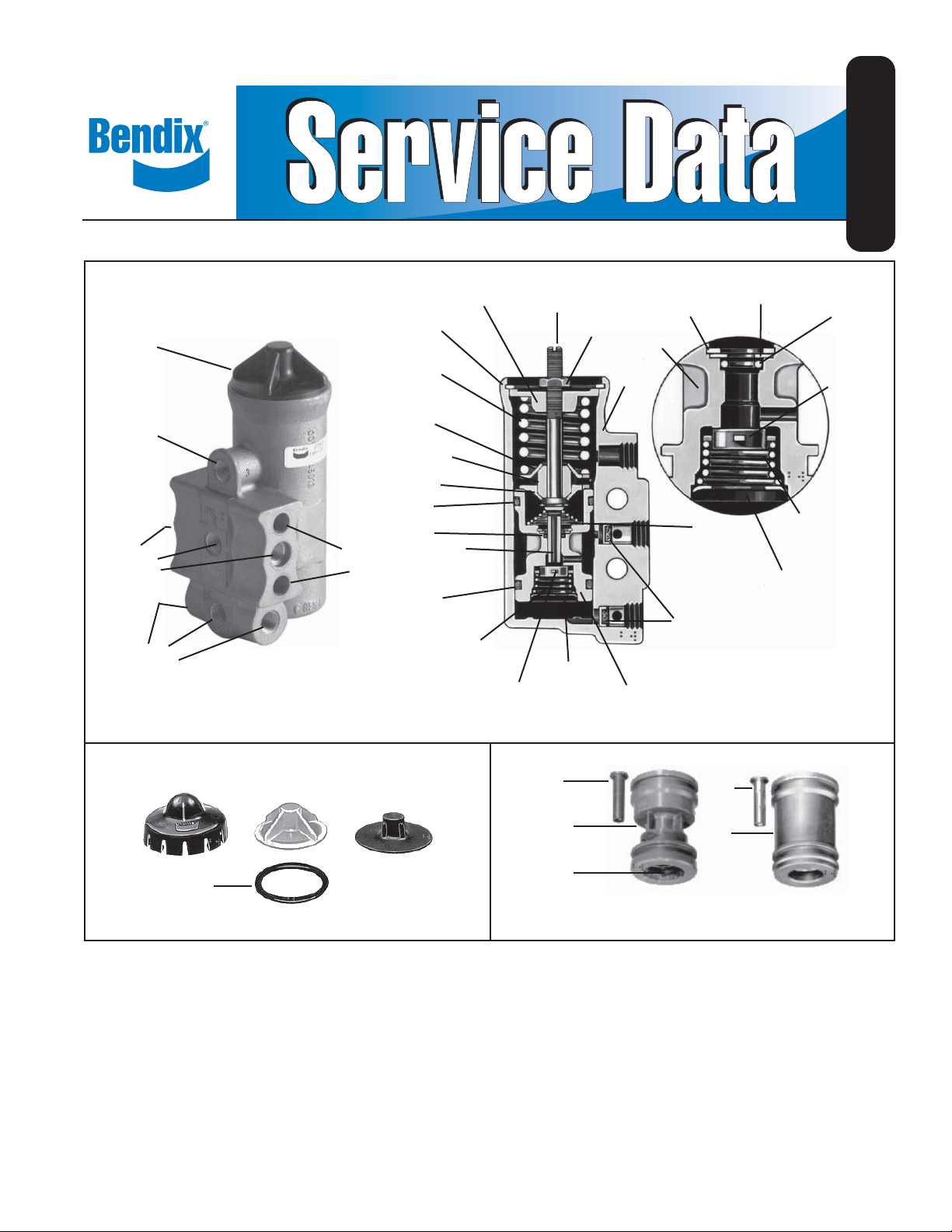
COVER
EXHAUST
PORT
UNLOADER
PORTS (3)
RESERVOIR
PORTS (3)
1
RETAINING RING
17
PRESSURE SETTING
SPRING
19 LOWER
SPRING SEAT
18
SPRING GUIDE
19 LOWER
SPRING SEAT
8 O-RING
12 O-RING
MOUNTING
HOLES
(2)
O-RING
INLET/EXHAUST
VALVE SPRING
FIGURE 1 - D-2® GOVERNOR
16
UPPER SPRING
SEAT
5
EXHAUST
STEM
8
9
10
INLET/EXHAUST
VALVE
4
ADJUSTING
SCREW
15
RETAINING
RING
3
LOCKNUT
BODY
PISTON
2
11
RETAINING
11
PISTON
FILTERS
14
RING
6
EXHAUST
STEM
SPRING
7
13
WASHER
RETAINING
12
O-RING
10
INLET/EXHAUST
VALVE
9
INLET/EXHAUST
COVER VALVE
SPRING
15
RING
BLUE
NONMETALLIC
20
O-RING
CLEAR/BLACK
NONMETALLIC
WITH O-RING
BLACK
RUBBER
FIGURE 2 - TYPES OF COVERS
DESCRIPTION
The Bendix® D-2® governor, operating in conjunction with
the unloading mechanism, automatically controls the air
pressure in the air brake or air supply system between
a maximum (cut-out) pressure and a minimum (cut-in)
pressure. The compressor runs continually while the engine
runs, but the actual compression of air is controlled by the
governor actuating the compressor unloading mechanism
which stops or starts the compression of air when the
maximum or minimum reservoir pressures are reached.
5
11
15
NONMETALLIC METALLIC
5
11
FIGURE 3 - TYPES OF PISTONS
D-2® governors are provided with mounting holes which
allow direct mounting to the compressor or remote
mounting.
Porting consists of three reservoir ports (1/8 inch P.T.),
three unloader ports (1/8 inch P.T.) and one exhaust port
(1/8 inch P.T.).
1

OPERATION
Reservoir air pressure enters the D-2® governor at one of
its reservoir ports and acts on the piston and inlet/exhaust
valve. As the air pressure builds up, the piston and valve
move together against the resistance of the pressure
setting spring. When the reservoir air pressure reaches
the cut-out setting of the governor, the exhaust stem seats
on the inlet/exhaust valve, closing the exhaust passage,
and then opens the inlet passage. Reservoir air pressure
then fl ows around the inlet valve, through the passage in
the piston and out the unloader port to the compressor
unloading mechanism. Air also fl ows around the piston
which is slightly larger at the upper end. The added force
resulting from this larger area assures a positive action
and fully opens the inlet valve.
As the system reservoir air pressure drops to the cutin setting of the governor, the force exerted by the air
pressure on the piston will be reduced so that the pressure
setting spring will move the piston down. The inlet valve will
close and the exhaust will open. With the exhaust open, the
air in the unloader line will escape back through the piston,
through the exhaust stem and out the exhaust port.
Never condemn or adjust the governor pressure settings
unless they are checked with an accurate test gauge
or a dash gauge that is registering accurately. If the
pressure settings of the D-2® governor are inaccurate
or it is necessary that they be changed, the adjustment
procedure follows. Note: If the governor cover is marked
nonadjustable and the adjusting stem has been sheared
off, this is a non-serviceable governor and must be replaced
with a new or remanufactured unit.
A. Remove the top cover from the governor.
B. Loosen the adjusting screw locknut.
C. To raise the pressure settings, turn the adjusting screw
counter-clockwise. T o lower the pressure settings, turn
the adjusting screw clockwise. Note: Be careful not
to over adjust. Each 1/4 turn of the adjusting screw
raises or lowers the pressure setting approximately
4 psi.
D. When proper adjustment is obtained, tighten the
adjusting screw locknut and replace the cover.
(Note: The pressure range between cut-in and cut-out is
not adjustable.)
PREVENTIVE MAINTENANCE
Important: Review the Bendix Warranty Policy before
performing any intrusive maintenance procedures. A
warranty may be voided if intrusive maintenance is
performed during the warranty period.
No two vehicles operate under identical conditions, as
a result, maintenance intervals may vary. Experience is
a valuable guide in determining the best maintenance
interval for air brake system components. At a minimum,
the D-2® governor should be inspected every 6 months
or 1500 operating hours, whichever comes first, for
proper operation. Should the D-2® governor not meet the
elements of the operational tests noted in this document,
further investigation and service of the governor may be
required.
SERVICE TESTS
OPERATING TESTS
Start the vehicle engine and build up air pressure in the air
brake system and check the pressure registered by a dash
or test gauge at the time the governor cuts-out, stopping the
compression of air by the compressor. The cut-out pressure
should be in accordance with the pressure setting of the
piece number being used. (Common cut-out pressures are
between 105-125 psi.) With the engine still running, make
a series of brake applications to reduce the air pressure
and observe at what pressure the governor cuts-in the
compressor. As in the case of the cut-out pressure, the
cut-in pressure should be in accordance with the pressure
setting of the piece number being used. (Common cut-in
pressures are between 90-105 psi.)
2
LEAKAGE TEST
Leakage tests on the D-2® governor should be made in
both cut-in and cut-out positions.
CUT-IN POSITION
Apply soap solution around the cover and to the exhaust
port. Slight bubble leakage permitted. Excessive leakage
indicates a faulty inlet valve or lower piston o-ring.
CUT-OUT POSITION
Apply soap solution around the cover and to the exhaust
port. Slight bubble leakage permitted. Excessive leakage
indicates a faulty exhaust valve seat, exhaust stem o-ring,
or o-ring at the top of the piston.
If the governor does not function as described or leakage is
excessive, it is recommended that it be replaced with a new
or remanufactured unit, or repaired with genuine Bendix
parts available at authorized Bendix parts outlets.
GENERAL SAFETY GUIDELINES
WARNING! PLEASE READ AND FOLLOW
THESE INSTRUCTIONS TO A VOID PERSONAL
INJURY OR DEATH:
When working on or around a vehicle, the
following general precautions should be observed
at all times.
1. Park the vehicle on a level surface, apply the
parking brakes, and always block the wheels.
Always wear safety glasses.
 Loading...