


BA-921
®
BENDIX® BA-921® SMC SINGLE CYLINDER COMPRESSOR FOR
NAVISTAR MAXXFORCE™ 11 AND 13 BIG BORE ENGINES
SD-01-1327
DESCRIPTION
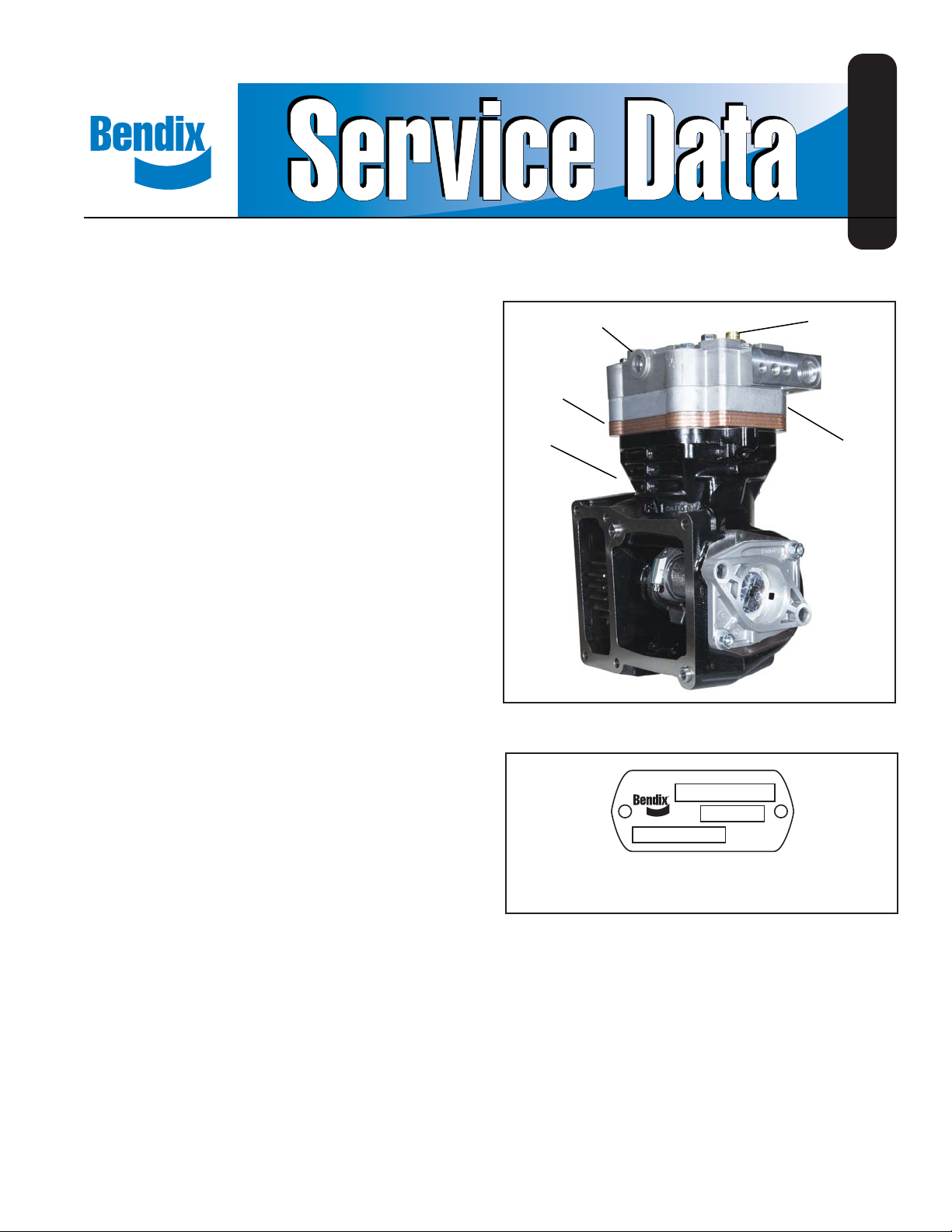
The function of the air compressor is to provide, and
maintain, air under pressure to operate devices in air
brake systems. The Bendix® BA-921® SMC side mount
compressor is a single-cylinder reciprocating compressor
with a rated displacement of 15.8 cubic feet per minute at
1250 RPM.
The compressor consists of a water-cooled cylinder head
assembly and an integral air cooled crankcase assembly .
The cylinder head assembly is made up of the cylinder
head, cooling plate, and valve plate assembly and uses
two sealing gaskets. Both the cylinder head and cooling
plate are aluminum. The cylinder head contains air and
water ports, as well as an unloader assembly. A cooling
plate is located between the cylinder head and valve plate
assemblies and assists in cooling.
The valve plate assembly consists of brazed steel plates
which have valve openings and passages for air and engine
coolant to fl ow into, and out of, the cylinder head. The
compressor's discharge valves are part of the valve plate
assembly . The inlet reed valve/gasket is installed between
the valve plate assembly and the top of the crankcase.
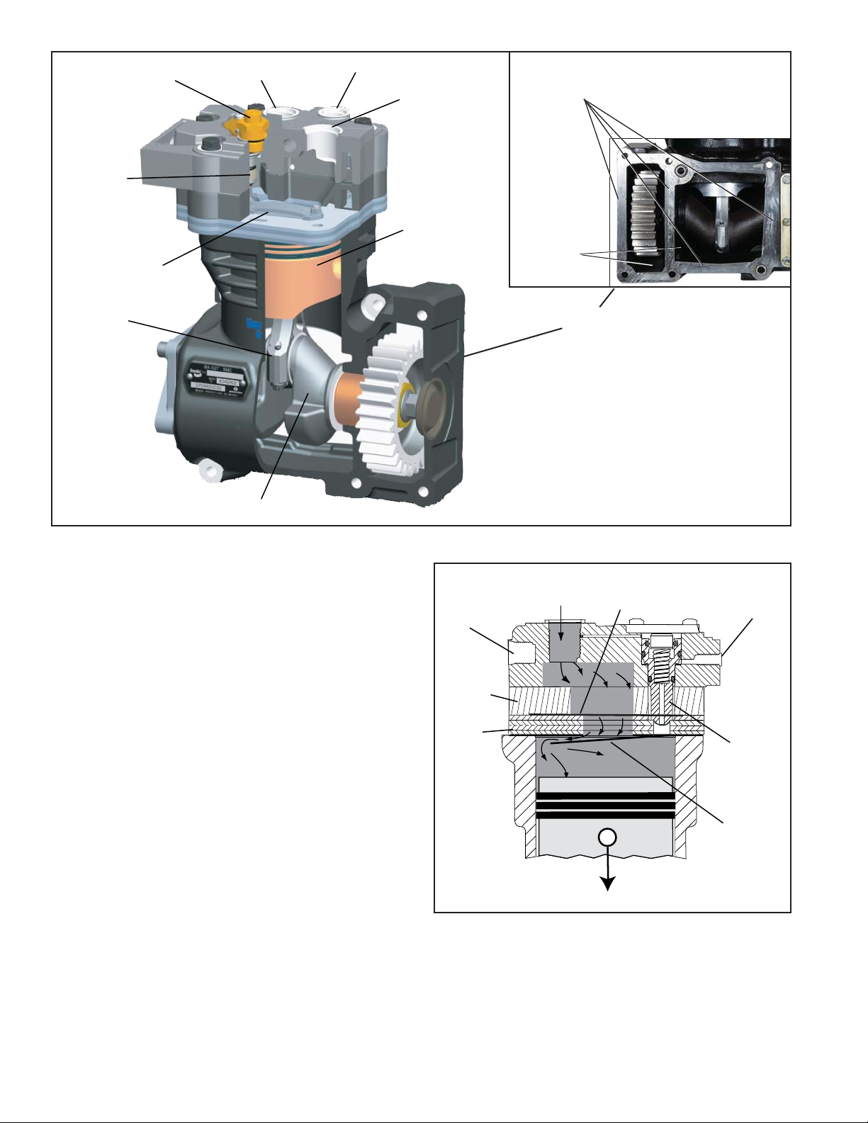
The crankcase has an open side with a machined face and
locating pins. This open face is bolted directly to the side
of the engine block, see Figure 3. The compressor gear
engages the engine drive gear. In addition, the crankcase
houses the piston assembly, connecting rod, crankshaft
and related bearings.
®
The Bendix
a safety valve to protect the compressor head in the event
of, for example, a discharge line blockage downstream
of the compressor. Excessive air pressure will cause the
safety valve to unseat, release air pressure and give an
audible alert to the operator. The safety valve is installed
in the cylinder head safety valve port, directly connected
to the cylinder head discharge port.
BA-921® SMC compressor is equipped with
Cylinder
Head
Valve Plate
Assembly
Crankcase
FIGURE 1 - BENDIX® BA-921® SMC COMPRESSOR
C
A
B
Bendix Part Number . . . . . . A
Customer Piece Number . . . . B
Compressor Serial Number . . C
FIGURE 2 - NAMEPLATE
Safety
Valve
Cooling
Plate
A nameplate is attached to a fl at cast face on the side of
the crankcase. It is stamped with information identifying
the compressor designation, customer piece number,
compressor assembly part number and serial number.
Refer to Figure 2.
Unloader
Piston
Safety
Valve
Discharge
Port
Coolant
Air
Inlet
Port
Piston
Compressor to
engine block
mounting face
Discharge
Reed
Valves (2)
Connecting Rod
Crankshaft
FIGURE 3 - BENDIX® BA-921® SMC COMPRESSOR CUT AWAY VIEW
OPERATION
The compressor is driven by the vehicle's engine, and
functions continuously while the engine is in operation.
Actual compression of air is controlled by the compressor
unloading mechanism operating in conjunction with a
governor.
AIR INTAKE (LOADED)
Just as the piston begins the down stroke, (a position
known as top dead center, or TDC), the vacuum created
in the cylinder bore above the piston causes the inlet reed
valve to fl ex open. Atmospheric air fl ows through the open
inlet valve and fi lls the cylinder bore above the piston. See
Figure 4.
AIR COMPRESSION (LOADED)
When the piston reaches the bottom of the stroke, (a
position known as bottom dead center, or BDC), the inlet
reed valve closes. Air above the piston is trapped by the
closed inlet reed valve and is compressed as the piston
moves upwards. When air in the cylinder bore reaches
a pressure greater than that of the system pressure, the
discharge reed valves open and allow air to fl ow into the
discharge line and air brake system.
Discharge
Cooling
Plate
Valve
Plate
FIGURE 4 - OPERATION - LOADED (INTAKE)
Air
Port
Oil drain
locations
Mounting Face
Air Inlet
Port
Piston Moving Down
Discharge
Valve
Closed
Unloader
Port
Unloader
Piston
Down &
Seated
Inlet
Valve
Open
At the same time air fl ows into the hollow center of the
unloader piston through an opening in the end of the piston.
2
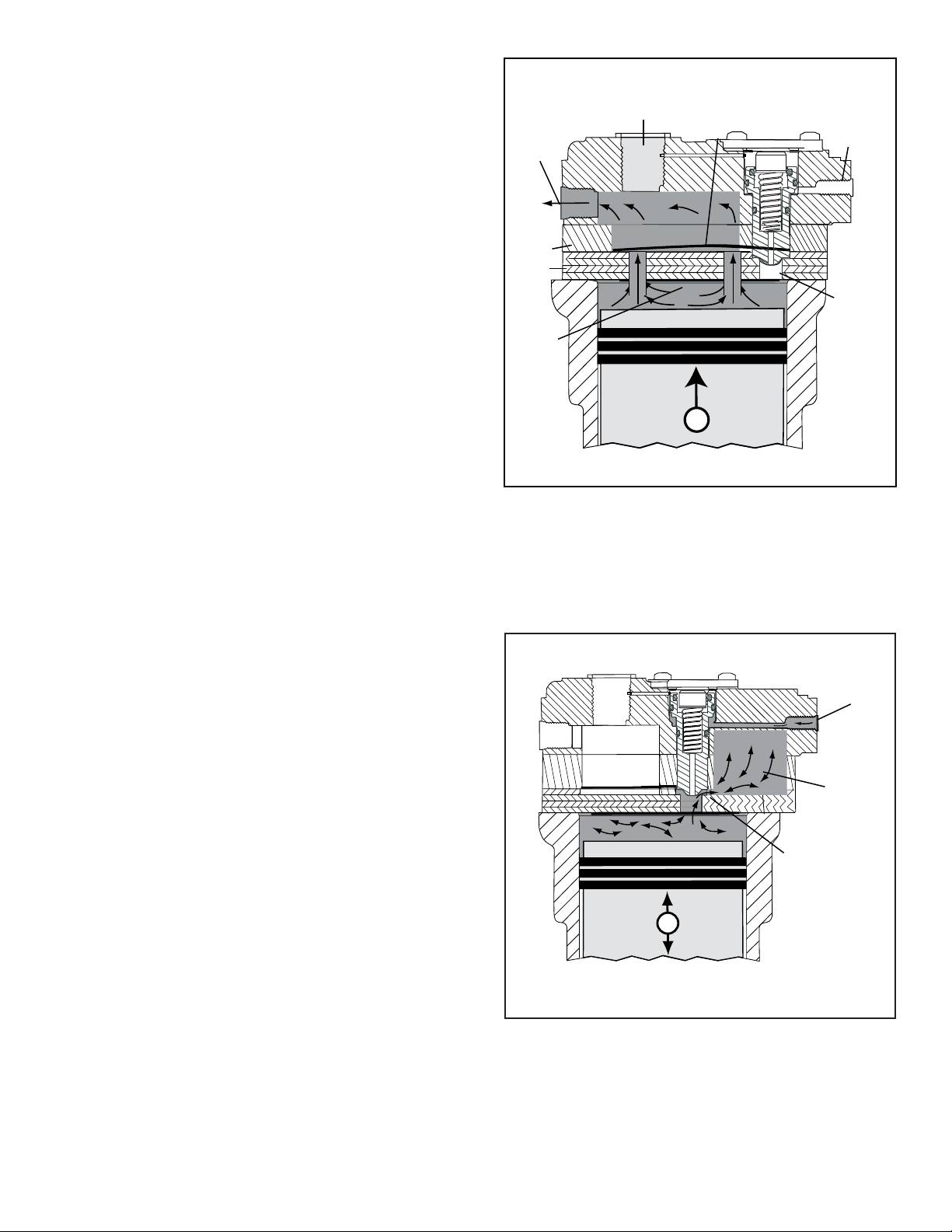
Compressed air acts on the interior surfaces of the unloader
piston and, along with the unloader piston spring, holds the
unloader piston in the down position, against its seat on
the valve plate. See Figure 5.
NON-COMPRESSION OF AIR (UNLOADED)
When air pressure in the supply reservoir reaches the cutout setting of the governor, the governor delivers system air
to the compressor unloader port. Air entering the unloader
port acts on the unloader piston causing the piston to move
away from its seat on the valve plate assembly . When the
unloader piston is unseated, an air passageway is opened
between the cylinder bore and a secondary compartment
or “closed room” in the interior of the cylinder head.
As the piston moves from bottom dead center (BDC) to top
dead center (TDC) air in the cylinder bore fl ows past the
unseated unloader piston, into the “closed room”. The size
of the closed room is suffi cient to accept the compressed
air provided by the compressor piston without creating
excessive air pressure in the “closed room”. On the piston
down stroke (TDC to BDC) air fl ows in the reverse direction,
from the “closed room” past the unseated unloader
piston and inlet reed valve, and into the cylinder bore as
shown in Figure 6. Note: For optimum performance, it is
recommended that the air dryer is equipped with a “turbo
cut-off” feature.
Air Inlet
Air
Discharge
Port
Cooling
Plate
Valve
Plate
Inlet
Valve
Closed
FIGURE 5 - OPERATION - LOADED (COMPRESSION)
Port
Piston Moving Up
Discharge
Valve
Open
Unloader
Port
Unloader
Piston
Down &
Seated
LUBRICATION
The vehicle’s engine provides a continuous supply of
oil to the compressor. Oil is routed from the engine to
the compressor’s oil inlet. Note: There is no external oil
supply line; the oil delivery is located at the engine to
compressor mounting face. This pressurized oil fl ows to
the precision front sleeve main bearing, via an oil passage
in the crankshaft, routes pressurized oil to the connecting
rod bearings and the rear journal associated with the end
cover. Spray lubrication of the cylinder bore and connecting
rod wrist pin bushing is obtained as oil is forced out around
the crankshaft journals by engine oil pressure. Oil then falls
to the bottom of the compressor crankcase and is returned
to the engine through the opening at the compressor
mounting fl ange.
Air From
Governor
Unloader
Port
Closed
Room
Unloader
Piston Up &
Unseated
Air in Pistons Shuttles Back and Forth from the
Piston to the Closed Room
FIGURE 6 - OPERATION - UNLOADED
3
Inlet
Port
Head
Bolt (6)
Coolant
In or Out
Discharge
Safety Valve
Discharge
Port
Coolant
In or Out
Governor
Connection
Unloader
Cover
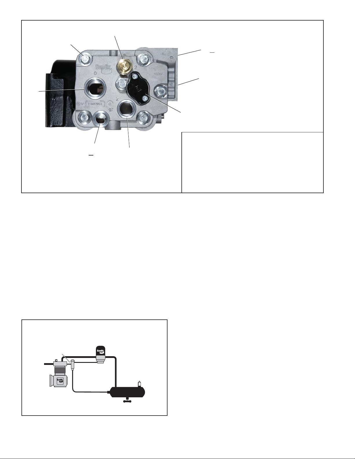
CYLINDER HEAD PORT IDENTIFICATION
The cylinder head connection ports are identifi ed with
cast-in numerals as follows:
AIR IN 0
Compressed AIR OUT 2
Coolant IN or OUT 9
Governor Control 4
FIGURE 7 - BENDIX® BA-921® SMC COMPRESSOR CYLINDER HEAD
COOLING
The Bendix® BA-921® SMC compressor is cooled by air
fl owing through the engine compartment as it passes the
compressor's cast-in cooling fi ns and by the fl ow of engine
coolant through the cylinder head. Coolant supplied by
the engine cooling system passes through connecting
lines into the cylinder head and passes through internal
passages in the cylinder head, cooling plate and valve plate
assembly and returns to the engine. Figure 7 illustrates
the approved coolant fl ow connections. Proper cooling is
important in minimizing discharge air temperatures - see
the tabulated technical data on page 13 of this manual for
specifi c requirements.
AIR INDUCTION
The Bendix® BA-921® SMC compressors is only permitted
to be naturally aspirated – use of engine turbocharger as
an air source is not allowed. See Figure 8 for an example
of a naturally aspirated air induction system.
PREVENTATIVE MAINTENANCE
Regularly scheduled maintenance is the single most
important factor in maintaining the air brake charging
system. Refer to Table A in the Troubleshooting section
starting on page A-1, for a guide to various considerations
that must be given to maintenance of the compressor and
other related charging system components.
Important Note: Review the Bendix
performing any intrusive maintenance procedures. An
extended warranty may be voided if intrusive maintenance
is performed during this period.
Governor
Unloader Port
Air Dryer
EVERY 6 MONTHS, 1800 OPERATING HOURS
OR AFTER EACH 50,000 MILES, WHICHEVER
OCCURS FIRST, PERFORM THE FOLLOWING
Governor
Reservoir
Port
Compressor
INSPECTIONS AND TESTS.
®
Warranty Policy before
FIGURE 8 - COMPRESSOR CHARGING SYSTEM
4

AIR INDUCTION
The Bendix® BA-921® SMC compressor is designed for
connection to the vacuum side of the engine’s air induction
system.
A supply of clean air is one of the single most important
factors in compressor preventive maintenance. Since
®
the air supply for Bendix
BA-921® SMC compressor and
engine is the engine air cleaner, periodic maintenance of
the engine air fi lter is necessary.
Inspect the compressor air induction system each time
engine air cleaner maintenance is performed.
1. Inspect the intake hose adapters for physical damage.
Make certain to check the adapters at both ends of the
intake hose or tubing.
2. Inspect the intake hose clamps and tighten them if
needed.
3. Inspect the intake hose or line for signs of drying,
cracking, chafi ng and ruptures and replace if necessary.
4. Verify that the compressor inlet fi tting is tight (check
torque).
5. Any metal tubes should also be tight (torqued properly)
to the mating fi tting. Inspect the metal tubes for any
cracks or breaks and replace if necessary.
COMPRESSOR COOLING
Inspect the compressor discharge port, inlet cavity and
discharge line for evidence of restrictions and carbon
build-up. If more than 1/16" of carbon is found, thoroughly
clean or replace the affected parts. In some case, carbon
build-up indicates inadequate cooling. Closely inspect the
compressor cooling system. Check all compressor coolant
lines for kinks and restrictions to fl ow. Minimum coolant line
size is 3/8" I.D. Check coolant lines for internal clogging
from rust scale. If coolant lines appear suspicious, check
the coolant fl ow and compare to the tabulated technical
data present in the back of this manual. Carefully inspect
the air induction system for restrictions.
LUBRICATION
The compressor utilizes an internal oil feed design. Check
the exterior of the compressor (i.e. around the mounting
face) for the presence of oil seepage and refer to the
Troubleshooting section for appropriate tests and corrective
action. Refer to the tabulated technical data in the back of
this manual for oil pressure minimum values.
If compressor oil passing is suspected, refer to the
Troubleshooting section (starting on page A-1) for the
symptoms and corrective actions to be taken. In addition,
Bendix has developed the “Bendix Air System Inspection
Cup”, or Bendix
®
BASIC™ kit, to help substantiate
suspected excessive oil passing. The steps to be followed
™
when using the BASIC
kit are presented in APPENDIX
B, on page A-16.
COMPRESSOR DRIVE
Check for noisy compressor operation, which could indicate
excessive drive component wear. Adjust and/or replace
as necessary. Check all compressor mounting bolts and
retighten evenly if necessary . Check for leakage. Repair
or replace parts as necessary.
COMPRESSOR UNLOADER & GOVERNOR
Test and inspect the compressor and governor unloader
system for proper operation and pressure setting.
1. Check for leakage at the unloader port. Replace leaking
or worn o-rings.
2. Make certain the unloader system lines are connected
as illustrated in Figure 8.
3. Cycle the compressor through the loaded and unloaded
cycle several times. Make certain that the governor
cuts-in (compressor resumes compressing air) at a
minimum of 105 psi (cut-out should be approximately
15 - 20 psi greater than cut-in pressure). Adjust or
replace the governor as required.
4. Note that the compressor cycles to the loaded and
unloaded conditions promptly. If prompt action is not
noted, repair or replace the governor and/or repair the
compressor unloader.
IMPORTANT NOTE
Replacement air governors must have a minimum cut-in
pressure of 100 psi. The cut-in pressure is the lowest
system pressure registered in the gauges before the
compressor resumes compressing air.
Compressors with no signal line to the unloader port should
have a vent cap (e.g. Bendix P/N 222797) installed in the
port. Under no circumstances should the port be plugged
or left open.
OIL PASSING
All reciprocating compressors pass a minimal amount of
oil. Air dyers will remove the majority of oil before it can
enter the air brake system. For particularly oil sensitive
systems, the Bendix® PuraGuard® system can be used in
conjunction with a Bendix® air dryer.
5

SERVICE TESTS
LEAKAGE TESTS
GENERAL
The compressor operating and leakage tests listed below
need not be performed on a regular basis. These tests
should be performed when it is suspected that leakage is
substantially affecting compressor build-up performance,
or when it is suspected that the compressor is “cycling”
between the loaded (pumping) and unloaded (nonpumping) modes due to unloader leakage.
IN SERVICE OPERATING TESTS
Compressor Performance: Build-up Test
This test is performed with the vehicle parked and the
engine operating at maximum recommended governed
speed. Fully charge the air system to governor cut-out (air
dryer purges). Pump the service brake pedal to lower the
system air pressure below 80 psi using the dash gauges.
As the air pressure builds back up, measure the time from
when the dash gauge passes 85 psi to the time it passes
100 psi. The time should not exceed 40 seconds. If the
vehicle exceeds 40 seconds, test for (and fi x) any air leaks,
and then re-test the compressor performance. If the vehicle
does not pass the test the second time, use the Advanced
Troubleshooting Guide for Air Brake Compressors, starting
on page A-1 of this document to assist your investigation
of the cause(s).
See the standard Air Brake System and Accessory Leakage
test on Page A-14 (Test 2).
Note: Leakage in the air supply system (components
before the supply reservoir such as the governor, air dryer ,
reservoir drain cocks, safety valve, and check valves) will
not be registered on the vehicle dash gauges and must
be tested separately. Refer to the various maintenance
manuals for individual component leakage tests and the
Bendix “Test and Checklist” published in the Bendix
Brake System Handbook (BW5057) and on the back of
the Bendix Dual Circuit Brake System Troubleshooting
Card (BW1396).
Air
CYLINDER HEAD
Check for cylinder head gasket air leakage.
1. With the engine running, lower air system pressure to 60
psi and apply a soap solution around the cylinder head.
Check the gasket between the cylinder head and valve
plate assembly, as well as the inlet reed valve/gasket
between the valve plate assembly and crankcase for
air leakage.
2. No leakage is permitted. If leakage is detected, replace
the compressor or repair the cylinder head using a
genuine Bendix® maintenance kit available from an
authorized Bendix® parts outlet.
Note: All new vehicles are certifi ed using the FMVSS
121 test (paragraph S5.1.1) by the vehicle manufacturer,
however the above test is a useful guide for in-service
vehicles.
Optional Comparative Performance Check
It may be useful to also conduct the above test with the
engine running at high idle (instead of maximum governed
speed), and record the time required to raise the system
pressure a selected range (for example, from 90 to 120 psi,
or from 100 to 120 psi, etc.) in the vehicle’s maintenance
fi les. Subsequent build-up times throughout the vehicle’s
service life can then be compared to the fi rst one recorded.
(Note: the 40 second guide in the test above does not
apply to this build-up time.) If the performance degrades
significantly over time, you may use the Advanced
Troubleshooting Guide for Air Brake Compressors, starting
on page A-1 of this document, to assist investigation of
the cause(s).
Note: When comparing build-up times, be sure to make
an allowance for any air system modifi cations which would
cause longer times, such as adding air components or
reservoirs. Always check for air system leakage.
INLET, DISCHARGE & UNLOADER
In order to test the inlet and discharge valves and the
unloader piston, it is necessary to have shop air pressure
and an assortment of fi ttings. A soap solution is also
required.
1. With the engine shut off, drain ALL air pressure from
the vehicle.
2. Disconnect the inlet and discharge lines and remove
the governor or its line or adapter fi tting.
3. Apply 120-130 psi shop air pressure to the unloader
port and soap the inlet port. Leakage at the inlet port
should not exceed 50 sccm.
4. Apply 120-130 psi shop air pressure to the discharge
port and then apply and release air pressure to the inlet
port. Soap the inlet port and note that leakage at the
inlet port does not exceed 20 sccm.
If excessive leakage is noted in Tests 3 or 4, replace or
repair the compressor using genuine Bendix® replacements
or maintenance kits available from any authorized Bendix
parts outlet.
6

While it is possible to test for inlet, discharge, and unloader
piston leakage, it may not be practical to do so. Inlet and
discharge valve leakage can generally be detected by longer
compressor build-up and recovery times. Compare current
compressor build-up times with the last several recorded
times. Make certain to test for air system leakage, as
described under In Service Operating Tests, before making
a determination that performance has been lost.
Unloader leakage is generally exhibited by excessive
compressor cycling between the loaded and unloaded
condition.
1. With service and supply system leakage below the
maximum allowable limits and the vehicle parked, bring
system pressure to governor cut-out and allow the engine
to idle.
2. The compressor should remain unloaded for a minimum
of 5-10 minutes. If compressor cycling occurs more
frequently and service and supply system leakage is
within tolerance, replace the compressor or repair the
compressor unloader system using a genuine Bendix
maintenance kit available from authorized Bendix parts
outlets.
®
COMPRESSOR REMOVAL & DISASSEMBLY
GENERAL
The following disassembly and assembly procedure is
presented for reference purposes and pre-supposes that
a rebuild or repair of the compressor is being undertaken.
Several maintenance kits are available and the instructions
provided with these parts and kits should be followed in lieu
of the instructions presented here.
MAINTENANCE KITS & SERVICE PARTS FOR
BENDIX
COMPRESSOR ONLY
Cylinder Head Gasket Kit ...................................K023764
Unloader Kit ........................................................K046477
Discharge Safety Valve ......................................800534
Compressor Seal Kit...........................................K051352
Compressor to Engine Mounting Face Sealant (Supplied by
the Engine Manufacturer)
All components shown in Figure 9 with a key number are
available in kits and/or as individual service parts.
®
BA-921® SMC SINGLE CYLINDER
GENERAL SAFETY GUIDELINGS
IMPORTANT! PLEASE READ AND FOLLOW
THESE INSTRUCTIONS TO AVOID PERSONAL
INJURY OR DEATH:
When working on or around a vehicle, the following
general precautions should be observed at all times:
1. Park the vehicle on a level surface, apply the
parking brakes, and always block the wheels.
Always wear safety glasses. Where specifi cally
directed, the parking brakes may have to be
released, and/or spring brakes caged, and this
will require that the vehicle be prevented from
moving by other means for the duration of these
tests/procedures.
2. Stop the engine and remove ignition key when
working under or around the vehicle. When
working in the engine compartment, the engine
should be shut off and the ignition key should
be removed. Where circumstances require
that the engine be in operation, EXTREME
CAUTION should be used to prevent personal
injury resulting from contact with moving,
rotating, leaking, heated or electrically charged
components.
3. Do not attempt to install, remove, disassemble
or assemble a component until you have read
and thoroughly understand the recommended
procedures. Use only the proper tools and
observe all precautions pertaining to use of those
tools.
4. If the work is being performed on the vehicle’s
air brake system, or any auxiliary pressurized air
systems, make certain to drain the air pressure
from all reservoirs before beginning ANY work
on the vehicle. If the vehicle is equipped with
a Bendix® AD-IS® air dryer system or a dryer
reservoir module, be sure to drain the purge
reservoir.
5. Following the vehicle manufacturer’s
recommended procedures, deactivate the
electrical system in a manner that safely removes
all electrical power from the vehicle.
6. Never exceed manufacturer’s recommended
pressures.
7. Never connect or disconnect a hose or line
containing pressure; it may whip. Never remove
a component or plug unless you are certain all
system pressure has been depleted.
8. Use only genuine Bendix® brand replacement
parts, components and kits. Replacement
hardware, tubing, hose, fi ttings, etc. must be
of equivalent size, type and strength as original
equipment and be designed specifi cally for such
applications and systems.
7

9. Components with stripped threads or damaged
parts should be replaced rather than repaired. Do
not attempt repairs requiring machining or welding
unless specifi cally stated and approved by the
vehicle and component manufacturer.
10. Prior to returning the vehicle to service, make
certain all components and systems are restored
to their proper operating condition.
11. For vehicles with Automatic T raction Control (A TC),
the ATC function must be disabled (ATC indicator
lamp should be ON) prior to performing any vehicle
maintenance where one or more wheels on a drive
axle are lifted off the ground and moving.
REMOVAL
In many instances it may not be necessary to remove the
compressor from the vehicle when installing the various
maintenance kits and service parts. The maintenance
technician must assess the installation and determine
the correct course of action. These instructions are
general and are intended to be a guide. In some cases
additional preparations and precautions are necessary.
In all cases follow the instructions contained in the vehicle
maintenance manual in lieu of the instructions, precautions
and procedures presented in this manual.
1. Block the wheels of the vehicle and drain the air
pressure from all the reservoirs in the system.
2. Drain the engine cooling system and the cylinder head
of the compressor. Identify and disconnect all air , water
and oil lines leading to the compressor.
3. Remove as much road dirt and grease from the exterior
of the compressor as possible.
4. Remove the discharge fi tting, if applicable, and note
their position on the compressor to aid in reassembly.
5. Remove any supporting bracketing attached to the
compressor and note their positions on the compressor
to aid in reassembly.
6. Remove the six mounting bolts that retain the
compressor to the side of the engine block. Note
the position of the six mounting bolts. Two of the six
bolts are shorter and must be installed in their original
locations. Remove the compressor from the vehicle.
7. Inspect drive gear and associated drive parts for visible
wear or damage. If the compressor drive gear is worn
or damaged, the compressor must be replaced. Refer
to the Engine Manufacturers service manual to address
the associated engine drive parts.
8. If the compressor is being replaced stop here and
proceed to “Installing the Compressor” at the end
of the assembly procedure. (Note: Replacement
compressors come with the drive gear pre-assembled
on the compressor.)
PREPARATION FOR DISASSEMBLY
Refer to Figure 9 during the entire disassembly and
assembly procedure.
Place a clean rag over the openings that expose the
gear and crankshaft / connecting rod assembly. No
contamination is permitted in these areas.
Remove the balance of the road dirt and grease from the
exterior of the compressor with a cleaning solvent. If the
rear end cover is being removed from the compressor
under repair, mark it, along with the two cap screws, in
relation to the crankcase. It is also recommended to mark
the relationship of the cylinder head, cooling plate, valve
plate assembly, and crankcase.
A convenient method to indicate the above relationships
is to use a metal scribe to mark the parts with numbers or
lines. Do not use marking methods, such as chalk, that
can be wiped off or obliterated during rebuilding.
Prior to disassembly, make certain that the appropriate
kits are available.
CYLINDER HEAD
1. Remove the discharge safety valve (9) from the cylinder
head.
2. To restrain the spring force exerted by the return spring
(3) of the unloader assembly, hold the unloader cover
in place while removing the two unloader cover cap
screws. Carefully release the hold on the unloader
cover until the spring force is relaxed, then remove the
unloader cover.
3. Remove the unloader cover gasket (4).
4. Remove the balance piston (5) with its o-ring (6); return
spring (3) and the unloader piston assembly (7) which
includes the unloader piston, two outer o-rings and two
guide bushings from the cylinder head.
5. Remove the six hex head bolts from the cylinder head.
Note: The fi ve hex bolts located towards the perimeter
of the cylinder head retain the cylinder head directly to
the crankcase. The single hex bolt in the center of the
cylinder head holds the cylinder head, cooling plate
and valve plate assembly together; independent of the
crankcase.
6. Gently tap the cylinder head, cooling plate and valve
plate assembly with a soft mallet to break the gasket
seal between the valve plate assembly and the
crankcase. Lift the cylinder head with cooling plate
and valve plate assembly off the crankcase.
7. Remove the metal inlet reed valve/gasket (1).
8
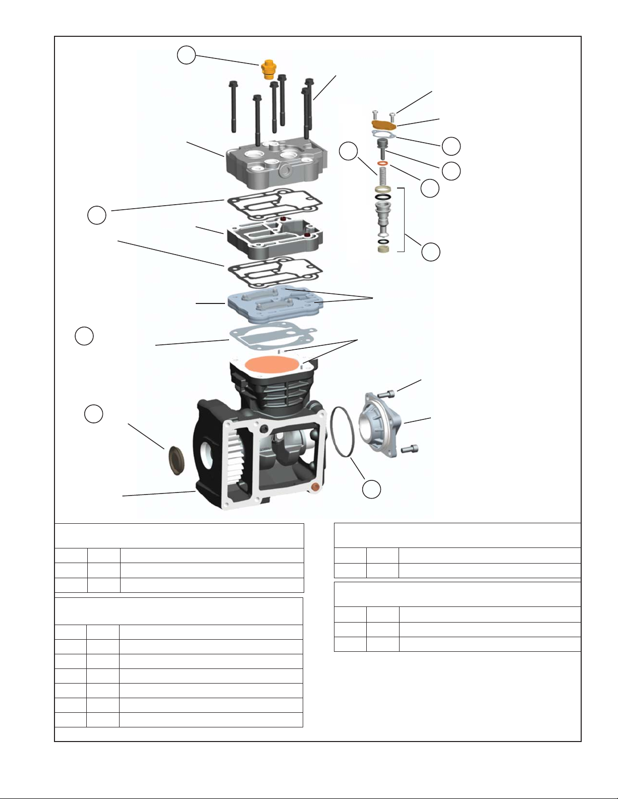
Note: Always
Replace Safety
Valve in Original
Location
2
Cylinder Head
Gasket
(2)
9
™
ST-4
Safety
Valve
Cylinder Head
Cooling
Plate
Valve Plate
Assembly
Cylinder Head Cap Screws (6)
(includes washers)
Return
Spring
3
Balance Piston
Unloader Piston
Assembly
Alignment
Bushings
Unloader Cover
Cap Screws
Unloader
Cover
Unloader Cover
Gasket
4
Balance
5
Piston
6
O-Ring
7
1
Inlet Reed Valve/
Gasket
11
Cover
Crankcase
CYLINDER HEAD GASKET KIT PIECE NO. K023764
CONSISTS OF THE FOLLOWING:
ITEM QTY DESCRIPTION
1 1 INLET REED VALVE GASKET
2 2 CYLINDER HEAD GASKET
UNLOADER KIT PIECE NO. K046477 CONSISTS OF
THE FOLLOWING:
ITEM QTY DESCRIPTION
3 1 RETURN SPRING
4 1 UNLOADER COVER GASKET
5 1 BALANCE PISTON
6 1 BALANCE PISTON O-RING
7 1 UNLOADER PISTON ASSEMBLY
8 1 LUBRICANT (NOT SHOWN)
Crankcase
Alignment Pins
End Cover
Screws
End Cover
10
End Cover
O-ring
SAFETY VALVE KIT PIECE NO. 800534 CONSISTS OF
THE FOLLOWING:
ITEM QTY DESCRIPTION
™
9 1 ST-4
SAFETY VALVE
CRANKCASE SEAL KIT PIECE NO. K051352 CONSISTS
OF THE FOLLOWING:
ITEM QTY DESCRIPTION
10 1 END COVER O-RING
11 1 COVER
FIGURE 9 – BA-921® CLOSED ROOM COMPRESSOR EXPLODED VIEW.
9
8. Gently tap the cylinder head, cooling plate and valve
plate assembly with a soft mallet to break the gasket
seals. Then separate the cylinder head from the cooling
plate and valve plate assembly and remove the two
gaskets (2) between them.
CRANKCASE FRONT COVER
1. Remove the cover (1 1) from the front of the crankcase.
Use a sharp fl at head screw driver or a scraper. Place
the edge under the lip along the outside diameter of
the cover. Pry the cover from the cast surface until the
cover can be removed.
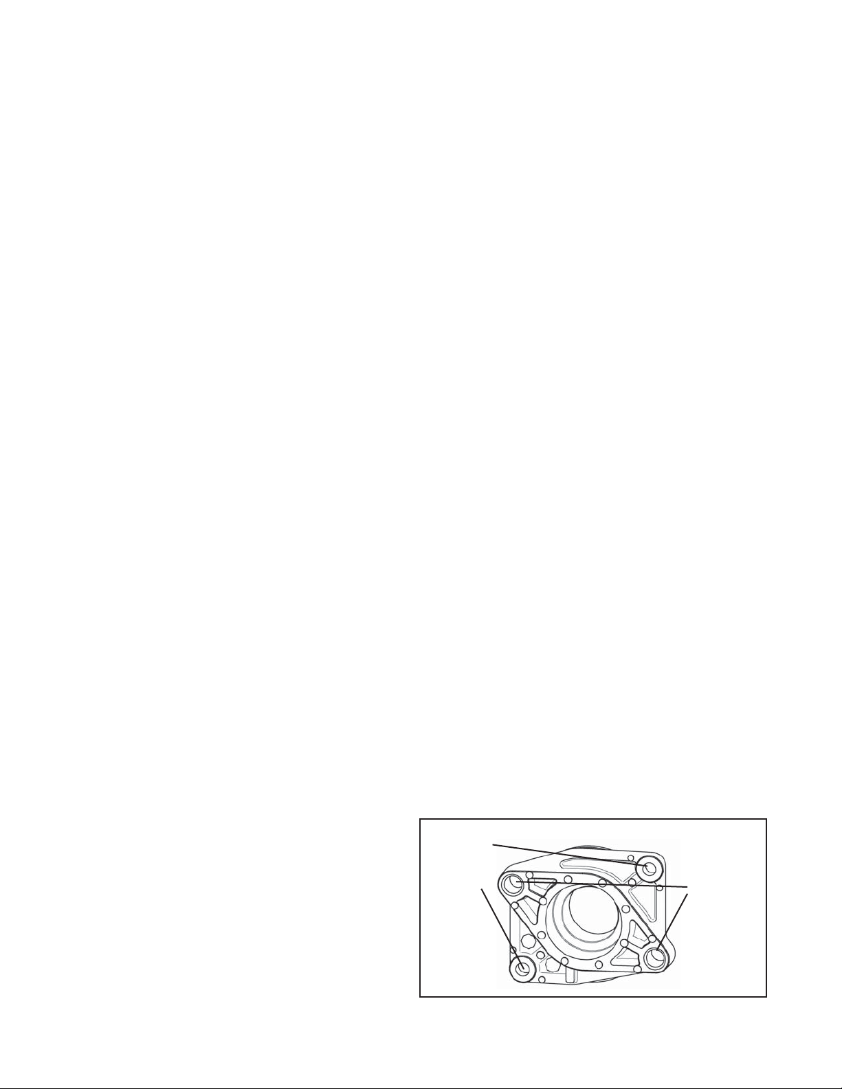
REAR END COVER
1. Note: There are two cap screws used to retain the
end cover to the crankcase. There are two longer cap
screws (not shown in Figure 10) that are used to retain
the auxiliary drive unit (i.e. hydraulic pump) via the end
cover and torqued into the crankcase. If the auxiliary
drive unit has already been removed, these two cap
screws are no longer present on the end cover. Refer
to Figure 9 to see location of the cap screws in the end
cover.
2. Remove the two end cover cap screws that secure the
rear end cover to the crankcase.
3. Remove the rear end cover from the crankcase.
Remove and discard the o-ring (10) from the end cover.
CLEANING OF PARTS
GENERAL
All parts should be cleaned in a good commercial grade of
solvent and dried prior to inspection.
CRANKCASE
1. Carefully remove all sealant gasket material adhering
to the machined face of the crankcase. See Figure
3. Make certain not to scratch or mar the mounting
surface. Note: Keep the crankcase opening covered
to prevent any of the sealant material from entering.
Repeat this process on the engine mounting face as
well. Follow the instructions contained in the vehicle
maintenance manual in lieu of the instructions and
procedures presented in this manual.
2. Carefully remove all gasket material adhering to the
deck (top) of the crankcase. Remove any carbon
deposits from the deck of the crankcase. Make certain
not to scratch or mar the gasket surfaces.
CYLINDER HEAD ASSEMBLY
1. Carefully remove all gasket material adhering to the
cylinder head, cooling plate, valve plate assembly and
cast iron crankcase. Make certain not to scratch or
mar the gasket surfaces. Pay particular attention to
the gasket surfaces of the head.
2. Remove carbon deposits from the discharge and inlet
cavities of the cylinder head, cooling plate and valve
plate assembly. They must be open and clear in both
assemblies. Make certain not to damage the head.
3. Remove rust and scale from the cooling cavities and
passages in the cylinder head, cooling plate and valve
plate assembly and use shop air to clear debris from
the passages.
4. Check the threads in all cylinder head ports for
galling (e.g. abrasion, chafi ng). Minor thread chasing
(damage) is permitted.
5. Remove any carbon or old grease from the two bores
in the unloader cavity of the cylinder head.
INSPECTION OF PARTS
CYLINDER HEAD, COOLING PLATE, VALVE
PLATE A SSEMBLY AND UNLOADER MECHANISM
1. Carefully inspect the head gasket surfaces on the
cylinder head for deep gouges and nicks. Also, inspect
the cylinder head for any cracks or port thread damage.
If detected, the compressor must be replaced. If large
amounts of carbon build-up are present in the discharge
cavity, such that it restricts the air fl ow through the
cylinder head, the compressor should be replaced.
2. Carefully inspect both sides of the head gasket
surfaces on the cooling plate for deep gouges and
nicks. Also, inspect the cooling plate for any cracks
or other damage. If cracks or damage are found, the
compressor must be replaced.
3. Carefully inspect the valve plate assembly gasket
surfaces (both sides) for deep gouges and nicks.
Pay particular attention to the gasket surface. An
inlet reed valve/gasket (1) is used between the valve
plate assembly and crankcase. This gasket surface
must be smooth and free of all but the most minor
scratches. If excessive marring or gouging is detected,
the compressor must be replaced. If large amounts of
carbon build-up are present on the two main surfaces, in
the two discharge valve holes or between the discharge
valve and the discharge seat, the compressor should
be replaced.
M8x1.25
Cap
Screws
(Smaller)
FIGURE 10 - REAR END COVER ATTACHMENT BOLTS
M10x1.5
Cap
Screws
(Larger)
10

4. If the unloader assembly has been removed from the
cylinder head, the unloader assembly must be serviced
using an unloader kit. (See Maintenance Kits, page 9.)
5. If large amounts of carbon build-up are present on the
unloader piston (7) seat or orifi ce or if the return spring
exhibits compression set, the unloader components
must be replaced with an unloader kit.
6. Carefully inspect the 2 bores in the unloader cavity of
the cylinder head for gouges or material transfer. If this
is detected, the compressor should be replaced.
REAR END COVER
Visually inspect for cracks and external damage. Check the
crankshaft rear bearing diameter in the rear end cover for
excessive wear, fl at spots or galling. Check the hydraulic
pump attachment pilot and threaded holes for damage.
Minor thread chasing is permitted, but do not re-cut the
threads. If any of these conditions are found, replace the
compressor.
CRANKCASE
Check the cylinder head gasket surface on the deck (top)
of the crankcase for nicks, gouges, and marring. A metal
gasket is used to seal the cylinder head to the crankcase.
This surface must be smooth and free of all but the most
minor scratching. If excessive marring or gouging is
detected, the compressor must be replaced.
Check the condition of the countersunk hole on the deck
of the crankcase that retains the o-ring and prevents
coolant leakage between the valve plate assembly and the
crankcase. The surface in contact with the o-ring should
be smooth and free of any scratches and gouges that could
causes leakage around the o-ring.
ASSEMBLY
General Note: All torques specifi ed in this manual are
assembly torques and typically can be expected to fall off
after assembly is accomplished. Do not re-torque after
initial assembly torques fall unless instructed otherwise.
A compiled listing of torque specifi cations is presented on
page 13.
INCH POUNDS TO FOOT POUNDS
To convert inch pounds to foot pounds of torque, divide
inch pounds by 12.
Example: 12 Inch Pounds = 1 Foot Pound
12
FOOT POUNDS TO INCH POUNDS
To convert foot pounds to inch pounds of torque, multiply
foot pounds by 12.
Example: 1 Foot Pound x 12 = 12 Inch Pounds
CRANKCASE FRONT COVER
1. Position the new cover over the hole in the front of the
crankcase. Using a rubber mallet, drive the cover into
the hole in the front of the crankcase, until the outside
diameter of the cover is fl ush with cast surface.
REAR END COVER
1. Install the o-ring (10) on the rear end cover.
2. Orient the rear end cover to the crankcase using the
reference marks made during disassembly. Carefully
install the rear end cover in the crankcase making
certain not to damage the crankshaft bearing surface.
3. Install the two end cover cap screws. Refer to Figure
10 to assure that the two cap screws are installed in
the proper crankcase bolt holes. “Snug” the screws
then tighten to 195 to 212 inch pounds (22-24 N•m).
CYLINDER HEAD ASSEMBLY
PART ONE: HEAD INSTALLATION
1. Note the position of the protruding alignment pins on
the deck (top) of the crankcase. Install the metal inlet
reed valve/gasket (1) over the alignment pins on the
crankcase.
2. Position the valve plate assembly on the crankcase
so that the alignment pins in the crankcase fi t into the
corresponding holes in the valve plate assembly.
3. Position and install one of the embossed metal gaskets
(2) over the alignment bushings protruding from the
cooling plate. Position and install the second embossed
metal gasket (2) over the alignment bushings on the
opposite side of the cooling plate. When properly
installed, the outline of the two embossed gaskets
match the outline of the cooling plate.
4. Install the cooling plate onto the valve plate assembly
by lining up the alignment bushings on the cooling plate
over the oversized countersunk holes of the valve plate
assembly . Again, when properly installed, the outline of
the cooling plate matches the outline of the valve plate.
5. Position and install the cylinder head over the alignment
bushings protruding from the cooling plate. When
properly installed, the outline of the cylinder head
assembly will match the outline of the cooling plate and
valve plate assembly.
Note: The alignment bushings will only fi t into two of
the cylinder head bolt holes.
6. Install the six hex head cylinder head bolts and washers
and snug them (fi nger tight), then torque the bolts in
the sequence specifi ed in Figure 11. Note: A light fi lm
of oil should be applied to the thread of these bolts prior
to installation. Oil should not be applied to any other
bolts.
11
 Loading...