

Page 1
®
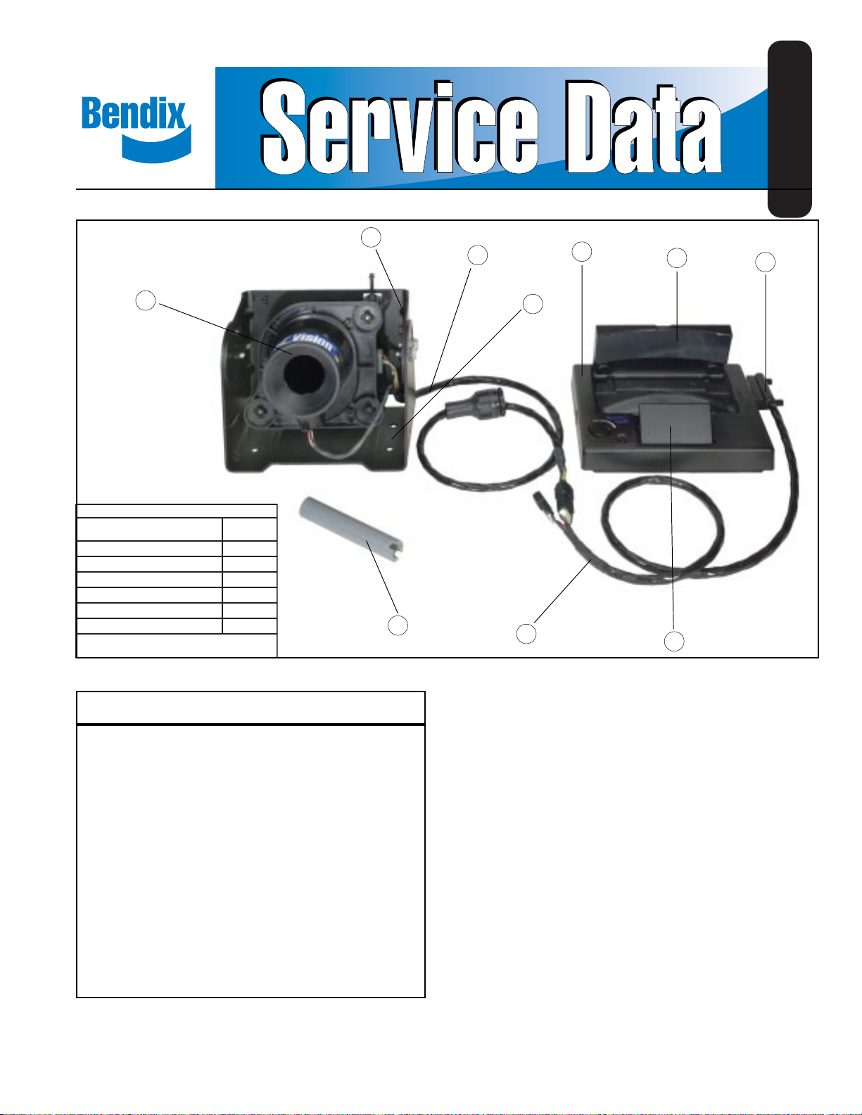
Bendix® XVision® System
SD-19-5160
2
3
5
6
7
1
®
noisiVX
traP/tiK
tiKtekcarBaremaC8700105
)tnuoMBC(tiKgnitnuoM1800105
tiKssenraH3800105
looTretsujdAgnimiA*
:fostsisnoc)6800105(metsyS
eceiP
rebmuN
)egniHnoitcirF(tiKgnitnuoM2800105
noitanibmoCyalpsiD/aremaC*
ebtonnacdnaelbaecivestonsitraP/tiK*
.xidneBhguorhtderedroyllaudividni
10
4
9
8
.oNmetInoitpircseD.ytQ
1aremaCRI1
2tekcarBaremaCRI1
3ssenraHaremaCRI1
4tekcarBgnitnuoM1
5yalpsiD1
6renibmoC1
7rotcennoCniP-521
8rorriMdloF1
9**ssenraHyalpsiD2
01looTretsujdAgnimiA1
.)rosiv(tnuomegnihnoitcirfehtrofsinwohsssenrahyalpsidehT**
Figure 1 XVision® System
1
Page 2

NOTE: The information in this Service Data is correct and complete as of the time of printing. Options or updates to the
XVision
®
System that were developed after publication may not be included.
TABLE OF CONTENTS
SAFE MAINTENANCE PRACTICES 3
INTRODUCTION 3
COMPONENTS 3
IR CAMERA BRACKET KIT 4
CB STYLE MOUNTING KIT 5
FRICTION HINGE MOUNTING KIT 5
HARNESS KIT 6
AIMING ADJUSTER TOOL 8
IR CAMERA/DISPLAY COMBINATION 8
REPLACEMENT KITS 9
AIMING ADJUSTER REPLACEMENT 9
WINDOW REPLACEMENT 9
HEATER REPLACEMENT 9
COMBINER MIRROR REPLACEMENT 9
FOLD MIRROR REPLACEMENT 9
ELECTRICAL SYSTEM 10
POWER AND GROUND (INPUTS) 10
OPERATING INPUT VOLTAGE 10
SERVICING THE XVISION
MOUNTING BRACKET 11
IR CAMERA BRACKET 11
IR CAMERA 12
IR CAMERA WINDOW 14
IR CAMERA WINDOW HEATER 15
DISPLAY 16
COMBINER 16
FOLD MIRROR 16
DISPLAY BRACKET 17
DISPLAY REPLACEMENT 18
HARNESSES 18
AIMING THE IR CAMERA 21
HORIZONTAL AIMING 21
VERTICAL AIMING 22
TROUBLESHOOTING 24
®
SYSTEM 11
2
Page 3

SAFE MAINTENANCE PRACTICES
WARNING! PLEASE READ AND FOLLOW
THESE INSTRUCTIONS TO AVOID
PERSONAL INJURY OR DEATH:
When working on or around a vehicle, the following
general precautions should be observed at all times.
1. Park the vehicle on a level surface, apply the
parking brakes, and always block the wheels.
Always wear safety glasses.
2. Stop the engine and remove ignition key when
working under or around the vehicle. When
working in the engine compartment, the engine
should be shut off and the ignition key should be
removed. Where circumstances require that the
engine be in operation,
be used to prevent personal injury resulting from
contact with moving, rotating, leaking, heated or
electrically charged components.
3. Do not attempt to install, remove, disassemble or
assemble a component until you have read and
thoroughly understand the recommended
procedures. Use only the proper tools and observe
all precautions pertaining to use of those tools.
4. If the work is being performed on the vehicle’s air
brake system, or any auxiliary pressurized air
systems, make certain to drain the air pressure from
all reservoirs before beginning ANY work on the
vehicle. If the vehicle is equipped with an AD-IS
air dryer system or a dryer reservoir module, be
sure to drain the purge reservoir.
5. Following the vehicle manufacturer’s
recommended procedures, deactivate the electrical
system in a manner that safely removes all electrical
power from the vehicle.
6. Never exceed manufacturer’s recommended
pressures.
7. Never connect or disconnect a hose or line
containing pressure; it may whip. Never remove a
component or plug unless you are certain all
system pressure has been depleted.
8. Use only genuine Bendix® replacement parts,
components and kits. Replacement hardware,
tubing, hose, fittings, etc. must be of equivalent size,
type and strength as original equipment and be
designed specifically for such applications and
systems.
EXTREME CAUTION should
9. Components with stripped threads or damaged
parts should be replaced rather than repaired. Do
not attempt repairs requiring machining or welding
unless specifically stated and approved by the
vehicle and component manufacturer.
10. Prior to returning the vehicle to service, make
certain all components and systems are restored
to their proper operating condition.
11. For vehicles with Antilock Traction Control (ATC),
the ATC function must be disabled (ATC indicator
lamp should be ON) prior to performing any vehicle
maintenance where one or more wheels on a drive
axle are lifted off the ground and moving.
INTRODUCTION
The Bendix® XVision® System is an infrared (IR) night vision
system for heavy vehicles. The system increases a driver’s
night visibility three to five times beyond the normal range of
vehicle headlights, allowing earlier detection of hazards.
The system features an IR camera that detects
electromagnetic energy in the 7-14 micron wavelength region
and outputs a real-time monochrome video signal on a
display. Objects emit radiation in this wavelength region,
known as LWIR, which is proportional to temperature.
The resulting video output is a thermal map of the forward
road scene, where hotter objects appear brighter than
cooler objects.
™
COMPONENTS
The XVision® System (Piece No. 5010086) consists of the
following six components, described on pages 3-7:
• IR Camera Bracket Kit (Piece No. 5010078)
• CB Style Mounting Kit (Piece No. 5010081)
• Friction Hinge Mounting Kit (Piece No. 5010082)
• Harness Kit (Piece No. 5010083)
• Aiming Adjuster Tool
• IR Camera/Display Combination
Parts/Kits listed with piece numbers are serviceable and
can be ordered through Bendix.
3
Page 4
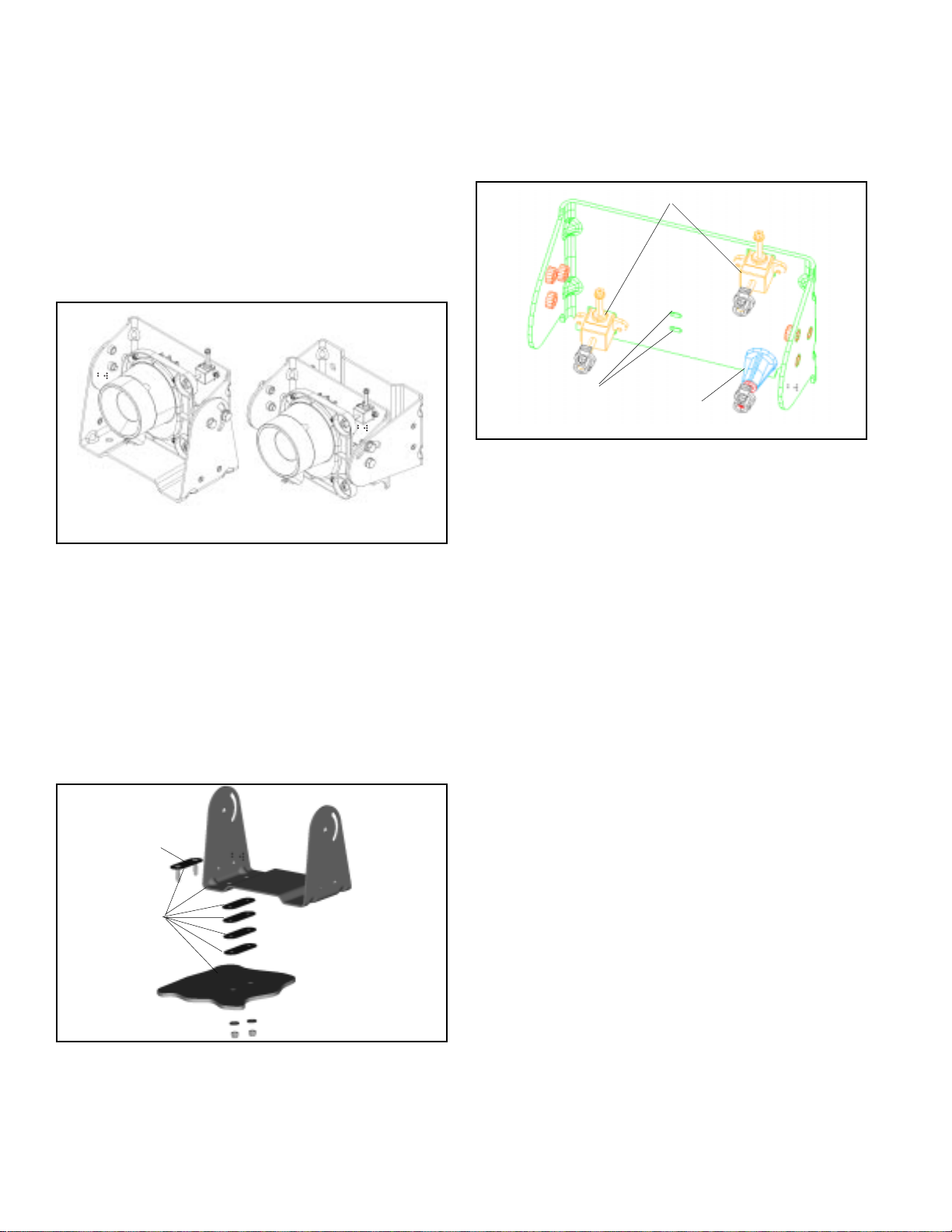
IR CAMERA BRACKET KIT (PIECE NO.
5010078) INCLUDES:
Mounting Bracket Kit (piece no. 5010187) – The mounting
bracket is designed to mount to the vehicle roof (horizontal
mounting) or faring area (vertical mounting) and needs to be
mounted parallel to the lateral axis of the vehicle (side to
side). A template is provided to help guide the drilling of
holes. Two stud plates with 1/4-20 studs mount the bracket
to the vehicle. The final torque on the studs should be
90-100 in-lbs.
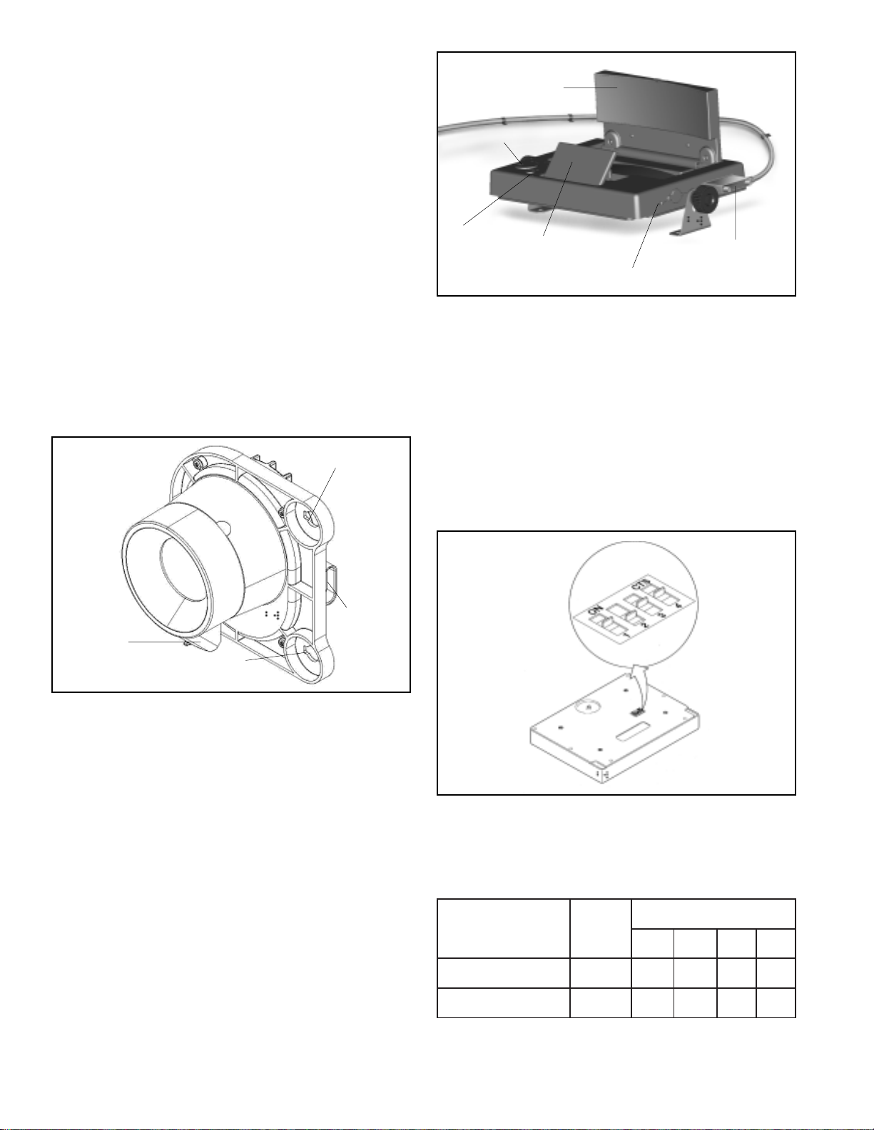
IR Camera Bracket with Aiming Adjusters (piece no.
5010673) – One IR camera bracket is provided in the IR
camera bracket kit. The bracket includes a standoff base,
standoff pivot assembly and aiming adjusters all of which
are preinstalled.
Aiming Adjuster Assemblies
Holes for Harness
Cable Tie
FIGURE 4 - IR CAMERA BRACKET WITH AIMING
ADJUSTERS
Standoff and
Pivot Assembly
Horizontal Mounted Bracket
(Roof Mount)
FIGURE 2 - MOUNTING BRACKET ORIENTATIONS
Vertical Mounted Bracket
(Faring Mount)
The mounting bracket kit also includes shims that should
be used to level the mounting bracket. A sealant is to be
used between the vehicle, mounting bracket, and stud plate.
Verify that the sealant has been applied appropriately,
according to the Installation Instructions. Additional
mounting hardware is also included in the kit.
Stud Plate
Apply sealant
between
these
surfaces
Add shims if
the surface is
not level
Roof
Cable Tie – A cable tie (to fasten the IR camera harness
to the IR camera bracket) is also included in the IR camera
bracket kit.
Hardware – The IR camera bracket kit includes all of the
necessary hardware to assemble the IR camera, IR camera
bracket, and mounting bracket.
CB STYLE MOUNTING KIT (PIECE NO.
5010081)
The CB style mounting kit contains the necessary mounting
hardware for the CB style dashboard option and CB style
overhead option. When the display is mounted, the combiner
surface (and virtual image) must be viewable in the driver’s
peripheral vision. A template is provided to help guide the
drilling of holes.
The CB style mounting kit includes the following items.
Mounting brackets (piece no. 5009616) – The CB style
mounting kit includes two mounting brackets that can be
used for either the CB dashboard mount or CB overhead
mount.
FIGURE 3 - MOUNTING BRACKET KIT CONTENTS
4
Page 5
Mounting Brackets
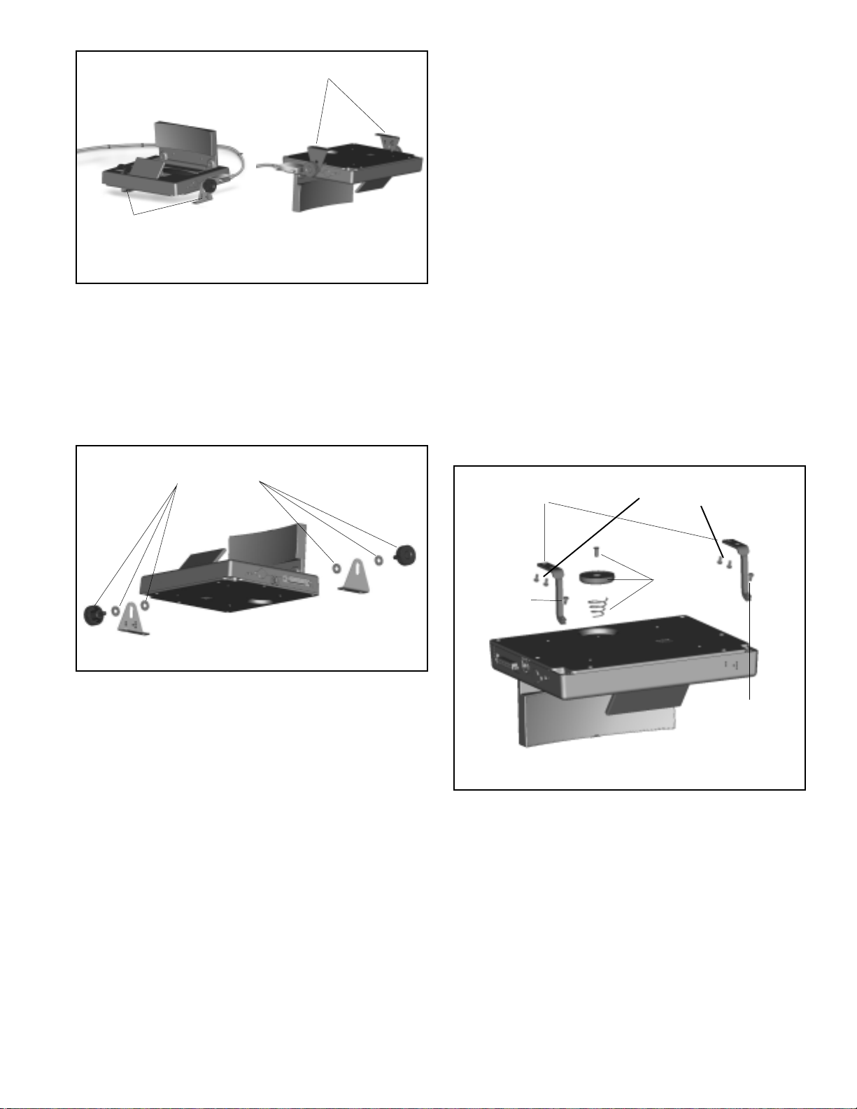
FRICTION HINGE MOUNTING KIT (PIECE NO.
5010082)
Mounting Brackets
CB Style (Dashboard)
FIGURE 5 - CB MOUNTING BRACKETS
CB Style (Overhead)
Knob kit (service piece no. 5010247) – The knob kit
includes four 1/4 in. flat washers and two 1/4-20 threaded
knobs, which are installed onto both sides of the display
when it is mounted in the CB style.
Knob Kit
Components
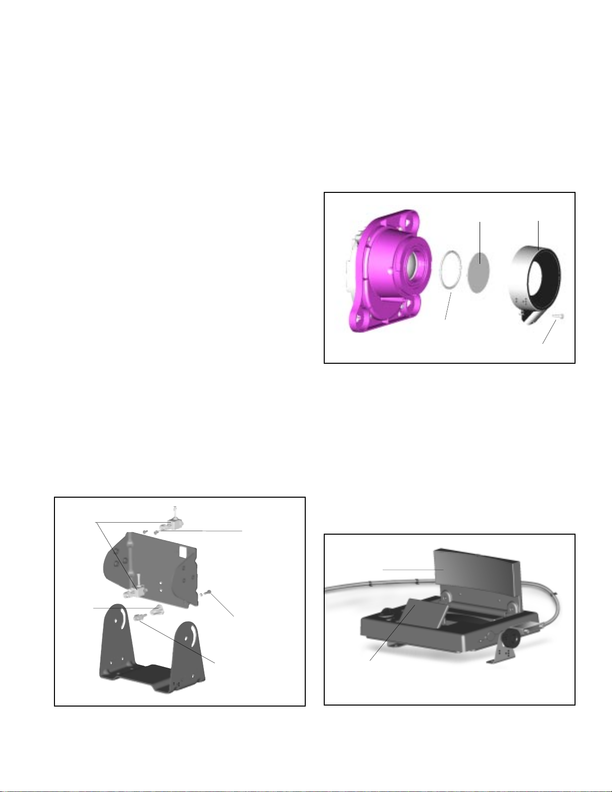
Friction hinge mounting allows the driver to use the sun
®
visor during the day and the XVision
system at night. The
display pivots on a pair of friction hinges, similar to a vehicle
sun visor. The hinges allow the display to be flipped out of
the way of the visor and latched into either position by use
of a magnet and striker plates.
The friction hinge mounting kit includes the following items.
Hinge Supports – Two hinge supports secure the display
to the vehicle headliner when the friction hinge mount is
used. The hinge supports are fastened to the headliner with
four #10 Plastite
®
pan head screws and to the display with
two M2.5 threadroll pan head screws.
Magnet Kit (piece no. 5010524) – The magnet kit includes
a magnet, striker plates, spring, and hardware. The magnet
and spring are attached to the display, and one (1) striker
plate is fastened to the vehicle headliner. The other striker
plates (2) sandwich the sun visor.
Hinge Supports
#10 Plastite Pan Head
Screws (Qty. 4)
FIGURE 6 - KNOB KIT COMPONENTS
Plastite® screws – The CB style mounting kit includes four
#10 Plastite® screws, each 1/2 in. long. Depending on the
chosen CB mount, the screws are used to attach the
mounting brackets to either the headliner or dashboard of
the vehicle.
Magnet Kit
M2.5
Threadroll
Pan Head
Screw
FIGURE 7 - FRICTION HINGE MOUNTING KIT
COMPONENTS
Components
M2.5
Threadroll
Pan Head
Screw
Screw and Shim Kit (piece no. 5010249) – The screw
and shim kit includes twelve #10 Plastite® pan head screws
and twelve spacer blocks. The screws are used to fasten
the friction hinge supports to the vehicle headliner and are
supplied in three different lengths. The spacer blocks can
be used to level the friction hinge supports, if necessary.
Based on the number of spacers needed to level out the
mount, use either the 1/2 in., 3/4 in., or 1 in. long screws.
5
Page 6
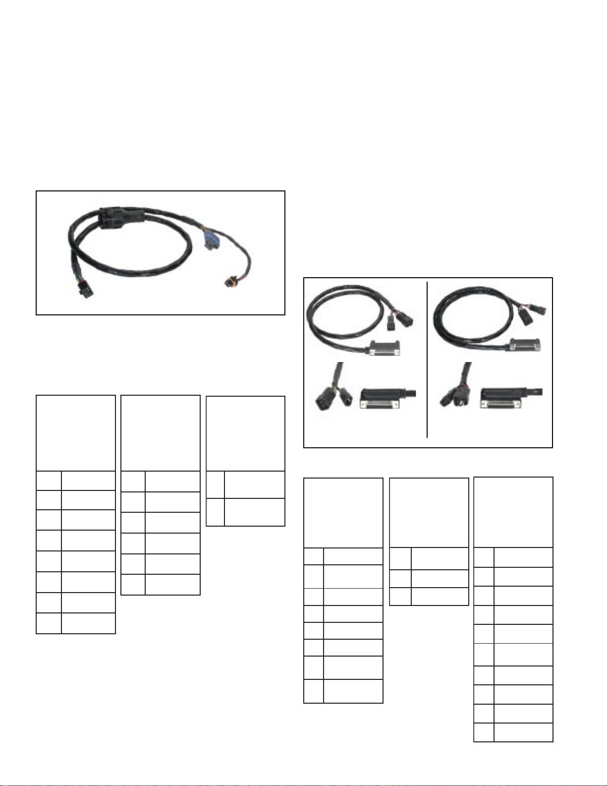
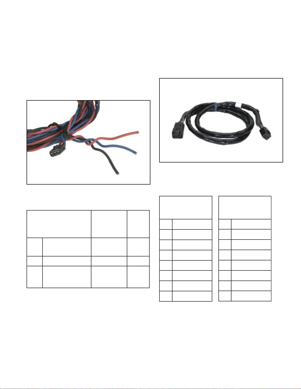
HARNESS KIT (PIECE NO. 5010083)
The harness kit includes:
IR Camera Harness (piece no. 5010246, service piece
no. 801156) – The IR camera harness is approximately three
feet long and has three connectors. The 8-pin connector
connects to the display harness, the 2-pin connector
connects to the IR camera window heater, and the 6-pin
connector connects to the IR camera power and video. See
Figure 8 and Table 1 below.
FIGURE 8 - IR CAMERA HARNESS
Display Harnesses (CB style: piece no. 5010259, service
piece no. 801151; Friction Hinge: piece no. 5010263,
service piece no. 801155) – The harness kit includes two
display harnesses, one for CB style mounts and one for the
friction hinge mounts. The harness for the CB style mounts
exits toward the back of the display, and the harness for the
friction hinge mount exits toward the front of the display.
Both harnesses are three feet long. When installed, the
display harness should be secured with a cable tie every
three inches.
Both display harnesses have three connectors. The 25-pin
connector connects to the display, the 3-pin
connector connects to the vehicle harness, and the
8-pin connector connects to the IR camera harness.
See Figure 9 and Table 2.
TABLE 1 - IR CAMERA HARNESS PIN OUTS
drakcaPihpleD
rotcennoC
stcatnoc6
rotcennoC
65826121N/P
lanimreT
57042121N/P
A+aremaCRI
B-aremaCRI
CwoLoediV
DhgiHoediV
EniarDoediV
FdesUtoN
G-retaeHwodniW
H+retaeHwodniW
drakcaPihpleD
rotcennoC
stcatnoc8
rotcennoC
68874021N/P
lanimreT
76774021N/P
A+aremaCRI
B-aremaCRI
CwoLoediV
DhgiHoediV
EgulP
FgulP
drakcaPihpleD
rotcennoC
stcatnoc2
rotcennoC
25826121N/P
lanimreT
57042121N/P
Display Harness
CB Mounts
FIGURE 9 - DISPLAY HARNESSES
Display Harness
Friction Hinge Mount
TABLE 2 - DISPLAY HARNESS PIN OUTS
A
B
wodniW
+retaeH
wodniW
-retaeH
A+aremaCRI
B
CwoLoediV
DhgiHoediV
EniarDoediV
FdesUtoN
G
H
drakcaPihpleD
rotcennoC
stcatnoc8
rotcennoC
88654021N/P
lanimreT
49895021N/P
A
aremaCRI
dnuorG
-
+
BdnuorGelciheV
CevitcApmaldaeH
retaeHwodniW
retaeHwodniW
drakcaPihpleD
rotcennoC
stcatnoc3
rotcennoC
28774021N/P
lanimreT
49895021N/P
.ngielciheV
V21+
2dnuorGelciheV
3woLoediV
4hgiHoediV
11evitcApmaldaeH
31V21+.ngielciheV
41
51-retaeHwodniW
61niarDoediV
erutainimbuSD
stcatnoC52
aremaCRI
dnuorG
42+retaeHwodniW
52+aremaCRI
6
Page 7
Vehicle Harness (piece no. 5010260, service piece no.
801157) – The vehicle harness is approximately 12 feet
®
long and provides power to the XVision
system. The harness
is made of a twisted tri-wire, which needs to be fused to the
vehicle ignition and headlamps. The harness has one 3-pin
connector that connects to the display harness.
The vehicle harness is not designed to be mounted externally.
After the harness is routed and secured with cable ties, the
excess wire should be removed and the fuse holders
installed. See Figure 10 and Table 3.
Jumper Harness (piece no. 5010441, service piece no.
801152) – The jumper harness acts as an “extension cord”
when the display and IR camera are mounted more than six
feet apart. The harness has two 8-pin connectors, one
connects directly to the IR camera harness and the other to
the display harness. The jumper harness is not designed to
be mounted externally. See Figure 11 and Table 4.
FIGURE 10 - VEHICLE HARNESS
TABLE 3 - VEHICLE HARNESS PIN OUTS
rotcennoCdrakcaPihpleD
stcatnoC3
28774021N/ProtcennoC
desuFroloC
49895021N/PlanimreT
A
noitingielciheV
stloV21+
nepowolsA3
).xam(esuf
DER
BdnuorgelciheVKCALB
nepotsafA1
CevitcapmaldaeH
esuf
EULB
).xam(
Harness Hardware – Two fuse holders, three butt splices,
a 1 A fast open fuse and a 3 A slow open fuse are all included
in the harness kit. Labels are also included and must be
applied to the fuse holders after installation.
FIGURE 11 - JUMPER HARNESS
TABLE 4 - JUMPER HARNESS PIN OUTS
stcatnoc8
A+aremaCRI
BdnuorGaremaCRI
CwoLoediV
DhgiHoediV
EniarDoediV
FdesUtoN
G-retaeHwodniW
H+retaeHwodniW
rotcennoCdrakcaPihpleD
88654021N/ProtcennoC
49895021N/PlanimreT
A+aremaCRI
B-aremaCRI
CwoLoediV
DhgiHoediV
EniarDoediV
FdesUtoN
G-retaeHwodniW
H+retaeHwodniW
stcatnoc8
rotcennoCdrakcaPihpleD
68874021N/ProtcennoC
76774021N/PlanimreT
7
Page 8
AIMING ADJUSTER TOOL
The aiming adjuster tool is included with the XVision® system
kit, but cannot be ordered individually. It is the only tool that
should be used to install the IR camera onto the
aiming adjusters.
IR CAMERA/ DISPLAY COMBINATION
The IR camera and display are serviceable and can be
ordered individually. The IR camera/display combination can
be purchased as an entire XVision
IR Camera (piece no. 5008214, service piece no. 801150)
The IR camera must always be mounted externally to the
vehicle and attaches to the standoff pivot assembly and
aiming adjusters on the IR camera bracket. The IR camera
is operational within the range of -40°C to 60°C.
The IR camera has two electrical connections: a 6-pin
IR camera connector and a 2-pin window heater connector.
®
system.
Aiming
Adjuster
Mounting
Combiner
Intensity
Control
On/Off
Switch
FIGURE 13 - DISPLAY (SHOWN IN CB STYLE MOUNT
(DASHBOARD) POSITION WITH DISPLAY HARNESS)
Fold Mirror
Video In/Out
25-pin Connector
Switch
The orientation of the virtual image on the display will depend
on the display mounting style that you have chosen. On the
bottom of the display, under a switch cover, there are four
dual inline position (DIP) switches which allow you to rotate
or invert the image. To access the DIP switches, slide the
cover away from the 25-pin connector. Displays arrive from
the factory with the DIP switches configured for the CB style
dashboard mount. Refer to Table 5 for the DIP switch settings
appropriate for your mount.
Window
Heater
Connection
FIGURE 12 - IR CAMERA
Standoff Pivot
Mounting
IR Camera
Connection
Video Display (piece no. 5010210, service piece no.
801154) – The display is operational within the range of
-40°C to 60°C. During power-up, the Bendix® icon will be
displayed in the combiner for approximately 45 seconds.
The intensity control will need to be adjusted according to
light conditions and driver preference. After the initial
warm-up, the IR camera’s field of view (FOV) will be displayed
in the combiner.
FIGURE 14 - DISPLAY DIP SWITCHES FOR DASHBOARD
MOUNT
TABLE 5 - DIP SWITCH POSITIONS
noitisoPgnitnuoM
oediV
tamroF
1234
snoitisoPhctiwSPID
detnuoMhsaD)CSTN(A/NFFONONO
detnuoMdaehrevO)CSTN(A/NFFOFFOFFO
8
Page 9
REPLACEMENT KITS
The following five kits contain replacement parts for the
XVision® System. Each of the replacement kits can be
ordered through Bendix.
For instructions on installing replacement parts, see the
appropriate section of Servicing the XVision® System,
beginning on Page 10.
AIMING ADJUSTER REPLACEMENT KIT
(PIECE NO. 5010079)
The IR camera bracket can only be ordered as a component
of the IR camera bracket kit. However, the components that
attach to the IR camera bracket to aim and adjust the
IR camera can each be ordered in the aiming adjuster
replacement kit . The kit includes the items below.
standoff pivot assembly (QTY 1) – fastens to the IR camera
standoff base with a maximum torque of 16 in-lbs.
standoff base (QTY 1) – fastens to the IR camera bracket
with #10 Plastite® Hex® flange head screw and lockwasher
with a maximum torque of 18-20 in-lbs.
aiming adjusters (QTY 2) – latch the IR camera into position
on the IR camera bracket and allow the IR camera forward
Field of Vision (FOV) to be adjusted horizontally and/or
vertically. The adjustment screw head(s) accommodate an
E8 external Torx® or a T15 internal Torx® tool. (The aiming
adjusters are fastened to the IR camera bracket and torqued
to 18 in-lbs. with four #8-32 Hex®/Torx® screws.)
WINDOW REPLACEMENT KIT (PIECE NO.
5010192)
The window replacement kit includes one replacement IR
camera window, o-ring and locking pin. See Figure 16.
HEATER REPLACEMENT KIT (PIECE NO.
5010193)
The heater replacement kit includes one replacement
IR camera heater and locking pin. See Figure 16.
Camera
Window
O-ring
IR Camera
FIGURE 16 - IR CAMERA AND CAMERA HEATER
Camera
Heater
Locking Pin
COMBINER MIRROR REPLACEMENT KIT
(PIECE NO. 5010190)
The combiner mirror replacement kit includes one
replacement combiner. See Figures 17 & 28.
Aiming
Adjusters
Standoff
Base
FIGURE 15 - AIMING ADJUSTER REPLACEMENT KIT
#8-32
Hex®/ Torx
(18 in-lbs.)
#10 Plastite® Hex
flange with lock
washer
(18-20 in-lbs.)
Standoff Pivot
Assembly
(16 in-lbs.)
FOLD MIRROR REPLACEMENT KIT (PIECE
NO. 5010189)
The fold mirror replacement kit contains one replacement
fold mirror. See Figures 17 & 29.
®
Combiner
®
Fold Mirror
FIGURE 17 - COMBINER AND FOLD MIRROR
9
Page 10

ELECTRICAL SYSTEM
OPERATING INPUT VOLTAGE
POWER AND GROUND (POWER INPUTS)
Electrical power to the XVision® system is provided through
the vehicle harness. The vehicle ignition wire {(A) Red} should
be fused to a 3 A slow open fuse (maximum) and connected
to the ignition bus of the vehicle. The ground wire {(B) black}
should be connected to the ground bus of the vehicle. The
headlamp active wire {(C) blue} should be fused to a 1 A fast
open fuse (maximum) and connected to the vehicle headlamp
circuit. When the headlamps are on, 12 V should be present
on the blue wire.
WARNING: Vehicle power and headlight circuits MUST
be fused. Permanent damage to the display, IR
camera, or vehicle electrical system could occur if
power to these units is not fused. Eliminating fuses
from circuit will void all warranties.
IMPORTANT: When replacing a fuse, it is important
to use only the specified fuse with the correct
amperage, as listed above. The use of a fuse with a
rating other than indicated may result in a dangerous
electrical system overload. Repeated opening of a
properly rated fuse indicates a problem in the circuit
that must be corrected.
The IR camera is operational in the temperature range
between -40°C to 60°C. Normally, the IR camera takes about
45 seconds to warm up. However, as the external
temperature gets closer to the extremes listed, the warmup time will begin to approach two minutes. Refer to Figure
19.
2
1
Time (minutes)
-40
040
60
Temperature (Celsius)
FIGURE 19 - OPERATIONAL TEMPERATURE RANGE AND
WARM-UP TIME OF IR CAMERA
3 AMP slow
open fuse
bus
Ground
Bus
Ignition
Switch
1 AMP fast
open fuse
Headlamp
Butt
Splice
Headlamp
Switch
Battery
Red
A
Wire
Blue
C
Wire
Black
B
Wire
Ignition
FIGURE 18 - XVISION® SYSTEM ELECTRICAL SCHEMATIC
The IR camera and display are compatible with 12 V DC
battery systems with a chassis ground.
SERVICING THE XVISION® SYSTEM
The following sections provide instructions for maintaining
and/or replacing components of the XVision® system.
CAMERA MOUNTING BRACKET REPLACEMENT
1. Loosen and remove the four 5/16 in. bolts securing the
IR camera bracket to the mounting bracket.
2. Disconnect the camera harnesses (2-pin and 6-pin).
Remove the IR camera assembly.
3. From inside the cab, remove all mounting hardware from
the mounting bracket.
4. Remove the stud plates, mounting bracket, and shims
(if used).
5. Clean the area around the drilled holes in the cab.
6. Align the new mounting bracket with the holes in the
cab. Note: use new mounting hardware for the
installation.
10
Page 11

Mounting bracket can be
Driver’s
Centerline
of Sight
Lateral
Axis of
Vehicle
FIGURE 20 - MOUNTING BRACKET AND LATERAL AXIS OF
VEHICLE
anywhere along driver’s
centerline of sight and
must be parallel to lateral
axis of vehicle
7. Verify that the mounting bracket is level. If it is not, use
the shims included in the mounting bracket kit.
8. Apply sealant between all contact areas (between the
roof and the shims, between each shim, between the
shims and the bracket, and between the bracket and
stud plates).
9. Install the stud plates on both sides of the replacement
mounting bracket.
10. From inside the cab, tighten all mounting hardware to
90-100 in-lbs.
11. Insert the four 5/16 in. bolts through the mounting
bracket into the new IR camera bracket and hand
tighten. Allow enough mobility for adjustments to be
made during the aiming procedure.
12. Reconnect the 2-pin and 6-pin harnesses.
13. Aim and adjust the IR camera. Refer to Aiming the IR
Camera on Pages 21-22.
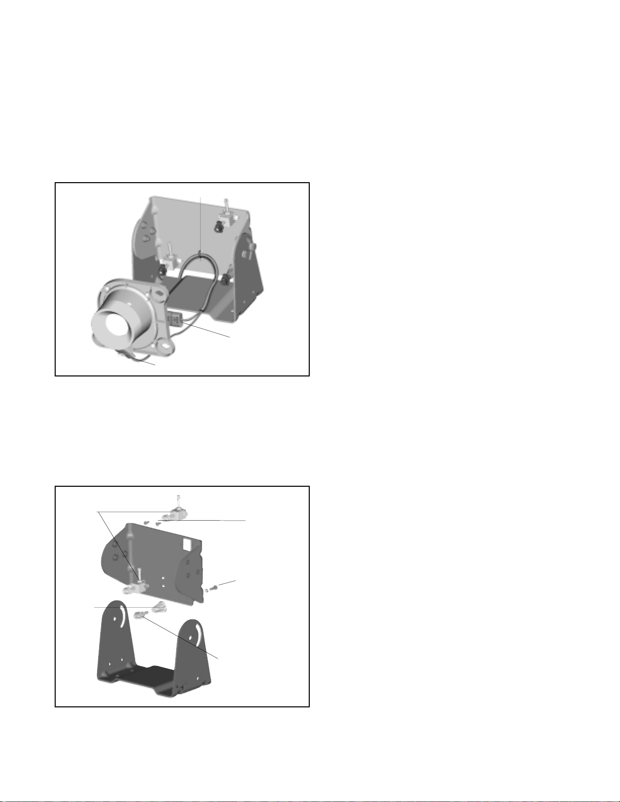
IR CAMERA BRACKET REPLACEMENT
The new IR camera bracket will have factory-installed aiming
adjusters and standoff base/pivot assembly.
1. Remove the camera shroud, if equipped. Unlock the IR
camera by turning the two IR camera
aiming adjusters and the IR camera standoff
1/4 turn counterclockwise using the adjuster tool.
2. Disconnect the IR camera connector (6-pin) and the
window heater connector (2-pin) of the IR camera
harness.
3. Remove the IR camera and IR camera harness from
the IR camera bracket. The IR camera harness should
be tied to the bracket with a cable tie. Cut the tie to
remove the harness.
4. Loosen and remove the four 5/16 in. bolts from the IR
camera bracket.
5. Remove the old IR camera bracket.
6. Place the new IR camera bracket in the same location
as the old.
7. Insert the four 5/16 in. bolts through the mounting
bracket and new IR camera bracket into the threaded
inserts, and hand-tighten.
8. Replace the camera shroud.
Attach the IR camera harness
9. Pull the IR camera harness through the opening between
the IR camera bracket and mounting bracket.
10. Plug the 2-pin connector of the IR camera harness into
the window heater. Refer to Figure 21.
11. Plug the 6-pin connector of the IR camera harness into
the IR camera connection. Refer to Figure 21.
12. Loosely install the harness cable tie around the harness.
Cable Tie
6-pin connector
2-pin connector
FIGURE 21 - CONNECTING THE CAMERA HARNESSES
11
Page 12

Attach the IR camera to the IR camera bracket
13. Position the IR camera onto the factory-installed aiming
assemblies. Refer to Figure 22.
14. Rotate the pivot locks on the ends of the aiming
assemblies 1/4 turn clockwise, using the included
aiming adjuster tool. This will lock the IR camera in
position.
15. Adjust the harness, ensuring that it is not pulled tight,
which could cause a water leak into the camera.
Securely tighten the harness cable tie to prevent wire
chaffing from the bracket.
16. Aim and adjust the IR camera. Refer to Aiming the IR
Camera on pages 21 and 22.
Aiming Assembly
IR CAMERA
Maintaining
The IR camera weighs approximately 2 lbs. Conduct the
following maintenance inspections on a regular basis.
1. Inspect the harnessing for chafing.
2. Inspect mounting for loose bolts.
3. Inspect aiming adjusters for cracks or breaks. Replace
as necessary.
4. Inspect and clean the camera window.
Replacing IR Camera
1. Unlock the IR camera by turning the two IR camera
aiming adjusters and the IR camera standoff
1/4 turn counterclockwise.
2. Remove the IR camera from the IR camera bracket to
get easier access to the connectors.
3. Disconnect the 6-pin IR camera connector and the 2-pin
window heater connector of the IR camera harness from
the IR camera.
4. Install new camera. Plug the 2-pin connector of the IR
camera harness into the window heater. Refer to Figure
23.
FIGURE 22 - FULLY ASSEMBLED IR CAMERA
Cable Tie
6-pin connector
2-pin connector
FIGURE 23 - CONNECTING THE IR CAMERA HARNESSES
5. Plug the 6-pin connector of the IR camera harness into
the IR camera connection. Refer to Figure 23.
6. Position the IR camera onto the factory-installed
aiming adjusters.
7. Rotate the pivot locks (on the ends of the aiming
adjusters) 1/4 turn clockwise, using the included aiming
adjuster tool. This will lock the IR camera in position.
12
Page 13
Replacing the Aiming Adjusters
1. Unlock the IR camera by turning the two IR camera
aiming adjusters and the IR camera standoff
1/4 turn counterclockwise.
2. Remove the IR camera from the IR camera bracket to
get easier access to the connectors.
3. Disconnect the 6-pin IR camera connector and the 2-pin
window heater connector of the IR camera harness from
the IR camera. Cut the cable tie to allow access. Refer
to Figure 24.
Cable Tie
6-pin connector
2-pin connector
FIGURE 24 - CONNECTING THE CAMERA HARNESSES
4. Remove the #8-32 Hex®/Torx® screws from the damaged
aiming adjuster(s). Refer to Figure 25.
5. Remove the Plastite® Hex® flange head screw and #10
lock washer from the damaged standoff pivot assembly.
6. Replace the damaged parts with the new aiming adjusters
and standoff pivot assembly that were received with the
service kit (piece no. 5010079).
NOTE: The IR camera bracket can only be ordered
as a component of the IR camera bracket kit. However,
the components that attach to the IR camera bracket
to aim and adjust the IR camera can each be ordered
in the aiming adjuster replacement kit. The kit includes
the items below.
standoff pivot assembly (QTY 1) – fastens to the IR
camera standoff base with a maximum torque of
16 in-lbs.
standoff base (QTY 1) – fastens to the IR camera
®
bracket with #10 Plastite
Hex® flange head screw
and lockwasher with a maximum torque of
18-20 in-lbs.
aiming adjusters (QTY 2) – latch the IR camera into
position on the IR camera bracket and allow the IR
camera forward FOV to be adjusted horizontally and/
or vertically. The adjustment screw head(s)
accommodate an E8 external Torx
®
or a T15 internal
Torx® tool. (The aiming adjusters are fastened to the
IR camera bracket and torqued to 18 in-lbs. with four
#8-32 Hex®/Torx® screws.
7. Install the new aiming adjuster(s) using the #8-32
Hex®/Torx® screws. Torque the screws to 18 in-lbs.
8. Install the new standoff pivot assembly using the #10
lock washer and Plastite® Hex® flange head screw.
Torque the screw to 16 in-lbs.
Aiming
Adjusters
Standoff
Base
FIGURE 25 - AIMING ADJUSTER REPLACEMENT
KIT COMPONENTS
#8-32
Hex®/ Torx
(18 in-lbs.)
#10 Plastite® Hex
flange with lock
washer
(18-20 in-lbs.)
Standoff Pivot
Assembly
(16 in-lbs.)
®
®
13
Page 14

IR CAMERA WINDOW
Maintaining
The IR camera window, a 1.3 mm thick silicon disk, is an
optical element and should be cleaned when it becomes
dirty or filled with debris. Dirt and debris can affect the
IR camera performance.
To clean the window, use a soft, damp cloth moistened with
window cleaning solution. Shop rags and paper towels will
scratch optical surfaces.
NOTE: The IR camera heater cannot melt large
amounts of packed snow in the window area. It is
recommended that the snow be removed manually
prior to system operation. When cleaning ice or snow
from the IR camera, use a commercially available spray
deicer; do not use scrapers or sharp instruments that
may scratch or break the window.
Replacing
If the window cracks or breaks, it must be replaced.
8. Turn the bezel heater assembly 1/4 turn clockwise to
reattach it to the IR camera. Note: Ensure the window
is positioned correctly or it can be damaged when
installing the bezel.
9. Lock the bezel heater assembly in place with the bezel
retention plug.
10. Plug the 2-pin connector of the IR camera harness into
the window heater. Refer to Figure 24 on page 12.
11. Plug the 6-pin connector of the IR camera harness into
the IR camera connection. Refer to Figure 24 on
page 12.
12. Position the IR camera onto the factory-installed
aiming assemblies.
13. Rotate the pivot locks on the end of the aiming
assemblies 1/4 turn clockwise, using the aiming
adjuster tool. This will lock the IR camera in position.
14. Aim and adjust the IR camera. Refer to Aiming the IR
Camera on pages 21 and 22.
1. Unlock the IR camera assembly by turning the two IR
camera aiming adjusters and the standoff pivot
assembly 1/4 turn counterclockwise.
2. Remove the IR camera from the IR camera bracket to
gain easier access to the connectors.
3. Disconnect the 6-pin IR camera connector and the
2-pin window heater connection of the IR camera
harness from the IR camera.
4. Lay the IR camera face-up for easy access to the bezel
retaining plug. Refer to Figure 26.
5. Remove the bezel retaining plug.
6. Turn the bezel heater assembly 1/4 turn
counterclockwise, until it separates from the IR camera.
7. Replace the damaged window and seal.
NOTE: The replacement window is treated with a black
scratch-resistant coating on one side only. The side
that appears black must face the environment.
NOTE: If the area between the IR camera window
and IR camera lens is contaminated because of a
damaged seal or window, carefully remove the
contamination. If a window cleaning solvent is used
to clean the area, be sure to remove all of the moisture
from the sealed cavity before assembling the o-ring
seal and window. Moisture remaining in the sealed
area will affect the performance of the IR camera.
NOTE: Use care when removing shards of glass.
IR Camera
Window
Black side
IR Camera
FIGURE 26 - IR CAMERA WINDOW AND BEZEL
RETAINING PLUG
IR Camera
Window Seal
Bezel Heater
Retaining
Assembly
Bezel
Plug
14
Page 15

IR CAMERA WINDOW HEATER REPLACEMENT
1. Unlock the IR camera by turning the two IR camera
aiming adjusters and the IR camera standoff 1/4
turn counterclockwise.
2. Remove the IR camera from the IR camera bracket to
gain easier access to the connectors.
3. Disconnect the 6-pin IR camera connector and the
2-pin window heater connector of the IR camera harness
from the IR camera.
4. Lay the IR camera face-up for easier access to the
bezel retaining plug. Refer to Figure 27.
Bezel Heater
Assembly
IR Camera
Window
Black side
IR Camera
IR Camera
FIGURE 27 - BEZEL HEATER ASSEMBLY AND
RETAINING PLUG
Window Seal
Retaining Plug
Bezel
5. Remove the bezel retaining plug.
6. Turn the bezel heater assembly 1/4 turn
counterclockwise, until it separates from the IR camera.
Use care to prevent the window from falling and breaking.
7. Turn the new bezel heater assembly 1/4 turn clockwise
onto the IR camera. Note: Ensure the window has not
moved or it will be damaged.
8. Lock the new heater in position with the bezel
retaining plug.
9. Plug the 2-pin connector of the IR camera harness into
the window heater. Refer to Figure 24.
10. Plug the 6-pin connector of the IR camera harness into
the IR camera connection. Refer to Figure 24.
11. Position the IR camera onto the factory-installed
aiming assemblies.
12. Rotate the pivot locks on the end of the aiming
assemblies 1/4 turn clockwise, using the aiming
adjuster tool. This will lock the IR camera in position.
13. Aim and adjust the IR camera. Refer to Aiming the IR
Camera on pages 21 and 22.
15
Page 16

DISPLAY
Maintaining the Fold Mirror
Maintaining the Combiner Mirror
The combiner is a sensitive optical element and should be
cleaned when it becomes dirty or filled with debris. Dirt and
debris can affect the display performance.
1. Remove heavy dirt or grit with air.
2. Clean the combiner with a soft, damp cloth moistened
with window cleaning solution. Shop rags and paper
towels will scratch this optical surface.
NOTE: Do not use ammonia to clean any of the
display components. It will remove scratch-resistant
and anti-glare coatings.
Replacing the Combiner Mirror
1. Locate the depression in the center of the combiner door.
Refer to Figure 28.
Remove heavy dirt or grit from the fold mirror with air. Clean
the fold mirror with a soft, damp cloth moistened with window
cleaning solution. Shop rags and paper towels will scratch
this optical surface.
NOTE: Do not use ammonia to clean any of the display
components. It will remove scratch-resistant and
anti-glare coatings.
Replacing the Fold Mirror
1. Locate one of the four depressions along the perimeter
of the fold mirror. Refer to Figure 29.
Depression in
Combiner Door
FIGURE 28 - REPLACEMENT COMBINER
Combiner
Mirror
2. Pry the old combiner out by inserting a small
screwdriver or pocket knife into the depressions and
pushing upward.
3. Snap the new combiner gently in place.
Depressions
in Fold Mirror
FIGURE 29 - REPLACEMENT FOLD MIRROR
2. Pry the old fold mirror out by inserting a small
screwdriver or pocket knife into one of the depressions
and pushing upward.
3. Snap the new fold mirror gently into place.
16
Page 17

Display Bracket Replacement - CB Style Mount
(Dashboard)
1. Unscrew and disconnect the 25-pin connector of the
display harness.
2. Unscrew the threaded knobs from the display and
brackets. Set the display, knobs, and washers aside.
Exercise care to prevent dropping the washers into the
venting on the dash.
®
3. Remove the four #10 Plastite
pan head screws from the
brackets and dashboard. Set the four screws aside.
4. Secure the replacement brackets with the four
screws
from Step 3.
5. Torque the screws to approximately 20 in-lbs.
6. Slide one of the washers onto one of the threaded knobs.
7. Hold one washer between the display and a bracket while
threading the washer/knob from the outside of the
bracket. See Figure 30.
Display Bracket Replacement - CB Style Mount
(Overhead)
Refer to CB Style Mount (Dashboard) procedure.
Display Bracket Replacement - Friction Hinge
Mount (Visor)
1. Unscrew and disconnect the 25-pin connector of the
display harness.
2. Flip the display down to allow access to the friction
hinge supports.
3. Remove the four #10 Plastite® pan head screws that
secure the display to the headliner.
4. Remove the two M2.5 threadroll pan head screws that
secure the friction hinge supports to the display.
5. Secure the new friction hinge supports to the display
with the M2.5 threadroll pan head screws.
IMPORTANT: Do not exceed 15 in-lbs. when
fastening. If 15 in-lbs. are exceeded, the screw head
will shear off or the stand-offs will strip. The threadroll
screws will form threads in the standoffs as they are
tightened. If it feels as though the screw is binding,
back out the screw slightly and continue to tighten to
prevent breakage.
6. Secure the new friction hinge supports to the headliner
with the four #10 Plastite® pan head screws. Torque the
screws to approximately 15 in-lbs.
7. Reconnect the 25-pin connector of the display harness.
FIGURE 30 - WASHERS AND THREADED KNOBS [SHOWN
IN CB STYLE MOUNT (OVERHEAD) POSITION]
8. Repeat steps 6 and 7 for the other side of the display.
9. Reconnect the 25-pin connector of the display harness.
Base Plate 8-32 Mounting
Four 8-32 inserts are provided in the display base.
A template is provided to help guide the drilling
of holes. Use a 13/64 in. bit for drilling the four clearance
holes. Typically, this installation is used when the display
is being recessed.
17
Page 18

Display Replacement
IMPORTANT: The display is not waterproof and should
not be exposed to rain, snow, or moisture. Under
extreme conditions, water may enter the circuitry
through the panel buttons. In general, treat the display
as you would a pocket calculator or other small non waterproof electronic instrument.
IMPORTANT: The XVision® system display
technology is designed to meet severe temperature
extremes. However, when installing the display for
head-down operation or for use in extremely warm
climates, take necessary precautions to shield the
unit from direct sunlight. Prolonged exposure to direct
sunlight in enclosed truck cabs can damage the
system.
CB Style Mount (Dashboard and/or Overhead)
1. Unscrew and disconnect the 25-pin connector of the
display harness.
2. Unscrew the threaded knobs from the display and
brackets. Refer to Figure 30. Set the knobs and
washers aside.
3. Remove the old display.
4. Set the DIP switches on the new display according to
Table 5 on Page 7.
5. Slide one of the washers onto one of the threaded knobs.
6. Hold one washer between the new display and a bracket
while threading the washer/knob from the outside of the
bracket. Refer to Figure 30 on Page 15.
7. Repeat steps 5 and 6 for the other side of the display.
8. Plug the 25-pin connector of the display harness into
the new display.
Friction Hinge Mount (Visor)
1. Disconnect the 25-pin connector of the display harness.
2. Flip the display down to allow access to the friction
hinge supports.
3. Remove the four #10 Plastite® pan head screws that
secure the display to the headliner.
4. Remove the old display.
5. Remove the two M2.5 threadroll pan head screws that
secure the friction hinge supports to the display.
6. Secure the friction hinge supports to the new display
with the two M2.5 threadroll pan head screws.
IMPORTANT: Do not exceed 15 in-lbs. when
fastening. If 15 in-lbs. are exceeded, the screw head
will shear off or the stand-offs will strip. The threadroll
screws will form the threads on the standoffs as they
are tightened. If it feels as though the screw is binding,
back out the screw slightly and continue to tighten to
prevent breakage.
7. Secure the friction hinge supports to the headliner with
the four #10 Plastite® pan head screws.
8. Torque the screws to approximately 15 in-lbs.
9. Connect the 25-pin connector of the display harness to
the new display.
HARNESS REPLACEMENT
Each of the XVision® System harnesses is replaceable and
can be ordered through Bendix. Refer to Figure 43 on page
22 for more detailed information regarding the electrical wiring
of the system.
IR camera Harness
1. Remove the trim pieces covering the harness and the
cab headliner in areas covering the IR camera harness.
2. Disconnect the 8-pin connector of the IR camera
harness from the display harness.
3. Turn the two IR camera aiming adjusters and the IR
camera standoff pivot assembly 1/4 turn.
4. Remove the IR camera from the IR camera bracket to
gain easier access to the connectors.
5. Disconnect the IR camera connector (6-pin) and the
window heater connector (2-pin) of the IR camera
harness.
6. Cut the cable tie that secures the IR camera harness
to the IR camera mounting bracket.
7. From inside the cab, remove the externally threaded
nut from the harness.
8. Remove the IR camera harness from the cab.
9. Remove the externally threaded nut from the heat
shrinkable shroud assembly on the replacement
harness.
18
Page 19

10. From inside the cab, push the threaded nut through the
hole in the roof.
NOTE: The threaded section of the nut should protrude
past the vehicle surface. Refer to Figure 31.
Heat Shrinkable Shroud
Cable Tie
6-pin connector
O-Ring
Externally
Threaded Nut
3 in.
(Approximately)
FIGURE 31 - HEAT SHRINKABLE SHROUD ASSEMBLY
11. Place the o-ring over the externally threaded end.
12. Thread the harness through the externally threaded nut.
13. Fasten the heat shrinkable shroud onto the nut.
14. Hand-tighten the shroud from the outside of the roof.
15. Torque the heat-shrinkable shroud with a spanner wrench
to approximately 15 to 20 in-lbs. or until the o-ring is
slightly flattened.
16. Route the IR camera harness to the "A" pillar of the
cab.
17. Connect the 8-pin connector of the IR camera harness
to the display harness.
18. Pull the IR camera harness through the opening between
the IR camera bracket and mounting bracket.
19. Plug the 2-pin connector of the IR camera harness into
the window heater. Refer to Figure 32.
20. Plug the 6-pin connector of the IR camera harness into
the IR camera connection. Refer to Figure 32.
21. Loosely install the harness tie-wrap around the harness.
2-pin connector
FIGURE 32 - CONNECTING THE CAMERA HARNESSES
22. Position the IR camera onto the factory-installed aiming
assemblies. Refer to Figure 33.
23. Rotate the pivot locks on the ends of the aiming
assemblies 1/4 turn clockwise using the included aiming
adjuster tool. This will lock the IR camera in position.
FIGURE 33 - FULLY ASSEMBLED CAMERA
24. Securely tighten the harness cable tie.
25. Ensure that the harness reaches the "A" pillar without
trouble. Once the shroud assembly is heat-shrunk, the
harness cannot be moved or adjusted.
26. After the IR camera harness is properly secured and
routed, heat-shrink the shroud assembly from the
outside of the vehicle, using a heat gun.
WARNING: Do not touch the shroud assembly after
it has been heat-shrunk. It will be hot and may
cause burns.
IMPORTANT: Be careful not to melt the wiring or
o-ring during the heat shrinking process.
19
Page 20

27. Re-install the headliner and the “A” pillar cover.
28. Turn on the system to verify that it is operating correctly.
29. Aim and adjust the IR camera. Refer to Aiming the IR
Camera on pages 20 and 21.
Display Harness
1. Unscrew and disconnect the 25-pin connector of the
display harness.
2. Remove the trim pieces covering the harness.
3. Disconnect the display harness from the 8-pin
IR camera harness connector and the 3-pin vehicle
harness connector.
4. Remove any fasteners securing the display harness.
5. Connect the new display harness as follows:
• the 3-pin connector to the vehicle harness.
• the 8-pin connector to the IR camera harness.
• the 25-pin connector to the display.
6. Turn on the system to verify that it is operating correctly.
7. Replace the “A” pillar cover.
8. Secure the new display harness every 3 in. with
cable ties.
TABLE 6 - VEHICLE HARNESS WIRING
rotcennoCssenraHelciheV
stcatnoC3
A
noitingielciheV
stloV21+
desuFroloC
BdnuorgelciheVKCALB
CevitcapmaldaeH
3 AMP slow
open fuse
bus
Ground
Bus
Ignition
Switch
1 AMP fast
open fuse
Headlamp
Butt
Splice
Headlamp
Switch
Red
A
Wire
Blue
C
Wire
Black
B
Wire
Ignition
nepowolsA3
).xam(esuf
nepotsafA1
).xam(esuf
DER
EULB
Battery
Vehicle Harness
WARNING: Improper installation of the vehicle harness
can cause damage to your vehicle’s wiring and/or to
the XVision® system. It is the responsibility of the
installer to review wiring and service information for
the vehicle and to identify proper locations for
connecting the vehicle harness to the power. Many
modern vehicles have additional, built-in fused
accessory power breakouts and these breakouts
should be used if at all possible.
1. Remove the trim pieces covering the harness.
2. Disconnect the vehicle harness from the display
harness.
3. Remove the red wire (A-contact) from the ignition bus.
4. Remove the blue wire (C-contact) that is butt-spliced
between the headlamp and the headlamp switch.
5. Remove the black wire (ground) from the ground bus.
6. Remove any fasteners securing the vehicle harness.
7. Remove the old vehicle harness.
8. Strip the three ends of the new vehicle harness.
FIGURE 34 - XVISION® SYSTEM ELECTRICAL POWER
SCHEMATIC
9. Connect the red wire (A-contact) of the new vehicle
harness to the ignition bus with a 3 A slow open fuse.
10. Butt splice the blue wire (C-contact) of the new vehicle
harness between the headlamp and the headlamp
switch with a 1 A fast open fuse.
11. Connect the black wire to the ground bus.
12. Route the new vehicle harness to the display harness
and connect them.
13. Turn the system on to verify that it is operating correctly.
14. Secure the new vehicle harness every 6-12 in. with cable
ties.
15. Replace the “A” pillar cover.
Jumper Harness
1. Remove any fasteners securing the jumper harness.
2. Disconnect the jumper harness from the IR camera
harness and the display harness.
3. Connect the replacement jumper harness to the IR
camera harness and the display harness.
4. Turn the system on to verify that it is operating correctly.
5. Secure the new jumper harness every 6-12 in. with
cable ties.
20
Page 21

AIMING THE IR CAMERA
The aiming adjusters on the IR camera bracket allow the
forward field of view (FOV) of the IR camera to be adjusted
horizontally and vertically. The adjustment screw head(s)
will accommodate an E8 external Torx® or a T15 internal
Torx®.
When the IR camera is mounted, adjust the horizontal and
vertical aiming adjusters to align the IR camera FOV with
the display. The position of the virtual image on the display
and how the virtual image correlates to objects in the road
depends directly on IR camera aiming.
NOTE: Use two people to aim and adjust the IR
camera. One technician should view the virtual image
on the display while the other technician aims the IR
camera.
NOTE: Verify that the vehicle is level and that the
tires are properly inflated before beginning the IR
camera aiming procedure.
HORIZONTAL AIMING AND ADJUSTING
When the IR camera is not mounted directly above the driver,
the angle of the IR camera will need to be adjusted. Align
the display image horizontally with the objects in the road
to give the driver a sense of object location.
Combiner Image
Driver’s View
FIGURE 36 - IR CAMERA AIMED TOO FAR LEFT
Combiner image
1. Using Figures 35-38 and a T15 Torx wrench, adjust the
angle of the IR camera as needed.
NOTE: Two and one-quarter turns of the horizontal
adjuster is equal to one degree of IR camera
movement.
Horizontal
Aiming
Adjuster
FIGURE 35 - HORIZONTAL AIMING ADJUSTER
NOTE: Do not tamper with or adjust any
factory-installed screws while aiming the camera. Only
turn the horizontal aiming adjuster.
Driver’s View
FIGURE 37 - IR CAMERA AIMED TOO FAR RIGHT
Combiner image
Driver’s View
FIGURE 38 - IR CAMERA AIMED CORRECTLY
21
Page 22

VERTICAL AIMING AND ADJUSTING
The virtual image should be aligned vertically so that the
horizon appears in the lower one-half to one-third of the
combiner. Keeping the image at this adjustment should
provide a view of the road when the vehicle is driven up and
down hills.
The vertical aiming adjusters can accommodate
approximately ±4 degrees of movement. If the IR camera
needs more than 4 degrees of vertical movement the IR
camera bracket will need to be adjusted. Before changing
the vertical aiming adjuster, make sure the 5/16 bolts of the
IR camera bracket are tightened to 90-100 in.-lbs.
1. Using Figures 39 - 42 and a T15 torx wrench, adjust the
angle of the IR camera as needed.
NOTE: Two turns of the vertical adjuster is equal to
one degree of IR camera movement.
NOTE: It is recommended that the IR camera
adjusters be aimed to view approximately 200 ft (61m)
in front of the vehicle. Any thermal objects closer than
200 feet will already be illuminated by the low
beam headlamps.
Combiner Image
Horizon
Line 200 ft. from Vehicle
Driver’s View
FIGURE 40 - IR CAMERA AIMED TOO HIGH
Horizon
Combiner Image
Center of
Combiner
Center of
Combiner
200 ft. line
Vertical
Aiming
Adjuster
FIGURE 39 - VERTICAL AIMING ADJUSTER
NOTE: Do not tamper with or adjust any
factory-installed screws while aiming the camera. Only
turn the vertical aiming adjuster.
5/16 Bolts
Tighten to
90-100 in-lbs.
Line 200 ft. from Vehicle
Driver’s View
FIGURE 41 - IR CAMERA AIMED TOO LOW
Combiner Image
Horizon
Center of
Combiner
200 ft. line
22
Line 200 ft. from Vehicle
Driver’s View
FIGURE 42 - IR CAMERA AIMED CORRECTLY
Page 23

FIGURE 43 - ELECTRICAL WIRING DIAGRAM FOR XVISION
®
SYSTEM
23
Page 24

TROUBLESHOOTING
Situation Possible Solutions
Troubleshooting Your XVision® System
No image on the display. Bendix logo does not
appear during power-up, combiner and fold mirror
are open.
Incorrect voltage value, ignition, headlamp,
ground, at 25-pin connector.
Check that the combiner is open to an angle that allows you to
see the image.
Make sure the vehicle accessory power, headlights, and the
XVision
®
system are all on.
Check that the display intensity is set at an appropriate level to
view the image.
Check that the 25-pin connector of the display harness is
completely plugged into the display and fastened.
Check the 25-pin display harness connections, reference
XVision® system schematic, figure 43 on page 23 @ C .
25-pin Description Voltage
2 Vehicle Ground ground
11 Headlamp + 12 Volts
13 Ignition + 12 Volts
Check that the 3 A slow open fuse connecting the red wire of the
vehicle harness to the 12 V battery is intact. Check that there is
12 Volts at this location, using a multimeter.
Check that the 1 A fast open fuse connecting the blue wire of the
vehicle harness to the head lamp circuit is intact. With
headlamps on, check that there is 12 Volts at this location,
using a multimeter.
Bendix logo remains on the display after 2
minutes.
Check the ground connection of the vehicle harness.
Check the 3-pin vehicle harness connections, reference
XVision® system schematic, figure 43, on page 23 @ A .
3-Pin Description Voltage
A Ignition + 12 Volts
B Vehicle Ground ground
C Headlamp + 12 Volts
Check that the video in/out switch is set to “out.” Reference
figure 13 on page 7.
Check that the 6-pin camera harness connector is plugged
completely into the IR camera, reference figure 21 on page 10.
Check that the terminals are seated and the wiring secure.
Check the 6-pin IR camera harness connections (2 pins not used),
reference XVision® system schematic, figure 43 on page 23 @ H .
6-Pin Description Voltage
A IR camera power + 12 Volts
B IR camera ground ground
Check to see if the IR camera harness 8-pin connector is
plugged into the display harness 8-pin connector. Reference
figures 8 & 9 on page 5.
24
Page 25

Situation Possible Solutions
IR camera image is not displayed after the
Bendix logo fades away on the display.
Wait two minutes after the XVision® system has been powered to
view the IR camera image.
Check to see if the IR camera window is blocked.
Headlamps were turned off and the XVision® system timed out
(approximately 7 seconds after the headlamps are turned off the
display will turn off.)
Check to see if the IR camera is aimed correctly.
Display image is upside down. Check that DIP switch 4 is set correctly. Reference figure 14 on
page 8.
Display image is reversed, right to left.
Check that DIP switch 3 is set correctly. Reference figure 14 on
page 8.
The display image is difficult to view.
Check to see if the display intensity is set correctly.
Check that the combiner is open to an angle that allows you to
see the image.
Check to see if the combiner, fold mirror, and LCD are clean.
Check to see if the IR camera window is cracked. Moisture
between the window and lens will limit image quality.
Snow build up on the IR camera window with the
XVision® system powered.
Check the 2-pin IR camera harness connector is plugged into
the IR camera heater. Reference figure 21 on page 11.
Check that the terminals are seated and the wiring is secure.
Check the 2-pin IR camera harness connections. Reference the
XVision® system schematic, figure 43 on page 23 @ K .
2-pin Description Voltage
A
B
IR camera heater
power
IR camera heater
power
+ 12 Volts
ground
25
Page 26

NOTES
26
Page 27

NOTES
27
Page 28

28
BW2212 © 2004 Bendix Commercial Vehicle Systems LLC All rights reserved. 6/2004 Printed in U.S.A.
 Loading...