

Page 1

Bendix™ BlindSpotter® Collision Warning System
Troubleshooting Guide
Bendix™ BlindSpotter® Collision Warning System
BW2860 (Formerly VOTS0032)
September 2011
Page 2

General Information
General Warnings
Before starting a vehicle:
1. Sit in the driver’s seat.
2. Place the vehicle in neutral.
3. Set the parking brake.
4. Disengage the clutch.
Before working on the vehicle or leaving the cab with the engine
running:
1. Place the vehicle in neutral.
2. Set the parking brake.
3. Block the wheels.
Do not operate the vehicle if the alternator lamp is lit or if the
gauges indicate low voltage.
Suggested Tools
Part No. Description
5505027 Volt/Ohm Meter
(Standard commercially available VOM)
For Bendix Service Parts call 1-800-AIR-BRAKE (1-800-247-2725).
Related Publications
Related documents are available for download on the Document
Library or from the Literature Center on www.bendix.com.
Page 3

Table of Contents
Section 1: Introduction
Diagnostic Procedure ................................................................ 1-2
Section 2: Fault Isolation Procedures
Electrical Pretest ....................................................................... 2-1
Power-Up Sequence Test .......................................................... 2-4
Section 3: Symptom Isolation Procedures
Operator Display Unit Audible Indictor
(Buzzer) Not Functioning ..................................................... 3-1
Side Sensor Not Detecting Targets ........................................... 3-5
Side Sensor Continuously Detecting Targets ............................ 3-7
Appendix
Wiring Diagrams .......................................................................A-1
Table of Contents
Table of Contents
1-1
Page 4
Introduction
Diagnostic Procedure
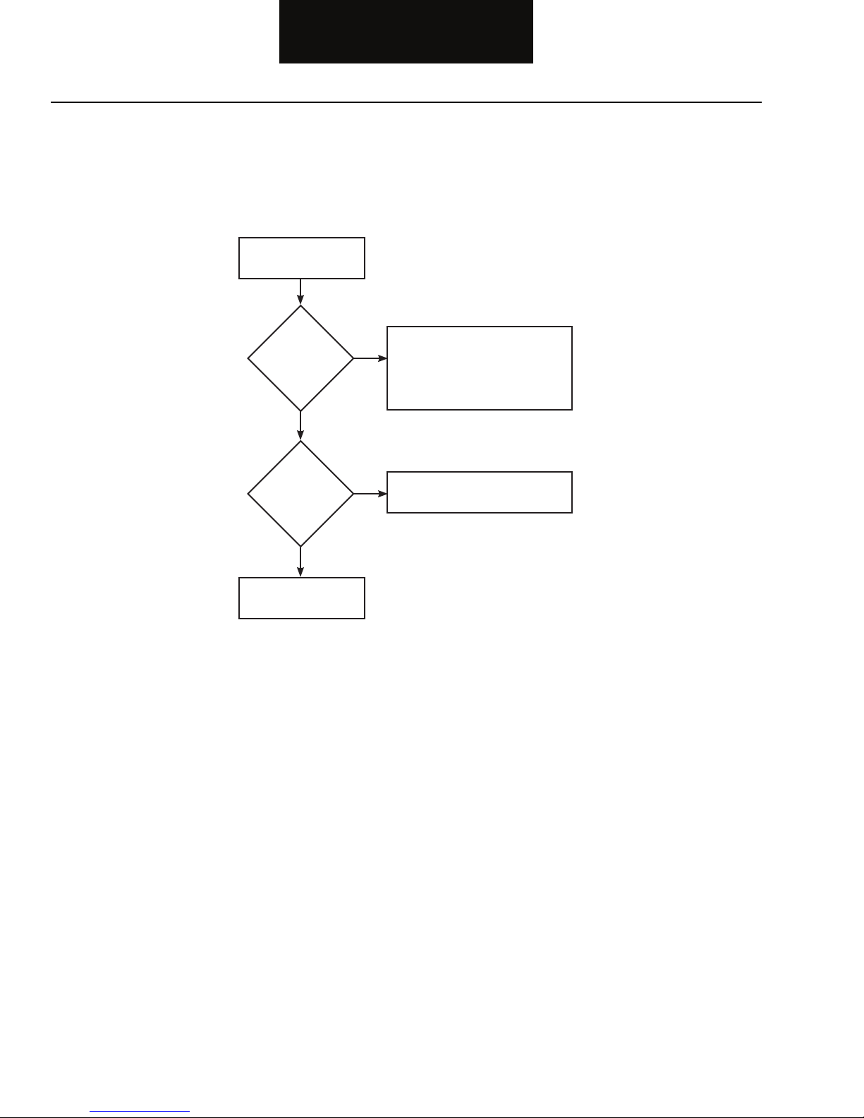
Follow the fl owchart below for all Bendix™ VORAD® system failures. Perform the tests and procedures as directed by the fl owchart.
Key On
Is the
Operator Display
Unit lamp lit?
YES
Is Driver
Experiencing System
Problems?
NO
Test Complete.
NO
YES
Perform Electrical Pretest
•
(page 2-1)
Perform Power-up Sequence Test
•
(page 2-5)
See System Isolation Procedures
•
(page 3-1)
1-2
Page 5
Electrical Pretest
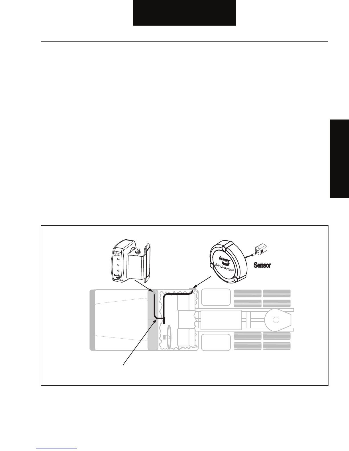
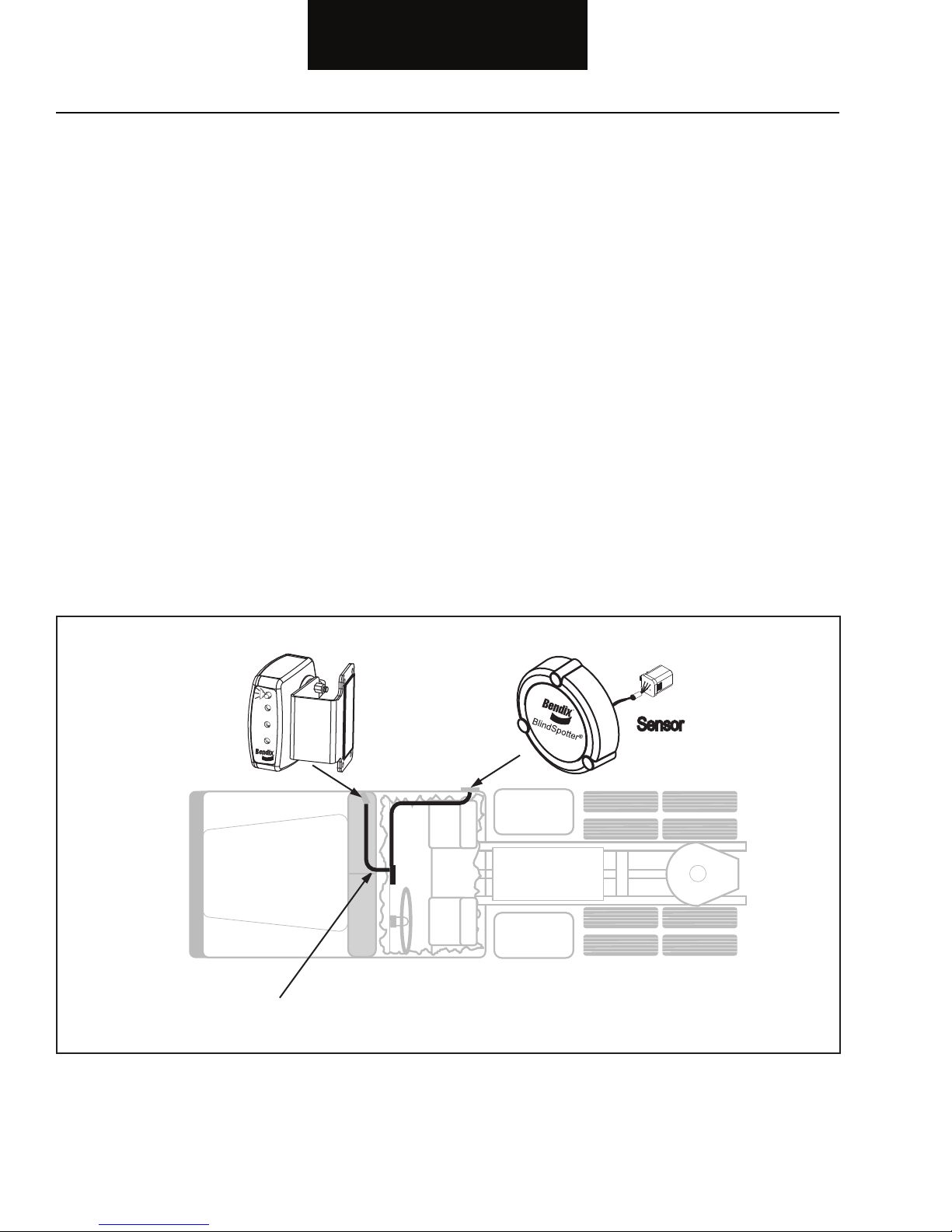
Harness
P2 SOD
Operator
Display Unit
(ODU)
Sensor
Fault Isolation Procedures
Overview
The pretest verifi es the basic electrical inputs before testing
individual circuits.
Detection
There is no detection process specifi cally for the basic electrical
supply. However, failures of this type are generally detected by the
Bendix™ VORAD® system or the driver as some other type of fault
code or symptom.
Fallback
There is no fallback for the electrical pretest, however, it may affect
other systems.
Required Tools
• Basic Hand Tools
• Digital Volt/Ohm Meter
• Troubleshooting Guide
Possible Causes
This pretest can be used for any of the following:
• Corroded Power Contacts
• Blown Fuse
• Wiring Harness
• Low Batteries
Electrical Pretest
2-1
Page 6
Fault Isolation Procedures
OHMS
GROUND
V ACOM
1
2
3
4
5
6
VOLT
V ACOM
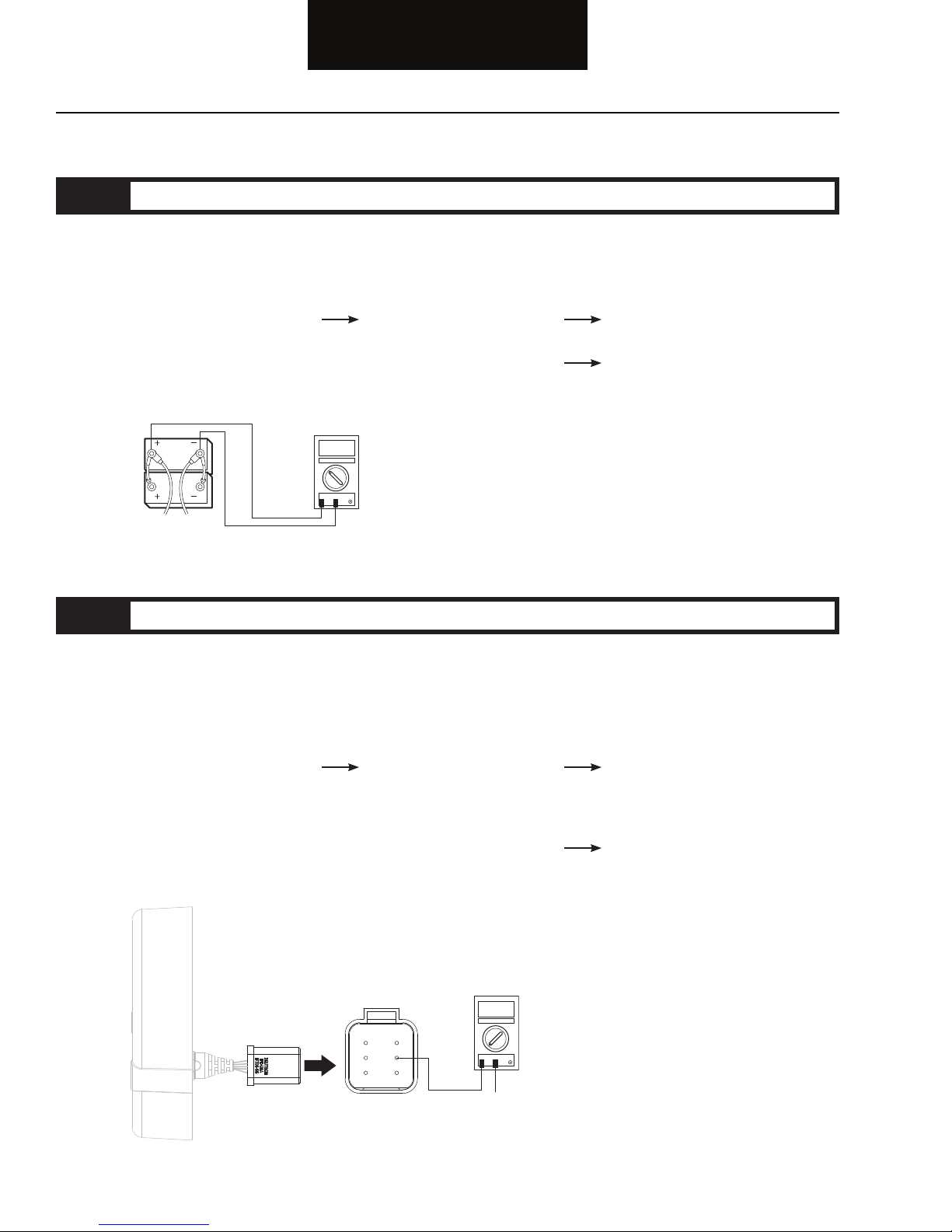
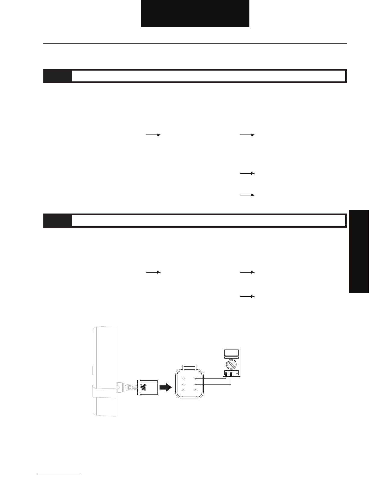
Electrical Pretest
Step A Procedure Condition Action
1. Key off.
2. Inspect starter/battery
connections for integrity.
3. Measure voltage across
battery.
If voltage is 11 to 13 volts
on a 12 volt system or 22 to
26 on a 24 volt system
If voltage is outside of
range
Go to Step B.
Repair or replace batteries and
charging system as required.
Repeat this step.
Step B Procedure Condition Action
1. Key off.
2. Disconnect negative (-) battery
cable.
3. Disconnect the sensor J2 harness.
4. Measure resistance
between sensor harness
J2 pin 2 and ground.
If resistance is 0 to .5 ohms
Go to Step C.
2-2
If resistance is outside of
range
Repair ground path to system.
Go to Step A.
Page 7
Fault Isolation Procedures
OHMS
GROUND
V ACOM
1
2
3
4
5
6
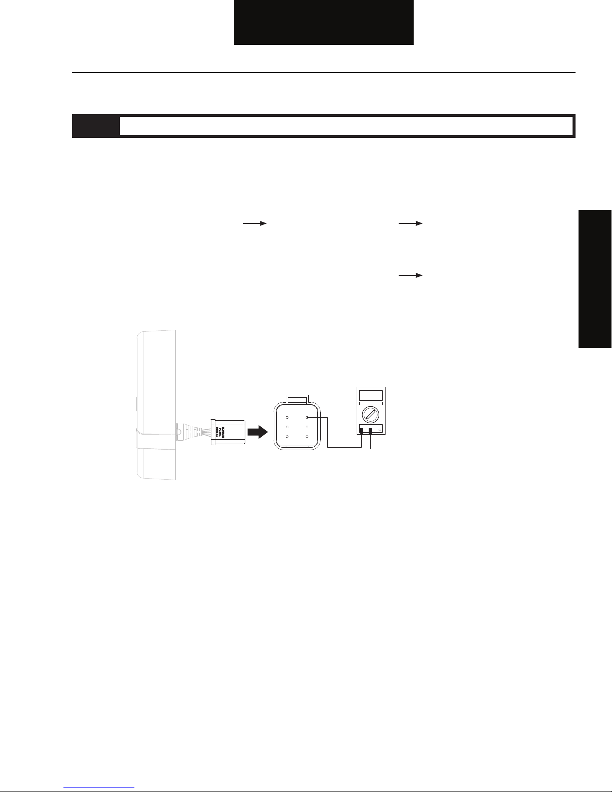
Electrical Pretest, continued
Step C Procedure Condition Action
1. Key off.
2. Connect negative (-) battery
cable.
3. Key on.
4. Measure voltage
between sensor harness
J2 pin 1 and ground.
If voltage is within .5 volts
of battery voltage
If voltage is outside of
range
Test complete.
Electrical Pretest
Repair power path to system.
Fuse may be blown. Reconnect all
connectors. Go to Step A.
2-3
Page 8
Power-Up Sequence Test
Harness
P2 SOD
Operator
Display Unit
(ODU)
Sensor
Fault Isolation Procedures
Overview
The failure during the power-up self-check indicates a system
failure.
Detection
The power-up self-check is performed automatically each time the
key is turned on. Turn the key on and watch the Operator Display
Unit (ODU). If lights on the ODU remain on after 15 seconds, or
never come on, the self-check has failed.
Fallback
If self-check fails, the product can not perform any operations.
Required Tools
• Digital Volt/Ohm Meter
Possible Causes
• Sensor
• Operator Display Unit
• Vehicle Harness
2-4
Page 9
Fault Isolation Procedures
VOLT
V ACOM
1
2
3
4
5
6
Power-Up Sequence Test
Step A Procedure Condition Action
1. Before performing this test, the
Electrical Pretest must pass.
2. Clear area around sensor of objects.
3. Key on.
4. Observe the Operator
Display Unit.
If both LED lights turn on
for .5 seconds – followed by
Test complete.
the red LED for 5 seconds –
followed by a continuous
yellow light
If lights fail to turn on
If lights turn on and stay on
Go to Step B.
Go to Step D.
Step B Procedure Condition Action
1. Key on.
2. Disconnect sensor harness J2.
3. Key on.
4. Measure voltage
between sensor harness
J2 pins 1 and 2.
If voltage is between 10
and 14 volts
If voltage is outside of
range
Go to Step C.
Repair harness. Go to Step V.
Power-Up Sequence Test
2-5
Page 10

Fault Isolation Procedures
VOLT
V ACOM
ODU P1
1
2
3
4
Power-Up Sequence Test, continued
Step C Procedure Condition Action
1. Key off.
2. Disconnect Operator Display
Unit from harness J1.
3. Key on.
4. Measure voltage between
sensor harness J2
pins 1 and 2.
If voltage is between 10 and
14 volts
If voltage is outside of range
Replace ODU. Go to Step V.
Replace sensor. Go to Step V.
2-6
Page 11

Fault Isolation Procedures
OHMS
V ACOM
1
2
3
4
ODU P1
1
2
3
4
5
6
Power-Up Sequence Test, continued
Step D Procedure Condition Action
1. Key off.
2. Disconnect sensor harness J2.
3. Disconnect Operator Display Unit
from harness J1.
4. Measure resistance between
J1 pin 3 and J2 pin 3.
If resistance is between
0 and 0.3 ohms
If resistance is outside of range
Replace ODU. Go to Step E.
Replace sensor. Go to Step V.
Power-Up Sequence Test
2-7
Page 12

Fault Isolation Procedures
VOLT
V ACOM
ODU P1
1
2
3
4
Power-Up Sequence Test, continued
Step E Procedure Condition Action
1. Key off.
2. Disconnect Operator Display
Unit from harness J1.
3. Key on.
4. Measure voltage between
sensor harness J2
If voltage is between 10 and
14 volts
Replace ODU. Go to Step V.
pins 1 and 2.
If voltage is outside of range
Replace Sensor. Go to Step V.
Step V Procedure Condition Action
1. Key off.
2. Reconnect all connectors.
3. Key on.
4. Drive vehicle to determine
if problem has been
corrected.
2-8
If problem is corrected
If problem is not corrected
Test complete.
Return to Step A to fi nd error
in testing.
Page 13

Symptom Isolation Procedures
Harness
P2 SOD
Operator
Display Unit
(ODU)
Sensor
Operator Display Unit Audible Indictor
(Buzzer) Not Functioning
Overview
This symptom-driven test is performed when the system fails to
detect objects properly.
Detection
The symptom is observed by the driver when:
1) objects closer than ten (10) feet are detected,
2) when the turn signal is activated, and
3) when no audible sound is heard.
Fallback
There is no fallback mode for this symptom. The system will not
operate properly.
Required Tools
• Digital Volt/Ohm Meter
Possible Causes
This fault can be caused by any of the following:
• Operator Display Unit
• Vehicle Harness
Operator Display
Audio Test
3-1
Page 14

Symptom Isolation Procedures
OHMS
V ACOM
ODU P1
To Turn Signal Source
1
2
3
4
Operator Display Unit Audible Indictor (Buzzer) Not Functioning
Step A Procedure Condition Action
1. Key off.
2. Active turn signal.
3. Place a target between 3
and 10 feet directly in
front of the sensor.
Note: If both LEDs are
illuminated, go to the
appropriate isolation
If the Operator Display Unit
has red LED on and buzzer
sounds
If the Operator Display Unit
has red LED on only
(no sound)
Test complete.
Go to Step B.
procedure.
Step B Procedure Condition Action
1. Key off.
2. Disconnect Operator Display Unit
from harness J1.
3. Measure resistance between
sensor harness J1 pin 4
and turn signal source.
If resistance is between
0 and 0.3 ohms
If resistance is outside
of range
Go to Step C.
Repair wiring harness.
Go to Step V.
3-2
Page 15

Symptom Isolation Procedures
VOLT
V ACOM
ODU P1
1
2
3
4
Operator Display Unit Audible Indictor (Buzzer) Not Functioning, continued
Step C Procedure Condition Action
1. Key off.
2. Disconnect Operator Display Unit
from harness J1.
3. Measure resistance between
display harness J1 pins
2 and 4.
If resistance is between
0 and .5 ohms
If resistance is outside of
range
Go to Step D.
Repair wiring harness.
Go to Step V.
Operator Display
Audio Test
3-3
Page 16

Symptom Isolation Procedures
VOLT
V ACOM
ODU P1
1
2
3
4
Operator Display Unit Audible Indictor (Buzzer) Not Functioning, continued
Step D Procedure Condition Action
1. Key off.
2. Disconnect Operator Display
Unit from harness J1.
3. Key on.
4. Activate turn signal.
5. Measure voltage between
display harness J1
If voltage is between 10 and
14 volts
Replace display. Go to Step V.
pins 2 and 4.
If voltage is outside of range
Repair wiring harness.
Go to Step V.
Step V Procedure Condition Action
1. Key off.
2. Reconnect all connectors.
3. Key on.
4. Drive vehicle to determine
if problem has been
corrected.
3-4
If problem is corrected
If problem is not corrected
Test complete.
Return to Step A to fi nd error
in testing.
Page 17

Symptom Isolation Procedures
Harness
P2 SOD
Operator
Display Unit
(ODU)
Sensor
Side Sensor Not Detecting Targets
Overview
This symptom driven test is performed when the system fails to
detect objects properly.
Required Tools
Detection
The symptom is observed by the driver when objects at three (3)
to ten (10) feet are not detected. The yellow light also continuously
illuminates when the sensor has failed.
Fallback
There is no fallback mode for this symptom. The Sensor will not
operate properly.
• None
Possible Causes
This fault code can be caused by any of the following:
• Sensor
• Operator Display Unit
3-5
Detection Test
Side Sensor
Page 18

Symptom Isolation Procedures
Side Sensor Not Detecting Targets
Step A Procedure Condition Action
1. Clear area around sensor of
objects.
2. Key on.
3. Allow Operator Display
Unit to go through selftest and shows no
targets (yellow LED
light should be on).
If both LED lights turn on
for .5 seconds – followed by
red LED for 5 seconds –
followed by a continuous
yellow light
If only the yellow LED light
turns on for .5 seconds,
followed by a continuous
yellow light
If both LED lights turn on
for .5 seconds, followed by
continuous yellow and red
lights
Go to Step B.
Replace Operator Display Unit.
Go to the “Power-Up Sequence
Test” on page 2-4.
Step B Procedure Condition Action
1. Key on.
2. Place a target 3 to 10
feet directly in front of
the Sensor.
If the Operator Display Unit
indicates that a target is
detected (red light on)
Go to Step V.
Step V Procedure Condition Action
1. Key off.
2. Reconnect all connectors.
3. Drive vehicle to
determine if problem
has been corrected.
3-6
If the Operator Display Unit
does not indicate a target is
present (yellow light on)
If complaint has been
repaired
If complaint has not
been repaired
Replace sensor.
Test complete.
Return to Step A to fi nd
error in testing.
Page 19

Symptom Isolation Procedures
Harness
P2 SOD
Operator
Display Unit
(ODU)
Sensor
Side Sensor Continuous
Side Sensor Continuously Detecting
Targets
Overview
This symptom driven test is performed when the system
continuously detects objects.
Detection
The symptom is observed by the driver when sensor continuously
detects targets.
Fallback
There is no fallback mode for this symptom. The Sensor will not
operate properly.
Detection Test
Required Tools
• None
Possible Causes
This fault code can be caused by any of the following:
• Sensor
• Operator Display Unit
3-7
Page 20

Symptom Isolation Procedures
Side Sensor Continuously Detecting Targets
Step A Procedure Condition Action
1. Clear area around sensor
of objects.
2. Key on.
3. Allow Operator Display
Unit to go through self-test
and shows no targets
(yellow LED light should
be on).
If both LED lights turn on
for .5 seconds – followed by
a red LED for fi ve (5) seconds –
followed by a continuous
yellow light
If both LED lights turn on
for .5 seconds, followed by
a continuous red light
If only red LED lights
Go to Step V.
Go to Step B.
Replace Operator Display Unit.
Step B Procedure Condition Action
1. Key on.
2. Remove Sensor from mounting
position.
3. Move Sensor out away from the
vehicle and place in an open area.
4. Key on.
5. Allow Operator Display
Unit to go through self-test
and shows no targets
(yellow LED light should
be on).
3-8
If both LED lights turn on
for .5 seconds – followed by
a red LED for fi ve (5) seconds –
followed by a continuous
yellow light
If both LED lights turn on
for .5 seconds, followed by
a continuous red light
Reposition sensor on vehicle
to allow clear detection zone.
Go to Step V.
Replace sensor. Go to Step V.
Page 21

Symptom Isolation Procedures
Side Sensor Continuous
Side Sensor Continuously Detecting Targets, continued
Step V Procedure Condition Action
1. Key off.
2. Reconnect all connectors.
3. Drive vehicle to
determine if problem
has been corrected.
If complaint has been
repaired
If complaint has not been
repaired
Test complete.
Return to Step A to fi nd error
in testing.
Detection Test
3-9
Page 22

Symptom Isolation Procedures
Side Sensor Continuously Detecting Targets, continued
3-10
This page left blank intentionally.
Page 23

Wiring Diagrams
J2 SOD
ODU PWR
ODU GND
COM M
PWR
GND
SIDE OBJECT
DETECTION SENSOR
P2 SOD
J1 ODU
ODU PWR
ODU GND
ODU COMM
TUR N SIGN AL
OPERATOR
DISPLAY
UNIT
ODU P1
INTERCONNECT
HARNESS
TURN SGNL
IGNI TION
GROU ND
1
2
3
4
5
6
1
2
3
4
CONNECTOR REAR
CONNECTOR REAR
BlindSpotter
®
Appendix
Appendix
A-1
Page 24

Appendix
J2
J1
3
2
1
4
5
6
2
1
3
4
J1 O D U
DISPLAY
SENSOR
J2 S O D
72 INCHES
240 INCHES
1
23456
342
1
PW R
GN D
CO MM
OD U PW R
OD U GN D
RE D
BL AC K
WH IT E
DK G RE EN
BR OW N
RE D
BL AC K
IG NI TI ON
GR OU ND
DK G RE EN
BR OW N
WH IT E
OR AN GE
TU RN S IGN AL
OD U PW R
OD U GN D
OD U CO MM
TU RN S IG
SI DE
SE NS OR
OP ER AT OR
DI SP LA Y
UN IT
WI RI NG DI AG RA M
IGN ITION
GRO UND
TURN SGNL
CONNECTOR FRONT
CONNECTOR FRONT
A-2
Page 25

Appendix
ODU P1
2.0
.70
2.3
2.1
1.0
2.0
2.8
BRACKET CAN
BE BENT± 15°
10°
FOUR #4
METAL SCREWS
4 X 0 .125 THRU
MTG. HOLES
ADHESIVE BACKING
1.6
1.2
39" ±3"
Appendix
A-3
Page 26

5.6
5.36
1.25 MTG. HOLE TO
CLEAR CONNECTOR
1.38
0.9
0.82
2.04 2.04
3.53
P2 SOD
P2 SOD
1) USE 3 #10-24 X 1 1/2" S.S.
BUTTON HEAD CAP SCREWS FOR
MOUNTING.
2) TORQUE TO 22 IN/LBS.
MADE IN USA
PART
NUMBER
*86989492*
NO.
SERIAL
000003
FCC ID: OXZSTDPREVIEW
This device complies with part 15 of the FCC Rules.
Operation is subject to the following two conditions:
1) This device may not cause harmful interference and
2) This device must accept any interference received.
Including interference to cause undesired operation.
3.2
5.36
0.25
BlindSpotter
®
Appendix
A-4
Page 27

Appendix
Appendix
This page left blank intentionally.
Page 28

Page 29

Page 30

901 Cleveland Street • Elyria, OH 44035 • 1-800-AIR-BRAKE • www.bendix.com
BW2860 ©2011 Bendix Commercial Vehicle Systems LLC, a member of the Knorr-Bremse Group • All Rights Reserved • 09/11
 Loading...