

Page 1
®
Bendix® MC-12™ Modulator Controller Assembly
SD-13-4762
™
EC-12
CONTROLLER
™
M-12
MODULATOR
DELIVERY
PORTS
(4 VERTICAL)
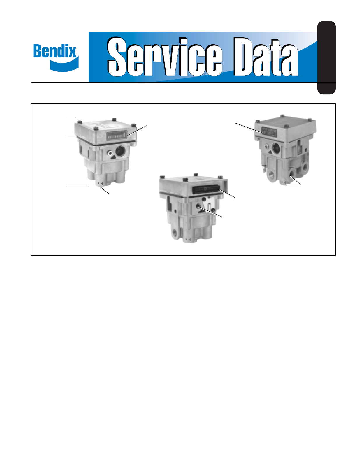
FIGURE 1 - MC-12™ MODULATOR CONTROLLER ASSY.
DIAGNOSTIC
DISPLAY
DESCRIPTION
The Bendix® MC-12™ modulator trailer antilock system is
designed to improve vehicle stability by reducing wheel lock
up during aggressive braking. Like Bendix's tractor antilock,
the trailer system can provide single or tandem axle control.
The main component is nipple mounted to a reservoir, so
the system requires no special trailer modifications.
The trailer antilock system consists of the following: MC-12
modulator/controller, WS-20™ wheel speed sensors,
electrical connectors and wiring. The MC-12™ modulator is
the main component. It houses the EC-12™ electronic
controller and the M-12™ modulator, which cont ains solenoids
and a standard relay valve.
The EC-12™ controller houses the electronics that regulate
the trailer antilock system and also incorporates a diagnostic
display window and a 14 pin connector.
DIAGNOSTIC
DISPLAY
DELIVERY
14 PIN
CONNECTOR
CONTROL
PORT
(2 VERTICAL
HORIZONTAL)
wheel end send wheel speed information to the EC-12
controller through the 14 pin connector. The sensors are
actually AC. generators. They house magnets, which create
a magnetic field. When the field is interrupted by an irregular
surface, such as a tone ring, AC. volt age is produced. The
frequency of voltage increases or decreases as wheel speed
increases or decreases.
During normal, non antilock operation, the M-12™ modulator's
inlet solenoid is open, and the exhaust solenoid is closed.
™
In this condition, the M-12™ modulator functions as a regular
R-12™ relay valve. It receives a control signal from the foot
valve, which passes through the open inlet solenoid and
causes the brakes to apply in proportion to the amount of
control pressure.
If wheel lock up is impending, the EC-12™ controller
commands the solenoids to modulate brake chamber
pressure on the axle(s) in which the system is installed.
PORTS
2
™
The EC-12™ controller mounts to the M-12™ modulator with
four bolts, and it is internally connected to the solenoids by
a four pin connector. The solenoids are the interface between
the EC-12™ controller electronic signals and the
pneumatically operated modulator. Sensors mounted at the
The MC-12™ modulator/controller receives its power from
the vehicle's stop light circuit (pin 4 on the standard seven
pin connector—red). The power enters the EC-12™ controller
at pin A and (optionally) pin B from the auxiliary terminal
(blue wire) of the trailer’s 7 pin connector.
1
Page 2
Seven Conductor Antilock Wire Gauge
Pin (Wire Connector Wire Single/
Connector No.) Letter Color Lamp and Signal Circuits Dolly Double Triple
1 1 C White Ground Return To Towing Vehicle 12 10 8
2 2 - Black Clearance, Side Marker and Identification Lamps 12 12 12
3 3 - Yellow Left Hand Turn Signal and Hazard Signal Lamps 12 12 12
4 4 - Red Stop Lamps 10 10 10
5 5 - Green Right Hand Turn Signal and Hazard Signal Lamps 12 12 12
6 6 - Brown Tail, Clearance, Side Marker and License Plate Lamps 12 12 12
7 7 B* Blue Auxiliary, Dome, Etc. or constant Antilock power 12 12 12
4 9 A Red Antilock Power From Stop Lamp 10 10 10
- 8 D Yellow Trailer Mounted Status Light 14/16 14/16 14/16
- 10/11 N/P - Wheel Speed Sensor 16/18 16/18 16/18
- 12/13 M/L - Wheel Speed Sensor 16/18 16/18 16/18
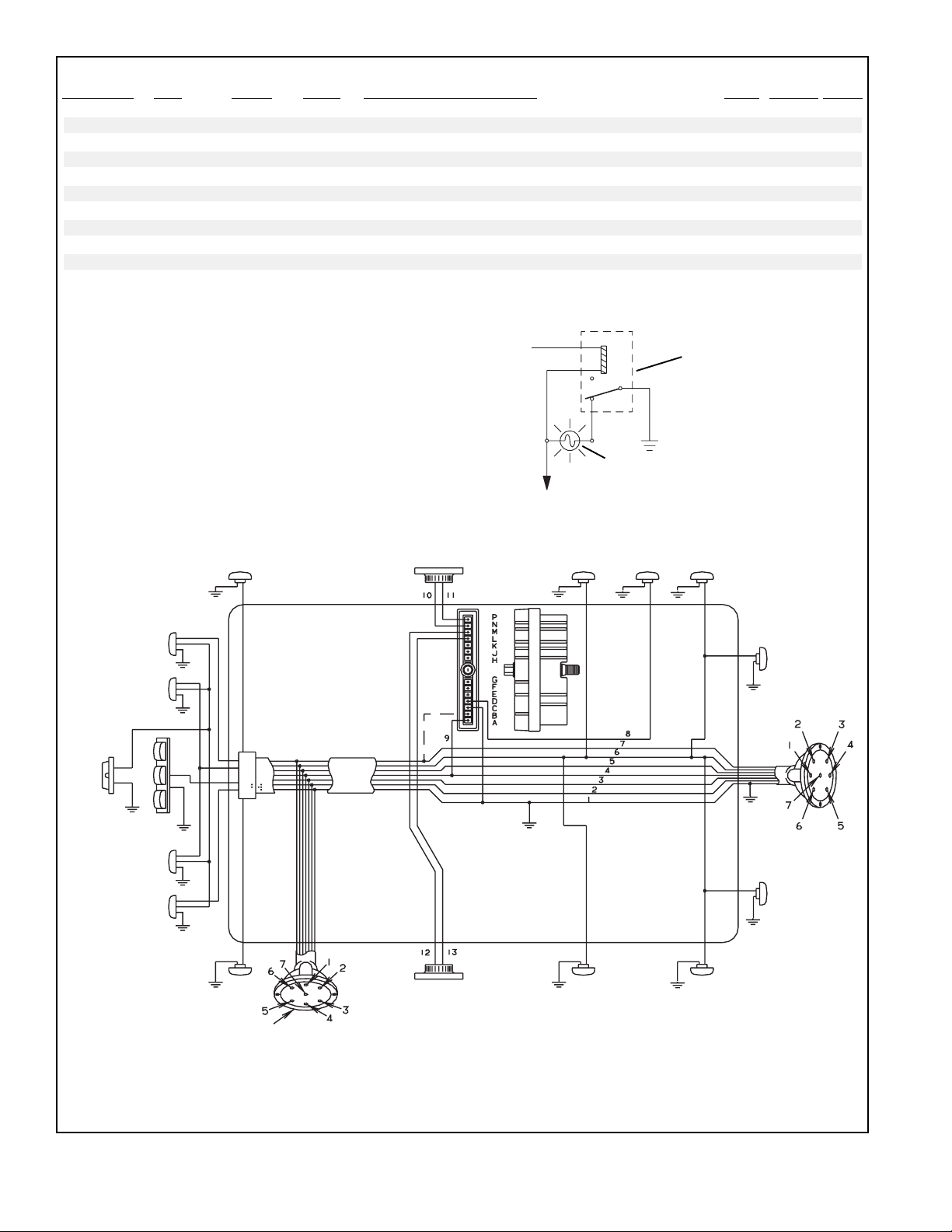
* Antilock Connector Pin B is an option and is used to provide constant power to the MC-12™ modulator during trailer operation.
CI/Directional
Stop & Tail
License Plate
The relay illustrated to the right is used when
a tractor, dash mounted status lamp for the
trailer antilock system is desired. Like the
trailer mounted status lamp, this is an option
and is not required.
Marker
MC-12
Wheel
Speed
Sensor
To Pin “G” on
™
Modulator
Connector
To Power Side of
Tractor Ignition
Tractor Electrical
Relay
Tractor Dash Mounted
Trailer Antilock Status
Lamp
Trailer
Mounted
Status
Marker Marker
Indicator
Clearance
Stop & Tail
CI/Directional
Marker
Rear 7 Pin
Connector
Plug (See
Note)
Wheel
Speed
Sensor
Note:
The rear 7 pin connector plug is for Dolly operations for Doubles & Triples
FIGURE 2 - MC-12™ MODULATOR TRAILER SYSTEM WIRING SCHEMATIC
2
Clearance
Marker Marker
Page 3
System ground (pin 1 on the seven pin connector—white)
enters the MC-12™ modulator at pin C.
Each wheel speed sensor sends the MC-12™ modulator its
AC. signal through a pair of wires. The MC-12™ modulator
pins for the sensors are L-M and N-P.
directs the driver to the problem area. A series of LEDs on
the EC-12™ controller indicate the status of power, EC-12
controller, wheel speed sensors, M-12™ modulator solenoids,
or voltage level.
™
The MC-12™ modulator can send a +12v failure signal to the
optional trailer mounted status light through pin D. The status
light indicates the condition of the trailer antilock system. In
addition, the MC-12™ modulator can send a grounding signal
through its pin J to an optional tractor, dash mounted st atus
lamp. During start up, when the trailer brakes are actuated,
trailer antilock immediately runs a self check. The status
light flashes once and then goes off. Should a problem occur ,
the antilock system disengages and returns to normal
R-12™ relay valve operation.
If the status light comes on and remains on when the trailer
brakes are actuated, a system problem has occurred. The
EC-12™ controller contains a diagnostic window, which
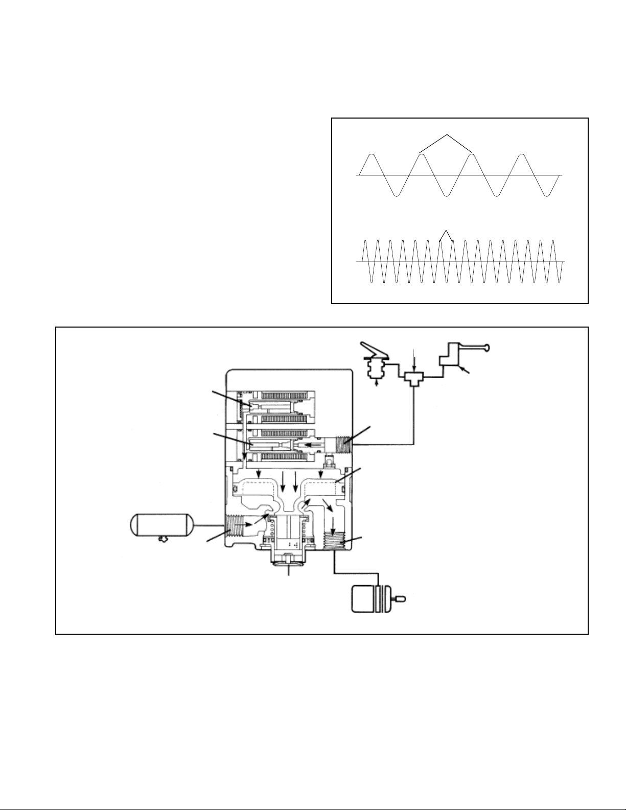
EXHAUST
SOLENOID
SUPPLY
SOLENOID
PEAK TO PEAK
LOW SPEED
PEAK TO PEAK
HIGH SPEED
FIGURE 3 - SPEED SENSOR VOL TAGE CYCLE OUTPUT
DOUBLE
CHECK
TRAILER
CONTROL
BRAKE
VALVE
CONTROL
SUPPLY
EXHAUST
FIGURE 4 - APPLYING: NORMAL SERVICE APPLICATION
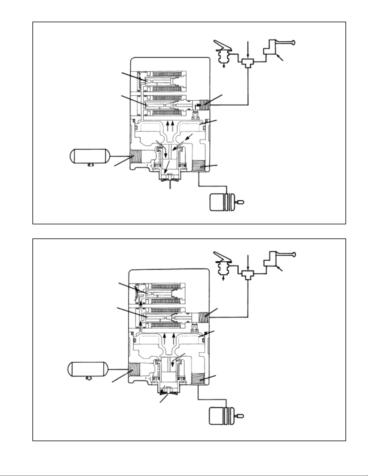
OPERATION
APPLYING: Normal Service Application
When a normal service brake application is made, and the
EC-12™ controller does not sense impending wheel lock up,
control air pressure from the brake valve enters the modulator
PISTON
DELIVERY
SERVICE
BRAKE
CHAMBER
control port. The air passes through the supply solenoid
and acts on the modulator's piston. The piston closes the
modulator exhaust and opens the inlet, delivering supply air
out the delivery ports.
3
Page 4
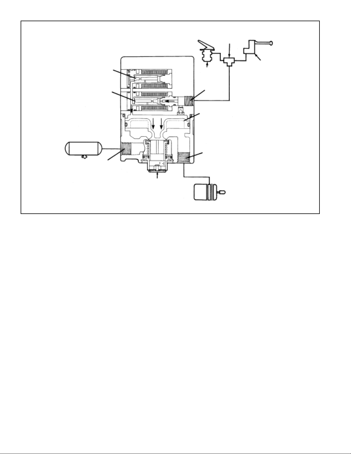
DOUBLE
CHECK
EXHAUST
SOLENOID
SUPPLY
SOLENOID
SUPPLY
EXHAUST
FIGURE 5 - BALANCED POSITION: NORMAL SERVICE APPLICATION
BRAKE
VALVE
CONTROL
PISTON
DELIVERY
TRAILER
CONTROL
SERVICE BRAKE
CHAMBER
BALANCED POSITION: Normal Service Application
The modulator reaches a balanced position when control
pressure acting upon the top side of the piston approaches
that of the air acting upon the underside of the piston. The
piston moves upward and closes the inlet valve, while the
exhaust remains closed. This prevents the modulator from
delivering or exhausting air.
EXHAUSTING: Normal Service Application
When the brake valve is released, control pressure exhausts
through the supply solenoid and the check valve in the
solenoid housing and out the exhaust port of the brake valve.
As the piston moves upward, the modulator's exhaust opens,
allowing air from the piston's underside to exhaust through
the modulator exhaust port.
ANTILOCK MODE: Solenoids Activated
If a service brake application is made and the EC-12
controller senses wheel lockup, it will command the antilock
system to alter the service brake application.
When activated, shuttles within the solenoids alter the
application and exhaust of control air pressure. The supply
solenoid closes, preventing control line pressure from entering
the modulator. Then the exhaust solenoid opens, allowing
control pressure to exhaust from the top side of the piston
through the exhaust port of the solenoid assembly. This
activity occurs in a pulsating manner, simulating "pumping
of the brakes."
PREVENTIVE MAINTENANCE
1. Every 3 months; 25,000 miles; or 900 operating hours
perform SERVICE CHECKS.
2. Every twelve months; 100,000 miles; or 3600 operating
hours, disassemble the relay valve portion of the M-12
Modulator and clean parts with mineral spirits. DO NOT
DISASSEMBLE THE SOLENOID ASSEMBL Y . Replace
all rubber parts and any parts worn or damaged. Check
™
for proper operation before placing vehicle in service.
4
Page 5
EXHAUST
SOLENOID
DOUBLE
CHECK
TRAILER
CONTROL
BRAKE
VALVE
SUPPLY
SOLENOID
SUPPLY
EXHAUST
FIGURE 6 - EXHAUSTING: NORMAL SERVICE APPLICATION
CONTROL
PISTON
DELIVERY
SERVICE BRAKE
CHAMBER
DOUBLE
CHECK
EXHAUST
SOLENOID
SUPPLY
SOLENOID
SUPPLY
EXHAUST
TRAILER
CONTROL
BRAKE
VALVE
CONTROL
PISTON
DELIVERY
SERVICE BRAKE
CHAMBER
FIGURE 7 - ANTILOCK MODE: SOLENOIDS ACTIVATED
5
Page 6
SERVICE CHECKS
Ensure that all wiring and connectors are secure and free
from visible damage. Although the MC-12™ modulator
assembly contains self check diagnostics, the LED (Light
Emitting Diode) display should be inspected to ensure that
the LEDs are functional. With the trailer brakes actuated, a
magnet (800 gauss; capable of picking up 3 ounces) held to
the LED reset area should cause all of the LEDs to illuminate.
If one or more of the LEDs DO NOT ILLUMINA TE and the
optional status light indicates proper system function, the
non illuminated LED(s) should be noted for future reference.
Although the diagnostic capabilities will be limited, the
system will continue to function as designed.
The MC-12™ modulator assembly monitors the electronics
of the system upon initial trailer brake application. However,
the vehicle should be road tested periodically to verify proper
solenoid function. The solenoids can be tested by making
an aggressive trailer stop from a speed of 20 m.p.h. When
an antilock stop is made, solenoid pulsation creates an
audible burst of air, which can be heard from the out side of
the trailer.
WARNING! PLEASE READ AND FOLLOW
THESE INSTRUCTIONS TO AVOID
PERSONAL INJURY OR DEATH:
When working on or around a vehicle, the following
general precautions should be observed at all
times.
1. Park the vehicle on a level surface, apply the
parking brakes, and always block the wheels.
Always wear safety glasses.
2. Stop the engine and remove ignition key when
working under or around the vehicle. When
working in the engine compartment, the engine
should be shut off and the ignition key should be
removed. Where circumstances require that the
engine be in operation, EXTREME CAUTION should
be used to prevent personal injury resulting from
contact with moving, rotating, leaking, heated or
electrically charged components.
3. Do not attempt to install, remove, disassemble or
assemble a component until you have read and
thoroughly understand the recommended
procedures. Use only the proper tools and observe
all precautions pertaining to use of those tools.
4. If the work is being performed on the vehicle’s air
brake system, or any auxiliary pressurized air
systems, make certain to drain the air pressure from
all reservoirs before beginning
ANY work on the
vehicle. If the vehicle is equipped with an AD-IS
air dryer system or a dryer reservoir module, be
sure to drain the purge reservoir.
5. Following the vehicle manufacturer’s
recommended procedures, deactivate the electrical
system in a manner that safely removes all
electrical power from the vehicle.
6. Never exceed manufacturer’s recommended
pressures.
7. Never connect or disconnect a hose or line
containing pressure; it may whip. Never remove a
component or plug unless you are certain all
system pressure has been depleted.
8. Use only genuine Bendix® replacement parts,
components and kits. Replacement hardware,
tubing, hose, fittings, etc. must be of equivalent
size, type and strength as original equipment and
be designed specifically for such applications and
systems.
9. Components with stripped threads or damaged
parts should be replaced rather than repaired. Do
not attempt repairs requiring machining or welding
unless specifically stated and approved by the
vehicle and component manufacturer.
10. Prior to returning the vehicle to service, make
certain all components and systems are restored to
their proper operating condition.
®
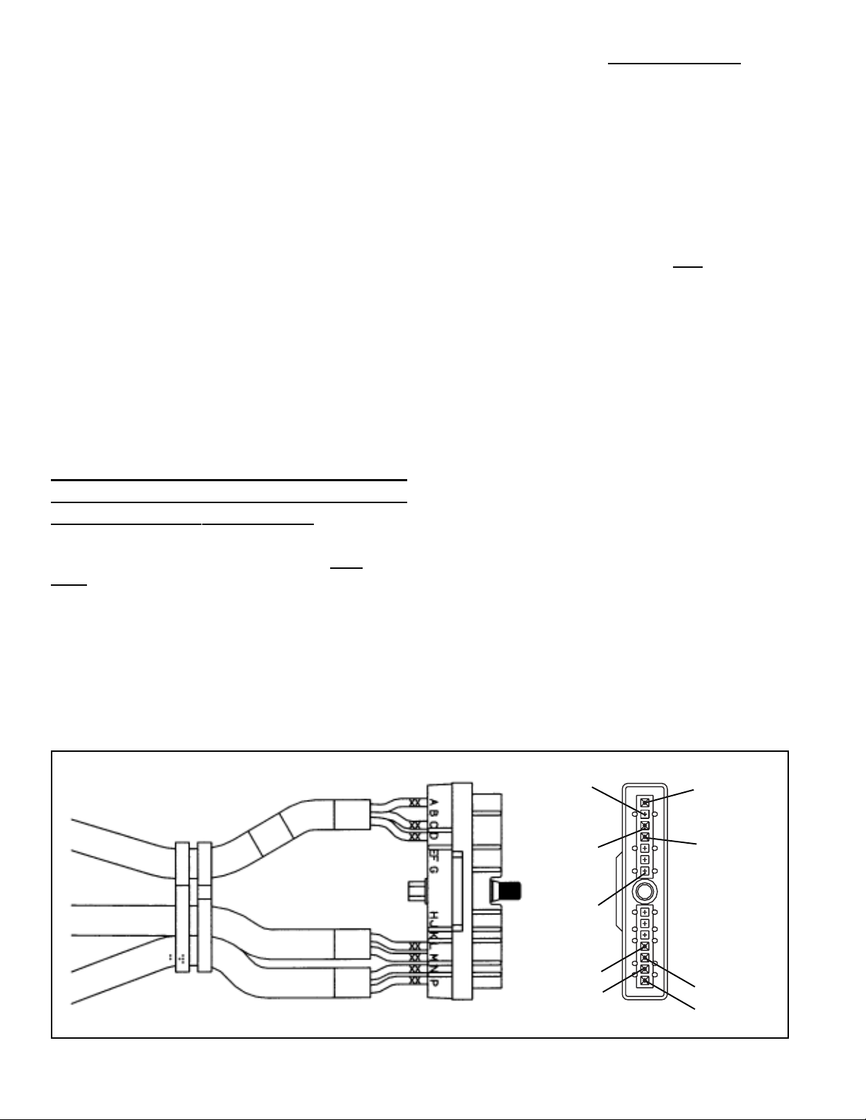
FIGURE 8 - ELECTRICAL CONNECTOR
6
OPTIONAL
CONSTANT
POWER
(TRACTOR
IGNITION)
GROUND
OPTIONAL
TRACTOR
MOUNTED
STATUS
LIGHT
SENSOR 2
SNS 2
SENSOR 1
SNS 1
A
B
C
D
E
F
G
H
J
K
L
M
N
P
STOPLIGHT
SWITCH
POWER
OPTIONAL
TRAILER
MOUNTED
STATUS
LIGHT
SENSOR 2
SNS 2
SENSOR 1
SNS 1
Page 7

REMOVAL OF THE MC-12™ MODULATOR
ASSEMBLY
1. Remove and identify all air lines connected to the unit.
2. Disconnect the 14 pin connector from the unit by
loosening its screw and pulling the connector away from
its socket.
3. Remove and save the mounting hardware connecting
the MC-12™ modulator to the vehicle.
4. Prior to disassembly, remove as much contamination
as possible from the exterior of the assembly . Be sure
to keep the contamination away from the open ports.
INSTALLATION OF THE MC-12
™
MODULA T OR ASSEMBLY
1. Replace the MC-12™ modulator assembly on the vehicle
using the hardware saved during removal. Connect the
air lines to the proper ports, as identified during removal.
Connect the 14 pin connector into the controller and
tighten the screw.
1
7
2
4
5
6
DISASSEMBLY
The following disassembly and assembly procedure is
presented for reference purposes and presupposes that a
major rebuild of the antilock valve is being undertaken. Several
replacement parts and maintenance kits are available which
do not require full disassembly. The instructions provided
with these parts and kits should be followed in lieu of the
instructions presented here.
CAUTION: The MC-12™ modulator may be lightly clamped
in a bench vise during disassembly . However, over clamping
will result in damage, leakage, and/or malfunction. If a vise
is to be used, position the MC-12™ modulator so the jaws
bear on the flat area of the supply port and its opposing side
of the body .
1. Remove the EC-12™ controller (1) from the M-12
modulator by removing the controller's four mounting
bolts.
2. Lift the controller off the M-12™ modulator and detach
the wire harness from the base of the controller by
depressing the lock tab on the side of the connector
and pulling the connector from its socket in the controller.
Remove the gasket (7) from the EC-12™ controller body.
NOTE: If replacement of the controller only is required,
proceed to Step 8 of assembly.
3. Remove sealing ring (4) from the protrusion on the bottom
of the solenoid assembly .
4. Using a pair of snap ring pliers, remove retaining ring
(14). Remove the exhaust assembly (13). Remove
o-ring (12) and o-ring (11) from the l.D. and O.D.,
respectively , of the exhaust assembly .
5. Remove spring (10). Remove the inlet/exhaust assembly
(8). Remove the spring seat (9) from the inlet/exhaust
assembly.
6. Using your thumb, press the piston stem and push the
piston (6) out the opposite end of the body. Remove
o-ring (5) from the piston.
7. Discard all items that have replacement parts in the
maintenance kit.
™
9
11
13
FIGURE 9 - EXPLODED VIEW
10
12
14
CLEANING & INSPECTION
3
8
1. Using mineral spirits or an equivalent solvent, clean and
thoroughly dry all parts to be reused. Do not allow mineral
spirits to come into contact with the ECU connector or
solenoids.
2. Inspect the interior and exterior of all parts that will be
reused for severe corrosion, pitting and cracks. Superficial
corrosion and/or pitting on the exterior portion of the body
is acceptable.
3. Inspect the bores for deep scuffing or gouges.
4. Inspect the pipe threads in the body. Make certain they
are clean and free of thread sealant.
7
Page 8

5. Inspect all air line fittings and plugs for corrosion. Clean
all old thread sealant from the pipe threads.
Any component exhibiting a condition described in inspection
steps 2 to 5 should be discarded and replaced before
proceeding.
ASSEMBLY—REFER TO FIG. 9
1. Using a lubricant (Bendix Pc. No. 291126) lightly coat
all o-rings and the bores of the valve body .
2. Install spring seat (9) onto the inlet/exhaust valve (8) so
that it covers the rubber seat of the inlet/exhaust valve.
Place the inlet/exhaust valve, large diameter first, into
the M-12™ modulator's bottom bore.
3. Install spring (10) over the barrel of the inlet/exhaust valve
(8) so that one end of the spring rests on the spring seat
(9).
4. Install the o-rings (1 1 8 12) into the respective grooves of
the O.D. and l.D. of the exhaust assembly (13). Place
the large diameter of the exhaust assembly against the
spring (10) and compress the spring until the exhaust
assembly enters the bore of the body and the o-ring (1 1)
seals against the wall of the bore.
5. Depress the exhaust assembly into the bore until it
exposes the groove for the snap ring (14). Install snap
ring (14) into its groove. Make sure it is fully seated.
6. Install o-ring (5) into its groove in the piston (6). Install
piston (6) into the M-12™ modulator body. The piston
stem fits into the small hole in the center of the body .
7. Install o-ring (4) onto the protrusion on the bottom of the
M-12™ modulator solenoid assembly . Install the solenoid
assembly (2) onto the valve body . The solenoid assembly
will fit on the M-12™ modulator body in any of four
orientations, 90 degrees apart. However , if clearance is
a problem, make sure the control port is not directly
above the valve's supply port, which will be nipple
mounted to a reservoir. Secure the solenoid assembly
to the valve body with the four 1/2" bolts. Torque the
bolts to 120 150 in. Ibs.
8. Install gasket (7) onto the EC-12™ controller. Inst all the
EC-12™ controller (1) as shown in Figure 9 by plugging
the electrical connector from the solenoid assembly into
the socket in the bottom of the controller. Press in until
lock tab engages. Ensure engagement by pulling the
connector lightly . Place the controller onto the solenoid
assembly and secure with the four 1/2" bolts and lock
washers. Torque to 30 60 in. Ibs.
OPERATIONAL AND LEAKAGE TEST
1. Chock wheels. Fully charge air brake system and adjust
brakes.
2. Make several trailer brake applications and check for
prompt application and release at each wheel.
3. Check for inlet valve o-ring leakage. With the trailer
service brakes released, coat the exhaust port and the
area around the retaining ring with a soap solution. A 1"
bubble in 3 seconds is permitted.
4. Check for exhaust valve leakage. With the trailer service
brakes fully applied, coat the exhaust port with a soap
solution. A 1" bubble in 3 seconds is permitted. Coat
the outside of the modulator body to check for seal ring
leakage. No leakage is permitted.
5. If leakage is excessive around the supply and exhaust
solenoids, replace the M-12™ modulator. If excessive
leakage is detected where the solenoid assembly and
M-12™ modulator body meet, replace the M-12
modulator. If excessive leakage is detected at the exhaust
™
port, before replacing the M-12
modulator perform the
following test:
Place the vehicle in park by exhausting the air pressure
from the emergency side of the spring brake. Perform the
leakage check around the exhaust. If the air continues to
leak out the exhaust replace the M-12
™
modulator. If a leak
exists between the emergency and service sides of the spring
brake, the leakage at the exhaust will cease when air pressure
is exhausted from the emergency side of the spring brake.
The air pressure will pass from the emergency side to the
service side of the chamber, out the service inlet and out the
M-12™ modulator exhaust.
ELECTRICAL TEST
If the status light remains on after the trailer brakes have
been actuated, inspect the EC-12™ controller for illuminated
LEDs. Each LED represents a specific area.
VOL T LED (red) High/Low Voltage
MOD LED (red) M-12
SNS1 LED (red) Wheel Sensor Failure
SNS2 LED (red) Wheel Sensor Failure
CONT LED (red) EC-12
PWR LED (green) EC-12
RED LEDs INDICATE FAILURE
When the EC-12™ controller senses a failure, the red LED
corresponding to the failure mode will illuminate. A failure is
stored in memory until the problem is repaired and the
EC-12™ controller is reset. NOTE: Only the voltage LED
resets itself after the condition no longer exists.
™
Modulator Failure
™
Controller Failure
™
Controller Power
™
8
Page 9

TROUBLESHOOTING INFORMATION
PREPARATION FOR TESTING
All trailer antilock testing should be performed with a tractor
connected to the trailer.
1. Connect the tractor to the trailer and build up the air
system, on both the tractor and trailer, to governor cut
out pressure.
2. Park the combination on a level surface. Apply the tractor
parking brakes then release the trailer parking brakes
only and turn off the engine.
NOTE: Some tractors may not have the ability to release
the trailer brakes while the tractor parking brakes remain
applied. In this event, chock all wheels, build the tractor
and trailer system to governor cut out and turn off the
engine without applying the parking brakes.
TROUBLESHOOTING
GENERAL
While the EC-12™ controller diagnostic display locates a
specific problem area, it is still necessary to confirm whether
the problem resides in the component itself or the wiring.
Basically the troubleshooting procedure that follows is
devoted to narrowing the problem to either the wiring or a
specific antilock component. It should be noted that ALL
TROUBLESHOOTING BEGINS BY OBSERVING THE
ANTILOCK STATUS LAMP ON THE TRAILER WHILE
PERFORMING THE "INITIAL ST ART -UP PROCEDURE" and
following the directions contained in the procedure.
Be sure to record a failure before resetting the system. Reset
by holding a magnet (capable of picking up 3 ounces) over
the reset location on the diagnostic window. If the LED(s) do
not clear during a reset, check all wiring and hardware per
the troubleshooting chart (BWS 1082). During a reset, all
LEDs will illuminate until the magnet is removed.
IMPORTANT - TROUBLESHOOTING TIPS
1. Record all findings and the action taken during the
troubleshooting process. The record sheet should be
filed in the trailer maintenance folder for future reference
and comparison.
2. No voltage or resistance tests are performed into the
EC-12™ controller . All voltage and resist ance tests are
performed by beginning at the wire harness half of the
connector and moving A WAY from the EC-12™ controller toward an antilock system component (modulator,
wheel speed sensor, etc.)
DIAGNOSTIC DISPLAY
QUICK REFERENCE
This index is presented for the benefit of personnel experienced in troubleshooting Bendix® MC-12™ trailer antilock
system. It provides a quick reference to specific sections that provide testing procedures and values.
ON
GO TO
SECTION V
NOTHING ON
GO TO
SECTION IV
GO TO
SECTION IV
NOT ON
GO
TO SECTION IV
ONE OR BOTH ON
GO TO SECTION VIA
9
Page 10

TYPICAL 7 PIN TRAILER
ELECTRICAL CONNECTOR
7 PIN TRAILER CONNECTOR
GROUND
CONSTANT POWER (IGNITION)
TYPICAL
LOCATIONS
FOR AMBER
STATUS LAMP
Troubleshooting
STOPLIGHT POWER
START HERE
AMBER STATUS LAMP
BLINKS ONCE, THEN GOES OUT
SYSTEM - OK
INITIAL START-UP PROCEDURE
WITH TRAILER CONNECTED TO
TRACTOR, TURN IGNITION ON, APPLY
TRAILER SERVICE BRAKES AND
OBSERVE STATUS LAMP MOUNTED
DID STATUS LAMP ILLUMINATE?
STATUS LAMP DOES NOT BLINK, COMES
ON AND REMAINS ILLUMINATED
ON TRAILER.
NO
YES
NO
TEST FOR POWER TO THE
TRAILER AT 7 PIN CONNECTOR
NO
ARE STOP LAMPS
ILLUMINATED
YES
GO TO SECTION I “STATUS
LAMP TESTING”
YES
GO TO SECTION II
“INSPECTION FOR
ILLUMINATED LEDS ”.
10
STATUS LAMP COMES ON, BLINKS AND
GOES OUT.
THE SYSTEM IS FUNCTIONING NORMALLY.
MAKE NOTES OF THE PARTS REPLACED OR
REPAIRED AND STEPS TAKEN .
Page 11

Troubleshooting
SECTION I
TRAILER STATUS LAMP TESTING
START HERE
POWER A & B
TRAILER STATUS
LAMP D
A B C D E F G H J K L M N P
EC-12™ CONTROLLER
WIRE HARNESS CONNECTOR
WITH TRACTOR IGNITION OFF, DISCONNECT
14 PIN WIRE HARNESS CONNECTOR FROM
EC-12™ CONTROLLER THEN TURN TRACTOR
IGNITION ON AND MAKE AND HOLD A BRAKE
APPLICATION.
USING A JUMPER WIRE CONNECT PIN A TO D THEN B
TO D. WITH THE CONNECTION IN PLACE NOTE THE
CONDITION OF TRAILER STATUS LAMP.
YES
TRAILER STATUS LAMP ON?
NO
REPLACE EC-12
CONTROLLER AND RETEST.
™
CHECK THE FOLLOWING IN THE ORDER PRESENTED AND
AFTER REPLACING OR TESTING EACH COMPONENT,
TEST THE STATUS LAMP OPERATION:
1. CHANGE TRAILER STATUS LAMP BULB
2. CHECK TRAILER STATUS LAMP WIRING-GROUND
3. CHECK CONTINUITY OF WARNING WIRE BETWEEN PIN
D ON THE 14 PIN CONNECTOR AND THE TRAILER STATUS
LAMP SOCKET
REPEAT THE “INITIAL
START-UP PROCEDURE”.
11
Page 12

START HERE
Troubleshooting
SECTION II
INSPECTION FOR ILLUMINATED LED's
WITH TRACTOR IGNITION ON AND BRAKES HELD
APPLIED, INSPECT EC-12™ CONTROLLER FOR
PRESENCE OF ILLUMINATED LEDS AND RECORD.
CHECKING
"PWR" LED
GO TO SECTION IV
“TESTING FOR POWER
TO THE EC-12
CONTROLLER”.
CHECKING
"VOLT" LED
ON?
™
IS GREEN, PWR, LED ILLUMINATED?
YES
YES
IS RED “VOLT”LED ON
NO
ARE ANY RED LED's ILLUMINATED?
NO
NO
ARE ANY RED
ILLUMINATED?
REPLACE THE EC-12
CONTROLLER
GO TO SECTION I “TRAILER STATUS
LED's
YES
NO
™
LAMP TESTING”.
GO TO SECTION IV
“TESTING FOR POWER
TO THE EC-12
CONTROLLER”.
™
12
ON?
YES
NOTE AND RECORD
THE CONDITION OF
ALL RED LEDS
GO TO SECTION III “INSPECTION
FOR ILLUMINATED LEDS ”.
RED LEDs
ANY ILLUMINATED?
Page 13

Troubleshooting
SECTION III
INSPECTION FOR ILLUMINATED LEDS
INSPECTING "CONT"
LED
ON?
TESTING "SNS1 or
SNS2" LEDs
ON?
NOTE RED “CONT” LED IN
EC-12™ CONTROLLER
DIAGNOSTICS WINDOW.
IS THIS LED ILLUMINATED?
NO
IS EITHER OR BOTH RED
"SNS1" OR "SNS2" LED
ILLUMINATED?
NO
YES
YES
START HERE
REPLACE THE EC-12
CONTROLLER.
NOTE THE ILLUMINATED LEDS
AND GO TO SECTION VI "TESTING
THE WHEEL SPEED SENSOR"
™
IS RED "MOD" LED
ILLUMINATED?
NO
IF ANY OTHER RED LEDs
ARE ILLUMINATED,
REPLACE THE EC-12
CONTROLLER AND REPEAT
THE “INITIAL START-UP
PROCEDURE”
™
YES
TESTING "MOD"
LED
GO TO SECTION V
“TESTING THE
MODULATOR”
ON?
13
Page 14

Troubleshooting
SECTION IV
TESTING FOR POWER TO THE EC-12™ CONTROLLER
START HERE
POWER A & B
A B C D E F G H J K L M N P
EC-12™ CONTROLLER
WIRE HARNESS CONNECTOR
GROUND C
TURN IGNITION OFF, DISCONNECT 14 PIN
WIRE HARNESS CONNECTOR FROM EC-12
CONTROLLER
TURN IGNITION ON, MAKE & HOLD A BRAKE
APPLICATION AND, MEASURE VOLTAGE
BETWEEN POWER AND GROUND PINS ON
WIRE HARNESS CONNECTOR
A to C
B to C
VOLTAGE SAME AS BATTERY
VOLTAGE? MUST BE
BETWEEN 8 AND 17 VOLTS.
YES
™
NO
RECONNECT CONNECTOR TO EC-12
CONTROLLER. CHECK THE VEHICLE
WIRING FOR CONTINUITY. REFER TO THE
VEHICLE SERVICE MANUAL AND CHECK
THE BATTERY VOLTAGE. REPAIR OR
REPLACE AS NECESSARY AND REPEAT
THE "INITIAL START-UP PROCEDURE"
™
RESETTING
™
EC-12
CONTROLLER
CHECKING "VOLT"
LED
MAGNET HERE
ON ?
ON?
TURN IGNITION OFF, (DO NOT APPLY BRAKES)
RECONNECT WIRE HARNESS TO EC-12™ CONTROLLER.
TURN IGNITION ON & APPLY & HOLD BRAKES ON.
PERFORM A MAGNETIC RESET BY
PASSING A MAGNET OVER THE
"RESET" IN EC-12™ CONTROLLER
DIAGNOSTIC WINDOW THEN
REMOVE MAGNET
IS THE RED, "VOLT" LED
STILL ILLUMINATED?
YES
REPLACE EC-12
CONTROLLER
™
NO
REPEAT THE
“INITIAL START-UP
PROCEDURE”.
14
Page 15

Troubleshooting
SECTION V
TESTING THE MODULATOR
M-12™ MODULATOR
4 PIN CONNECTOR
WHITE BLACK
WHITE BLACK
MAGNET HERE
RESETTING
EC-12™ CONTROLLER
TURN IGNITION OFF AND DO NOT APPLY BRAKES.
SEPARATE EC-12™ CONTROLLER FROM THE M-12
MODULATOR. DISCONNECT 4 PIN CONNECTOR
BETWEEN M-12™ MODULATOR & EC-12
CONTROLLER AND TEST RESISTANCE ON THE
MODULATOR CONNECTOR
BLACK to BLACK READ 9 to 12 OHMS
WHITE to WHITE READ 9 to 12 OHMS
ARE RESISTANCE
VALUES CORRECT?
YES
INSPECT CONNECTOR AND RECONNECT TO
EC-12™ CONTROLLER. TURN IGNITION ON &
APPLY & HOLD BRAKES ON. PASS
MAGNET OVER "RESET" ON EC-12
CONTROLLER. REMOVE MAGNET AND
NOTE REACTION OF RED LEDS.
™
NO
™
™
START HERE
REPLACE
M-12™ MODULATOR
ARE ANY RED LED's
ILLUMINATED?
YES
SAME RED LED's
ILLUMINATED?
NO
GO TO SECTION III
“INSPECTION FOR
ILLUMINATED LEDS”
AND RETEST.
NO
YES
REPEAT “INITIAL START-UP PROCEDURE”.
IF TESTING HAS RETURNED
TO THIS STEP TWICE - REPLACE THE
EC-12™ CONTROLLER.
REPLACE EC-12
CONTROLLER
IF FAILURE PERSISTS,
REPLACE THE EC-12
CONTROLLER.
™
™
15
Page 16

Troubleshooting
SECTION VI PART A
TESTING THE WHEEL SPEED SENSOR
TURN IGNITION ON & APPLY & HOLD
BRAKES ON. PASS MAGNET OVER
START HERE
MAGNET HERE
RESETTING EC-12
CONTROLLER
EC-12™ CONTROLLER WIRE
HARNESS CONNECTOR
M -SNS 2
L-SNS 2
A B C D E F G H J K L M N P
TESTING SPEED SENSOR RESISTANCE
MAGNET HERE
"RESET" ON EC-12™ CONTROLLER.
REMOVE MAGNET AND OBSERVE
™
THE LEDs.
N-SNS 1
P-SNS 1
ANY RED LED's ON?
NO
TURN IGNITION OFF, DO NOT APPLY BRAKES AND CHECK FOLLOWING:
A. REMOVE CONNECTOR FROM EC-12
RESISTANCE BETWEEN SPEED SENSOR M & L AND N & P. RESISTANCE
FOR BENDIX® WS-20™ SPEED SENSOR SHOULD BE BETWEEN 1500-2500
OHMS. REFER TO VEHICLE MAINTENANCE MANUAL IF OTHER THAN THE
™
WS-20
SPEED SENSOR IS IN USE. IF RESISTANCE NOT CORRECT,
DISCONNECT CONNECTOR AT SPEED SENSOR. INSPECT CONNECTOR,
THEN CHECK RESISTANCE BETWEEN PINS ON SENSOR. IF RESISTANCE IS
NOT CORRECT (BETWEEN 1500-2500 OHMS FOR THE BENDIX® WS-20
SPEED SENSOR), REPLACE SENSOR, OTHERWISE PROCEED TO STEP B.
B. CHECK “GAP” BETWEEN SPEED SENSOR AND EXCITER OR TONE RING.
(GAP FOR BENDIX® WS-20™ SPEED SENSOR, SPEED SENDER IS BETWEEN 0
- .015 INCHES) IF SENSOR GAP MUST BE ADJUSTED, CHECK FOR LOOSE
OR WORN WHEEL BEARINGS BEFORE RE-GAPPING SENSOR. REFER TO
VEHICLE MAINTENANCE MANUAL FOR WORN BEARINGS.
C. IF SENSOR GAP IS CORRECT CHECK WHEEL BEARING FOR FREE PLAY TO
VERIFY IT COMPLIES TO MANUFACTURER’S RECOMMENDATIONS.
D. MAKE CERTAIN EXCITER OR TONE RING IS IN PLACE AND INSPECT
CONDITION. CHECK FOR MISSING OR DAMAGED TEETH AND THAT IT RUNS
TRUE AND PERPENDICULAR TO SENSOR FACE.
E. CHECK WIRING HARNESS AND CONNECTORS THAT RUN TO SENSOR.
F. CHECK FOR DRAGGING BRAKES (OVER ADJUSTED, TRAPPED AIR IN
ACTUATOR, OUT OF ROUND DRUMS, FAULTY RETURN SPRINGS, PARKING
BRAKE SYSTEM FAULTS, ETC.) AND CORRECT AND RETEST.
YES
™
CONTROLLER AND MEASURE
GO TO SECTION VI PART B
AND BEGIN TESTING
™
16
RESETTING
EC-12™ CONTROLLER
GO TO SECTION III - "INSPECTION
FOR ILLUMINATED LEDs"
RECONNECT EC-12™ CONTROLLER CONNECTOR, TURN
IGNITION ON & APPLY & HOLD BRAKES ON. PASS
MAGNET OVER "RESET" ON EC-12™ CONTROLLER.
REMOVE MAGNET AND OBSERVE LEDs
YES
ARE ANY RED LEDs
ILLUMINATED?
NO
REPEAT THE "INITIAL START-UP
PROCEDURE
Page 17

Troubleshooting
SECTION VI PART B
TESTING THE WHEEL SPEED SENSOR
START HERE FROM
SECTION VI
EC-12™ CONTROLLER WIRE
HARNESS CONNECTOR
M -SNS 2
L-SNS 2
A B C D E F G H J K L M N P
TESTING SPEED SENSOR RESISTANCE
PART A
NO
SAME LED's ILLUMINATED?
YES
IGNITION OFF SERVICE BRAKES NOT APPLIED. REMOVE 14
PIN CONNECTOR FROM EC-12™ CONTROLLER. MEASURE
RESISTANCE BETWEEN SPEED SENSOR PINS M & L AND N & P ON
CONNECTOR. RESISTANCE FOR BENDIX® WS-20™ SPEED
SENSOR IS BETWEEN 1500-2500 OHMS. REFER TO VEHICLE
MANUAL FOR THE RESISTANCE VALUES IF OTHER THAN
WS-20™ SPEED SENSOR IS IN USE.
N-SNS 1
P-SNS 1
CORRECT RESISTANCE?
NO
DISCONNECT CONNECTOR AT SPEED SENSOR. INSPECT
THE CONNECTOR, THEN CHECK THE RESISTANCE BETWEEN
TWO PINS ON SENSOR. RESISTANCE BETWEEN 1500-2500
OHMS FOR THE BENDIX® WS-20™ SPEED SENSOR
YES
GO TO SECTION III "INSPECTION FOR ILLUMINATED LED's"
REPLACE THE EC-12
CONTROLLER
NO
REPLACE THE SENSOR
™
MAGNET HERE
RESETTING
EC-12™ CONTROLLER
YES
RECONNECT CONNECTOR AT SPEED
SENSOR AND EC-12™ CONTROLLER.
PASS MAGNET OVER "RESET" ON EC-12
CONTROLLER. REMOVE MAGNET AND
OBSERVE LEDs
ARE ANY LED's ILLUMINATED?
YES
ARE SAME RED LEDS ILLUMINATED ?
YES
REPAIR OR REPLACE SPEED
SENSOR WIRING HARNESS
AND REPEAT THE “INITIAL
START-UP PROCEDURE”.
™
NO
NO
REPEAT THE “INITIAL
START-UP PROCEDURE”.
GO TO SECTION III "INSPECTION
FOR ILLUMINATED LED's"
17
Page 18

NOTES & REFERENCES
7PIN TRAILER ELECTRICAL
CONNECTOR
CONSTANT POWER FROM
GROUND
(OPTIONAL CONNECTION)
POWER FROM
STOPLIGHTS
TRACTOR IGNITION
TRAILER
MOUNTED
STATUS LAMP
TRAILER SERVICE AIR LINE
EXCITER
RING
SPRING
BRAKE
™
MC-12
MODULATOR
CONTROLLER
ASSY.
SPEED
SENSOR
OPTIONAL
CONSTANT POWER
(TRACTOR IGNITION)
GROUND
OPTIONAL
TRACTOR
MOUNTED STATUS
LIGHT
SENSOR 2
SNS 2
SENSOR 1
SNS 1
14 PIN EC-12™ CONTROLLER
18
CONNECTOR
STOPLIGHT SWITCH
A
B
C
D
E
F
G
H
J
K
L
M
N
P
POWER
OPTIONAL
TRAILER
MOUNTED
STATUS LIGHT
SENSOR 2
SNS 2
SENSOR 1
SNS 1
VOL T LED (red) High/Low Voltage
MOD LED (red) M-12
SNS1 LED ( red) Wheel Sensor Failure
SNS2 LED ( red) Wheel Sensor Failure
CONT LED (r ed) EC-12
PWR LED (green) EC-12
EC-12™ CONTROLLER
DIAGNOSTIC WINDOW
™
Modulator Failure
™
Controller Failure
™
Controller Power
Page 19

NOTES & REFERENCES
19
Page 20

BW1667 © 2004 Bendix Commercial Vehicle Systems LLC All rights reserved. 4/2004 Printed in U.S.A.
 Loading...