

Page 1
®
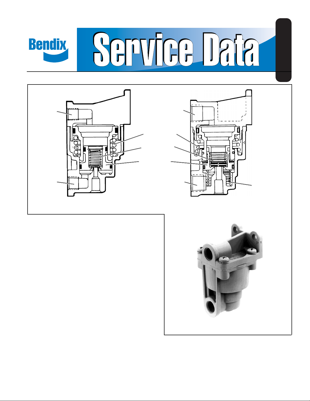
Bendix® LQ-3™ & LQ-4™* Front Axle Ratio Valve
SD-03-951
1/4" NPT
PISTON SPRING
INLET EXHAUST
VALVE SPRING
LOWER PISTON
ASSEMBLY
1/4" NPT
(*THE LQ-4™ VALVE'S OPERATION IS IDENTICAL TO THE LQ-3™ VALVE.
INTERNAL CONFIGURATION IS SLIGHTLY DIFFERENT.)
FIGURE 1 - LQ-3™ AND LQ-4™ FRONT AXLE RATIO VALVE
FUNCTION AND DESCRIPTION
The LQ-3™ and LQ-4™ front axle ratio valve is used on the
front or steering axle of a vehicle to limit the brake application pressure to the actuators during normal service braking.
Limiting application pressure reduces the braking effort at
the foundation brakes on the steering axle. The supply and
delivery ports in both the LQ-3™ and LQ-4™ valves are identified with embossed lettering. The ports in the LQ-3™ valve
are 1/4 inch N.P.T. and in the LQ-4™ valve, 3/8 inch N.P.T.
The exhaust port is not threaded in either valve. T wo mounting holes are provided for 5/16 inch mounting bolts. Note:
When mounted on the vehicle the exhaust port should be
pointed down.
3/8" NPT
3/8" NPT
LQ-4
HOLD OFF
SPRING
™
FRONT AXLE RATIO VALVE*LQ-3™ FRONT AXLE RATIO VALVE
(WHEN REQUIRED)
GENERAL OPERATION
The supply port of the LQ-3™ or LQ-4™ valve is connected to
the delivery port of the service brake valve. The delivery port
of the LQ-3™ valve is connected to the service port of the
front axle relay valve or the adaptive braking modulator. The
LQ-4™ valve may be used to operate brake chambers up to
Type 24 without relay or QR V .
Pressure delivered to the LQ supply port is reduced by 50%
as it passes through the valve and out the delivery port. The
50% reduction occurs only when brake application pressure
LQ-3™ FRONT AXLE RATIO VALVE
EXTERIOR
to the supply port of the LQ is between 0 psi and 40 psi.
Brake applications between 40 psi and 60 psi to the LQ
supply port are reduced by less than 50% and applications
above 60 psi are not reduced at all. An example would be:
65 psi delivered to the supply port results in 65 psi out the
LQ delivery port.
1
Page 2
E-6™/E-7
BRAKE
VALVE
™
BRAKE
CHAMBER
BRAKE
CHAMBER
MODULATOR
OR RELAY
VALVE
BRAKE
CHAMBER
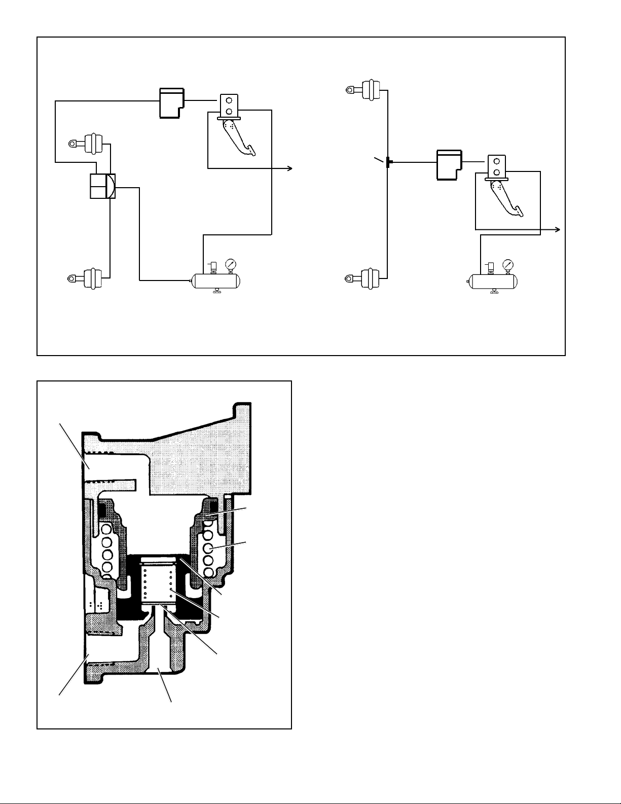
TYPICAL LQ-3™ FRONT AXLE RATIO VALVE INSTALLATION
FIGURE 2 - TYPICAL INSTALLATIONS
SUPPLY
LQ-3
VALVE
™
RESERVOIR
™
E-6™/E-7
BRAKE
TEE
BRAKE
CHAMBER
TYPICAL LQ-4
LQ-4
VALVE
™
FRONT AXLE RATIO VALVE INSTALLATION
VALVE
™
RESERVOIR
Note: The pressures used here are examples only. Both
the LQ-3™ and LQ-4™ valves may have been supplied with
initial hold-off pressures of either 4 psi or 10 psi and equalization pressures of 60 or 65 psi respectively depending
upon the vehicle installation and manufacturer’s specification. The LQ-3™ valve hold-off pressure depends on the
inlet-exhaust valve spring installed. The LQ-4™ valve by
whether or not a hold-off spring is installed under the lower
piston.
OUTER
PISTON
OUTER
PISTON
RETURN
SPRING
INNER PISTON
INLET & EXHAUST
VALVE RETURN
SPRING
INLET & EXHAUST
VALVE
DELIVERY
FIGURE 3 - LQ-3™* BRAKE VALVE APPLICATION: 0-40 PSI
™
(*LQ-4
2
VALVE OPERATION SAME AS LQ-3™ VALVE.)
EXHAUST
OPERA TION — BRAKE APPLICATION OF 40
PSI OR LESS
When a service brake application of less than 40 psi is made,
application air enters the LQ valve supply port and exerts a
force over the surfaces of the outer and inner pistons.
Because of the spring force beneath the outer piston, only
the inner piston moves. The initial delivery of air from the
brake valve forces the inner piston all the way down as shown
in Figure 3. Delivery pressure builds up under the inner
piston as shown in Figure 4 and as explained under
Operation — Balanced.
OPERATION — BALANCED
Air pressure present at the delivery port of the LQ-3™ or
LQ-4™ valve is also present beneath the inner piston. When
the air pressure acting on the underside of the inner piston
is approximately half of the brake valve delivered pressure,
the piston lifts, closing the inlet. The exhaust remains closed.
(See Figure 4.)
Page 3
SUPPLY
SUPPLY
OUTER
PISTON
OUTER
PISTON
RETURN
SPRING
INNER PISTON
INLET & EXHAUST
VALVE RETURN
SPRING
DELIVERY
EXHAUST
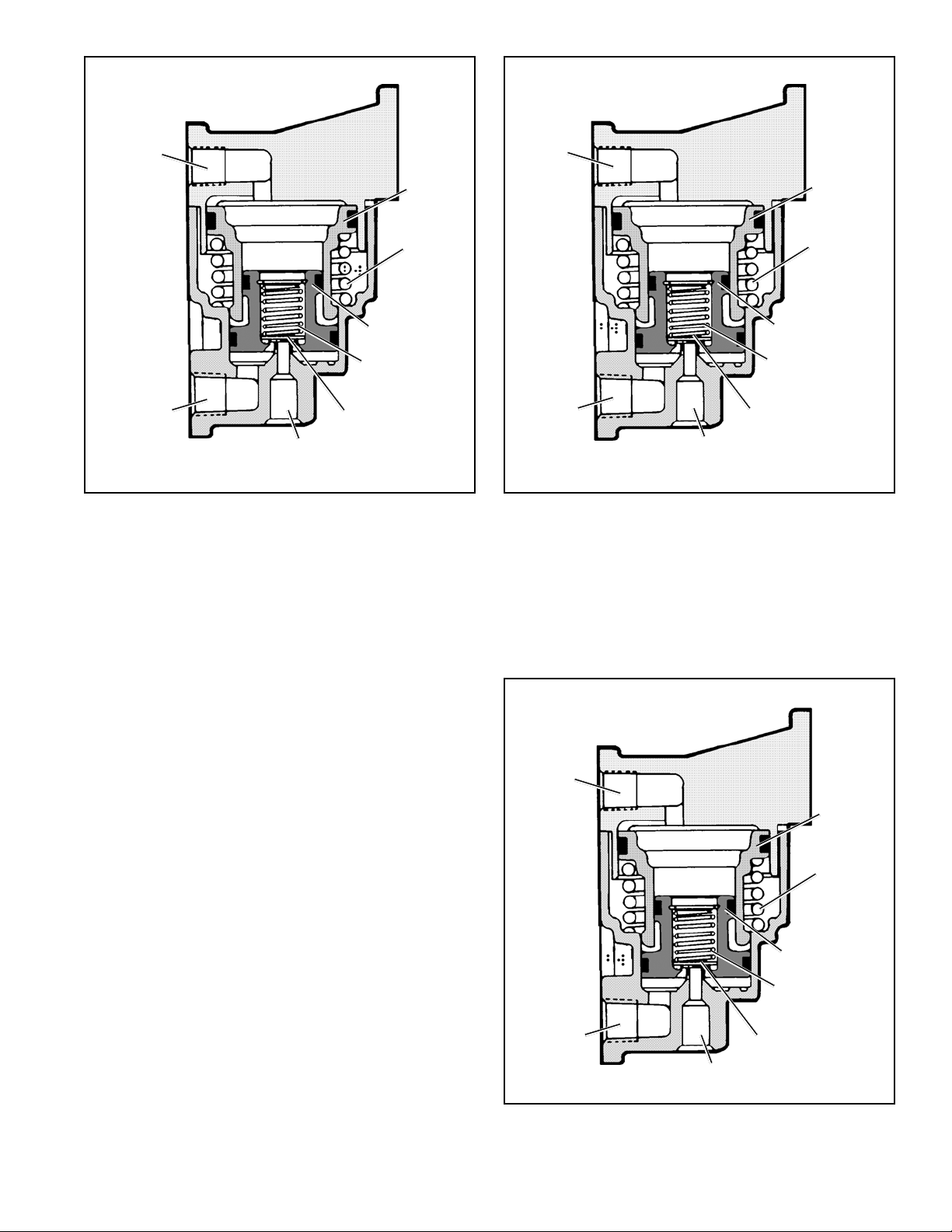
FIGURE 4 - LQ-3
BALANCED BRAKE VALVE APPLICATION AT 40 PSI OR
LESS. (*LQ-4™ VA LVE OPERATION SAME AS LQ-3™ VA LVE.)
™
FRONT AXLE RATIO VALVE*
INLET & EXHAUST
VALVE
Note: The top surface of the inner piston has approximately
one half of the area of the lower surface of the inner piston.
Air pressure acting on the top surface of the inner piston
exerts a force one half as great as the same air pressure
acting on the lower surface. Therefore, to balance the piston, (both inlet and exhaust closed) the pressure beneath
the inner piston may be 1/2 that above it. An example would
be: 30 psi delivered to the supply port and acting on the top
surface of the inner piston would result in approximately 15
psi at the delivery port and acting on the lower surface.
OUTER
PISTON
OUTER
PISTON
RETURN
SPRING
INNER PISTON
INLET & EXHAUST
VALVE RETURN
SPRING
DELIVERY
EXHAUST
FIGURE 5 - LQ-3™ FRONT AXLE RATIO VALVE* EXHAUST.
™
(*LQ-4
VALVE OPERATION SAME AS LQ-3™ VALVE.)
INLET & EXHAUST
VALVE
“catch up” at the rate of 2:1 as supply pressure increases
from 40-60 psi. An example would be: a brake application of
50 psi would result in delivery pressure of 40 psi. For service
applications of 60 psi or greater the LQ valve does not reduce delivery pressure. (See Figure 6.)
OPERATION — EXHAUST
When the service brake application is released, the air above
the inner piston of the LQ valve returns to the brake valve
and is exhausted. The air pressure at the delivery port of the
LQ valve acts on the underside of the inner piston and lifts it,
which unseats the exhaust valve. (See Figure 5.) The delivery volume air exhausts both through the brake valve and
out the exhaust port.
OPERATION — SERVICE BRAKE APPLICATION
40 PSI OR GREATER
When a service brake application of greater than 40 psi is
made, air entering the supply port forces the outer piston
into contact with the inner piston against the resistance of
the outer piston return spring. Both the outer and inner pistons now move as one. Because of the added surface area
of the outer piston, delivery pressure from the LQ valve will
SUPPLY
OUTER
PISTON
OUTER
PISTON
RETURN
SPRING
INNER PISTON
INLET & EXHAUST
VALVE RETURN
SPRING
DELIVERY
EXHAUST
FIGURE 6 - LQ-3™ FRONT AXLE RATIO VALVE* BRAKE
VALVE APPLICATION AT 60 PSI OR GREATER.
(*LQ-4™ VALVE OPERATION SAME AS LQ-3™ VALVE.)
INLET & EXHAUST
VALVE
3
Page 4

INNER
PISTON
SPRING
(9)
INLET
EXHAUST
VALVES
(10)
FIGURE 7 - LQ-4™ FRONT AXLE RATIO VALVE
INNER PISTON (3)
BODY (2)
HOLD OFF
SPRING
(11)
COVER
(1)
O-RING (6)
OUTER
PISTON (4)
O-RING (7)
OUTER
PISTON
SPRING (5)
O-RING (8)
supply line. The 50% reduction will occur while supply
line pressure is between 0 and 40 psi.
4. When the supply line pressure exceeds 40 psi, but is
below 60 psi, observe that the delivery line pressure is
no longer one half and that the delivery line pressure is
“catching up” to supply pressure.
5. When supply pressure exceeds 60 psi note that the
delivery line pressure is approximately equal.
Note: The pressures stated here are examples only.
Various piece numbers of the LQ valves may have
different pressure settings. For information on a specific
installation, consult the vehicle handbook.
LEAKAGE CHECKS
Make and hold a service brake application. Apply a soap
solution to the exhaust port and around the seam between
the cover and the body . Leakage equivalent to a 1" bubble in
5 seconds is permissible.
If the LQ valve does not function as described above or leakage is excessive, it is recommended that it be returned to
the nearest Bendix authorized outlet for a factory remanufactured valve under the Exchange Plan. If this is not possible,
the valve can be repaired with genuine Bendix parts, in which
case the following should prove helpful.
Note: Maintenance kits for the LQ-3™ and LQ-4™ front axle
ratio valves are available from any authorized Bendix outlet.
PREVENTIVE MAINTENANCE
Important: Review the Bendix Warranty Policy before per-
forming any intrusive maintenance procedures. A warranty
may be voided if intrusive maintenance is performed during
the warranty period.
No two vehicles operate under identical conditions, as a
result, maintenance intervals may vary. Experience is a valuable guide in determining the best maintenance interval for
air brake system components. At a minimum, the valve
should be inspected every 6 months or 1500 operating hours,
whichever comes first, for proper operation. Should the valve
not meet the elements of the operational tests noted in this
document, further investigation and service of the valve may
be required.
SERVICE CHECKS
OPERATIONAL CHECKS
1. Install a test gauge or gauge of known accuracy in the
supply and delivery lines of the LQ valve.
2. Build system air pressure to governor cut-out, turn off
engine and apply parking brakes.
3. While making a slowly increasing service brake application, note that the pressure registered on the gauge
installed in the delivery line from the LQ valve is approximately half the pressure registered on the gauge in the
REMOVAL
Apply the vehicle parking brakes. Identify and disconnect
the supply and delivery lines of the LQ valve. Remove the
two mounting bolts securing the LQ valve to the vehicle.
DISASSEMBLY
1. Prior to removing the four Phillips head screws and their
lockwashers which secure the cover to the body , mark
the relationship between the cover and the body .
2. Carefully separate the cover (1) (Figure 7) from the body
(2) and remove the inner (3) and outer pistons (4). (The
cover is under approximately 30 pound load from the
outer piston spring.)
3. Remove the outer piston spring (5).
4. Separate the inner and outer pistons.
5. Remove the o-ring (6) from the outer piston.
6. Remove the large (8) and small (7) diameter o-ring from
the inner piston.
7. (LQ-4™ valve) Remove the inlet exhaust valve spring (9)
and inlet exhaust valve (10) from the inner piston.
Remove the hold-off spring (1 1) if present
8. (LQ-3™ valve — Figure 8) Remove the retaining ring (1),
washer (2), inlet exhaust valve spring (3), and inlet
exhaust valve (4).
4
Page 5

WASHER
(2)
INLET-EXHAUST
VALVE (4)
7. Place the cover over the body in the proper position, as
marked in Step 1 of the Disassembly procedure.
8. Using the four Phillips head screws and lockwashers,
secure the cover to the body. Torque the screws to
50-80 inch pounds.
INLET
EXHAUST
SPRING (3)
RETAINING
RING
(1)
™
FIGURE 8 - LQ-3
PISTON ASSEMBL Y
FRONT AXLE RATIO VALVE INNER
CLEANING AND INSPECTION
1. Wash all metal parts in mineral spirits and dry them.
2. Inspect all parts for excessive wear or deterioration.
3. Inspect the valve seat for nicks or burrs.
4. Check the spring for cracks or corrosion.
5. Replace all rubber parts and any part not found to be
serviceable during inspection, using only genuine Bendix
replacement parts.
ASSEMBLY
Prior to reassembling the LQ front axle ratio valve, lubricate
all o-rings, o-ring grooves, piston bores and metal moving
surfaces with Bendix silicone lubricant piece number 291 126
(Dow Corning 650-M).
1. (LQ-3™ valve — Figure 8) Place the inlet and exhaust
valve (4), valve spring (3), and washer (2) in the inner
piston. Install the retaining ring (1) in the piston, making
certain it is completely seated in its groove.
(LQ-4™ valve — Figure 7) Place the inlet and exhaust
valve (10) and spring (9) in the inner piston (3). The spring
must be carefully located under the shoulder in the
inner piston.
2. Install the large (8) and small (7) diameter o-rings in
their grooves on the inner piston.
3. Install the o-ring (6) on the outer piston.
4. Insert the inner piston into the bore of the outer piston.
Note: See Figure 7 for proper inner and outer piston
configuration after assembly .
5. Place the outer piston spring (5) in the valve body and
the hold-off spring (1 1) if used.
6. Install the inner and outer piston assembly in the body
through the spring (see Figure 7).
TESTING THE REBUILT LQ-3™ AND LQ-4
™
FRONT AXLE RATIO V AL VE
Test the rebuilt LQ-3™ or LQ-4™ front axle ratio valve by
performing the operational and leakage tests outlined in the
Service Checks section of this manual.
WARNING! PLEASE READ AND FOLLOW
THESE INSTRUCTIONS TO AVOID
PERSONAL INJURY OR DEATH:
When working on or around a vehicle, the following
general precautions should be observed at all times.
1. Park the vehicle on a level surface, apply the
parking brakes, and always block the wheels.
Always wear safety glasses.
2. Stop the engine and remove ignition key when
working under or around the vehicle. When
working in the engine compartment, the engine
should be shut off and the ignition key should be
removed. Where circumstances require that the
engine be in operation,
be used to prevent personal injury resulting from
contact with moving, rotating, leaking, heated or
electrically charged components.
3. Do not attempt to install, remove, disassemble or
assemble a component until you have read and
thoroughly understand the recommended
procedures. Use only the proper tools and observe
all precautions pertaining to use of those tools.
4. If the work is being performed on the vehicle’s air
brake system, or any auxiliary pressurized air
systems, make certain to drain the air pressure from
all reservoirs before beginning ANY work on the
vehicle. If the vehicle is equipped with an AD-IS
air dryer system or a dryer reservoir module, be
sure to drain the purge reservoir.
5. Following the vehicle manufacturer’s
recommended procedures, deactivate the electrical
system in a manner that safely removes all
electrical power from the vehicle.
6. Never exceed manufacturer’s recommended
pressures.
7. Never connect or disconnect a hose or line
containing pressure; it may whip. Never remove a
component or plug unless you are certain all
system pressure has been depleted.
8. Use only genuine Bendix® replacement parts,
components and kits. Replacement hardware,
tubing, hose, fittings, etc. must be of equivalent
size, type and strength as original equipment and
be designed specifically for such applications and
systems.
EXTREME CAUTION should
™
5
Page 6

9. Components with stripped threads or damaged
parts should be replaced rather than repaired. Do
not attempt repairs requiring machining or welding
unless specifically stated and approved by the
vehicle and component manufacturer.
10. Prior to returning the vehicle to service, make
certain all components and systems are restored to
their proper operating condition.
6
Page 7

7
Page 8

8
BW1573 © 2004 Bendix Commercial Vehicle Systems LLC All rights reserved. 4/2004 Printed in U.S.A.
 Loading...