

Page 1
®
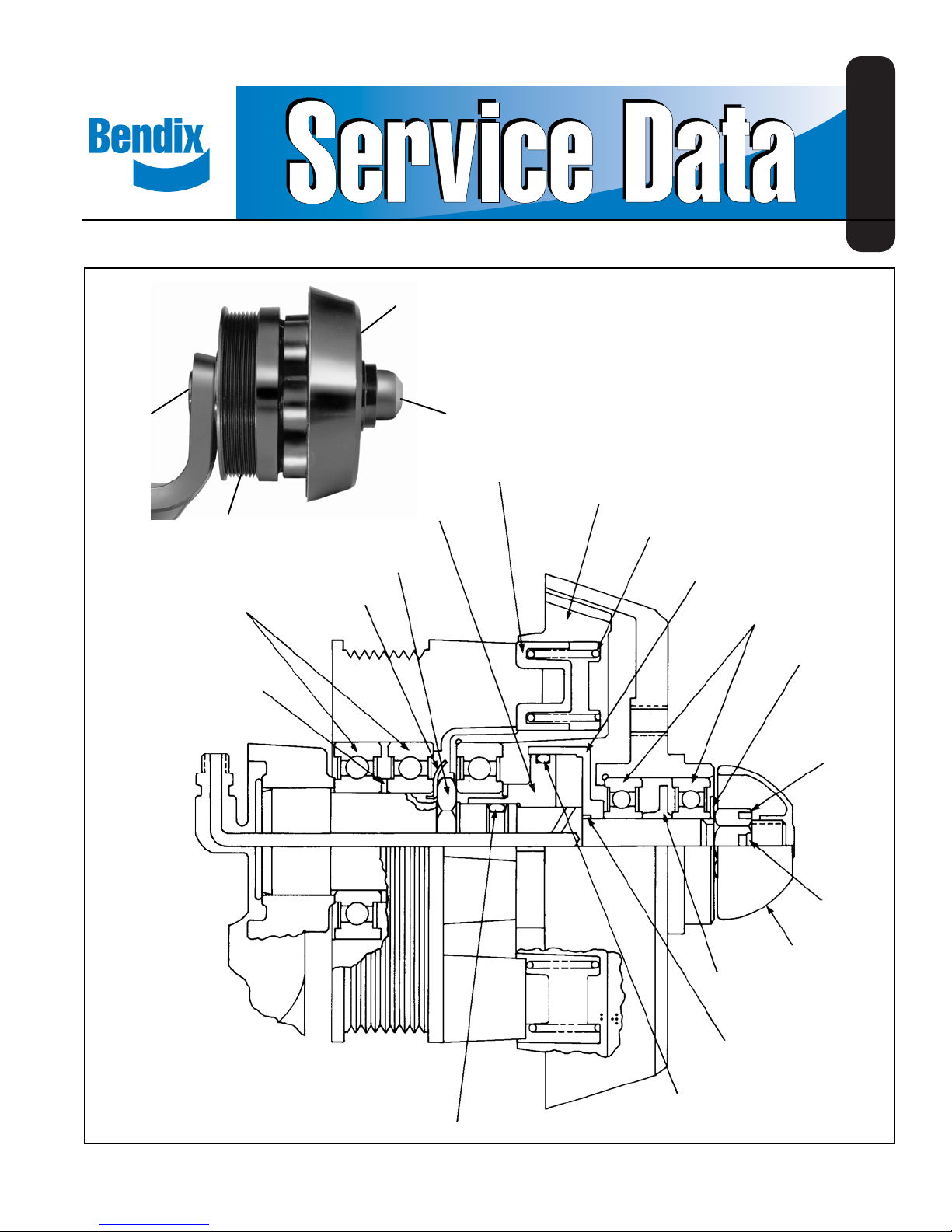
Bendix® FD-L™ Fan Clutch
SD-09-8505
FAN HUB
BRACKET
PULLEY
BEARINGS
SPACER
PISTON COMPLETE
HEX NUT
LOCKWASHER
DUST CAP
ISOLATOR
PRESSURE PLATE
SPRING
PISTON HOUSING
BEARINGS
WASHER
HEX NUT
FIGURE 1
COTTER PIN
CAP
SPACER
O-RING
O-RING
O-RING
1
Page 2
The FD-L™ fan clutch is designed for mid-range diesel engine
applications and can withstand maximum fan torque of 750
inch pounds and a fan weight not to exceed 15 pounds. It
cannot be used to replace heavy duty clutches or hubs that
do not meet the above stated specifications.
DESCRIPTION
The Bendix® FD-L™ fan clutch is an air operated
thermostatically controlled clutch for the engine cooling fan.
Its purpose is to maintain engine temperature by engaging
or disengaging the cooling fan, thereby , providing better fuel
economy , greater engine efficiency , faster warm-ups and a
quieter vehicle.
The FD-L™ fan clutch is produced in several different models
to accommodate the variety of installation requirements
resulting from the many engine, vehicle and accessory
combinations. Its fail-safe design prevents overheating in
the event of air loss for any cause.
OPERATION
GENERAL
The FD-L™ fan clutch replaces the standard fan hubs on the
engine of mid-range diesel vehicles. It is controlled by a
temperature sensitive air valve. (See Figure 4). The same
type of valves used to control radiator shutters are used to
control the FD-L™ fan clutch. Installed in the engine block,
the thermo-pneumatic control valve directly senses coolant
temperature. Provided coolant temperature remains below
the setting of the valve, air passes through it to disengage
the fan clutch. When coolant temperature rises to the valve
setting, the valve closes and exhausts air pressure from the
fan clutch which engages the fan.
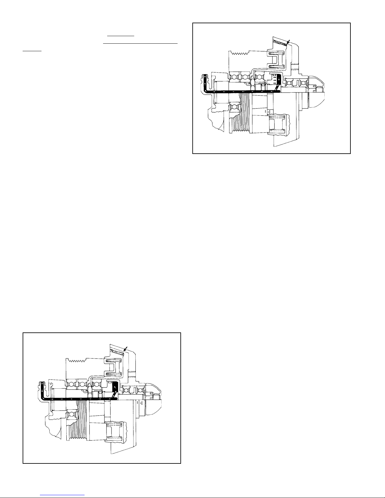
FAN ENGAGED
PISTON MOVES
FORWARD AS AIR IS
EXHAUSTED
FIGURE 3
DISENGAGED
When the vehicle is started with a cold engine the thermopneumatic control valve is open. As brake system air
pressure is built up, air passes through the control valve to
the fan clutch. Air enters the inlet port in the bracket of the
fan clutch and travels through the drilled passage in the
shaft to fill the piston cavity. When air in the piston cavity
reaches a pressure of 75-80 psi, the piston slides on the
shaft moving the pressure plate assembly to the disengaged
position. In this position the clutch lining is out of contact
with the fan plate and the fan is no longer driven by the
engine (see Figure 2).
ENGAGED
Depending upon optional equipment installed on the vehicle
such as radiator shutters and radiator mounted air
conditioning condenser, dif ferent piping arrangements are
necessary. These will be explained in the paragraph on
control systems.
FAN DISENGAGED
FIGURE 2
2
As the engine coolant rises in temperature, the engine
thermostat opens to circulate radiator coolant through the
engine. When the engine coolant temperature reaches the
setting of the control valve, the valve exhausts air from the
piston cavity. The fan clutch springs force the pressure
plate forward until the lining contacts the fan plate. The fan
is engaged and is driven by the engine (see Figure 3).
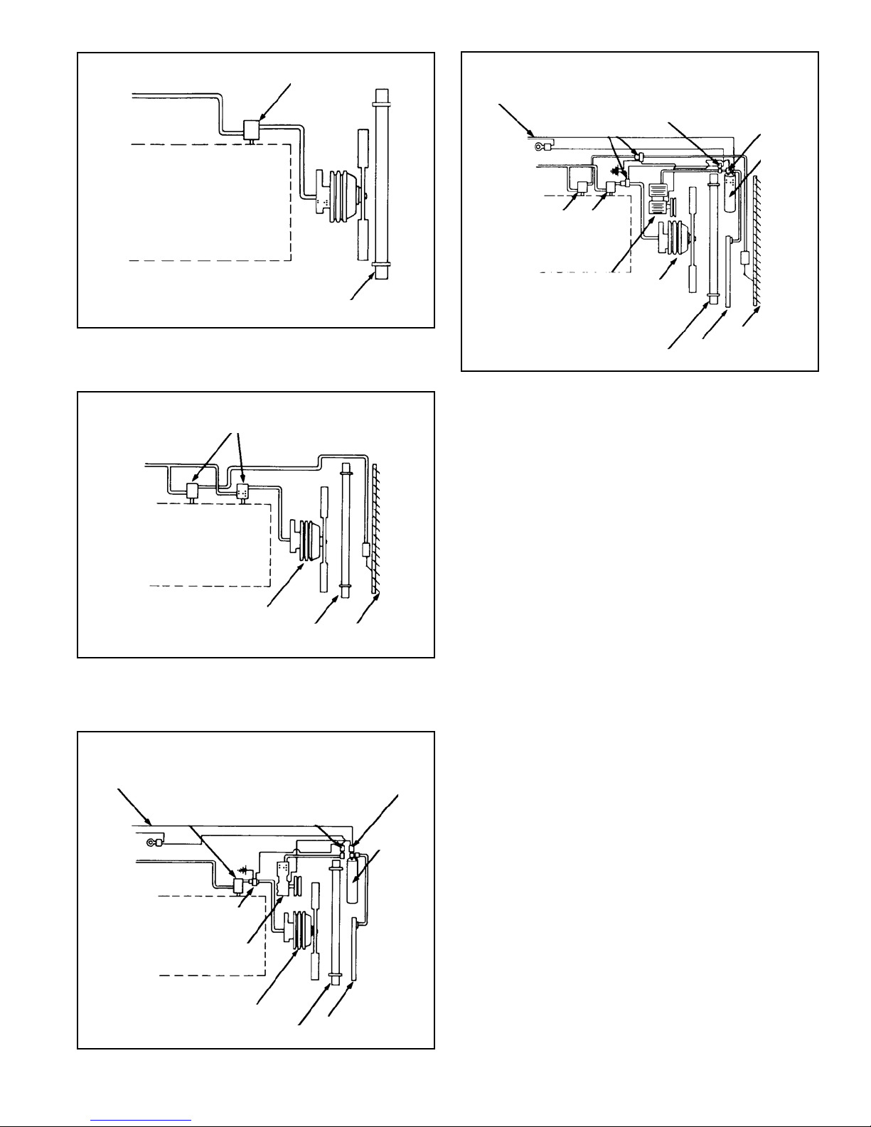
CONTROL SYSTEMS
The fan clutch, in addition to its primary function of operating
the fan as needed to maintain the cooling liquid within a
certain temperature range, must be coordinated with other
devices when installed on the vehicle; these are radiator
shutters and radiator mounted condenser for air
conditioning. Four basic configurations are possible as
follows:
FIGURE 4. F AN CLUTCH ONL Y
FIGURE 5. F AN CLUTCH WITH SHUTTERS
FIGURE 6. F AN CLUTCH WITH RADIATOR MOUNTED
CONDITIONING CONDENSER
FIGURE 7. FAN CLUTCH, SHUTTERS AND CONDENSER
Page 3
BLOCK
THERMO-PNEUMATIC
VALVE
FAN
CLUTCH
AIR
CONDITIONING
SIGNAL
THERMO-PNEUMATIC
SOLENOID VALVES
(NORMALLY OPEN)
VALVE
BLOCK
FAN
OVERRIDE
SWITCH
AIR
CONDITIONER
OVERRIDE
SWITCH
RECEIVER
DRYER
FIGURE 4
FIGURE 5
AIR
CONDITIONING
SIGNAL
THERMO-PNEUMATIC
BLOCK
THERMO-PNEUMATIC
VALVES
BLOCK
FAN
CLUTCH
VALVE
SOLENOID VALVE
AIR COND.
COMPRESSOR
FAN
CLUTCH
RADIATOR
FAN
OVERRIDE
SWITCH
RADIATOR
RADIATOR
SHUTTER
CONDITIONING
OVERRIDE
CONDENSER
AIR
SWITCH
RECEIVER
DRYER
AIR COND. COMPRESSOR
FIGURE 7
FAN
CLUTCH
RADIATOR
CONDENSER
SHUTTER
The objective in the case of Figure 5 is to not engage the fan
until the shutters are fully open. The thermo-pneumatic control
valve should therefore be calibrated to release the air from
the fan clutch when the coolant temperature is at least 10°F
higher than the full-open temperature of the shutter.
In the case of Figure 6, the fan must be controlled to perform
the supplementary function of pulling cooling air through
the air conditioning condenser when required, although the
engine coolant may be below the fan cut-in temperature.
This is most likely to occur at high ambient temperatures
and low road speed or idling. If the condenser is
inadequately cooled, the air conditioning system will start
to build up a higher than normal pressure. Therefore, a
pressure switch is connected into the air conditioning
compressor discharge line, as shown in Figure 6. When
this pressure switch senses a higher than normal pressure
in the air conditioning system (approximately 250 psi), it
closes an electrical circuit which in turn energizes a solenoid
operated air supply valve which exhausts the air supply for
the fan control, causing the fan to engage.
Most vehicles also have an additional dual function pressure
switch connected in series with the air conditioner clutch.
This switch is normally open, closes at approximately 30
psi and opens again at approximately 400 psi. Its purpose
is to prevent operation of the air conditioning compressor if
the refrigerant is lost or to shut off the compressor if the
system pressure reaches a dangerously high pressure
(approximately 400 psi). This switch does not normally have
anything to do with fan operation; however, it is sometimes
combined with the previously mentioned override switch.
FIGURE 6
3
Page 4

Figure 7 depicts a combination of shutters, fan clutch and
air conditioning. This combination requires the two thermopneumatic controls for fan and shutters, as well as the
electro-pneumatic override for the air conditioning. With this
combination the same requirements for fan control apply as
in Figure 5 and 6 with the additional requirement that the
shutters should be controlled in such a manner that they
always open whenever the air conditioning compressor
operates.
A variation of this combination consists of a two section
shutter with one section in front of the condenser and other
in front of the remaining portion of the radiator. In this
combination only the section in front of the condenser needs
to open when the air conditioner engages.
PREVENTIVE MAINTENANCE
There is no need for periodic maintenance; however, the
following service checks should be made to ensure proper
function of the fan clutch.
GENERAL
The condition of the two fan plate ball bearings should be
checked at regular intervals to ensure proper operation of
the FD-L™ fan clutch. The procedure presented here is
intended to check excessive bearing play by measuring
lateral movement of the fan plate relative to the edge of the
pulley or a scribed line on the lining surface, when air is
applied.
FAN PLATE
DUST SHIELD
PULLEY
THE TOTAL CHANGE IN THIS
DIMENSION FROM ITS
NARROWEST TO WIDEST
MEASUREMENT SHOULD
NOT BE 1/16” OR GREATER
FIGURE 8
CHECKING PROCEDURES
1. Park the vehicle on a level surface and block the wheels.
2. Shut off the engine and apply a minimum of 85 psi to
the fan clutch to disengage it. NOTE: If air brake system
pressure is above 85 psi and the engine is cool, the
FD-L™ fan clutch will be disengaged. Disengagement is
confirmed by noting that the fan can be rotated freely by
hand. DO NOT PERFORM THIS CHECK WITH ENGINE
RUNNING.
3. With the engine off and the FD-L™ fan clutch disengaged,
grasp the tip of one blade using only the thumb and
index finger. (Refer to Figure 8). Using a moderate force,
rock the fan blade back and forth toward the radiator
and measure the total movement of the fan plate relative
to the edge of the pulley. Replace or repair the fan
clutch if the total movement of the fan plate is 1/16" or
greater.
LINE HAUL VEHICLES
Every 50,000 miles, 1,800 hours, or every six months,
whichever occurs first, perform the service checks out lined
in this manual.
CITY DELIVERY
Every 15,000 miles, 300 hours or two months, whichever
occurs first, perform the service checks outlined in this
manual.
SERVICE CHECKS
Before performing the operational and leakage checks,
apply the vehicle parking brakes or chock the wheels.
OPERATIONAL
1. With the engine cold, the ignition off and at lease 85 psi
air pressure in the brake system, note that the fan is
disengaged from the pulley and can be turned by hand.
If the fan can be turned, proceed to Step #2. If it cannot
be turned:
A. Drain all reservoirs and disconnect the air control
line leading to the fan clutch and apply at least 85
psi shop air pressure to the fan clutch.
B. If the fan cannot be turned, the clutch is defective
and must be repaired or replaced (see appropriate
section of this manual).
C. If the fan can now be turned, check the air lines
leading to and from the thermostatic control valve for
“kinks” or obstructions, and check the control valve
itself according to the manufacturer’s instructions.
4
Page 5

2. After performing check #1, drain all air pressure from the
brake system. Note that the fan is now engaged and
cannot be turned by hand. If it cannot be turned, proceed
to test #3. If it can be turned, the clutch is defective and
must be repaired or replaced.
3. Check the operation of the thermostatic control valve by
running the engine up to operating temperature. Note
that the fan clutch engages when engine temperature
rises to normal or above and disengages after fan
cooling is accomplished. Normal engagement time
should not exceed two minutes. If engagement time does
not exceed two minutes, proceed to check #4. If
engagement time does exceed two minutes:
A. If this test is being performed for the first time after
installation of the fan clutch, recheck the setting of
the thermostatic control valve and compare it with
the setting of the engine coolant thermostat or in the
case of vehicles with radiator shutters, with the
setting of the shutter control. The fan clutch control
should always be 10°F higher than the highest setting.
B. If the fan clutch installation has successfully passed
this test before, but does not do so now, the
thermostatic control valve or thermostat are defective
and should be replaced.
LEAKAGE CHECKS
In order to check for air leakage past the only two sliding
o-rings in the FD-L™ fan clutch, it is necessary to disconnect
the single air control line.
Check for leakage by connecting a 90 cu. in. reservoir
(Bendix part number 225000) with a gauge installed to the
control port of the fan clutch. After filling the 90 cu. in.
reservoir with 100 psi, allow the pressure to stabilized and
observe the time required for the reservoir pressure to drop
to 90 psi. If the time required is less than 1 minute, leakage
is excessive and repair or replacement is necessary .
WARNING! PLEASE READ AND FOLLOW
THESE INSTRUCTIONS TO AVOID
PERSONAL INJURY OR DEATH:
When working on or around a vehicle, the following
general precautions should be observed at all times.
1. Park the vehicle on a level surface, apply the
parking brakes, and always block the wheels.
Always wear safety glasses.
2. Stop the engine and remove ignition key when
working under or around the vehicle. When
working in the engine compartment, the engine
should be shut off and the ignition key should be
removed. Where circumstances require that the
engine be in operation, EXTREME CAUTION should
be used to prevent personal injury resulting from
contact with moving, rotating, leaking, heated or
electrically charged components.
3. Do not attempt to install, remove, disassemble or
assemble a component until you have read and
thoroughly understand the recommended
procedures. Use only the proper tools and observe
all precautions pertaining to use of those tools.
4. If the work is being performed on the vehicle’s air
brake system, or any auxiliary pressurized air
systems, make certain to drain the air pressure from
all reservoirs before beginning ANY work on the
vehicle. If the vehicle is equipped with an AD-IS
air dryer system or a dryer reservoir module, be
sure to drain the purge reservoir.
5. Following the vehicle manufacturer’s
recommended procedures, deactivate the electrical
system in a manner that safely removes all
electrical power from the vehicle.
6. Never exceed manufacturer’s recommended
pressures.
7. Never connect or disconnect a hose or line
containing pressure; it may whip. Never remove a
component or plug unless you are certain all
system pressure has been depleted.
8. Use only genuine Bendix® replacement parts,
components and kits. Replacement hardware,
tubing, hose, fittings, etc. must be of equivalent
size, type and strength as original equipment and
be designed specifically for such applications and
systems.
9. Components with stripped threads or damaged
parts should be replaced rather than repaired. Do
not attempt repairs requiring machining or welding
unless specifically stated and approved by the
vehicle and component manufacturer.
10. Prior to returning the vehicle to service, make
certain all components and systems are restored
to their proper operating condition.
REMOVAL
It is recommended that the FD-L™ fan clutch be removed
from the vehicle for service even though it is possible on
some installations to install kits 106733 and 106732 without
clutch removal.
1. Secure the vehicle on a level surface by means other
than the brakes.
2. Drain ALL reservoirs to 0 psi (0 kPa) air pressure.
3. Disconnect the air line from the fan clutch.
4. Remove the six cap screws and lockwashers that attach
the vehicle’s fan to the fan plate of the FD-L™ fan clutch.
™
5
Page 6

15
7
8
17
16
6
14
13
11
12
5
18
Key Description Qty.
1 Coffer Pin 1
2 O-Ring
3 O-Ring
4 O-Ring
5 Cap
6 Pressure Plate
Complete 1
FIGURE 9
Key Description Qty.
7 Spring 6
8 Isolator 3
9 Washer 1
10 Spacer 1
1 1 Ball Bearing 2
12 Hex Nut 1
5. Remove the fan. NOTE: Remove and retain any spacers
that may be installed between fan and fan plate
assembly.
6. Loosen, remove and retain the vehicle’s fan belts.
7. Remove the attaching hardware from the fan clutch
mounting bracket and remove the fan clutch from the
vehicle.
4
3
2
Key Description Qty.
13 Piston Housing 1
14 Piston Complete 1
15 Bearing 2
16 Hex Nut 1
17 Lockwasher 1
18 Spacer 1
10
9
1
7. Disengage the lock tabs on lockwasher (17) and using a
1-9/16” socket, remove hex nut (16) and the lockwasher
(17).
NOTE: To fabricate a tool to remove the 1-9/16” hex nut,
take two deep sockets and cut the end out of one
and weld the remaining length onto the bottom of
the other socket to make it approximately double
the original length.
DISASSEMBLY (REFER TO FIGURE 9)
1. Remove dust cap (5). Remove the cotter pin (1) from
the locknut (12). Remove the locknut (12) and washer
(9).
2. Remove the fan plate assembly and set aside.
3. Slide the piston housing (13) and piston (14) off the
shaft.
4. Separate the piston (14) from the piston housing (13)
and remove the o-ring (3).
5. Remove the o-rings (2 & 4) from the shaft.
6. Remove the pressure plate (6) and the six springs (7).
6
PULLEY DISASSEMBLY
1. Support the backside of the pulley so that the shaft
bracket assembly can be pressed down far enough to
remove the pulley assembly. Since the bearings are
originally installed with Loctite between the shaft and
bearings, a force as high as 5000 lbs. may be required
to remove the pulley assembly. The bearings will be
damaged after this point of disassembly and must be
replaced.
Page 7

2. Support the pulley on the bracket side in such a manner
that the support will not interfere with the removal of the
roller bearing (15). Use a pressing tool of adequate
diameter to engage the outer race of the ball bearing.
Press out both ball bearings (15) and the spacer (18).
The bearings will be damaged after this point of
disassembly and must be replaced.
3. Remove the three isolators (8) from the bosses of the
pulley . They may require turning and at the same pulling
until they disengage from their seats.
F AN PLA TE DISASSEMBL Y
1. Support the fan mounting surface of the fan plate
assembly making certain sufficient space is left beneath
to permit the ball bearings(1 1) to be pressed out. Use a
pressing tool of adequate diameter to contact the outer
race of the ball bearing, press out both ball bearings
(1 1) and the spacer (10). The bearing must be replaced
once removed.
CLEAN & INSPECT
1. Prior to assembly , wash all metal parts thoroughly using
a quality commercial solvent (such as mineral spirits).
2. Inspect all component parts for wear or damage and
replace any parts that fail this visual inspection.
ASSEMBL Y (REFER TO FIGURE 9)
PULLEY ASSEMBL Y
1. Support the pulley drive end down and using the same
pressing tool as used in the disassembly procedure,
press one of the two ball bearings (15) into the pulley
until it contacts the lip on the pulley housing. (Do not
use a force greater than 1,100 lbs.)
2. Install the spacer (18) into the housing making it as
concentric as possible to the inner race of the bearing
installed in S tep 1.
3. Install the second ball bearing (15) into the housing and
using the pressing tool, press until contact has been
made on the spacer. (Do not use a force greater than
1,100 lbs.) Do not continue pressing the bearing once
the inner race has touched the spacer or severe damage
to the bearings may result. As a check af ter assembly,
the bearing spacer should be in contact with the inner
races of each ball bearing but able to be moved by a
finger load.
4. Install the three isolators (8) onto their seats on the pulley
making certain they are fully seated.
ASSEMBLY OF PULLEY ONTO THE BRACKET AND
SHAFT
1. Support the bracket with the shaft pointing up. Apply
one band of Loctite RC609 around the shaft at the location
of inner races of the bearings (15) in the pulley . Also put
a band of the Loctite on the inner races of the bearings
(15). NOTE: Parts MUST BE free of oil and grease for
Loctite to properly bond.
2. Slide the pulley onto the shaft, making sure the bottom
bearings inner race contacts the bracket.
3. Place lockwasher (17) on the shaft engaging the I.D.
tab in the slot in the shaft and install hexnut (16) using
the same tool as Step 7 of “Disassembly .” Torque hexnut
to 80-130 ft. lbs. until two of the tangs of the lockwashers
(17) can be bent up against the flats of the locknut.
Never back the torque off to align parts. Allow 24 hours
for complete curing of the Loctite to take affect.
ASSEMBL Y OF F AN PLATE
1. Place the fan plate face up on a level surface and with
the pressing tool used in disassembly procedure, press
one of the ball bearings (11) into the housing until it
contacts the lip of the bore. (Do not use a force greater
than 700 lbs)
2. Install spacer(10) into the bore of the fan plate (as
illustrated in Figure 1) concentric with the inner race of
the ball bearing previously installed. (NOTE: Flanged
end of spacer (10) should be toward the forward nose
of the fan plate.)
3. Install the second ball bearing (11) into the bore of the
fan plate and utilizing the pressing tool used in Step 1,
press the ball bearing until it contacts the spacer (10).
(Do not use a force greater than 700 lbs.) Do not
continue pressing the bearing once the inner race has
touched the spacer, severe damage to the bearings
may result. As a check after assembly, the bearing
spacer should be in contact with the inner races of
each ball bearing but able to be moved by a finger load.
FINAL ASSEMBL Y
1. Support the bracket, shaft and pulley assembly with the
shaft pointing up.
2. Install the six springs (7) on the pulley. Three into the
isolators (8) and three onto the bosses provided. NOTE:
The isolators must be equally spaced around the
circumference of the pulley (every other spring).
3. Apply a thin film of silicone lubricant BW-665M to the
three o-rings (2-3-4). Install o-ring (2 & 4) onto the shaft
and o-ring (3) into the groove of the piston (14).
4. Install the pressure plate (6) on the pulley assembly
making sure the bosses on the underside of the plate
mate with the O.D. of the six springs (7) previously
installed on the pulley assembly .
5. Lubricate the I.D. of the piston housing (13) with the
same lubricant used on the o-rings in Step 3. Inst all the
piston (4) (with o-ring (3) in place) into the piston housing.
Install the piston and housing assembly onto the shaft,
making sure the flats on the I.D. of the piston mate with
the flats on the shaft.
7
Page 8

WARNING: FAILURE T O PROPERLY MA TCH THE FLATS
OF THE PISTON TO THE FLAT OF THE SHAFT WILL
RESUL T IN SEVERE DAMAGE TO THE UNIT .
6. Place the fan plate assembly onto the shaft, the washer
(9) and retain with locknut (12). Torque to 90-100 ft.
lbs.
7. Install cotter pin (1) and bend to hold in place. Install
dust cap (5). NOTE: Never back torque off to align the
cotter pin. If necessary increase torque slightly until
slots in locknut and hole in shaft are in line.
TEST
1. With no air pressure applied, the torque required to rotate
the clutch must not exceed 150 in. oz.
2. With 75-80 psi applied, the fan plate must separate from
the pulley and rotate freely .
3. Perform the leakage checks outlined in the manual.
INSTALLATION
1. Attach fan clutch unit to vehicle by installing cap nuts
and lockwashers through mounting bracket holes into
mating holes in engine bracket.
2. Reconnect air line to unit.
3. Adjust fan belts per vehicle manufacturer’s
recommendation.
4. Replace fan on fan plate with six cap screws and
lockwashers. T orque to 300-360 inch pounds. (Be sure
to install any spacers that were removed during
disassembly .)
5. Perform service checks as previously outlined.
RETROFIT INSTALLATION INFORMATION
To determine which fan clutch piece number should be
purchased when retrofitting existing equipment, consult the
nearest authorized Bendix distributor for assistance.
Complete installation instruction and piping diagrams are
packed with each FD-L
It is recommended that only cooling fans approved by the
vehicle or fan manufacturer be installed on the FD-L™ fan
clutch.
Maximum weight of fan blade assembly is 15 lbs.
Maximum thickness of spacers between fan and hub plate
is 1-1/2”.
™
fan clutch.
BW1603 © 2004 Bendix Commercial Vehicle Systems LLC All rights reserved. 4/2004 Printed in U.S.A.
8
 Loading...