

Page 1

®
Bendix® FD-2™ Clutch Type Fan Drive
SD-09-8503
FIGURE 1
SHAFT
BRACKET
AIR INLET
PULLEY
PRESSURE PLATEBEARINGS
DRIVE PIN
FAN HUB
RETURN SPRING
PISTON HOUSING
PISTON
BEARINGS
LOCK
NUT
DUST
CAP
FIGURE 2
DESCRIPTION
The Bendix® FD-2™ fan clutch is an air operated thermostat
controlled clutch for the engine cooling fan. Its purpose is
to maintain engine temperature by engaging or disengaging
the cooling fan, thereby providing better fuel economy,
greater engine efficiency, faster warm-ups, and a quieter
vehicle.
The FD-2™ fan clutch is produced in several different models
to accommodate the variety of installation requirements
resulting from the many engine, vehicle and accessory
combinations. Its fail-safe design prevents overheating in
the event of air loss for any cause.
OPERATION
GENERAL
The FD-2™ fan clutch replaces the standard fan hubs on the
engine and interchanges with other Bendix and competitive
fan clutches. It is controlled by a temperature sensitive air
valve (see Figure 5). The same valves used to control radiator
shutters are used to control the FD-2™ fan clutch. Installed
in the engine block, the control valve directly senses coolant
temperature. Provided coolant temperature remains below
the setting of the valve, air passes through it to disengage
the fan clutch. When coolant temperature rises to the valve
setting, the valve closes and exhausts air pressure from the
fan clutch which engages the fan.
1
Page 2
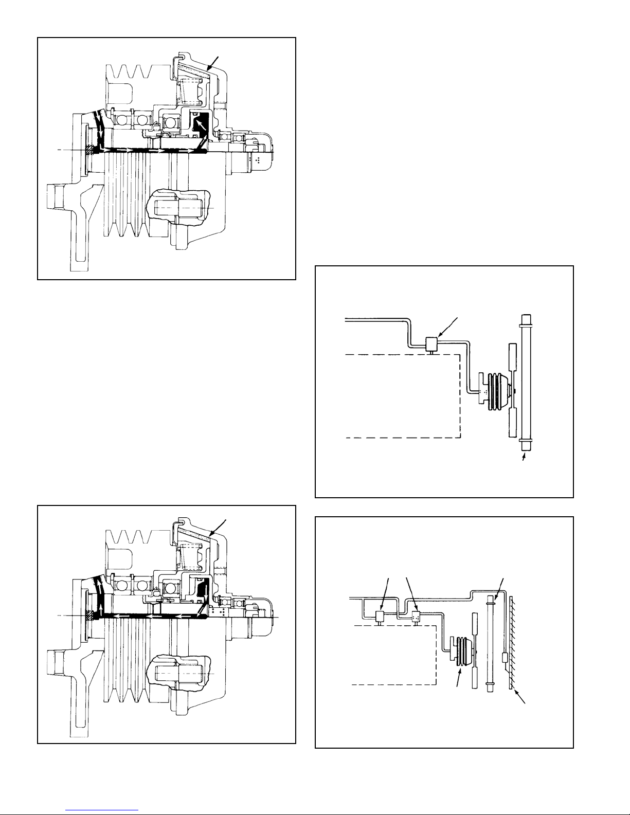
FAN DISENGAGED
FIGURE 3
Depending upon optional equipment installed on the vehicle
such as radiator shutters and radiator mounted air
conditioning condenser, dif ferent piping arrangements are
necessary. These will be explained in the paragraph on
control systems.
shaft to fill the piston cavity. When air in the piston cavity
reaches a pressure of 70-75 psi, the piston slides on the
shaft moving the pressure plate assembly to the disengaged
position. In this position the clutch lining is out of contact
with the fan plate and the fan is no longer driven by the
engine (see Figure 3).
ENGAGED
As the engine coolant rises in temperature, the engine
thermostat opens to circulate radiator coolant through the
engine. When the engine coolant temperature reaches the
setting of the control valve, the valve exhausts air from the
piston cavity. The fan clutch springs force the piston and
pressure plate forward on the shaft. When the lining
contacts the fan plate, the fan is engaged and is driven by
the engine (see Figure 4).
THERMO-PNEUMATIC
VALVE
DISENGAGED
When the vehicle is started with a cold engine the thermopneumatic control valve is open. As brake system air
pressure is built up, air passes through the control valve to
the fan clutch. Air enters the inlet port in the bracket of the
fan clutch and travels through the drilled passage in the
FAN ENGAGED
FIGURE 5
BLOCK
THERMO-PNEUMATIC
VALVES
BLOCK
FAN
CLUTCH
FAN
CLUTCH
RADIATOR
RADIATOR
SHUTTER
FIGURE 4
2
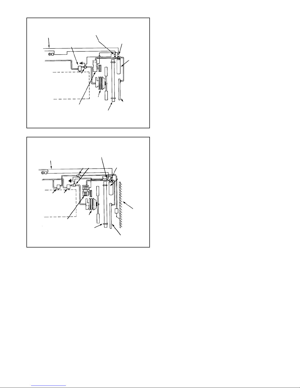
FIGURE 6
Page 3
AIR
CONDITIONING
SIGNAL
OVERRIDE
THERMO-PNEUMATIC
VALVE
FAN
SWITCH
AIR
CONDITIONING
OVERRIDE
SWITCH
RECEIVER
DRYER
The objective in the case of Figure 5 is to not engage the fan
until the engine thermostat is fully open. The thermopneumatic control valve should therefore be calibrated to
release the air from the fan clutch when the coolant
temperature is at least 10°F . higher than the shutter opening
point. If the shutters are the modulating type, the fan
engagement should be at least 10°F . higher than the full-open
temperature of the shutter.
SOLENOID
VALVE
BLOCK
FAN
FIGURE 7
AIR
CONDITIONING
SIGNAL
IGNITION
THERMO-PNEUMATIC
VALVES
BLOCK
AIR COND.
COMPRESSOR
FIGURE 8
AIR COND.
COMPRESSOR
SOLENOID VALVE
(NORMALLY OPEN)
FAN
CLUTCH
RADIATOR
CLUTCH
RADIATOR
FAN
OVERRIDE
SWITCH
CONDENSER
AIR
CONDITIONING
OVERRIDE
SWITCH
RECEIVER
DRYER
SHUTTER
CONDENSER
CONTROL SYSTEMS
The fan clutch, in addition to its primary function of operating
the fan as needed to maintain the cooling liquid within a
certain temperature range, must be coordinated with other
devices when installed on the vehicle.
These are radiator shutters and radiator mounted condenser
for air conditioning. Four basic configurations are possible
as follows:
Figure 5. Fan Clutch only
Figure 6. Fan Clutch with shutters
Figure 7. Fan Clutch with radiator mounted air
conditioning condenser
Figure 8. Fan Clutch, shutters and condenser
In the case of Figure 7 the fan must be controlled to perform
the supplementary function of pulling cooling air through the
air conditioning condenser when required, although the engine
coolant may be below the fan cut-in temperature. This is
most likely to occur at high ambient temperatures and low
road speed or idling. If the condenser is inadequately cooled,
the air conditioning system will start to build up a higher
than normal pressure. Therefore, a pressure switch is
connected into the air conditioning compressor discharge
line (as shown in Figure 7). When this pressure switch senses
a higher than normal pressure in the air conditioning system
(approximately 250 psi), it closes an electrical circuit which
in turn energizes a solenoid operated air supply valve which
exhausts the air supply for the fan control, causing the fan
to engage. Most vehicles also have an additional dual function
pressure switch connected in series with the air conditioner
clutch. This switch is normally open, closes at
approximately 30 psi and opens again at approximately 400
psi. Its purpose is to prevent operation of the air conditioning
compressor if the refrigerant is lost or to shut off the
compressor if the system pressure reaches a dangerously
high pressure (approximately 400 psi). This switch does not
normally have anything to do with fan operation; however, it
is sometimes combined with the previously mentioned
override switch.
Figure 8 depicts a combination of shutters, fan clutch and
air conditioning. This combination requires the two thermopneumatic controls for fan and shutters, as well as the electropneumatic override for the air conditioning. With this
combination the same requirements for fan control apply as
in Figure 6 and 7 with the additional requirement that the
shutters should be controlled in such a manner that they
always open whenever the air conditioning compressor
operates.
A variation of this combination consists of a two section
shutter with one section in front of the condenser and the
other in front of the remaining portion of the radiator. In this
combination only the section in front of the condenser needs
to open when the air conditioner engages.
PREVENTIVE MAINTENANCE
Important: Review the warranty policy before performing
any intrusive maintenance procedures. An extended warranty
may be voided if intrusive maintenance is performed during
this period.
Because no two vehicles operate under identical conditions,
maintenance intervals will vary . Experience is a valuable guide
in determining the best maintenance interval for a vehicle.
3
Page 4

The durability of the Bendix® FD-2™ fan clutch matches that
of the vehicle’s engine. There is no need for periodic
maintenance; however, the following service checks should
be made to insure proper function of the fan clutch.
LINE HAUL VEHICLES:
Every 50,000 miles, 1,800 hours, or every six months,
whichever occurs first, perform the service checks outlined
in this manual.
CITY DELIVERY
Every 15,000 miles, 300 hours, or every two months,
whichever occurs first, perform the service checks outlined
in this manual.
SERVICE CHECKS
Before performing the operating and leakage checks, apply
the vehicle parking brakes or chock the wheels.
OPERA TIONAL
1. With the engine cold, the ignition off and at least 75 psi
air pressure in the brake system, note that the fan is
disengaged from the pulley and can be turned by hand.
If the fan can be turned, proceed to Step #2. If it cannot
be turned:
A. Drain all reservoirs and disconnect the air control
line leading to the fan clutch and apply at least 75
psi shop air pressure to the fan clutch.
B. If the fan cannot be turned, the clutch is defective
and must be repaired or replaced (see appropriate
section of this manual).
C. If the fan can now be turned; check the air lines
leading to and from the thermostatic control valve for
“kinks” or obstructions, and check the control valve
itself according to the manufacturer’s instructions.
2. After performing Step #1, drain all air pressure from the
brake system. Note that the fan is now engaged and
cannot be turned by hand. If it cannot be turned,
proceed to Step #3. If it can be turned, the clutch is
defective and must be repaired or replaced.
3. Check the operation of the thermostatic control valve
by running the engine up to operating temperature. Note
that the fan clutch engages when engine temperature
rises to normal or above and disengages after fan
cooling is accomplished. Normal engagement time
should not exceed two minutes. If engagement time does
not exceed two minutes, proceed to Step #4. If
engagement time does exceed two minutes:
A. If this test is being performed for the first time after
installation of the fan clutch, recheck the setting of
the thermostatic control valve and compare it with
the setting of the engine coolant thermostat or in the
case of vehicles with radiator shutters, with the
setting of the shutter control. The fan clutch control
should always be 10° F. higher than the highest
setting.
B. If the fan clutch installation has successfully passed
this test before, but does not do so now, the
thermostatic control valve is defective and should be
replaced.
4. With the clutch in the engaged position (control air
vented), check the condition of the drive pins and mating
holes in the pressure plate by attempting to rotate the
fan clockwise and counter clockwise. If free play
exceeds 5/16" (806 MM), fan clutch must be repaired or
replaced.
LEAKAGE CHECKS
In order to check for air leakage past the only two sliding
™
o-rings in the FD-2
fan clutch it is necessary to disconnect
the single air control line.
Check for leakage by connecting a 90 cu. in. reservoir (Bendix
part number 225000) with a gauge installed to the control
port of the fan clutch. After filling the 90 cu. in. reservoir with
100 psi, allow the pressure to stabilize and observe the time
required for the reservoir pressure to drop to 90 psi. If the
time required is less than 1 minute, leakage is excessive
and repair or replacement is necessary .
WARNING! PLEASE READ AND FOLLOW
THESE INSTRUCTIONS TO AVOID
PERSONAL INJURY OR DEATH:
When working on or around a vehicle, the following
general precautions should be observed at all times.
1. Park the vehicle on a level surface, apply the
parking brakes, and always block the wheels.
Always wear safety glasses.
2. Stop the engine and remove ignition key when
working under or around the vehicle. When
working in the engine compartment, the engine
should be shut off and the ignition key should be
removed. Where circumstances require that the
engine be in operation, EXTREME CAUTION should
be used to prevent personal injury resulting from
contact with moving, rotating, leaking, heated or
electrically charged components.
3. Do not attempt to install, remove, disassemble or
assemble a component until you have read and
thoroughly understand the recommended
procedures. Use only the proper tools and observe
all precautions pertaining to use of those tools.
4. If the work is being performed on the vehicle’s air
brake system, or any auxiliary pressurized air
systems, make certain to drain the air pressure from
all reservoirs before beginning ANY work on the
vehicle. If the vehicle is equipped with an AD-IS
air dryer system or a dryer reservoir module, be
sure to drain the purge reservoir.
5. Following the vehicle manufacturer’s
recommended procedures, deactivate the electrical
system in a manner that safely removes all
electrical power from the vehicle.
™
4
Page 5

19
5
8
7
6
4
14
3
2
27/32” DRILL THRU
(2 HOLES FOR 3/4" BAR)
MATERIAL O.H.T.S. TUBING
HDN & DRAW RC 40-45
18
17
16
15
13
FIGURE 9
12
9
1
10
11
6. Never exceed manufacturer’s recommended
pressures.
7. Never connect or disconnect a hose or line
containing pressure; it may whip. Never remove a
component or plug unless you are certain all
system pressure has been depleted.
8. Use only genuine Bendix® replacement parts,
components and kits. Replacement hardware,
tubing, hose, fittings, etc. must be of equivalent
size, type and strength as original equipment and
be designed specifically for such applications and
systems.
9. Components with stripped threads or damaged
parts should be replaced rather than repaired. Do
not attempt repairs requiring machining or welding
unless specifically stated and approved by the
vehicle and component manufacturer.
10. Prior to returning the vehicle to service, make
certain all components and systems are restored
to their proper operating condition.
REMOVAL
1. Remove the six cap screws and lockwashers that attach
the fan to the fan hub.
2. Remove fan. NOTE: Pay particular attention to any
spacers that may be installed between fan and pressure
plate.
3. Loosen fan belts.
4. Disconnect air line to fan clutch.
5. Remove cap nuts and lockwashers from mounting
bracket and remove unit from vehicle.
2.125
FIGURE 10
4-7/8”
+ .010
2-3/4”
6”
5-1/8”
.235 + .002 CENTERED
(4 LUGS)
1/32” FLAT
DISASSEMBLY (see Figure 9)
1. Remove dust cap (1) from end of fan hub.
2. Remove cotter pin (2) and nut (10) from end of shaft.
3. Remove fan plate (20) assembly and set aside.
4. Remove piston housing (15), remove piston (16) from
housing, remove two o-rings (4 & 6) from piston and one
o-ring (3) from shaft.
5. Remove pressure plate (7).
6. Remove anti-rotational spring (17) from shaft.
7. Remove two 1/4 x 20 Phillips screws and lift off spring
pack (8).
8. Disengage lock tab on lockwasher (19) and remove
lock nut (18), using a spanner tool (as shown in Figure
10). Remove lockwasher(19).
9. Support the backside of the pulley so that the shaft
bracket assembly can be pressed down far enough to
remove the pulley assembly. Since the bearings are
originally installed with Locktite between shaft and
bearings, a force as high as 5,000 lbs. may be required
to remove the pulley assembly .
PULLEY DISASSEMBLY (see Figure 11)
1. Support pulley on front end. Displace spacer (1)
eccentrically as far as possible. With a round pressing
tool which fits loosely through the I.D. of the top bearing,
press the bottom bearing out (3) pressing on the
eccentrically positioned spacer.
5
Page 6

PULLEY
4
1
SEAL
2
5
FIGURE 1 1
DRIVE PINS
3
SEAL
2. Remove the tapered snap ring (2), using Waldes Tool
#6500. The remaining bearing (4) may now be pressed
out towards the rear of the pulley , leaving snap ring (5) in
pulley if pulley is to be reused.
3. Remove the two drive pins from the pulley . (Only if they
are to be replaced.) Use a stone grinding wheel and
grind a grove into the pin in such a manner that a puller
will grip the pin. Remove and discard same.
FAN PLA TE DISASSEMBLY
1. Place fan plate (20) on flat surface nose down. Displace
spacer (12) between bearing eccentrically as far as
possible. With a round pressing tool which fits loosely
through the I.D. of the top bearing, contact spacer(12)
and force lower bearing (1 1) out of housing of fan plate
(20).
2. Remove retaining ring (14), using Waldes tool #6500,
turn hub plate over and press out bottom bearing (13).
RE-ASSEMBLY
4. Invert pulley drive pin end up. Position spacer (1)
concentric with inner race of previously installed bearing.
Pack grease (Chevron SR1 #2) around spacer. Press
in second bearing (3), seal side up, until inner race
contacts spacer . Pressing fixture must contact both inner
and outer races.
5. If the drive pins were removed (under Step #3 “Pulley
Disassembly”), replace with new pins by placing pulley
on arbor press (or equivalent piece of equipment) drive pin side of pulley up. Start t apered end of pin (small
end) into hole and press into place. Drive pins are to
extend 1-1/4 inches from the face of the pulley .
ASSEMBL Y OF PULLEY ASSEMBLY ON
BRACKET- SHAFT
1. Support bracket with shaft pointing up. Apply one band
of Loctite RC601 around shaft for each bearing (see
Figure 9). Apply one band of Loctite RC601 on each
race. NOTE: When using Loctite, parts must be clean
and free of oil and grease. Allow 24 hours for complete
curing.
2. Slide pulley assembly on shaft, making sure the bottom
bearing inner race bottoms against bracket.
3. Place locking ring (19) on shaft and install lock nut (13).
A tool similar to that shown in Figure 10 may be
fabricated to tighten the lock nut to 100-150 ft. lbs. One
tang on the locking ring (19) must be bent up into the
appropriate slot in the lock nut (13).
BEARINGS
THIS END INSTALLED IN
NOTCH IN SHAFT
THIS END INSTALLED IN
NOTCH IN SPRING COLLAR
ANTI-ROTATIONAL
SPRING
Assembly of pulley-bearing sub-assembly (see Figure 1 1):
1. Install snap ring (5) using Waldes Tru-arc snap ring plier
#6500 or equivalent.
2. Support the pulley on the drive pin end. Press in bearing
(4) seal side up, until bearing bottoms on snap ring (5).
Pressing fixture should contact outer race.
3. Install tapered snap ring (2), flat side towards bearing
using Waldes tool #6500.
6
FIGURE 12
ASSEMBLY OF FAN PLATE SUB-ASSEMBLY
1. Place fan plate (20) on flat surface nose up and press
front bearing (11) seal up into housing until it bottoms
against shoulder of fan plate.
Page 7

2. Turn fan plate assembly (20) over and install spacer
(12)concentric with inner race of previously installed
bearing. Pack grease (Chevron SR1 #2) around spacer.
Press in second bearing (13) seal side up until inner
race contacts spacer . Pressing fixture must contact both
inner and outer racer.
3. Install snap ring (14) flat side towards bearing.
FINAL ASSEMBL Y
1. Support bracket, shaft, pulley assembly with the shaft
pointing up.
2. Install spring pack (8) onto pulley assembly and retain
with two 1/4 x 20 Phillips screws. Torque to 50-75 inch
pounds.
3. Install anti-rotational spring (17) making sure one end
of spring is engaged in notch of shaft (see Figure 12).
4. Install pressure plate (7) making sure end of antirotational spring (17) is engaged in notch of spring collar .
Holes in pressure plate must slide over drive pins (9).
5. Press special washer (5) on hub of piston assembly
(16).
6. Lubricate I.D. of piston housing (15) and three o-rings
(3, 4, 6) with BW-655-M.
7. Install o-rings (6 & 4) onto piston (16) and install
o-ring (3) onto shaft.
8. Install piston (16) into piston housing (15) and install
unit onto shaft.
9. Install fan plate assembly (20) onto shaft and retain with
lock nut (3). Torque to 75 foot pounds.
10.Install and bend cotter pin (2) and replace cap (1).
INSTALLATION
1. Attach fan clutch unit to vehicle by installing cap nuts
and lockwashers through mounting bracket holes into
mating holes in engine bracket.
2. Reconnect air line to unit.
3. Adjust fan belts per vehicle manufacturer’s
recommendation.
4. Replace fan on pressure plate with six cap screws and
lockwashers. T orque to 300-360 inch pounds. (Be sure
to install any spacers that were removed during
Disassembly.)
5. Perform service checks as previously outlined.
TEST
1. With no air pressure applied, the torque required to
rotate the clutch must not exceed 150 inch ounces.
2. With 70-75 psi applied, the fan plate must rotate freely ,
separate from the pulley .
3. Perform the leakage checks outlined in the manual.
RETROFIT INST ALLA TION INFORMA TION
To determine which fan clutch piece number should be
purchased when retrofitting existing equipment, consult the
nearest authorized Bendix distributor for assistance.
Complete installation instructions and piping diagrams are
packed with each FD-2™ fan clutch.
It is recommended that only cooling fans approved by the
vehicle or fan manufacturer be installed on the FD-2™ fan
clutch.
• Maximum weight of fan blade assembly is 30 lbs.
• Maximum R.P.M. of 28 inch fan is 2700.
• Maximum R.P.M. of 34 inch fan is 2100.
• Maximum thickness of spacers between fan and hub
plate is 1-1/2".
7
Page 8

8 BW1598 © 2004 Bendix Commercial Vehicle Systems LLC. All rights reserved. 4/2004 Printed in U.S.A.
 Loading...