

Page 1
®
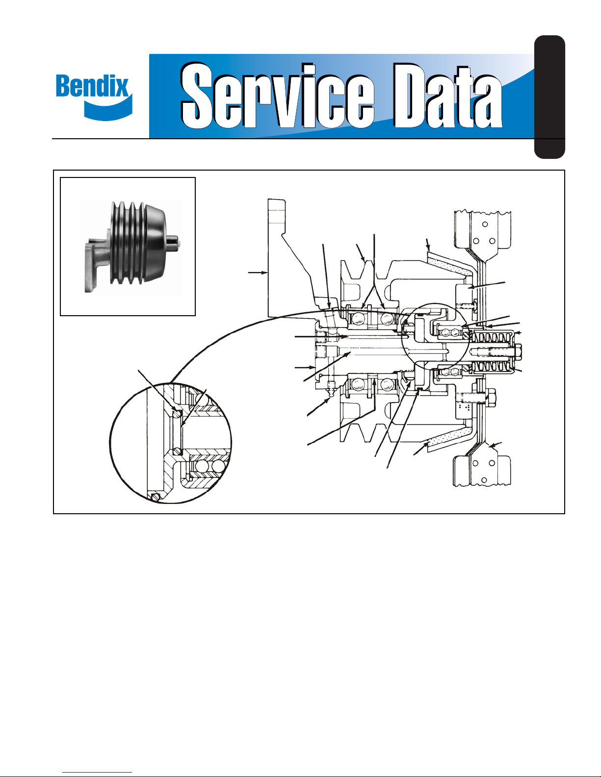
Bendix® FD-1™ Clutch Type Fan Drive
SD-09-8501
FIGURE 1
O-RING
BRACKET
TEFLON
BACK-UP
RING
AIR PASSAGE
SHAFT
GREASE
PASSAGE
GREASE
FITTING
SPACER
AIR INLET
BEARINGS
PULLEY
RETAINER NUT
PISTON
PRESSURE
PLATE
BEARING
RETAINER
DOUBLE ROW
BALL BEARING
FAN PILOT
SPRING
CAGE
SPRING
FAN
FRICTION
MATERIAL
FIGURE 2
DESCRIPTION
The Bendix® FD-1™ fan clutch is a pneumatically operated,
thermostatically controlled clutch for the engine cooling fan.
Its purpose is to maintain engine temperature by engaging
or disengaging the cooling fan, thereby providing better
fuel economy , greater engine efficiency , faster warm-ups and
a quieter vehicle.
The FD-1™ clutch is produced in several different models to
accommodate the variety of installation requirements
resulting from the many engine, vehicle and accessory
combinations. Its fail-safe design prevents overheating in
the event of air loss or component or air line failure.
OPERATION
GENERAL
The FD-1™ fan clutch replaces the standard fan hub on the
engine and is controlled by a temperature sensitive air valve
(see Fig. 5). The same valves used to control radiator
shutters are used to control the FD-1™ clutch. Installed in
the engine block, the control valve directly senses coolant
temperature. Provided coolant temperature remains below
the setting of the valve, air passes through it to disengage
the fan clutch. When coolant temperature rises to the valve
setting, it closes and exhausts air pressure from the fan
clutch which engages the fan.
1
Page 2
Depending upon optional equipment installed on the vehicle
such as radiator shutters and radiator mounted air
conditioning condenser, dif ferent piping arrangements are
necessary. These will be explained in the paragraph on
control systems.
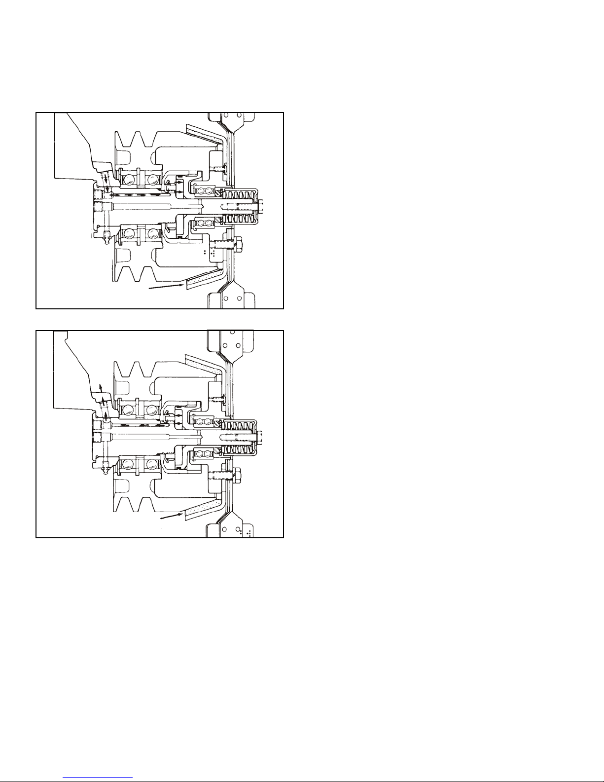
FAN DISENGAGED
FIGURE 3
ENGAGED
As the engine coolant rises in temperature, the engine
thermostat opens to circulate radiator coolant through the
engine. With further increase in coolant temperature, the
fan drive control valve closes and exhausts air from the
piston cavity when the engine coolant temperature reaches
the setting of the control valve. The fan clutch spring forces
the piston and pressure plate back on the shaft. When the
pressure plate lining contacts the pulley , the fan is engaged
and is driven by the engine (see Fig. 4).
CONTROL SYSTEMS
The fan clutch, in addition to its primary function of operating
the fan as needed to maintain the cooling liquid within a
certain temperature range, must be coordinated with other
devices when installed on the vehicle.
These are radiator shutters and radiator mounted condenser
for air conditioning. Four basic configurations are possible
as follows:
Figure 5. Fan Clutch only
Figure 6. Fan Clutch with shutters
Figure 7. Fan Clutch with radiator mounted air
conditioning condenser
Figure 8. Fan Clutch, shutters and condenser
FAN ENGAGED
FIGURE 4
DISENGAGED
When the vehicle is started with a cold engine the thermopneumatic control valve is open. As brake system air
pressure is built up, air passes through the control valve to
the fan clutch. Air enters the inlet port in the bracket of the
fan clutch and travels through the drilled passage in the
shaft to fill the piston cavity. When air in the piston cavity
reaches a pressure of 70-75 psi, the piston slides on the
shaft moving the pressure plate assembly and fan to the
disengaged position. In this position the clutch lining is out
of contact with the pulley and the fan is no longer driven by
the engine (see Fig. 3).
The objective in the case of Figure 5 is to not engage the fan
until the engine thermostat is fully open. The thermopneumatic control valve should therefore be calibrated to
release the air from the fan clutch when the coolant
temperature is at least 10°F . higher than the full open point
of the engine thermostat.
The objective in the case of Figure 6 is to not engage the
fan until the shutters are fully open. The fan control valve
should, therefore, engage the fan at a coolant temperature
10°F. higher than the shutter opening point. If the shutters
are the modulating type, the fan engagement should be at
least 10°F. higher than the full-open temperature of the
shutter.
In the case of Figure 7 the fan must be controlled to perform
the supplementary function of pulling cooling air through
the air conditioning condenser when required, although the
engine coolant may be below the fan cut-in temperature.
This is most likely to occur at high ambient temperatures
and low road speed or idling. If the condenser is
inadequately cooled, the air conditioning system will start
to build up a higher than normal pressure. Therefore, a
pressure switch is connected into the air conditioning
compressor discharge line, as shown in Figure 7. When
this pressure switch senses a higher than normal pressure
in the air conditioning system (approximately 250 P .S.I.), it
closes an electrical circuit which in turn energizes a solenoid
operated air supply valve which exhausts the air supply for
2
Page 3
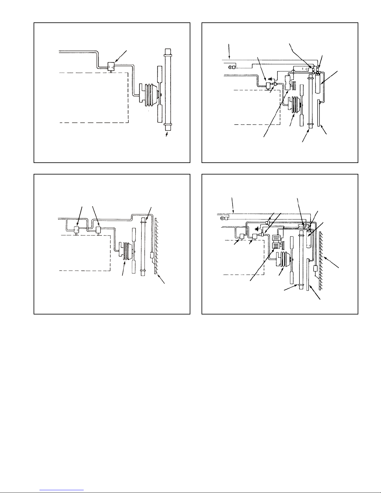
THERMO-PNEUMATIC
VALVE
AIR
CONDITIONING
SIGNAL
THERMO-PNEUMATIC
VALVE
FAN
OVERRIDE
SWITCH
AIR
CONDITIONING
OVERRIDE
SWITCH
RECEIVER
DRYER
BLOCK
FAN
CLUTCH
RADIATOR
FIGURE 5 FIGURE 7
CONDITIONING
THERMO-PNEUMATIC
VALVES
BLOCK
FAN
CLUTCH
RADIATOR
SHUTTER
SIGNAL
THERMO-PNEUMATIC
BLOCK
AIR COND.
COMPRESSOR
AIR
(NORMALLY OPEN)
VALVES
BLOCK
AIR COND.
COMPRESSOR
SOLENOID
VALVE
CLUTCH
SOLENOID VALVE
FAN
CLUTCH
RADIATOR
FAN
RADIATOR
FAN
OVERRIDE
SWITCH
CONDENSER
AIR
CONDITIONING
OVERRIDE
SWITCH
RECEIVER
DRYER
SHUTTER
CONDENSER
the fan control, causing the fan to engage. Most vehicles
also have an additional dual function pressure switch
connected in series with the air conditioner clutch. This
switch is normally open, closes at approximately 30 P.S.I.
and opens again at approximately 400 P.S.I. Its purpose is
to prevent operation of the air conditioning compressor if
the refrigerant is lost or to shut off the compressor if the
system pressure reaches a dangerously high pressure
(approximately 400 P.S.I.). This switch does not normally
have anything to do with fan operation; however, it is
sometimes combined with the previously mentioned override
switch.
Figure 8 depicts a combination of shutters, fan clutch and
air conditioning. This combination requires the two thermopneumatic controls for fan and shutters, as well as the
electro-pneumatic override for the air conditioning. With
this combination the same requirements for fan control apply
FIGURE 8FIGURE 6
as in Figure 6 and 7 with the additional requirement that the
shutters should be controlled in such a manner that they
always open whenever the air conditioning compressor
operates.
A variation of this combination consists of a two section
shutter with one section in front of the condenser and the
other in front of the remaining portion of the radiator. In this
combination only the section in front of the condenser needs
to open when the air conditioner engages.
PREVENTIVE MAINTENANCE
The durability of the Bendix® FD-1™ fan clutch matches that
of the vehicle’s engine when proper maintenance is
performed. Maintenance intervals for the FD-1™ clutch will
vary in relation to the type of service the vehicle performs.
The following is a guide:
3
Page 4

LINE HAUL VEHICLES:
Every 25,000 miles, 900 hours, or three months - whichever
occurs first-lubricate the FD-1™ clutch (SEE NOTE).
Every 50,000 miles, 1,800 hours, or every six months
whichever occurs first-perform the service checks outlined
in this manual.
CITY DELIVERY
Every 15,000 miles, 300 hours or two months - whichever
occurs first:
1. Perform the service checks outlined in this manual.
2. Lubricate the FD-1™ clutch (SEE NOTE).
NOTE: Prior to July , 1980, a grease provision was optional.
When this option was not included, permanently
lubricated components were installed. Most fan
clutches produced after July, 1980, include the
grease provision as a standard feature.
Lubricate the FD-1™ clutch with approximately 10 cubic
centimeters of CHEVRON SRI #2 or an equivalent grease.
SERVICE CHECKS
Before performing the operational and leakage checks,
apply the vehicle parking brakes or chock the wheels.
OPERA TIONAL
1. With the engine cold, the ignition off and at least 75 psi
air pressure in the brake system, note that the fan is
disengaged from the pulley and can be turned by hand.
If the fan can be turned, proceed to step #2. If it cannot
be turned:
A. Drain all reservoirs and disconnect the air control
line leading to the fan clutch and apply at least 75
psi shop air pressure to the fan clutch.
B. If the fan cannot be turned, the clutch is defective
and must be repaired or replaced (see appropriate
section of this manual).
C. If the fan can now be turned; check the air lines
leading to and from the thermostatic control valve
for “kinks” or obstructions, and check the control
valve itself according to the manufacturer’s
instructions.
2. After performing check #1, drain all air pressure from the
brake system. Note that the fan is now engaged and
cannot be turned by hand. If it cannot be turned, proceed
to test #3. If it can be turned, the clutch is defective and
must be repaired or replaced.
3. Check the operation of the thermostatic control valve by
running the engine up to operating temperature. Note
that the fan clutch engages when engine temperature
rises to normal or above and disengages after fan
cooling is accomplished. Normal engagement time
should not exceed two minutes. If engagement time does
4
not exceed two minutes, proceed to check #4. If
engagement time does exceed two minutes:
A. If this test is being performed for the first time after
installation of the fan clutch, recheck the setting of
the thermostatic control valve and compare it with
the setting of the engine coolant thermostat or in
the case of vehicles with radiator shutters, with the
setting of the shutter control. The fan clutch control
should always be 10° higher than the highest setting.
B. If the fan clutch installation has successfully passed
this test before, but does not do so now, the
thermostatic control valve is defective and should
be replaced.
4. Check the condition of the rear main bearings during
operation and note any excessive wobble or noise. The
pressure plate ball bearing and sliding piston can be
checked while the engine is off and the fan is
disengaged. “Rock” the fan from front to back at the
outer tip of the blade. If movement of the blade tip, front
to back, exceeds 3/8" (See fig. 5) the fan clutch must
be repaired or replaced.
5. Check the pressure plate lining thickness by measuring
the gap between the pressure plate edge and the pulley
face with the clutch engaged. The gap should not be
less than .120 inch or approximately 1/8 inch.
(9)
(8)
(13)
(11)
(10)
(3)
(2)
(1)
(4)
(5)
(6)
(15)
(14)
FIGURE 9
(7)
(12)
(14)
(15)
LEAKAGE CHECKS
In order to check for air leakage past the only two sliding
o-rings in the FD-1™ fan clutch, it is necessary to disconnect
the single air control line.
Check for leakage by connecting a 90 cu. in. reservoir (Bendix
part number 225000) with a gauge installed to the control
Page 5

port of the fan clutch. Af ter filling the 90 cu. in. reservoir with
100 psi, allow the pressure to stabilize and observe the time
required for the reservoir pressure to drop to 90 psi. If the
time required is less than 1 minute, leakage is excessive
and repair or replacement is necessary .
If the FD-1™ fan clutch fails to operate as described or
leakage is excessive, it is recommended that it be returned
to the nearest authorized Bendix outlet for a factory
remanufactured unit under the exchange plan. If this is not
possible, the FD-1™ clutch can be repaired with genuine
Bendix parts, in which case the following should be helpful.
NOTE: A pressure plate maintenance kit including pressure
plate and o-rings is available under pc. no. 288907.
O-ring kit only is pc. no. 289319.
27/32” DRILL THRU (2
HOLES FOR 3/4 BAR)
MAT’L O.H.T.S. TUBING
HDN & DRAW RC 40-45
5.38”
4.62”
4.25”
REMOVAL
It is recommended for ease of repair that the entire fan clutch
assembly be removed from the vehicle. Before removing the
fan clutch apply the vehicle parking brakes or check the
wheels and drain all brake system air pressure.
1. Remove the six cap screws which hold the fan clutch
pressure plate and remove the fan.
2. Loosen the fan belts and remove the fan clutch assembly.
DISASSEMBLY
1. Remove the 3/8 inch cap screw (1) and washer (2) from
the radiator end of the fan hub shaft (see Fig. 9).
2. Remove spring cover (3), spring (4), and thrust washer
(5).
3. Remove pressure plate assembly complete and set
aside.
4. Disengage lock tab on lock washer (6) (see Fig. 9) and
remove bearing nut (7), using a spanner tool as shown
in Fig. 10.
5. Remove lockwasher, piston housing (8) and o-ring (9)
(see Fig. 9).
6. Support the back side of the pulley so that the shaft
bracket assembly can be pressed down far enough to
remove the pulley assembly. Since the bearings are
originally installed with Locktite between shaft and
bearings, a force as high as 5000 lbs. may be required
to remove the pulley assembly . If the shaft is to be reused,
a cap screw should be screwed into the end of the shaft
to protect the end of the shaft from damage.
PRESSURE PLATE DISASSEMBLY
1. Remove three Phillips screws (10) (Fig. 9).
2. Remove pressure plate (11).
3. Remove the large o-ring (12) from the O.D. of the piston
(13) and the small o-ring (14) and Teflon backup ring
(15) from the internal groove in the bore of the piston.
(See enlarged view in circle) NOTE: Fans manufactured
prior to Jan. 1979 do not have the Teflon back-up ring
and the groove is not wide enough to accept one.
I< 2.080
2.75”
FIGURE 10
+ .005 >I
+ .002 CENTERED
.235
(4 LUGS)
1/32” FLAT
4. In fan assemblies manufactured prior to December 1976
the piston in the bearing retainer/piston sub-assembly
is die cast aluminum and is retained in the bearing by
Locktite and lock ring.
After December 1976 the piston is of cast iron retained
in the bearing by a lock nut. In any case, the bearing
retainer , bearing, piston, lock ring and lock nut comprise
a sub-assembly and must be serviced as such. The
aluminum piston version should always be replaced with
the later version with the cast iron piston. Refer to the
Bendix Parts Catalog for part identification.
PULLEY DISASSEMBL Y (See Fig. 1 1)
1. Support pulley on front (tapered) end. Displace spacer
(1) eccentrically as far as possible. With a round
pressing tool which fits loosely through the I.D. of the
top bearing, press the bottom bearing out (3) pressing
on the eccentrically positioned spacer .
2. Remove the tapered snap ring (2), using Waldes Tool
#6500. The remaining bearing (4) may now be pressed
out towards the rear of the pulley , leaving snap ring (5)
in pulley if pulley is to be reused.
3. In the case of closely spaced matched bearings such
as shown in Fig. 12, remove the snap ring and press
both bearings out the rear of the pulley .
This completes normal disassembly of the fan clutch.
The bracket-shaft assembly is normally recommended
to be serviced as an assembly .
5
Page 6

PULLEY
(4)
SEAL
FIGURE 1 1
(2)
(1)
(5)
SEAL
(3)
O.D. REF.
REASSEMBLY
ASSEMBL Y OF PULLEY-BEARING SUB-ASSEMBL Y
1. (Sp aced bearing assembly) (Fig. 1 1) Install snap ring (5)
using WaIdes Truarc snap ring plier 6500 or equivalent.
2. Support the pulley on the front or tapered end. Press in
bearing (4), seal side up, until bearing bottoms on snap
ring (5). Pressing fixture should contact outer race.
3. Install tapered snap ring (2), flat side towards bearing,
using Waldes tool #6500.
4. Invert pulley, tapered end up. Position spacer (1)
concentric with inner race of previously installed bearing.
Pack grease (Chevron SRI #2) around spacer. Press
in second bearing (3), seal side up, until inner race
contacts spacer . Pressing fixture must contact both inner
and outer races.
5. (Matched Bearings) To install the closely spaced
bearings as shown in Fig. 12, matched bearings 291458
must be used. Support the pulley on the front or tapered
end and press in the first bearing, seal side down, until
bearing bottoms on shoulder in pulley. Press on outer
race of bearing. Press in second bearing, seal side up,
bottoming on first bearing.
6. Install tapered snap ring.
PULLEY
MATCHED
BEARINGS TO BE
SEAL
TAPERED
SNAP RING
FIGURE 12
SEAL
ASSEMBLED WITH
SEALS AS SHOWN
CLEANING AND INSPECTION
After disassembly is complete:
1. Wash all metal parts, with the exception of the pressure
plate and lining, in a cleaning solvent and dry them.
2. Inspect parts not included in the maintenance kit for
nicks, burrs, corrosion and/or excessive wear.
3. Replace any part not considered reusable, after
inspection, with genuine Bendix replacement parts only .
ASSEMBLY OF PULLEY ASSEMBLY ON BRACKET
SHAFT
1. Support bracket with shaft pointing up. Apply one band
of Loctite RC 601 around shaft for each bearing as
shown in Fig. 9. Apply one band of Loctite RC 601 on
each race.
NOTE: When using Loctite, parts must be clean and free
of oil and grease. Allow 24 hours for complete curing.
2. Slide pulley assembly on shaft, making sure the bottom
bearing inner race bottoms against bracket.
3. Position o-ring (9) as shown in Fig. 9. Install piston cup
(8), lockwasher (6) with single tang located in groove in
shaft, and bearing nut (7). A tool similar to that shown in
Fig. 10 may be fabricated to tighten the bearing nut to
100-150 ft. lbs. One tang on the lockwasher must then
be bent up into the appropriate slot in the nut. Care must
be taken not to injure the finish on the I.D. of the piston
cup.
FINAL ASSEMBLY (Ref. Fig. 9)
1. Support bracket-shaft pulley assembly with shaft pointing
up. Lubricate inner surface of piston housing and lower
half of shaft with lubricant BW 655M.
2. Lubricate the large o-ring (12) and install on piston. Install
the T eflon back-up ring (15) (if used) in the internal groove
in the piston (13), then lubricate and install the smaller
6
Page 7

o-ring (14). Slide bearing retainer/piston assembly in
place over shaft. Make sure the indexing finger on piston
(13) is aligned with the corresponding gap in the side
wall of piston cup (8). Push the pressure plate assembly
all the way home until the piston bottoms in the piston
housing.
3. Install spacer (5), spring (4), spring retainer (3), washer
(2) and cap screw (6). A new cap screw should always
be used (because of the coating on the threads). T orque
the cap screw to 300 inch pounds.
4. Apply air pressure in control port of bracket or shaft
(80-120 psi). This will extend the bearing retainer/ piston
assembly so the pressure plate can be positioned and
the three Phillips head screws (10) started and torqued
to 40 in. lbs. (It may be easier to torque the Phillips
head screws if the air pressure in the clutch is released
after the screws are started.)
TEST
1. With no air pressure applied, the gap between the
pressure plate edge and the pulley face line should be
.375 in. ± .04. With 120 psi air pressure applied, the gap
may be .526 in. maximum (see Fig. 9).
2. With no air pressure applied, the torque required to rotate
the clutch must not exceed 150 in. oz.
3. With 70-75 psi applied, the pressure plate must rotate
freely , separate from the pulley.
4. Perform the leakage checks outlined in the manual.
5. Do not overtighten engine fan belts.
RETROFIT INST ALLA TION INFORMA TION
To determine which fan clutch piece number should be
purchased when retrofitting existing equipment, consult the
nearest authorized Bendix parts outlet for assistance.
Complete installation instructions and piping diagrams are
packed with each FD-1™ fan clutch.
It is recommended that only cooling fans approved by the
vehicle or fan manufacturer be installed on the FD-1™ fan
clutch.
WARNING! PLEASE READ AND FOLLOW
THESE INSTRUCTIONS TO AVOID
PERSONAL INJURY OR DEATH:
When working on or around a vehicle, the following
general precautions should be observed at all times.
1. Park the vehicle on a level surface, apply the
parking brakes, and always block the wheels.
Always wear safety glasses.
2. Stop the engine and remove ignition key when
working under or around the vehicle. When
working in the engine compartment, the engine
should be shut off and the ignition key should be
removed. Where circumstances require that the
engine be in operation,
be used to prevent personal injury resulting from
contact with moving, rotating, leaking, heated or
electrically charged components.
3. Do not attempt to install, remove, disassemble or
assemble a component until you have read and
thoroughly understand the recommended
procedures. Use only the proper tools and observe
all precautions pertaining to use of those tools.
4. If the work is being performed on the vehicle’s air
brake system, or any auxiliary pressurized air
systems, make certain to drain the air pressure from
all reservoirs before beginning ANY work on the
vehicle. If the vehicle is equipped with an AD-IS
air dryer system or a dryer reservoir module, be
sure to drain the purge reservoir.
5. Following the vehicle manufacturer’s
recommended procedures, deactivate the electrical
system in a manner that safely removes all
electrical power from the vehicle.
6. Never exceed manufacturer’s recommended
pressures.
7. Never connect or disconnect a hose or line
containing pressure; it may whip. Never remove a
component or plug unless you are certain all
system pressure has been depleted.
8. Use only genuine Bendix® replacement parts,
components and kits. Replacement hardware,
tubing, hose, fittings, etc. must be of equivalent
size, type and strength as original equipment and
be designed specifically for such applications and
systems.
9. Components with stripped threads or damaged
parts should be replaced rather than repaired. Do
not attempt repairs requiring machining or welding
unless specifically stated and approved by the
vehicle and component manufacturer.
10. Prior to returning the vehicle to service, make
certain all components and systems are restored
to their proper operating condition.
EXTREME CAUTION should
™
7
Page 8

8
BW1451 © 2004 Bendix Commercial Vehicle Systems LLC All rights reserved. 4/2004 Printed in U.S.A.
 Loading...