

Page 1
®
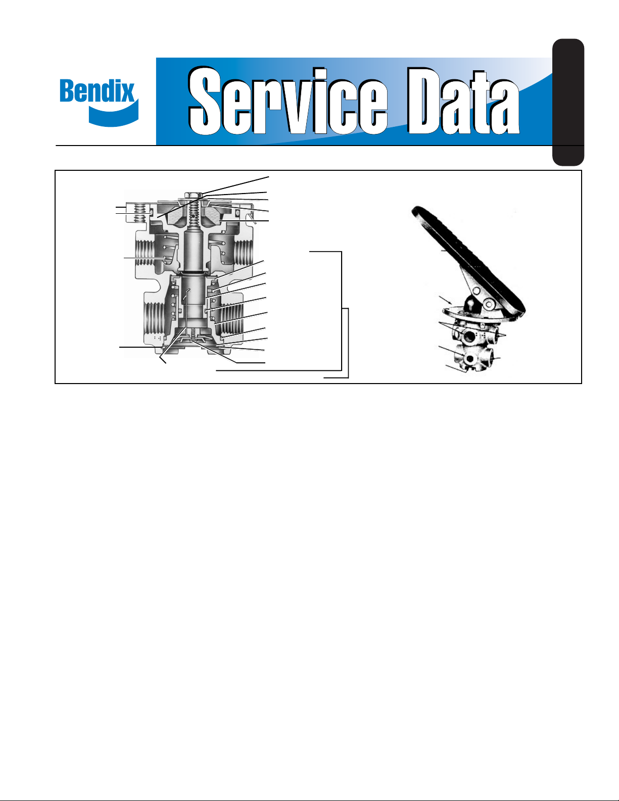
Bendix® E-2™ & E-3™ Brake Valves
CAP SCREW
PISTON
4
RETAINER
3
O-RING
WASHER
SPRING SEAT
RUBBER SPRING
SD-03-812
6
7
8
9
10
PISTON
2
RETURN
SPRING
RETAINING
1
FIGURE 1 E-3™ BRAKE V ALVE (SECTIONAL VIEW)
RING
PRELOAD
SPRING
21
RETAINER
VALVE SPRING
INLET/EXHAUST
VALVE
O-RING
EXHAUST CH.
VALVE SEAT
O-RING
DIAPHRAGM
WASHER
SCREW
INSERT ASS’Y
12
14
17
20
15
DESCRIPTION
The Bendix® E-2™ and E-3™ brake valves are single circuit
brake valves that provide the driver with single point control
of the service braking system. The valve can be either treadle
operated or fitted with a lever for a linkage connection to a
conventional brake pedal. Movement of the treadle or pedal
controls the graduated application and release of air pressure
to the vehicle brake actuators, applying or releasing the
vehicle brakes.
The E-2™ and E-3™ brake valves utilize a rubber spring
confined in a retainer, resulting in reduced plunger travel as
compared to previous design single circuit brake valves.
The E-3™ brake valve differs from the E-2™ valve in that it
employs a different piston (see insert Fig. 1), which requires
greater plunger travel. Because of the greater plunger travel,
the E-3™ valve provides less sensitivity in the 0-40 psi
application range as compared to the E-2™ valve. Other than
the different pistons, the E-2™ and E-3™ valves are identical.
An identification washer, located under the ret aining ring in
the valve’s exhaust port, provides a means of identifying the
E-2™ and E-3™ brake valve.
The E-2™ and E-3™ valves have an insert type inlet/exhaust
valve assembly which can be removed without disconnecting
air lines. An exhaust check valve in the bottom of the insert
prevents contaminants from entering the valve through the
TREADLE
13
MOUNTING
PLATE
16
18
19
11
DELIVERY
PORTS (4)
AUXILIARY
PORTS (2)
EXHAUST
E-2™ - E-3™ BRAKE V AL VE
SUPPLY
PORTS (2)
exhaust port. An optional exhaust extension is available
should an exhaust carry-off line be required.
Porting consists of two (2) 1/2 inch p.t. supply ports, four (4)
3/8 inch or 1/2 inch p.t. delivery ports, and two (2) 1/4 inch
p.t. accessory ports (in the supply portion of the valve).
OPERATION
Applying
Applying the treadle or pedal exerts a force on the plunger,
rubber graduating spring and piston. The downward
movement of the piston causes the piston stem (which is
the exhaust seat) to contact the valve, closing the exhaust.
As the exhaust closes, the inlet valve moves away from its
seat. Air pressure is then allowed to flow by the inlet valve,
out the delivery ports and to the brake actuators, applying
the brakes.
Balanced
When the air pressure in the cavity beneath the piston and
the air pressure being delivered to the brake actuators equals
the mechanical force on the top of the piston, the piston
lifts and the inlet valve closes, cutting off any further flow of
air from the supply line through the valve. The exhaust
remains closed, preventing any escape of air through the
exhaust port.
Page 2

When applications in the above average pressure range are
made, the valve reaches a balanced position as the air
pressure beneath the piston equals the effort exerted by the
driver’s foot on the pedal or treadle. When the piston is
pressed down all the way , the inlet valve remains open and
reservoir pressure is delivered to the actuators.
Releasing
Fully apply valve and hold application. Coat exhaust port
with soapsuds. NO leakage permitted. Coat area around
top of valve with soapsuds. NO leakage permitted.
If the valve does not function as described or leakage is
excessive, it is recommended that it be replaced with a new
or remanufactured unit, or repaired with genuine Bendix parts
available at our distributors.
When the treadle or pedal application is released, mechanical
force is removed from the top of the piston, air pressure
beneath the piston lifts the piston; (the inlet valve is closed)
the exhaust in the valve is open and the air beneath the
piston and in the delivery lines is exhausted through the
exhaust port.
PREVENTIVE MAINTENANCE
Important: Review the warranty policy before performing
any intrusive maintenance procedures. An extended warranty
may be voided if intrusive maintenance is performed during
this period.
Because no two vehicles operate under identical conditions,
maintenance and maintenance intervals will vary . Experience
is a valuable guide in determining the best maintenance
interval for any one particular operation.
Visually check for physical damage to the brake valve such
as broken air lines and broken or missing parts.
Every 3 Months, 25,000 Miles or 900 Operating Hours
Lubricate all mechanical actuation (pedal) parts with light
(10W) oil. Apply 2 to 4 drop s of oil between the plunger and
mounting plate. DO NOT OVER OIL!!!
Lever/linkage operated valves should be adjusted so that
the roller just contacts plunger . Check for integrity of mounting
plate and treadle and/or pedal.
SERVICE TESTS
Operating Test (IMPORTANT!!! Tests should be
conducted with an accurate test gauge.)
Install gauge in a delivery port or line; depress the treadle or
pedal to several positions between fully released and fully
applied positions, checking the delivery pressure on the
gauge to see that it varies proportionately with the movement
of the treadle or pedal. In the fully applied position, the
reading on the gauge should be approximately that of full
reservoir pressure. Upon release of the application, the
reading of the test gauge should fall to zero psi immediately .
Leakage Test
With 100 psi supply pressure and valve in released position,
coat exhaust port with soapsuds arid check for leakage.
NO leakage permitted.
REMOVING AND INSTALLING
Removing
Block and hold vehicle by means other than air brakes.
Drain air brake system.
*If only the insert is to be removed, remove retaining ring,
and pull insert out.
If entire valve is to be removed, disconnect air lines from
valve.
Remove mounting bolts and remove valve.
Installing
Clean air lines connecting to valve.
Install valve and tighten mounting bolts.
Connect air lines to valve (plug any unused ports).
T est valve as outlined under “Service Tests.”
NOTE: When installing a new or rebuilt insert, precheck
movement of the inlet and exhaust valve in the
exhaust seat by depressing the insert. Precaution
should be taken to prevent damage to the inlet and
exhaust valve and the exhaust check valve grommet,
when installing the insert in the valve. After placing
the insert in the valve body, depress the exhaust
check valve seat and install the retaining ring. Make
sure the retaining ring snaps into the body groove.
DISASSEMBLY
NOTE: Disassembly and assembly instructions are keyed
to Fig. 1 sectional view.
1. Remove treadle or lever assembly, boot and plunger .
2. Depress piston assembly and remove retainer (4).
3. Remove piston assembly (7) and piston return spring (2)
from body .
4. Remove o-ring (3) from piston (7).
5. Remove cap screw (6), washer (8), spring seat (9),
and rubber spring (10) from piston assembly (7).
6. Remove retaining ring (1) and inlet/exhaust insert
assembly (1 1) from body.
2
Page 3

Insert Disassembly
NOTE: It is recommended that entire inlet/exhaust insert
be replaced as an assembly .
7. Remove o-ring (17) from check valve seat (16).
8. Remove screw (20), washer (19), and diaphragm (18).
9. Depress and hold insert, and remove preload spring (21).
10.Remove inlet/exhaust valve (14), valve spring (13), and
o-ring (15).
1 1. Remove valve retainer (12).
Cleaning and Inspection
Wash all metal parts in mineral spirits and dry. Wipe all
rubber parts clean.
Inspect all parts for excessive wear or deterioration.
Inspect valve and valve seats for nicks and burrs.
Check springs for cracks, distortion or corrosion.
Inspect exhaust check diaphragm for flexibility, wear, and
deterioration.
Replace all parts not considered serviceable during these
inspections.
ASSEMBL Y
1. Lightly lubricate the piston, valve bores, and o-rings with
Dow Corning 55-M pneumatic grease (Our piece number
291 126).
2. Position rubber spring (10) in piston (7).
3. Install spring seat (9), washer (8), and cap screw (6).
T orque cap screw to 50 inch pounds.
4. Install piston o-ring (3) and place piston return spring (2)
in body .
5. Install piston retainer (4). Be certain the prongs snap
over groove in valve body .
Insert Assembly
6. Position preload spring (21) in exhaust check valve seat
(16).
7. Install diaphragm (18), diaphragm washer (19) (with lips
pointing out), and install screw (20). Tighten screw
securely .
8. Install o-ring (15) and valve retainer (12) on inlet / exhaust
valve body (14).
9. Install valve spring (13) on exhaust check valve seat (16)
and install inlet/exhaust valve (14) into exhaust valve seat
(16). Press the valve down until the preload spring snaps
and holds the assembly together.
10.Install o-ring (17) on exhaust check valve seat (16).
11. Place inlet/exhaust insert in valve body; position
identification washer. Press the insert down while
installing retaining ring (1). Make certain retaining ring
snaps into body groove, thus locking in the insert in
place.
T esting A Rebuilt E-2™ or E-3™ Brake Valve
Perform operating and leakage tests as outlined in “Service
Tests” section.
WARNING! PLEASE READ AND FOLLOW
THESE INSTRUCTIONS TO AVOID
PERSONAL INJURY OR DEATH:
When working on or around a vehicle, the following
general precautions should be observed at all times.
1. Park the vehicle on a level surface, apply the
parking brakes, and always block the wheels.
Always wear safety glasses.
2. Stop the engine and remove ignition key when
working under or around the vehicle. When
working in the engine compartment, the engine
should be shut off and the ignition key should be
removed. Where circumstances require that the
engine be in operation,
be used to prevent personal injury resulting from
contact with moving, rotating, leaking, heated or
electrically charged components.
3. Do not attempt to install, remove, disassemble or
assemble a component until you have read and
thoroughly understand the recommended
procedures. Use only the proper tools and observe
all precautions pertaining to use of those tools.
4. If the work is being performed on the vehicle’s air
brake system, or any auxiliary pressurized air
systems, make certain to drain the air pressure from
all reservoirs before beginning ANY work on the
vehicle. If the vehicle is equipped with an AD-IS
air dryer system or a dryer reservoir module, be
sure to drain the purge reservoir.
5. Following the vehicle manufacturer’s
recommended procedures, deactivate the electrical
system in a manner that safely removes all
electrical power from the vehicle.
6. Never exceed manufacturer’s recommended
pressures.
7. Never connect or disconnect a hose or line
containing pressure; it may whip. Never remove a
component or plug unless you are certain all
system pressure has been depleted.
8. Use only genuine Bendix® replacement parts,
components and kits. Replacement hardware,
tubing, hose, fittings, etc. must be of equivalent
size, type and strength as original equipment and
be designed specifically for such applications and
systems.
9. Components with stripped threads or damaged
parts should be replaced rather than repaired. Do
not attempt repairs requiring machining or welding
unless specifically stated and approved by the
vehicle and component manufacturer.
10. Prior to returning the vehicle to service, make certain all components and systems are restored to
their proper operating condition.
EXTREME CAUTION should
™
3
Page 4

BW1564 © 2004 Bendix Commercial Vehicle Systems LLC. All rights reserved. 3/2004 Printed in U.S.A.
 Loading...