

Page 1
®
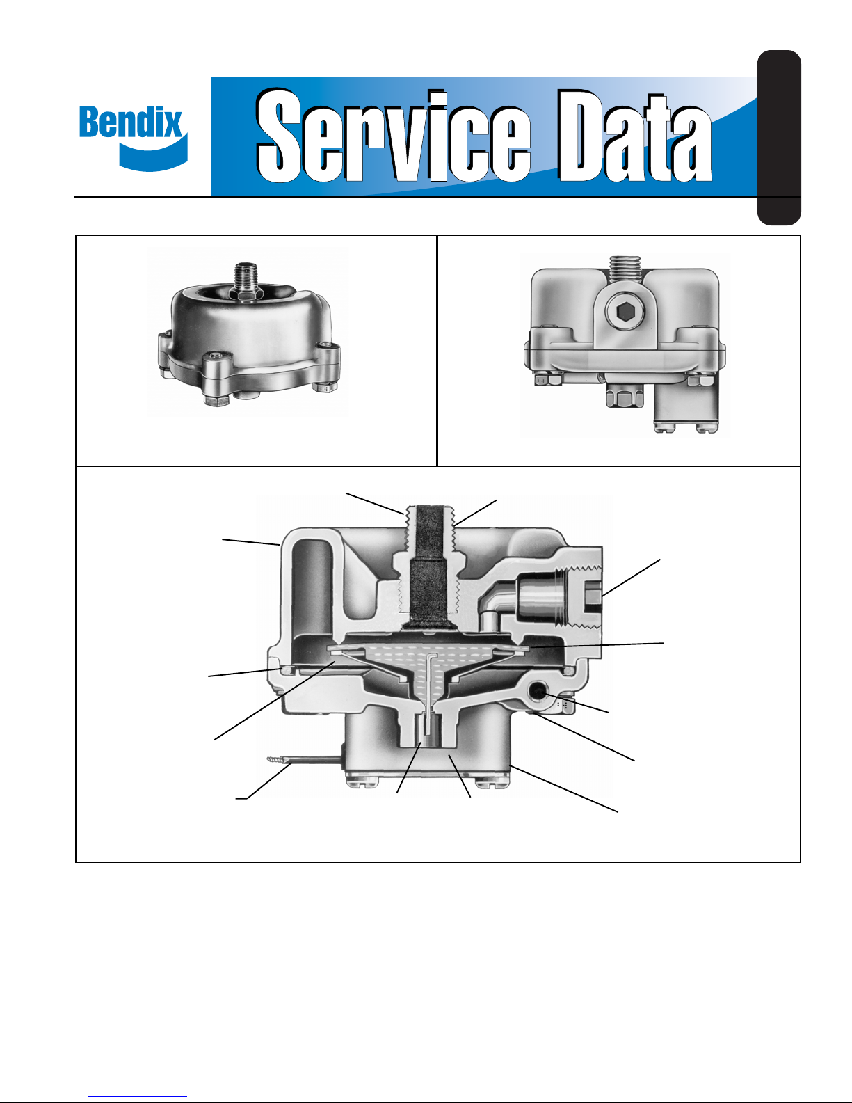
Bendix® DV-2™ Automatic Reservoir Drain Valve
SD-03-2501
BODY
SEALING
RING
VALVE
GUIDE
ELECTRICAL
LEAD WIRE
STANDARD DV-2
VALVE
™
ADAPTER
WIRE STEM
DV-2™ VALVE WITH HEATER AND THERMOSTAT
DV-2™ VALVE WITH
HEATER
RESERVOIR
EXHAUST
PORT
TOP
PORT
SIDE
RESERVOIR
PORT
INLET &
EXHAUST
VALVE
HEATER ELEMENT
COVER
THERMOSTAT
HOUSING
DESCRIPTION
The DV-2™ automatic reservoir drain valve ejects moisture
and contaminants from the reservoir in which it is connected.
It operates automatically and requires no manual assistance
or control lines from other sources.
The automatic reservoir drain valve has a die cast aluminum
body and cover and is normally mounted either in the bottom
of the reservoir using the top port of the drain valve or in the
end of an end drain reservoir using the side port of the valve.
The DV-2™ valve is also available with a heater and thermostat
cast into the cover for vehicles operated in subfreezing
temperatures. The heated DV-2™ valve is supplied in either
a 12 or 24 volt model and in bottom or end drain configuration.
A 1/4" male pipe adapter is supplied with all DV-2™ drain
valves, end drain and bottom drain, both standard and heated.
This adapter should be installed directly into the reservoir.
Early versions included a filter screen in the adapter. The
filter should be discarded. Later versions may have a standard
pipe nipple instead of the adapter.
1
Page 2
NOTE: If a vehicle equipped with a DV-2™ automatic drain
valve(s) is operated in subfreezing temperatures, it
is recommended that a heated reservoir drain valve
is installed.
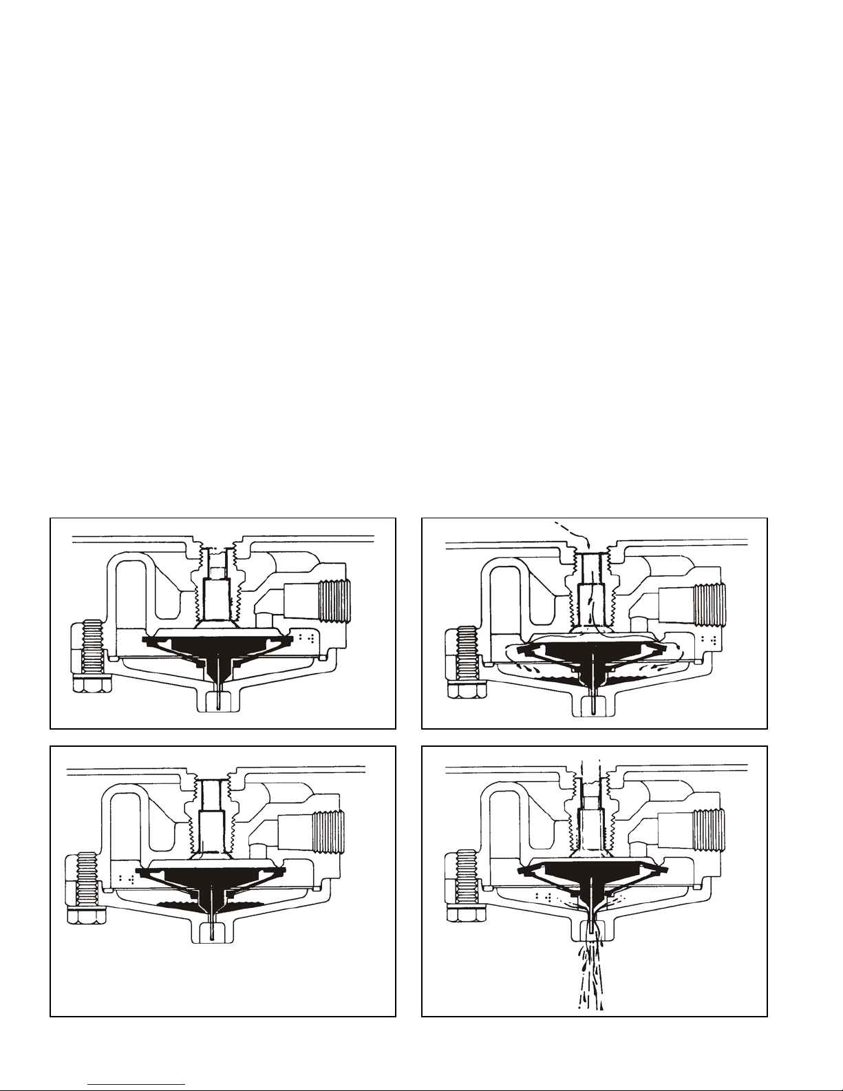
OPERATION
Referring to Figure 1, with no air pressure in the system, the
inlet and exhaust valves are closed. Upon charging the
system, a slight pressure opens the inlet valve (Figure 2)
which permits air and contaminants to collect in the sump.
The inlet valve remains open when pressure is ascending in
the system until maximum (governor cutout) pressure is
reached. The spring action of the valve guide in the sump
cavity closes the inlet valve. The inlet valve and the exhaust
valve are now closed (Figure 3).
Manual draining can be accomplished as follows:
Using a tool, move the wire in the exhaust port upward,
holding it in until draining is completed.
™
The thermostat on the heated model DV-2
automatic drain
valve will activate the heating element when the valve body
reaches a temperature of approximately 45°F and will
deactivate the heating element when the valve body is
warmed to approximately 85°F .
PREVENTIVE MAINTENANCE
Important: Review the Bendix Warranty Policy before
performing any intrusive maintenance procedures. A warranty
may be voided if intrusive maintenance is performed during
the warranty period.
When reservoir pressure drops slightly (approximately 2 psi),
air pressure in the sump cavity opens the exhaust valve
(Figure 4) and allows moisture and contaminants to be
ejected from the sump cavity until pressure in the sump
cavity drops sufficiently to close the exhaust valve.
The length of time the exhaust valve remains open and the
amount of moisture and contaminants ejected depends upon
the sump pressure and the reservoir pressure drop that
occurs each time air is used from the system.
No two vehicles operate under identical conditions, as a
result, maintenance intervals may vary. Experience is a
valuable guide in determining the best maintenance interval
for air brake system components. At a minimum, the
automatic reservoir drain valve should be inspected every 6
months or 1500 operating hours, whichever comes first, for
proper operation. Should the automatic reservoir drain valve
not meet the elements of the operational tests noted in this
document, further investigation and service of the valve may
be required.
FIGURE 1 FIGURE 2
FIGURE 3 FIGURE 4
2
Page 3

Upon investigation, parts showing signs of wear or
deterioration should be replaced.
If there is a filter screen in the adapter fitting it should be
removed and discarded.
SERVICE CHECKS
OPERATING TEST
With system charged, make several foot valve applications
and note each time an application is made, an exhaust of
air occurs at the exhaust port of the drain valve. If no air
comes out, push the wire stem. If no air comes out, there
may be a plugged filter in the adapter which should be removed
and discarded.
LEAKAGE TEST
With system charged and pressure stabilized in system,
there should be no leaks at the drain valve exhaust. A constant
slight exhaust of air at the drain valve exhaust could be
caused by excessive leakage in the air brake system.
™
If the DV-2
described or if leakage is excessive, it is recommended
that it be replaced with a new or remanufactured unit or
repaired with genuine Bendix parts.
automatic drain valve does not function as
INSTALLING
Block and hold vehicle by means other than air brakes. Drain
air system.
™
To avoid early fouling at the DV -2
valve, thoroughly finish
and clean the reservoir before installing the drain valve.
Aerate any tank thoroughly if any solvents have been used
in the cleaning process.
IMPORTANT
When installing a DV-2™ drain valve equipped with a heater
and thermostat, first determine if the vehicle electrical system
is 12 or 24 volt, and that the heater/thermostat unit is of the
same voltage. The #14 gauge lead wire on the valve should
be connected to the “on” position of the engine control or
ignition switch. Use an 8 amp fuse for one valve, a 15 amp
fuse for two valves, and a 20 amp fuse for three valves. All
electrical connections must be waterproof.
CLEANING AND INSPECTION
Cleaning solvent may be used on metal parts. Rubber parts
should be wiped clean.
Inspect all parts for wear or deterioration. Discard filter screen
if present.
INSTALLING AND REMOVING
REMOVING
Block and hold vehicle by means other than air brakes. Drain
air system.
Disconnect heater wire if valve is so equipped. Remove
automatic reservoir drain valve.
DISASSEMBLY
Remove 4 cap screws and lock washers. Remove cover and
sealing ring.
™
NOTE: The heater and thermostat of the DV-2
equipped are not serviceable. If the heater or
thermostat has failed, the entire cover must be
replaced. Do not remove the thermostat cover plate.
It is moisture sealed and removal could result in
early thermostat failure.
Remove valve guide.
Remove inlet and exhaust valve.
Remove adapter and filter assembly (if filter present).
Remove filter retainer (if any).
Remove filter (if any).
valve’s so
Replace all parts not considered serviceable during these
inspections.
Bendix Field Maintenance Kit 282134 contains all parts
™
necessary for servicing all models of the DV-2
valve.
ASSEMBLY
Before assembling the valve, apply a light film of grease on
inlet valve seat.
DO NOT APPLY OIL TO THE INLET AND EXHAUST VALVE.
Place sealing ring in groove of cover.
Place valve guide over inlet and exhaust valve.
Place valve guide and inlet and exhaust assembly into cover
(wire will project through exhaust port).
Place body on cover and install cap screws and lockwashers.
Install adapter or pipe nipple in appropriate port.
Install drain valve in reservoir and reconnect heater wire if
drain valve is so equipped.
NOTE: Covers on the standard and heated drain valves can
be interchanged.
TESTING
VAL VE
REBUILT AUTOMATIC RESERVOIR DRAIN
3
Page 4

Perform “Operating and Leakage Checks” as outlined in this
section.
GENERAL SAFETY GUIDELINES
WARNING! PLEASE READ AND FOLLOW
THESE INSTRUCTIONS TO AVOID
PERSONAL INJURY OR DEATH:
When working on or around a vehicle, the following general
precautions should be observed at all times.
1. Park the vehicle on a level surface, apply the
parking brakes, and always block the wheels.
Always wear safety glasses.
2. Stop the engine and remove ignition key when
working under or around the vehicle. When
working in the engine compartment, the engine
should be shut off and the ignition key should be
removed. Where circumstances require that the
engine be in operation, EXTREME CAUTION should
be used to prevent personal injury resulting from
contact with moving, rotating, leaking, heated or
electrically charged components.
5. Following the vehicle manufacturer’s
recommended procedures, deactivate the
electrical system in a manner that safely removes
all electrical power from the vehicle.
6. Never exceed manufacturer’s recommended
pressures.
7. Never connect or disconnect a hose or line
containing pressure; it may whip. Never remove a
component or plug unless you are certain all
system pressure has been depleted.
8. Use only genuine Bendix® replacement parts,
components and kits. Replacement hardware,
tubing, hose, fittings, etc. must be of equivalent
size, type and strength as original equipment and
be designed specifically for such applications and
systems.
9. Components with stripped threads or damaged
parts should be replaced rather than repaired. Do
not attempt repairs requiring machining or welding
unless specifically stated and approved by the
vehicle and component manufacturer.
3. Do not attempt to install, remove, disassemble or
assemble a component until you have read and
thoroughly understand the recommended
procedures. Use only the proper tools and observe
all precautions pertaining to use of those tools.
4. If the work is being performed on the vehicle’s air
brake system, or any auxiliary pressurized air
systems, make certain to drain the air pressure
from all reservoirs before beginning ANY work on
the vehicle. If the vehicle is equipped with an
AD-IS® air dryer system or a dryer reservoir
module, be sure to drain the purge reservoir.
10. Prior to returning the vehicle to service, make
certain all components and systems are restored
to their proper operating condition.
11. For vehicles with Antilock Traction Control (ATC),
the ATC function must be disabled (ATC indicator
lamp should be ON) prior to performing any vehicle
maintenance where one or more wheels on a
drive axle are lifted off the ground and moving.
BW1457 © 2007 Bendix Commercial Vehicle Systems LLC. All rights reserved. 3/2007 Printed in U.S.A.
4
 Loading...