

Page 1
®
Bendix® BP-1™ Brake Proportioning Valves
SD-03-952
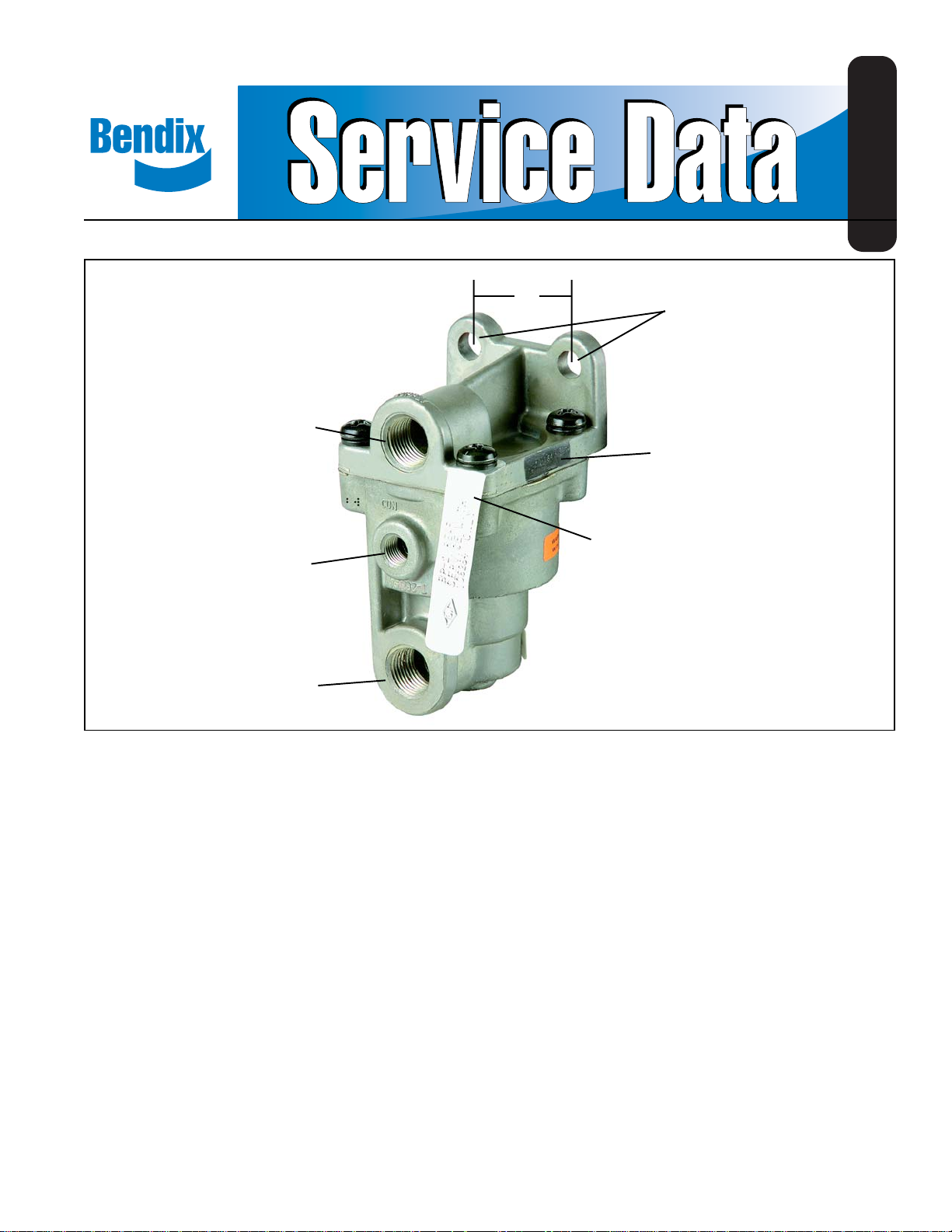
3/8 P.T.
SUPPLY PORT
1/8 P.T.
CONTROL PORT
3/8 P.T.
DELIVERY PORT
FIGURE 1 BP-1™ BRAKE PROPORTIONING VALVES
1.5
.340”
MOUNTING
HOLES (2)
PIECE NO.
STAMPED HERE
I.D. TAG STAMPED
BP-1 FRONT OR
BP-1 REAR
DESCRIPTION OF THE BP-1™ VALVES
The BP-1™ brake proportioning valves are incorporated into
the air brake systems to improve the controllability and
reduce the stopping distance of bobtail tractors during
braking. BP-1™, front and rear, valves reacting to the lack of
pressure in the trailer supply line reduce the braking effort
on the rear axles and increase the braking effort on the front
axle of tractors operating in the bobtail mode. Treadle
application force during bobtail operation resembles treadle
application force during normal operation with a connected
trailer.
A typical brake proportioning system is shown in Figure 6.
The system consists of a front and a rear brake proportioning
valve and a TR-3™ valve.
Caution: The BP-1™ front and BP-1™ rear valves are similar
in appearance but are NOT interchangeable. Note
identification tag attached to one of the cover
screws (Figure 1); it will be stamped ‘BP-1 Front’
or ‘BP-1 Rear’. The BP-1™ rear valve can be used
without installing a BP-1™ front valve, providing the
vehicle does not have a front axle ratio valve. If the
vehicle has a front axle ratio valve, the ratio valve
must be replaced with a BP-1™ front valve.
OPERATION
A tractor that is equipped with the BP-1™ rear brake
proportioning valve and TR-3™ valve only will respond in the
following manner. With the trailer supply valve pushed in
and a service brake application made, equal pressure (100%
of service application) will be delivered to each axle of the
tractor and trailer. When the trailer is disconnected from the
tractor and the trailer supply valve is pulled out, the front
axle of the tractor will receive 100% of the service brake
application pressure and the rear axle or axles approximately
25%. As application pressure increases, the differences
between the front axle and the rear axle(s) pressures
diminish.
1
Page 2

A tractor that is equipped with both a front and rear axle
brake proportioning valve with the trailer supply valve
activated (tractor/trailer mode) will experience 50% of service
brake application pressure on the front axle up to 40 psi.
With service applications above 40 psi the differential between
the supply and delivery diminishes until at 60 psi it is a
one-to-one ratio. The rear axles receive 100% of the service
application. With the trailer supply valve pulled out, (bobtail
mode) the front axle of the tractor will receive 100% of service
brake application and the rear axle(s) approximately 25%
during normal brake applications. As application pressure
increases, the differences between the front axle and rear
axle(s) pressures diminishes.
BP-1™ REAR VALVE (REFER TO FIGURE 4)
When the trailer supply valve is activated, air pressure is
delivered to the trailer via the supply line. At the same time
air is delivered to the TR-3
the air to the control port of the BP-1
application is made, air entering the supply port works upon
the total area of the upper and inner pistons and delivery
pressure equals supply pressure. See Figure 2, full delivery
mode.
™
inversion valve which exhausts
™
valve and a brake
FULL DELIVERY MODE
(NO CONTROL PRESSURE)
DELIVERY PRESSURE (PSI)
SUPPLY PRESSURE (PSI)
LIMITING MODE
(WITH CONTROL PRESSURE)
BLEND BACK
POINT
DELIVERY PRESSURE (PSI)
With the trailer supply valve released, air pressure in the
supply line to the trailer is exhausted to atmosphere. At the
same time the air pressure to the control port of the TR-3
FULL DELIVERY MODE
(NO CONTROL PRESSURE)
DELIVERY PRESSURE (PSI)
SUPPLY PRESSURE (PSI)
LIMITING MODE
(WITH CONTROL PRESSURE)
BLEND BACK
POINT
DELIVERY PRESSURE (PSI)
SUPPLY PRESSURE (PSI)
FIGURE 2 PERFORMANCE CURVE FOR NOMINAL
™
BP-1
BRAKE PROPORTIONING REAR VALVE
SUPPLY PRESSURE (PSI)
™
FIGURE 3 PERFORMANCE CURVE FOR NOMINAL
BP-1™ BRAKE PROPORTIONING FRONT VALVE
inversion valve is also exhausted. This sequence causes
full reservoir pressure to be delivered to the control port of
the BP-1™ rear valve. This air is contained on the underside
of the upper piston and when a brake application is made
the air entering the supply port of the BP-1™ rear valve can
only affect the surface of the lower and inner pistons. Due to
the reduced area of the lower and inner pistons, the valve
delivers approximately 25% of the supply pressure to the
relay valve. See Figure 2, limiting mode. In addition, spring
#8, Figure 4 causes the lower piston to be initially held open
until initial delivery pressure closes the lower piston and the
valve will limit normally. The purpose of this initial delivery is
to offset the relay valve crack pressure when the vehicle is
operating bobtailed and enhance the performance of the
proportioning system.
BP-1™ FRONT VALVE (REFER TO FIGURE 5)
When the trailer supply valve is activated air is supplied to
the trailer via the supply line at the same time air is delivered
to the TR-3™ inversion valve which exhausts the air to the
control port of the BP-1™ front brake proportioning valve.
With air pressure removed from the control port of the BP-1
valve and a brake application is made, air entering the supply
port works upon the total surface area of the upper and lower
piston. The upper piston is restricted by the piston spring
up to 40 psi; therefore, brake applications up to 40 psi can
only displace the lower piston, which due to its surface area
™
2
Page 3

2.78
COVER
3/8 P.T.
SUPPLY
8
4
UPPER
PISTON
1/8 P.T.
CONTROL
6
5
3/8 P.T.
DELIVERY
EXHAUST
Key Description Qty.
1 O-Ring 2 5 Inlet/Exhaust Valve 1
2 O-Ring 1 6 Spring 1
3 O-Ring 1 7 Sealing Ring 1
4 O-Ring 1 8 Spring 1
FIGURE 4 BP-1™ REAR BRAKE PROPORTIONING VALVE
CUTAWAY VIEW
2.78
3/8 P.T.
SUPPLY
3
UPPER
PISTON
1/8 P.T.
CONTROL
6
5
3/8 P.T.
DELIVERY
EXHAUST
Key Description Qty. 4 Spring 1
1 O-Ring 1 5 Inlet/Exhaust Valve 1
2 O-Ring 1 6 Spring 1
3 O-Ring 1 7 Sealing Ring 1
FIGURE 5 BP-1™ FRONT BRAKE PROPORTIONING VALVE
CUTAWAY VIEW
PISTON
1
LOWER
PISTON
BODY
COVER
7
1
LOWER
BODY
7
3
INNER
PISTON
2
4
2
4.34
4.34
delivers 50% of the service application to the actuators.
Service pressures above 40 psi begin to displace the upper
piston and the differential between the supply and delivery
diminishes until at 60 psi the spring force under the upper
piston is totally overcome and the valve delivers a one-to-one
ratio. See Figure 3, limiting mode.
With the trailer supply valve released, air pressure to the
trailer is exhausted to atmosphere. At the same time the air
™
pressure to the control port of the TR-3
inversion valve is
also exhausted. This sequence causes full reservoir
pressure to be delivered to the control port of the BP-1
valves. The air entering the control port of the BP-1™ front
valve acts upon the lower piston, closing the exhaust and
holding the inlet open. In this position when a service brake
application is made, 100% of the pressure received at the
supply port of the BP-1
™
front valve is delivered to the
actuators on the front axle. See Figure 3, full delivery mode.
WARNING! PLEASE READ AND FOLLOW
THESE INSTRUCTIONS TO AVOID
PERSONAL INJURY OR DEATH:
When working on or around a vehicle, the following
general precautions should be observed at all times.
1. Park the vehicle on a level surface, apply the
parking brakes, and always block the wheels.
Always wear safety glasses.
2. Stop the engine and remove ignition key when
working under or around the vehicle. When
working in the engine compartment, the engine
should be shut off and the ignition key should be
removed. Where circumstances require that the
engine be in operation,
be used to prevent personal injury resulting from
contact with moving, rotating, leaking, heated or
electrically charged components.
3. Do not attempt to install, remove, disassemble or
assemble a component until you have read and
thoroughly understand the recommended
procedures. Use only the proper tools and observe
all precautions pertaining to use of those tools.
4. If the work is being performed on the vehicle’s air
brake system, or any auxiliary pressurized air
systems, make certain to drain the air pressure from
all reservoirs before beginning ANY work on the
vehicle. If the vehicle is equipped with an AD-IS
air dryer system or a dryer reservoir module, be
sure to drain the purge reservoir.
5. Following the vehicle manufacturer’s
recommended procedures, deactivate the electrical
system in a manner that safely removes all
electrical power from the vehicle.
6. Never exceed manufacturer’s recommended
pressures.
7. Never connect or disconnect a hose or line
containing pressure; it may whip. Never remove a
component or plug unless you are certain all
system pressure has been depleted.
8. Use only genuine Bendix® replacement parts,
components and kits. Replacement hardware,
tubing, hose, fittings, etc. must be of equivalent
size, type and strength as original equipment and
be designed specifically for such applications and
systems.
EXTREME CAUTION should
™
™
3
Page 4

KEY
C-CONTROL
D-DELIVERY
S-SUPPLY
TRACTOR PROTECTION
CONTROL VALVE
TRACTOR
PROTECTION
VALVE
Key No. Qty. Description
1 1 BP-1
2 1 TR-3™ Inversion Valve
3 1 BP-1
™
(Rear) Valve
™
(Front) Valve
REPLACES FRONT
AXLE LIMITING
VALVE
TEE FITTING
EXISTING
LINE
Ë
TEE FITTING
Ê
Ì
EXISTING REAR
AXLE SERVICE
EXISTING FRONT
AXLE SERVICE
DELIVERY LINE
BRAKE VALVE
TEE FITTING
DELIVERY LINE
REAR AXLE
SERVICE
RESERVOIR
FIGURE 6 TYPICAL INSTALLATION SCHEMATIC OF BRAKE PROPORTIONING SYSTEM
9. Components with stripped threads or damaged
parts should be replaced rather than repaired. Do
not attempt repairs requiring machining or welding
unless specifically stated and approved by the
vehicle and component manufacturer.
10. Prior to returning the vehicle to service, make
certain all components and systems are restored to
their proper operating condition.
4. Install the BP-1™ rear valve into the service line from the
brake valve. Connect the delivery line from the brake
valve to the supply port of the BP-1™ valve and the delivery
port of the BP-1™ valve to the control port on the relay
valve.
5. Connect the TR-3™ inversion valve as follows. Tee the
control port to the delivery of the trailer supply valve,
the supply port to the supply line of the brake valve, and
connect the delivery port to the control port of the BP-1
INSTALLATION (REFER TO FIGURE 6)
1. The vehicle being fitted with a BP-1™ rear brake
proportioning valve must be equipped with a rear axle
service relay valve. It cannot be installed on a vehicle
utilizing a quick release valve system without a relay
valve.
2. For vehicles equipped with a front axle service ratio or
limiting valve (such as the Bendix® LQ-4™ valve) it must
be removed and replaced by the BP-1™ front valve
provided in kit #209924.
Caution: The front and rear BP-1™ valves are not
valve.
Note: If vehicle does not have a front axle ratio or limiting
valve, proceed to “Operational Checks”. If vehicle
has a front axle ratio or limiting valve, continue with
Step 6.
6. Remove the existing front axle ratio or limiting valve and
replace it with the BP-1™ front valve. Connect the front
axle brake valve delivery line to the supply port of the
BP-1™ valve, the delivery port of the BP-1™ valve to the
front axle actuators, and the control port of the BP-1
valve to the delivery of the TR-3™ inversion valve.
interchangeable. They are identified with a metal
tag stamped ‘BP-1 Front’ or ‘BP-1 Rear’ attached
to one of the cap screws on the cover.
3. Mount the BP-1™ rear valve and the TR-3™ inversion valve
in a protected area that is convenient to the service line
between the brake valve and the relay valve.
OPERATIONAL CHECKS
After components have been installed and all connections
made, perform the following checks.
1. With the trailer supply valve pulled out (bobtail running
position) install two air gauges in the service system;
one at an actuator on the front axle and one at an actuator
on a rear axle.
REAR
AXLE
SERVICE
RELAY
VALVE
™
™
4
Page 5

2. Build system pressure to governor cut-out setting.
3. Make a service brake application with the foot valve and
have another person or persons observe the gauges.
When the front axle gauge reaches a 40 psi application
the rear axle gauge should read approximately 10-20
psi depending on rear axle relay valve differential. The
differential between the front axle and rear axles will
decrease as the application pressure is increased.
4. For vehicles without a front axle service ratio or limiting
valve with the trailer connected, push the trailer supply
valve in (applied position) and repeat check made in
Step 3. Gauges should read approximately equal
throughout range of service applications. For vehicles
with a BP-1™ front valve push the trailer supply valve in
(applied position) and repeat check made in Step 3. When
the front axle gauge reads 20 psi, the rear axle gauge
should read approximately 40 psi. As system pressure
increases, the differential between the front and rear axles
diminishes.
5. Test drive the vehicle in a safe area at slow speed and
with the trailer supply valve in the bobtail position make
several brake applications to become familiar with the
brake characteristics prior to placing the unit back into
service.
PREVENTIVE MAINTENANCE
Important: Review the Bendix Warranty Policy before
performing any intrusive maintenance procedures. A warranty
may be voided if intrusive maintenance is performed during
the warranty period.
No two vehicles operate under identical conditions, as a
result, maintenance intervals may vary. Experience is a
valuable guide in determining the best maintenance interval
for air brake system components. At a minimum, the BP-1
valve should be inspected every 6 months or 1500 operating
hours, whichever comes first, for proper operation. Should
be BP-1™ valve not meet the elements of the operational
tests noted in this document, further investigation and service
of the valve may be required.
REMOVAL OF THE BP-1™ REAR VALVE
FROM VEHICLE
1. Secure the vehicle on a level surface by means other
than the brakes.
2. Drain the air system completely making sure all reservoirs
are at atmospheric pressure.
3. Remove and identify the air lines from the BP-1™ rear
valve. This valve is usually located along the frame rail
between the brake valve and the rear axle.
4. Remove the two bolts attaching the BP-1™ rear valve to
the vehicle and move the valve to a bench.
5. Clean the exterior of the valve taking care to prevent
contaminates from entering the open ports of the valve.
DISASSEMBLY OF THE BP-1™ REAR VALVE
(REFER TO FIGURE 4)
1. Remove the four Sems screws from the cover. Retain
the screws and the metal tag with ‘BP-1 Rear’ stamped
on it. Separate the cover from the body. Remove and
discard o-ring(7).
2. Remove the spring (8) from the I.D. of the inner piston,
remove the upper piston from the body and push the
inner piston out of the center of the upper piston.
3. Remove the lower piston from the body of the BP-1
rear valve and tip the piston over to remove the spring(6)
and the inlet/exhaust valve(5).
4. Remove the o-rings (1), (2), (3), (4) from the pistons.
CLEAN AND INSPECT
1. Wipe the interior of the cover, body, and the pistons
with a clean dry cloth to remove any contaminates.
2. Visually inspect all components for cracks, scoring, or
damage of any kind. If any of these conditions exist,
the valve should be replaced.
ASSEMBLY
1. Coat the bore surfaces of the cover, body, and upper
piston with a light coating of silicone lubricant.
2. Lubricate the six o-rings with the same material used in
Step 1.
3. Install the o-rings onto the pistons and the cover as shown
in Figure 4.
4. Install the inlet/exhaust valve into the bore of the lower
piston. Place the spring(6) on top of the inlet/exhaust
valve.
5. Install the inner piston into the bore of the upper piston
™
and then place the lower piston into the bottom of the
upper piston.
6. Place the piston assemblies into the body of the valve
and install the spring (8) into the I.D. of the inner piston
as shown in Figure 4.
7. Place the cover with o-ring(7). in place onto the body
with the supply port directly above the control port.
8. Install the four Sems screws and torque to 50-80 inch
pounds.
Note: Be sure that the identification tag stamped ‘BP-1
Rear’ has been reinstalled on one of the screws.
9. Reinstall the BP-1™ rear valve on the vehicle and
reconnect the airlines as identified in ‘Removal’
instructions.
10. Refer to section titled ‘Operational Checks’.
™
5
Page 6

REMOVAL OF BP-1™ FRONT VALVE FROM
VEHICLE
1. Secure the vehicle on a level surface by means other
than the brakes.
2. Drain the air system completely making sure all reservoirs
are at atmospheric pressure.
3. Remove and identify the air lines from the BP-1™ front
valve. The BP-1™ front valve is usually located along the
frame rail between the brake valve and front axle.
4. Remove the two bolts attaching the BP-1™ front valve to
the vehicle and move the valve to a bench.
5. Clean the exterior of the valve taking care to prevent
contaminates from entering the open ports of the valve.
DISASSEMBLY OF BP-1™ FRONT VALVE
(REFER TO FIGURE 5)
1. Remove the four Sems screws from the cover.
Caution: Hold cover down against spring load and
release gently when screws are removed. Retain the
screws and the metal tag with ‘BP-1 Front’ stamped on
it. Separate the cover from the body. Remove and
discard o-ring(7).
2. Remove the upper piston from the cover and the piston
spring(4) and lower piston from the body.
3. With a pair of needle nose pliers grasp the end of the
valve spring(6) inside the lower piston and remove by
pulling and turning the spring in a clockwise manner.
4. Remove the inlet/exhaust valve(5) from the lower piston.
5. Remove the o-rings(1), (2), (3) from the pistons.
CLEAN & INSPECT
1. Wipe the interior of the body, cover and the pistons
with a clean dry cloth to remove any contaminates.
2. Visually inspect all components for cracks, scoring, or
damage of any kind. If any of these conditions exist,
the valve should be replaced.
ASSEMBLY (REFER TO FIGURE 5)
1. Coat bore surfaces of both the cover and the body with
a light film of silicone lubricant.
2. Lubricate the four o-rings in kit with the same material
as Step 1.
3. Install o-rings(1) and (2) on the lower piston, o-ring(3) on
the upper piston and o-ring(7) on the cover. Refer to Figure
4.
4. Install the large end of the upper piston into the bore of
the cover of the valve.
5. Place the inlet/exhaust valve(5) into the I.D. of the lower
piston and retain with valve spring(6). Use needle nose
pliers to install spring(6) by grasping spring on the bar
that intersects the end of the spring and twisting in a
clockwise motion while pressing down.
Caution: Be sure inlet/exhaust valve is seated flat against
the bottom of the piston and the spring is fully
seated below the step on the I.D. of the piston
wall. Refer to Figure 5.
6. Install the lower piston assembly into the body of the
valve. (Large end to enter the bore first.)
7. Install the piston spring into the body of the valve. (Large
diameter of the spring to enter first.)
8. Place the cover and upper piston onto the body so that
the supply port is directly above the control port. Place
the valve on a firm surface and compress the spring by
pushing down on the cover. Hold in this position and
install two of the four 1/4" Sems screws.
9. Place the metal tag stamped ‘BP-1 Front’ onto one of
the remaining 1/4" Sems screws. Install all Sems screws
and torque to 50-80 inch pounds.
10. Reinstall the BP-1
reconnect the air lines as identified in ‘Removal’
instructions.
11. Refer to section titled ‘Operational Checks’.
™
front valve on the vehicle and
BW1554 © 2004 Bendix Commercial Vehicle Systems LLC All rights reserved. 3/2004 Printed in U.S.A.
6
 Loading...