

Page 1
®
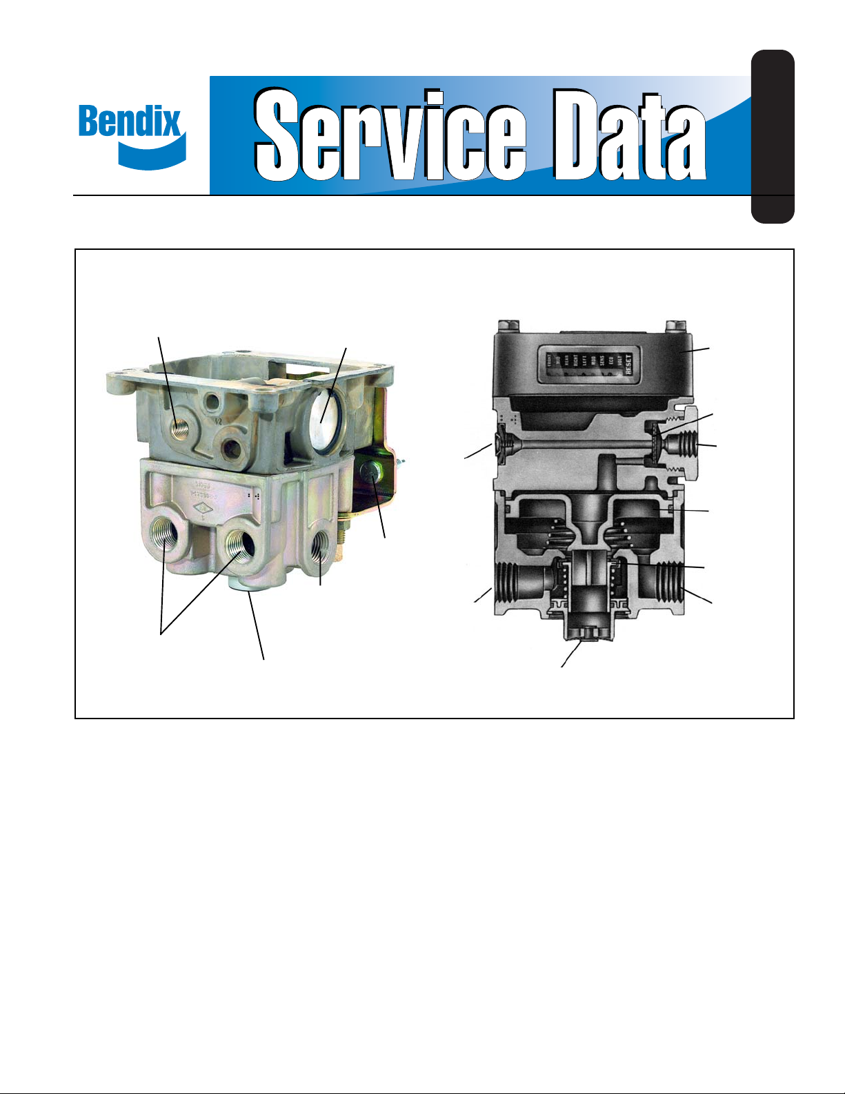
Bendix® AR-1™ AntiLock Relay Valve
SD-13-4795
QUICK EXHAUST
DELIVERY PORTS
™
AR-1
ANTILOCK
RELAY VALVE
SERVICE PORT
SUPPLY PORT
TYPICAL
MOUNTING
BRACKET
SUPPLY PORT
QUICK
EXHAUST
™
VALVE
AR-1
WITH ANTILOCK
CONTROLLER
ANTILOCK
CONTROLLER
QUICK/
EXHAUST DIA.
SERVICE
PORT
RELAY
PISTON
INLET/
EXHAUST
VALVE
DELIVERY
PORT
EXHAUST PORT
DESCRIPTION
The AR-1™ antilock relay valve (Figure 1) is a specialized
service brake relay valve. It is essentially an R-14™ relay
valve with a special cover that permits direct attachment of
an antilock controller. When combined with an antilock
controller the resulting assembly is referred to as a antilock
relay controller. For example when the AR-1™ antilock relay
valve is combined with the EC-30™ tractor antilock controller
the resulting assembly is referred to as a CR-30™ antilock
relay controller. While intended for use on antilock equipped
vehicles, the AR-1™ antilock relay valve functions solely as
a service brake relay and contains no electronics of its own.
In an air brake system, the AR-1™ valve serves as a relay
station to speed the application and release of the service
brakes. The valve is normally mounted in proximity to the
service actuators it serves. A mounting bracket furnished
EXHAUST PORT
FIGURE 1 - AR-1™ ANTILOCK RELAY VAL VE ASSEMBLY
with the valve permits either frame or cross member mounting.
All air connections on the AR-1™ valve are identified with
cast, embossed letters for ease of installation. The letter
identification and air line connections are shown below for
reference.
AR-1™ VALVE
AIR CONNECTION EMBOSSED IDENT.
Supply (to reservoir) SUP
Delivery (to brake actuator) DEL
Service (to brake valve rear service delivery) SE R
Like the R-14™ relay valve, the AR-1™ valve incorporates a
quick release valve adjacent to the service port which provides
for rapid exhaust of control air pressure from above the
1
Page 2
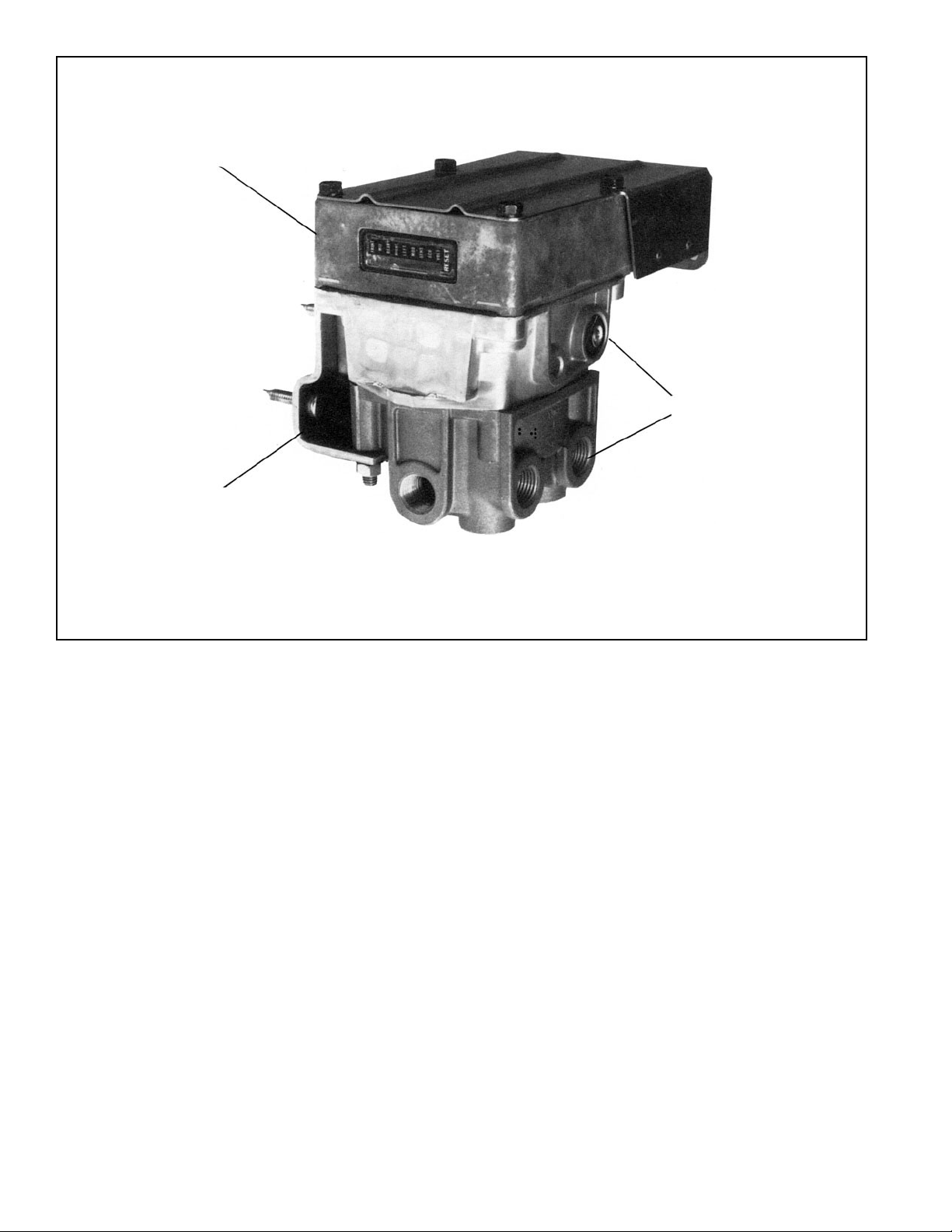
EC-15™ ANTILOCK
CONTROLLER
TYPICAL
MOUNTING
BRACKET
™
AR-1
ANTILOCK RELAY
FIGURE 2 - CR-15™ ANTILOCK RELAY CONTROLLER
relay piston. The standard AR-1™ valve is offered with a 4 psi
crack pressure however with the addition of a various springs
beneath the relay piston higher crack pressures are
possible.
The AR-1™ valve’s internal components are interchangeable
with the R-12™ and R-14™ relay valves therefore the same
maintenance kit is used to service all three valves.
OPERATION
BRAKE APPLICA TION
Brake application air enters the AR-1™ valve’s service port and
encounters the exhaust diaphragm which flexes in response
to the incoming air, sealing the exhaust passage in the cover .
Air flows around the exhaust diaphragm and moves through a
passage in the cover to the top of the relay piston. In response
to air pressure, the relay piston moves into contact with the
exhaust portion of the inlet and exhaust valve. With the exhaust
passage sealed, continued movement of the relay piston
unseats the inlet portion of the inlet and exhaust valve, allowing
supply air from the reservoir to flow out the AR-1™ valve’s delivery
ports to the antilock modulators and then to the brake
actuators. (Figure 3)
2
HOLDING-BALANCED
The air pressure being delivered to the antilock modulators
and brake actuators is also present beneath the relay piston.
When the air pressure above and below relay piston is
equal, the piston moves slightly allowing the inlet valve to
return to its seat. The exhaust valve remains closed. With
both the inlet and exhaust valves closed, air pressure in the
antilock modulators and brake actuators is held stable and
neither increases nor decreases. (Figure 4)
EXHAUST - BRAKE RELEASE
When the brake application is released, air pressure in the
service port of the AR-1™ valve returns to the foot brake valve
and is exhausted. Air , from above the relay piston, flows back
through the cover to the exhaust diaphragm. The diaphragm
flexes in response to the returning air, sealing the service port
and opening the exhaust in the cover. With the exhaust
diaphragm blocking the service port, returning air flows out the
open exhaust. As air pressure is reduced above the relay piston,
pressure beneath it lifts the piston away from the exhaust
valve and opens the exhaust passage. Air from the antilock
modulators and brake actuators returns to the AR-1™ valve
and flows out the open exhaust. (Figure 5)
Page 3
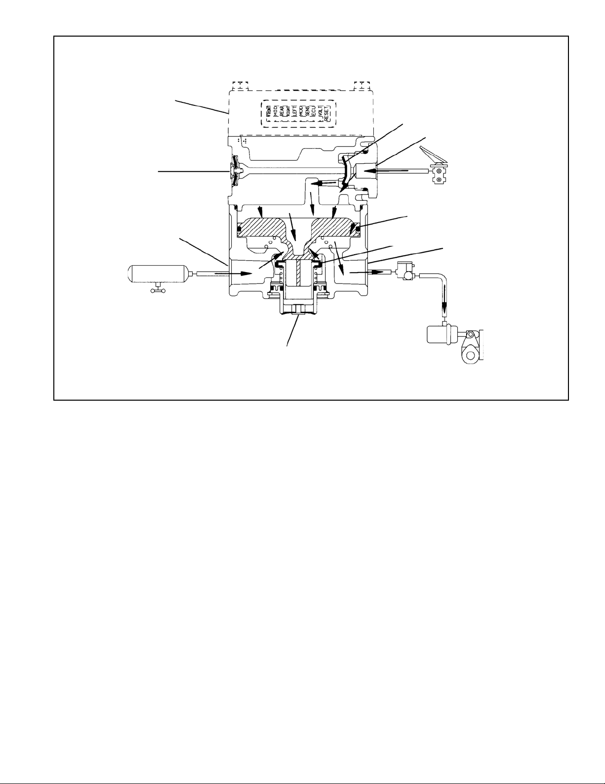
ANTILOCK
CONTROLLER
EXHAUST
QUICK EXHAUST DIA.
SERVICE PORT
RELAY PISTON
SUPPLY PORT
RESERVOIR
EXHAUST
FIGURE 3 - AR-1™ VAL VE BRAKE APPLICA TION
PREVENTIVE MAINTENANCE
Important: Review the warranty policy before performing
any intrusive maintenance procedures. An extended warranty
may be voided if intrusive maintenance is performed during
this period.
Because no two vehicles operate under identical conditions,
maintenance intervals will vary. Experience is a valuable guide
in determining the best maintenance interval for a vehicle.
INLET/EXH.
VALVE
ANTILOCK
MODULATOR
ACTUATOR
DELIVERY PORT
BRAKE
3. T est air line fittings for excessive leakage and tighten or
replace as necessary.
4. Perform the Leakage T est described in this manual.
EVERY YEAR, 100,000 MILES, OR 3,600
OPERA TING HOURS
1. Perform the Operation and Leakage T est s described in
this manual.
GENERAL
Perform the tests and inspections presented at the
prescribed intervals. If the AR-1™ valve fails to function as
described, or leakage is excessive, it should be repaired or
replaced with a new or genuine Bendix remanufactured
unit, available at any authorized parts outlet.
EVERY 3 MONTHS, 25,000 MILES OR 900
OPERA TING HOURS
1. Remove any accumulated contaminates and visually
inspect the exterior for excessive corrosion and physical
damage.
2. Inspect all air lines connected to the AR-1™ valve for
signs of wear or physical damage. Replace as necessary .
OPERATION & LEAKAGE TESTS
OPERA TING TEST
1. Apply and release the brakes several times and check
for prompt application and release at each wheel. If
prompt reaction is noted at some, but not all wheels,
test the AntiLock modulator between the AR-1™ valve
and the brake actuator for proper operation. If a “sluggish”
response is noted at all wheels, inspect for a kinked or
obstructed air line leading to or from the AR-1™ valve.
2. If a complete release of the brakes is noted at some, but
not all wheels, test the antilock modulator between the
AR-1™ valve and the brake actuator for proper operation.
If an incomplete release is noted at all wheels, inspect
for a kinked or obstructed air line leading to or from the
AR-1™ valve.
3
Page 4

ANTILOCK
CONTROLLER
EXHAUST
QUICK EXHAUST DIA.
SERVICE PORT
RELAY PISTON
SUPPLY PORT
RESERVOIR
EXHAUST
FIGURE 4 - AR-1™ V ALVE HOLDING - BALANCED
3. During brake release confirm that a slight “puff” of air
exits at the AR-1™ valve’s quick exhaust port in the cover .
Air exiting at this exhaust port indicates the AR-1™ valve
integral quick release is functioning.
LEAKAGE TESTS
1. Build the air system pressure to governor cut-out, apply
a soap solution to the exhaust port in body. The leakage
noted should not exceed a one inch bubble in less than
three (3) seconds.
2. Make and hold a full brake application and apply a soap
solution to the exhaust ports in the body and cover and
around the cover where it joins the body . The leakage
noted should not exceed a one inch bubble in less than
three (3) seconds at any exhaust port.
WARNING! PLEASE READ AND FOLLOW
THESE INSTRUCTIONS TO AVOID
PERSONAL INJURY OR DEATH:
When working on or around a vehicle, the following
general precautions should be observed at all times.
1. Park the vehicle on a level surface, apply the
parking brakes, and always block the wheels.
Always wear safety glasses.
4
INLET/EXH. VALVE
DELIVERY PORT
ANTILOCK
MODULATOR
BRAKE
ACTUATOR
2. Stop the engine and remove ignition key when
working under or around the vehicle. When
working in the engine compartment, the engine
should be shut off and the ignition key should be
removed. Where circumstances require that the
engine be in operation, EXTREME CAUTION should
be used to prevent personal injury resulting from
contact with moving, rotating, leaking, heated or
electrically charged components.
3. Do not attempt to install, remove, disassemble or
assemble a component until you have read and
thoroughly understand the recommended
procedures. Use only the proper tools and observe
all precautions pertaining to use of those tools.
4. If the work is being performed on the vehicle’s air
brake system, or any auxiliary pressurized air
systems, make certain to drain the air pressure
from all reservoirs before beginning ANY work on
the vehicle. If the vehicle is equipped with an
AD-IS™ air dryer system or a dryer reservoir module,
be sure to drain the purge reservoir.
5. Following the vehicle manufacturer’s
recommended procedures, deactivate the electrical
system in a manner that safely removes all electrical
power from the vehicle.
Page 5

ANTILOCK
CONTROLLER
EXHAUST
QUICK EXHAUST DIA.
SERVICE PORT
RELAY PISTON
SUPPLY PORT
RESERVOIR
EXHAUST
FIGURE 5 - AR-1™ VAL VE EXHAUST - BRAKE RELEASE
6. Never exceed manufacturer’s recommended
pressures.
7. Never connect or disconnect a hose or line
containing pressure; it may whip. Never remove a
component or plug unless you are certain all
system pressure has been depleted.
8. Use only genuine Bendix® replacement parts,
components and kits. Replacement hardware,
tubing, hose, fittings, etc. must be of equivalent
size, type and strength as original equipment and
be designed specifically for such applications and
systems.
9. Components with stripped threads or damaged
parts should be replaced rather than repaired. Do
not attempt repairs requiring machining or welding
unless specifically stated and approved by the
vehicle and component manufacturer.
10. Prior to returning the vehicle to service, make
certain all components and systems are restored to
their proper operating condition.
INLET/EXH. VALVE
DELIVERY PORT
ANTILOCK
MODULATOR
BRAKE
ACTUATOR
VALVE REMOVAL
1. Park the vehicle on a level surface and block the wheels
and/or hold the vehicle by means other than the air
brakes.
2. Drain the air pressure from all vehicle reservoirs.
3. Identify , mark or label all air lines and wiring cables and
their respective connections on the valve or antilock
controller to facilitate ease of installation.
4. Disconnect all air lines and wiring.
5. Remove the valve and controller assembly from the
vehicle.
VALVE INSTALLATION
1. Install all air line fittings and plugs making certain thread
sealing material does not enter the valve.
2. Install the assembled valve on the vehicle.
3. Reconnect all air lines and wiring cables to the valve and
controller assembly using the identification made during
VALVE REMOVAL step 3.
4. After installing the valve and controller assembly , test all
air fittings for excessive leakage and tighten as needed.
5
Page 6

1
ANTILOCK
CONTROLLER
2
23
24
15
25
11
13
11
19
16
18
17
13
12
22
26
21
20
14
5
MOUNTING
BRACKET
10
9
8
6
3
FIGURE 6 - AR-1™ ANTILOCK RELA Y V ALVE WITH CONTROLLER
6
7
4
Page 7

DISASSEMBLY
GENERAL
The following disassembly and assembly procedure is
presented for reference purposes only and presupposes
that the appropriate maintenance kit is on hand at the time
of disassembly. The instructions provided with the
maintenance kit should always be used in lieu of those
presented here. Refer to figure 6 throughout the disassembly
and assembly procedure.
CAUTION: The AR-1™ valve may be lightly clamped in a
bench vise during disassembly , however, over clamping will
cause damage to the valve and result in leakage and/or
malfunction. If a vise is to be used, position the valve so
that the jaws bear on the supply ports on opposing sides of
the valve’s body .
1. Remove all air fittings and plugs from the valve.
2. Mark the relationship of the antilock electronic controller
and valve cover to the body (5). Note the position of the
mounting bracket and mark the relationship of the bracket
to the valve body , cover, and antilock controller . Remove
and retain the four cap screws and lock washers (1) that
secure the controller to the cover (15), then carefully
remove the electronic controller without damaging its
gasket (2).
3. While holding the exhaust cover (4), remove and discard
the retaining ring (3) that secures it to the body (5).
4. Remove and discard the exhaust cover (4) along with
both o-rings (6 & 7).
5. Remove and discard the valve spring (8), valve retainer
(9), and the valve assembly (10) from the body (5).
6. Remove and retain the two cap screws (11) and lock
washers (12) that secure the cover (15) to the body (5).
Remove and retain the two bolts (13), lock washers (12),
and nuts (14) that secure the cover (15) and mounting
bracket to the valve body (5).
7. Separate the cover (15) and mounting bracket from the
body (5), then remove and discard the sealing ring (16).
Remove and retain the two cap screws and lockwashers
(26) that secure the bracket to the cover (15).
8. Remove and retain the relay piston (17) and relay piston
spring (19) from the body (5). NOTE: The relay piston
spring, item 19 is not used in all valves.
9. Remove and discard the o-ring (18) from the relay piston
(17).
10. Remove and retain the service port cap nut (20) from the
cover (15), then separate and discard the cap nut o-ring
(21) from the cap nut.
1 1. Remove and discard the quick exhaust diaphragm (22)
from the cover (15).
12.Remove the quick exhaust diaphragm retaining screw
(23), the diaphragm washer (24) and the diaphragm (25)
from the cover (15).
CLEANING & INSPECTION
1. Using mineral spirits or an equivalent solvent, clean and
thoroughly dry all metal parts.
2. Inspect the interior and exterior of all metal parts that
will be reused for severe corrosion, pitting and cracks.
Superficial corrosion and/or pitting on the exterior
portion of the body (5) and cover (15) is acceptable.
Replace the entire valve if the interior of the body or cover
exhibit signs of corrosion or pitting.
3. Inspect the bores of both the body (5) and cover (15) for
deep scuffing or gouges. Replace the entire valve if
either are found.
4. Make certain all air channels and exhaust passages in
the valve cover (15) are clear and free of obstruction.
5. Inspect the pipe threads in the body (5). Make certain
they are clean and free of thread sealant.
6. Wash all non-metallic components in a soap and water
solution making certain to rinse and dry thoroughly.
Inspect each non-metallic component for cracks, wear
or distortion. Replace the entire valve if these conditions
are found.
7. If the valve was equipped with a relay piston spring (19),
inspect it for signs of corrosion, pitting and cracks.
Replace as necessary .
8. Inspect all air line fittings for corrosion and replace as
necessary . Make certain to remove all old thread sealant
before reuse.
ASSEMBLY
1. Prior to assembly, lubricate all o-rings, seals, and pistons,
as well as body bores, using the lubricant provided with
the Bendix maintenance kit.
2. Install the valve retainer (9) on the inlet and exhaust valve
(10) so that the flange of the retainer (9) surrounds the
rubber portion of the valve. Install the inlet and exhaust
valve in the body (5).
3. Install the inlet and exhaust valve return spring (8) in the
body (5).
4. Install the large and small diameter o-rings (7 & 6) in the
exhaust cover (4), then install the exhaust cover in the
body (5) taking care not to damage the o-rings. Hold the
exhaust cover in place.
5. While depressing the exhaust cover (4), install the
retaining ring (3) in the body (5). Make certain the retainer
(3) is fully seated in its groove in the body .
6. If the AR-1™ valve was equipped with a relay piston return
spring (19), install the spring in the body , large diameter
first.
7
Page 8

7. Using lubricant to hold them in place, install sealing ring
(16) on the cover (15).
8. Install the o-ring (18) on the relay piston (17), then install
the piston in the body (5).
9. After noting the relationship marks made prior to
disassembly , assemble the cover (15) on the body (5)
and the mounting bracket on the body (5) and secure
the components together using the two cap screws (1 1)
and two bolts (13), lock washers (12), and nuts (14).
Torque the cover cap screws (11) and bolts (13) to
120-150 lb. in.
10.Install the two cap screws and lock washers (26) that
secure the bracket to the cover (15) and torque them to
180-220 lb. in.
11. After noting the relationship of marks made prior to
disassembly, attach the gasket (2) to the antilock
controller then secure the antilock controller on the cover
(15) using the four cap screws and lock washers (1).
T orque the cap screws to 50-80 lb. in.
12.Install all air line fittings and plugs making certain thread
sealing material does not enter the valve.
13.Install the CR-15 (AR-1™ valve with attached antilock
controller) on the vehicle and perform the Operation and
Leakage T est s before returning the vehicle to service.
8
BW1665 © 2004 Bendix Commercial Vehicle Systems LLC. All rights reserved. 6/2004 Printed in U.S.A.
 Loading...