

Page 1
®
Bendix® A-18™ Trailer ABS (Gen 4™ and Gen 5™ ABS)
GEN 4™ AND GEN 5™ ABS INTRODUCTION
This manual describes the Bendix® A-18™ trailer ABS
system and contains two primary sections:
• Installation
• Service
The Installation section provides the information required
for the proper installation of a FMVSS-121 compliant trailer
air brake systems that incorporate the Bendix Trailer ABS
system and complementary trailer components.
The Service section of the manual includes the information
necessary to properly maintain, troubleshoot and repair the
™
A-18
trailer ABS system.
Following the installation, service, and troubleshooting
procedures contained in this manual will produce a high
performance, long life, low maintenance antilock braking
system.
For assistance in your area call Bendix at 1-800-247-2725
or RoadRanger
®
at 1-800-826-4357.
Benefits of T railer ABS
ABS-controlled trailer braking ensures optimum vehicle
stability while minimizing the stopping distance. During
vehicle operation, the trailer ABS Electronic Control Unit
(ECU) continuously monitors all wheel speed sensors. Data
input from the wheel speed sensors allows the ECU to:
• Detect impending wheel lock.
• Maintain optimum wheel slip.
• Maximize overall braking effectiveness.
• Minimize tendencies for trailer swing out during hard
braking conditions.
Document Revision Level
This document is subject to revision.
For updates please visit www.bendix.com.
Power Requirements for ABS . . . . . . . . . . . . . . . . . . . 3
General Air Brake Requirements . . . . . . . . . . . . . . . . . 4
Brake Priority Options . . . . . . . . . . . . . . . . . . . . . . . . . 5
ABS Performance Characteristics . . . . . . . . . . . . . . . . 6
ABS Controlled Braking . . . . . . . . . . . . . . . . . . . . . . . . 6
ABS Component Function . . . . . . . . . . . . . . . . . . . . . . 6
Trailer ABS Configurations . . . . . . . . . . . . . . . . . . . . . 7
Sensor Placement . . . . . . . . . . . . . . . . . . . . . . . . . . . . 7
Trailer ABS Component Overview . . . . . . . . . . . . . . . . 9
Electronic Control Unit (ECU) . . . . . . . . . . . . . . . . . . 11
Relay Valve . . . . . . . . . . . . . . . . . . . . . . . . . . . . . . . . 13
Relay Valve Operation Modes . . . . . . . . . . . . . . . . . . 14
Installation . . . . . . . . . . . . . . . . . . . . . . . . . . . . . . . . . 15
Install the ECU/Relay V alve and
Stand Alone Relay Valve . . . . . . . . . . . . . . . . . . . . . 16
Install the Inline Power Connector . . . . . . . . . . . . . . . 17
Install the Main ABS Harness . . . . . . . . . . . . . . . . . . 17
Install the Trailer Mounted Warning Light . . . . . . . . . 18
End-Of-Line Diagnostics . . . . . . . . . . . . . . . . . . . . . . 23
Use of Hand Held Tool for Configuration . . . . . . . . . . 23
Troubleshooting and Fault Codes . . . . . . . . . . . . . . . 25
Test Equipment . . . . . . . . . . . . . . . . . . . . . . . . . . . . . 26
ServiceRanger PC Software . . . . . . . . . . . . . . . . . . . 27
ABS Valve Troubleshooting . . . . . . . . . . . . . . . . . . . . 28
Speed Sensor Troubleshooting . . . . . . . . . . . . . . . . . 29
Accessing Codes . . . . . . . . . . . . . . . . . . . . . . . . . . . . 30
Fault Code Charts . . . . . . . . . . . . . . . . . . . . . . . . . . . 31
Glossary . . . . . . . . . . . . . . . . . . . . . . . . . . . . . . . . . . 39
®
Bendix
is a registered trademark of Bendix Commercial
Vehicle Systems LLC.
®
Eaton
, RoadRanger®, and ServiceRanger® are registered
trademarks of Eaton Corporation.
SD-13-4757
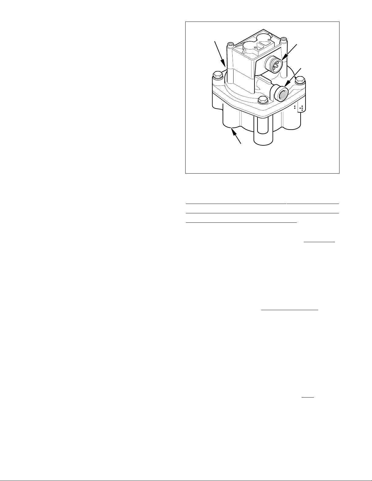
FIGURE 1 - ABS Controller Assemblies
Table of Contents
1
Page 2
Tractor and trailer ABS systems operate independently of
ABS
each other. Therefore, systems will work together properly
even if they are not supplied by the same manufacturer.
For information on disassembly , installation, and service of
related axle and brake components, refer to their individual
Bendix
®
Service Manuals.
For assistance in your area call Bendix at 1-800-247-2725
or RoadRanger
®
at 1-800-826-4357.
These ABS controllers and systems were originally
marketed under the Eaton
®
Brand name. For more
information, contact Bendix or refer to your local authorized
®
Bendix dealer, or RoadRanger
.
Power Requirements for ABS
Since March 1998 the trailer wiring systems provide two
sources of power for the antilock system.
The two power sources are:
1. Full-time power (when ignition is on) must be provided
by the tractor. This full-time power source may be
shared with other trailer circuits. The SAE J560 Blue
(AUX) circuit is commonly used as the full-time power
source. In other cases, a separate ISO3731 connector
is provided.
2. Brake light power is provided as a secondary source of
power in cases where an older tractor that does not
provide full-time power is used to operate an ABS
equipped trailer.
The industry requires that the tractor provide at least 10
amps at 12 volts at the trailer end of the SAE J560 or ISO
cable on all ABS power circuits. These specifications meet
TMC RP-137 and are consistent with SAE-2247.
There are no formal requirements. However , suppliers of
Trailer ABS have agreed to provide for proper antilock brake
operation down to a minimum of 8.5 volts (at which time
the warning lamp will activate). A new TMC RP
(Recommended Practice) is being developed which
recommends that trailer manufacturers provide a 1.0 volt
safety margin over the 8.5 volt minimum.
System current requirements will not exceed 0.5 amps per
control unit and three amps per valve.
™
A-18
trailer ABS system modulators have a nominal
resistance of 5.5 ohms and require approximately two amps
to operate. The control unit is designed to power warning
lamps with a typical current of 300mA for trailer mounted
warning lamps and 100mA for cab mounted warning lamps.
Administration (NHTSA). These requirements were
effective as of March 1, 1998.
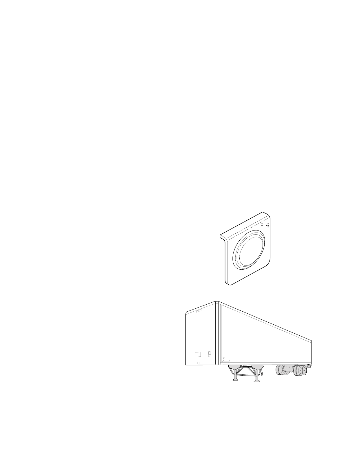
Location
The lamp mounting location shall be near the left side rear
of the trailer, no closer than 150 mm (5.9 inches) and not
more than 600 mm (23.6 inches) from the rear red side
marker indicator lamp. (Refer to Figure 22.) On a converter
dolly , the lamp mounting location shall be on a permanent
structure of the dolly at least 375 mm (14 inches) above
the road surface.
Color and Labeling
The malfunction indicator lamp must be yellow in color and
identified with the letters “ABS” to distinguish the lamp from
other yellow side markers. The letters may be on the lens,
on the lens housing, or on the trailer itself, near the lamp.
Intensity and Photometric Requirements
The external ABS malfunction indicator lamp must conform
to SAE-J592 JUN92. Trailers shall use a combination
clearance/side marker lamps marked with a “PC” or “P2”.
These lamps offer a widely diffused beam pattern
throughout a full 180-degree left and right range.
Trailer Mounted ABS Warning Light
Rules for the location, color, labeling, intensity and
photometrics for external ABS warning lamps have been
established by the National Highway Transportation Safety
2
Page 3

General Air Brake Requirements
Basic design requirements for trailer air brake systems are
set forth in FMVSS-121. FMVSS-121 covers requirements
for new construction. Once put into operation, the trailer’s
brake systems must be maintained in accord with the
following FHWA/OMC standards.
• FMCSR 393 - Covers required equipment
• FMCSR 396 - Covers inspection and repair
Air Timing Requirements
FMVSS-121 specifies the maximum times that are
permitted for application and release of brake chamber
pressure. Refer to Figure 2. ABS equipped trailers must
meet the same air timing requirements as prior , non-ABS
equipped trailers.
Reservoirs
Trailers must be equipped with air reservoirs that provide
a volume of air eight times that of the service brake
chambers.
For example: a type 30 air chamber has an effective surface
area of 30 sq. in. For short stroke type 30 air chambers,
the volume is typically 89 CID. For a typical two axle trailer,
the minimum required volume is therefore 2848 CID.
Reservoir size requirements for non-ABS and ABS
equipped systems are the same.
Air Consumption
During ABS activation there is a loss of reservoir pressure.
There are no specific requirements limiting air consumption
in the U.S. (In Europe Regulation R13 states specific
limitations). ABS manufacturers take air consumption into
account when developing and evaluating ABS control
algorithms. There has been no need to change reservoir
size requirements as a result of the ABS mandate.
VehicleClassification Application Time (seconds) Release Time (seconds)
From pedal
movement
for chambers
to reach 60 PSI
Pedal movement
to reach 60 PSI
at 50 cu. Res
at gladhand
From pedal
movement to
reach 5 PSI
(w/95 PSI initial
chamber pressure)
From movement
of the pedal until
50 cu. in. reservoir
reaches 5 PSI
(With 95 PSI initial
chamber pressure)
Tractors,Trailersand Buses .45 .35
.55
Towing Trailer .50 .50 1.001.00
Converter Dolly .55 .55 1.101.10
Single Trailer .60 — 1.20 —
Note:A50cubic inch reservoiris used tosimulate the towed trailer volume at the gladhands of towing units.
FIGURE 2 - Air Timing Requirements Chart
.75
3
Page 4
Brake Priority Options
In prior years, there were requirements for a protected
reservoir, separate from the main reservoir. The purpose
of the protected reservoir was to hold off the spring brakes
in the event of a failure of the service brake system.
In 1994, FMVSS-121 was revised to allow other approaches
to reservoir management. The protected reservoir
approach, although not required, is still acceptable.
Conventional trailers are designed for either:
• Spring Brake Priority or
• Service Brake Priority .
Spring Brake Priority–The advantage of spring brake
priority is that the parking brakes (spring brake) can be
released quickly to permit moving the trailer at start up.
However, spring brake priority systems have failure modes
under which the parking brakes can be released and the
vehicle operated without functional service brakes.
Service Brake Priority–The advantage of the service brake
priority system is that it assures that the service brakes
have adequate air pressure available to them before release
of the spring brakes is allowed. However, service brake
priority systems require more time to bring a vehicle up to
operational level.
The Bendix
both Spring Brake Priority and Service Brake Priority
systems and does not require special installation
procedures. A number of spring brake control valves are
suitable for meeting current requirements. Bendix offers
spring brake valves suitable for a range of applications.
®
A-18™ trailer ABS system is compatible with
TEV
1/4"
Supply Port
3/4"
Reservoir
Port
3/8"
Delivery Ports
FIGURE 3 - Spring Brake Control Valves
1/4"
Control
Port
Delivery
3/8"
Ports
3/4"
Reservoir
Port
3/8"
Delivery Ports
STEV
1/4" Supply Port
1/4"
Control
Port
3/8"
Delivery
Ports
4
Page 5
ABS PERFORMANCE CHARACTERISTICS
Routine Braking
During routine braking operations, there is no indication of
excessive wheel slip. The electronic control unit interprets
this condition as normal and ABS remains inactive.
ABS Controlled Braking
The control unit continuously monitors all available wheel
speed sensors. Data from the sensors is used to calculate
values of wheel speed and wheel slip and to make a best
estimate of the true vehicle speed. This data allows the
control unit to detect impending wheel lock and to hold the
wheel slip at an optimum value to maximize braking
effectiveness. The best possible vehicle stability is assured
while stopping distance is minimized.
Control is accomplished by operation of relay based
modulator valves. The control unit makes a new
assessment of conditions and updates the control signal
to the modulator valves at a rate of approximately 100 times
per second.
Under normal (non-ABS) conditions, trailer ABS relay valves
operate exactly like conventional mechanical relay valves.
(Refer to Figures 11 through 14.) During ABS operation,
the control unit operates the valves to override the supply
of air to the chambers. During an ABS release, supply air
is held off while the chambers are vented to the atmosphere.
In hold mode, supply air is blocked and chamber air is held
constant. When required, air is applied to the chamber at
a controlled rate by modulating the hold side of the valve.
The antilock system does not apply additional braking
power. Rather, it controls air pressure to release and hold
brake torque, thereby increasing a vehicle’s capacity for
quick, straight stops. With ABS installed, vehicle operation
is safer, resulting in improved protection of driver, cargo
and equipment.
System Designs
When operating on high traction surfaces with a loaded
vehicle, there is little difference between types of ABS
control. Performance differences appear when vehicles
are lightly loaded and operating on variable and poor traction
surfaces. Examples of poor traction surfaces are ice and
combinations of ice, snow and asphalt. Operating a vehicle
in a curve highlights differences in stability between various
systems.
ABS system designs provide compromises between stability
and stopping distance while addressing cost, complexity
and reliability issues.
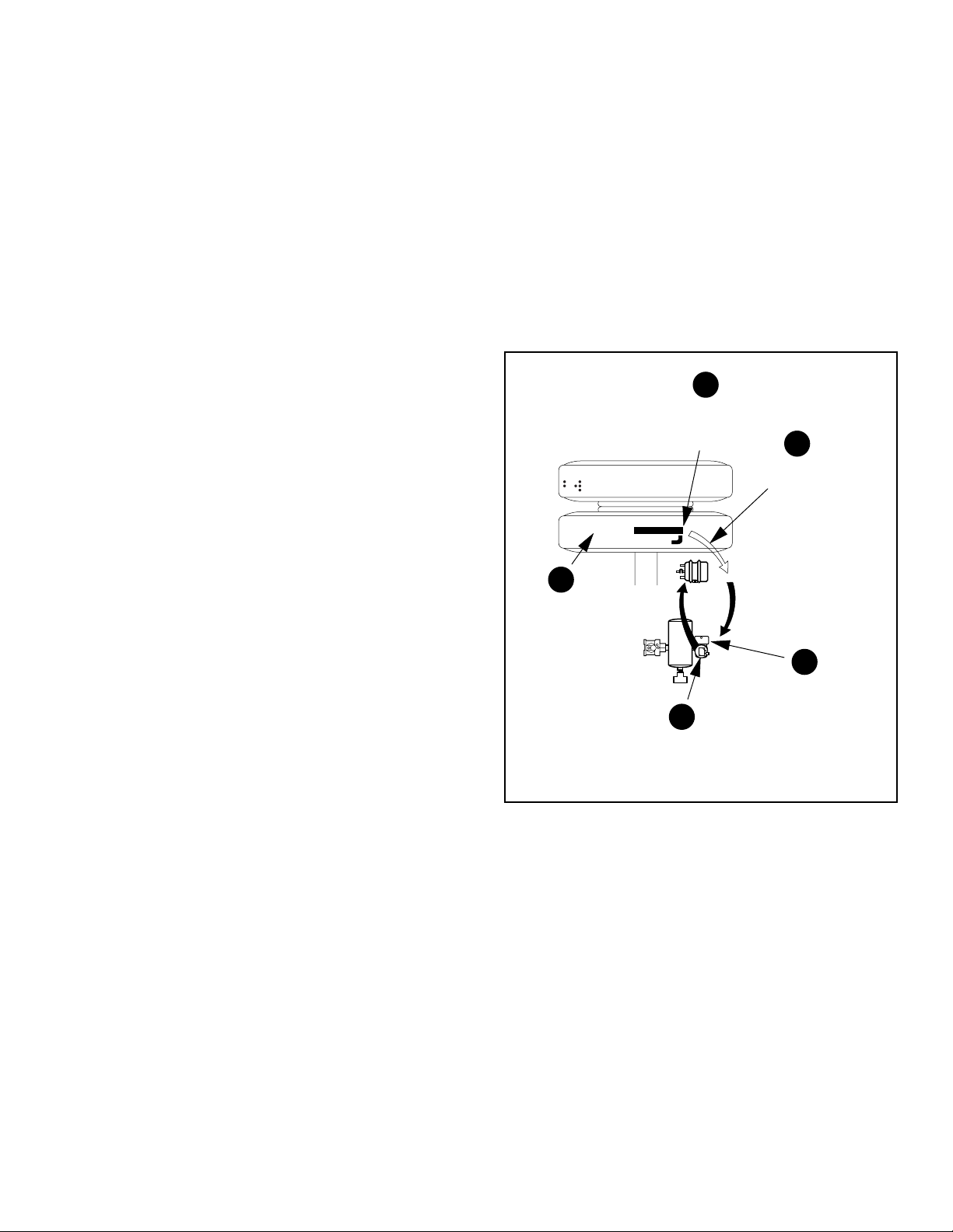
1
Speed sensors
monitor wheel
rotation
2
Speed signal
to ECU
5
Braking force
remains at
optimum level
Res.
4
Hold and release solenoids
control air pressure in the
brake chambers
3
ECU interprets
speed signals
and activates valves
ABS Component Function
Figure 4 shows an overview of the operation of the Bendix
A-18™ trailer ABS system.
Speed sensors (1) monitor wheel rotation and provide
information (2) on wheel rotation to the central electronic
control unit.
The Electronic Control Unit (3) receives the sensor signal,
interprets the pulse information, and constantly calculates
the relationship of speed, acceleration, and deceleration.
A control signal (4) is sent to the ABS relay valve (5), which
then controls the pressure to the air chambers.
FIGURE 4 - Overview of Trailer ABS Operation
®
5
Page 6

Independent Regulation
The most obvious control concept is independent wheel
control. In this case a single sensor controls a valve that
operates the brakes at one wheel site. Individual control
makes the best trade off between stability and stopping
distance. However, these systems have greater complexity
and higher cost with potentially lower reliability than less
complex systems. In many cases it is necessary to control
a single valve with inputs from two sensors.
Select Low
Select low systems monitor several wheels and controls
them with a single valve. Control is based on the wheel
that is at the lowest speed. Select low systems are very
stable but sacrifice stopping distance on split coefficient
surfaces. Modified select low systems incorporate a delay
before releasing to reduce the bias slightly away from the
low speed wheel.
Select High
Select high systems also monitor several wheels and control
them with a single valve. Control is based on the wheel
which is at the highest speed. Modified select high systems
activate a release before the low speed wheel becomes
severely locked. Select high systems generally have good
stopping distances at the expense of stability. These
systems may also have an increased risk of tire flat spotting.
Select Smart
Select Smart systems operate as select low systems when
there is little difference in traction between wheel control
sites. They operate as select high systems when there is a
significant difference in traction between sites. These
systems offer many of the advantages of individual control
systems while using a simpler design and fewer
components.
Bendix® A-18™ Trailer ABS Control Strategy
Select Smart is used for the most common applications.
Select low is used on the standard system 4S/2M Axle
Control configuration and is available as an option on the
basic system.
TRAILER ABS CONFIGURATIONS
Application Recommendations
Refer to the chart on page 8 to determine a recommended
ABS installation for your application.
Basic System (2S/1M)
The basic system includes two speed sensors and one
modulator valve for direct control of one axle and indirect
control of an additional axle. Other features of the basic
system include one ECU connector and a single-pin
diagnostic lead.
Standard System (2S/1M, 2S/2M and 4S/2M)
Bendix’s standard systems offer either two or four speed
sensors and up to two modulator valves. Standard systems
can directly control one or two axles and allow full
diagnostics via J1587. The standard system may be
configured in one of four ways to function as follows:
• 2S/1M—This configuration uses two sensors and one
modulator valve to directly control one axle and indirectly
control an additional axle.
• 2S/2M—This configuration uses two speed sensors and
two modulator valves for direct control of one axle and
indirect control of up to three additional axles.
• 4S/2M—This configuration uses four speed sensors
and two modulator valves for direct control of two axles
and indirect control of up to two additional axles.
• 4S/2M Axle Control—Special configuration for full
trailers and widely spaced axles. This configuration
uses the select low strategy .
Sensor Placement
When more than one wheel is controlled by a single valve,
sensors should be mounted at the axle which tends to lock
first. For spring suspensions this is usually the forward
axle. For air suspensions this is usually the rear most axle.
Lift Axles
• Gen-4™ ABS: Sensor inputs “C” and “D” of the control
unit may be used for lift axle wheel speed sensing.
• Gen-5
™
ABS: Direct lif t axle control is not available. Use
indirect control.
Reading Configuration Codes
On Basic systems, the jumper method must be used to
access the configuration. On Standard systems, access
to configuration information can be achieved by any of the
three methods:
• ServiceRanger diagnostic software on a PC
• Hand-held tester
• Jumper method.
For more information on accessing configuration codes,
refer to Accessing Codes on p age 30.
6
Page 7
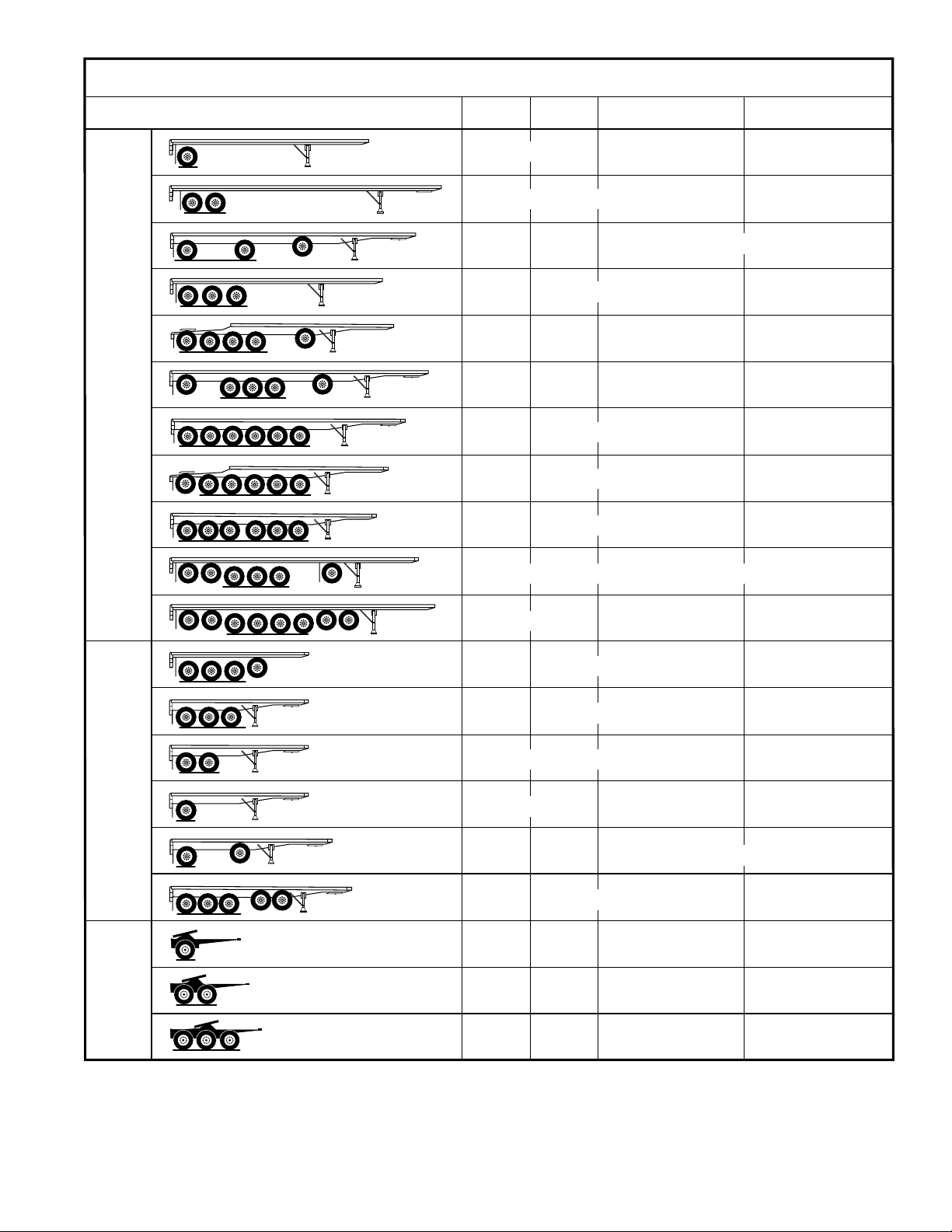
SystemApplication Chart
Semi
Trailer
or
1st
Trailer
TrailerType
2S/1M 2S/2M
or
(1) (1)
or or
(1) (1) (1)
4S/2M Side Control
or
(1)
or
(2)
or
(2)
(2)
or
(1)
(1)(1)
(1)
(2)
(2)
(2)
4S/2MAxle Control
or
(1)
1st
2nd
or
3rd
Trailer
Trailer
Dolly
orand
(1)(2)
and
(1)(2)
(1) (1)
or
(1) (1)
or
or or
(1) (1) (1)
or
(1) (1)
(2)
(1)
(2)
or
(2)
(1)
(1)
or
or
(2)
(1)
FIGURE 5 - System Application Chart
(1)
7
Page 8

Trailer ABS Component Overview
Bendix® A-18™ trailer ABS system includes the following
components:
• Electronic Control Unit (ECU): The ECU monitors
wheel speeds and controls the trailer ABS valves. It
also diagnoses ABS malfunctions and stores failurespecific fault codes. The ECU is usually attached to a
relay valve with a mounting bracket. The ECU may
also be directly frame mounted. One ECU can monitor
either two or four speed sensors and control either one
or two relay valves. If necessary more than one ECU
may be used on a single trailer.
• Relay Valve: This component regulates brake chamber
air pressure. It houses the hold and release solenoids.
Each relay valve can control either two or four brake
chambers on an ABS equipped trailer. A relay valve
can have the ECU mounted to it (valve A in the
installation diagrams) or be a stand alone relay valve
(valve B in the installation diagrams) that is controlled
remotely by the ECU mounted on valve A.
• Trailer Mounted ABS Warning Lamp: This indicator
lamp, located on the “Road Side” near the rear of the
trailer, warns the driver of ABS malfunctions (steady
“ON”). It is also capable of blinking diagnostic fault
codes.
• Cab Mounted ABS Warning Lamp: This indicator
lamp, located on the driver instrument panel, also warns
the driver of ABS malfunctions. It is not capable of
blinking diagnostic fault codes.
• Wheel End Speed Sensor and Tone Wheel: Single
point variable reluctance (magnetic) sensor that
generates an alternating current signal in response to
the movement of teeth on a tone wheel. The signal is
interpreted by the ECU to monitor wheel speed.
• Diagnostic Port Connector: The diagnostic port
connector is an industry standard connector which is
used to provide a connection to the J1587 diagnostic
link. This connector also provides power and ground
for diagnostic test equipment.
• Gladhand: The gladhands used on the ABS system
are the same as those used on non-ABS trailers.
• Seven Way Main Electrical Connector: The seven
way receptacle is the same as those used on non-ABS
systems. This receptacle provides full-time power,
backup power via the brake light switch and ground for
the ABS electrical system.
• Optional ISO 3731 connector: This is a 7-pin
connector similar to the J560 connector. The most
noticeable difference is that the ground terminal has a
gender opposite that of the other terminals. The primary
use for ISO 3731 is for the lighting connections on
European trailers. However, this connector is used to
provide interface to trailer ABS in some U.S.
applications. (In Europe another connector designated
as ISO 7638 is used to provide interface to the trailer
braking system.)
8
Page 9
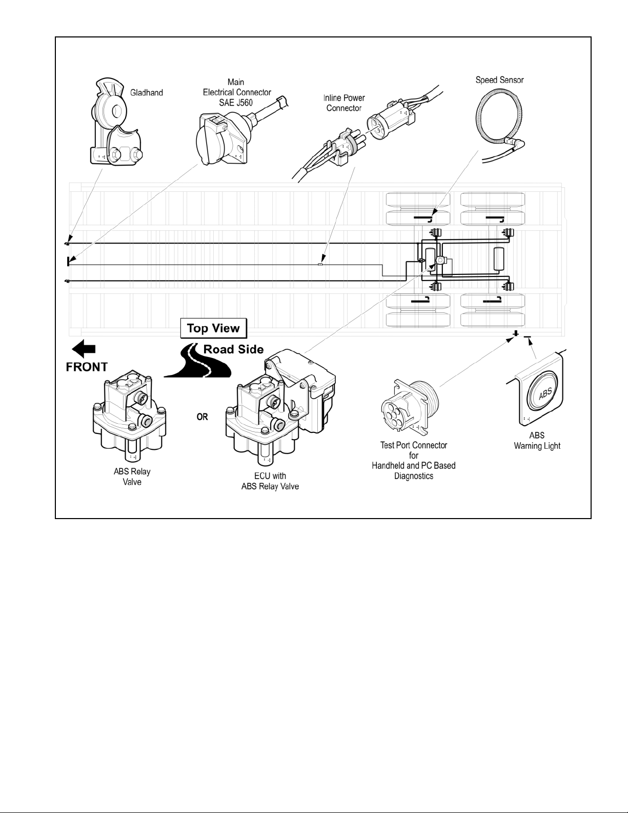
FIGURE 6 - ABS Trailer Components
9
Page 10
Electronic Control Unit (ECU)
The Bendix® A-18™ ECU is the trailer ABS control center.
Identification
Identification information for the ECU is located on the
connector pinout label (refer to Figure 7). The label is
located under the ECU cover. Refer to the label for the:
• Part Number
• Serial Number
• Date Code.
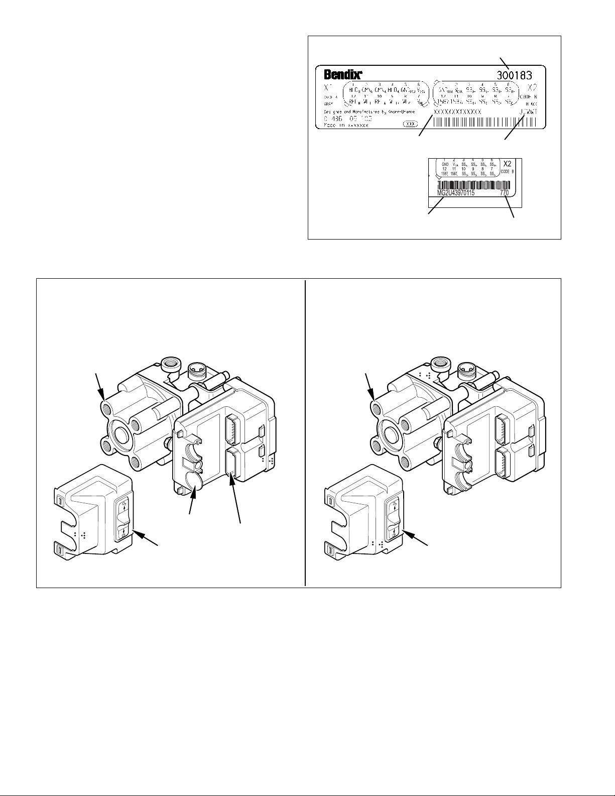
Depending on configuration, the A-18
ECUs may be equipped with either one connector (basic
system) or two connectors (standard system). Refer to
Figure 8.
BASIC STANDARD
™
trailer ABS system
Bendix Part Number
Basic System
Serial Number
Standard System
Serial Number
FIGURE 7 - Electronic Control Unit Identification Tags
Date Code
Date Code
Relay Valve
Plug
ECU Cover
FIGURE 8 - Trailer ABS ECU Configurations
Relay Valve
Blank
Connector
ECU Cover
10
Page 11
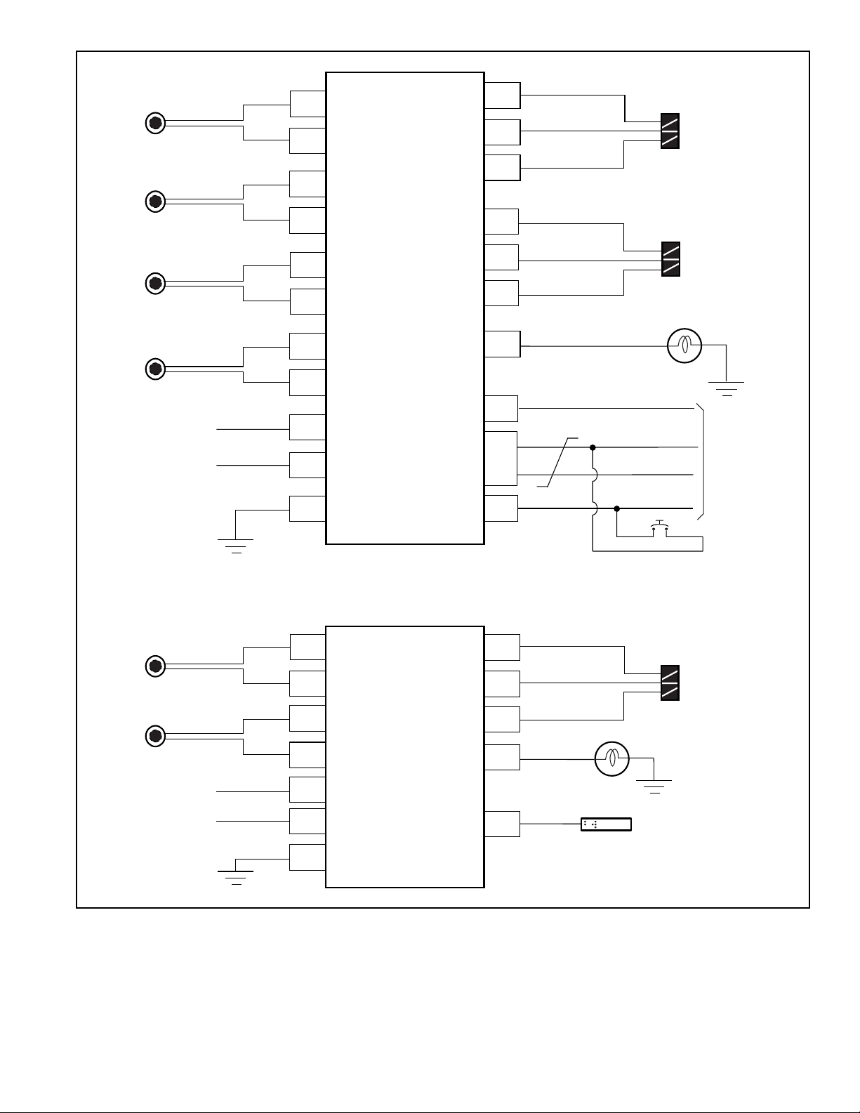
Inputs
Outputs
SensorA
Sensor B
Sensor C
Sensor D
Brake Light Power
Full Time Power
+
X2-4
-
X2-3
+
X2-6
-
X2-5
+
X2-8
-
X2-7
Standard
Trailer
ECU
(2 Connectors)
+
X2-10
-
X2-9
X1-7
X1-6
X1-5
X1-10
X1-3
X1-4
X1-12
X1-2
X1-1
X1-9
X2-2
X2-11
X2-12
X2-1
Common
Hold
Release
Common
Hold
ValveA
ValveB
J1587+
J1587 Gnd
TrailerMounted
WarningLight
J1587
Diagnostic Link
Diagnostic
Switch
Inputs
SensorA
Sensor B
Brake Light Power
Full Time Power
FIGURE 9 - Standard and Basic ECU Block Diagrams
+
X1-1
-
X1-2
+
X1-12
-
X1-11
X1-7
X1-6
X1-5
Trailer
(1 Connector)
Basic
ECU
Outputs
X1-10
X1-3
X1-4
X1-8
X1-9
Release
ValveA
Common
Hold
TrailerMounted
WarningLight
Diagnostic Plug
11
Page 12
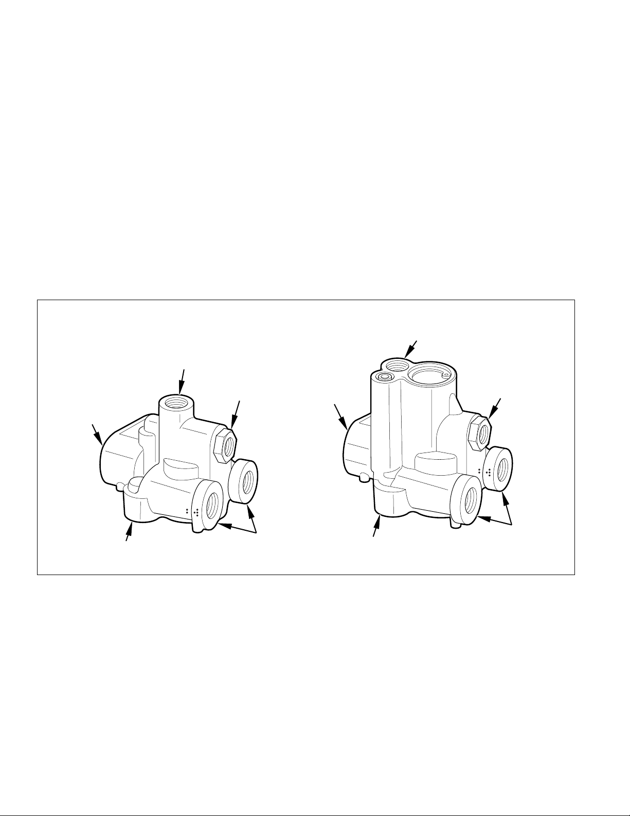
Relay Valve
The trailer ABS relay valve controls air pressure to individual
brake assemblies, and functions as a standard relay valve
when there are no ABS control signals. Depending on the
particular ABS configuration, a system may utilize one or
two relay valves. See Figure 10.
Each relay valve contains two solenoids for air control. The
hold solenoid maintains air pressure; the release solenoid
removes pressure from the brake. The Electronic Control
Unit signals the relay valve(s) for air hold and release by
activating the appropriate solenoid.
Each relay valve has a three-pin terminal for connection to
the Electronic Control Unit.
Delivery Ports
Both 2-port and 4-port versions of the relay valve are
available. These are all tapped for 3/8 NPT fittings.
Crack Pressure
St andard valves are available with 4.0 PSI ±0.5 PSI crack
pressure. Other crack pressures can be provided. For
example, 6.0 PSI valves may be used with wedge brakes.
Bracket, Valve, ECU combinations
Various combinations of mounting brackets, ECUs and
valves are available preassembled to facilitate system
installation on a variety of vehicles. Refer to the Bendix
A-18™ trailer ABS Illustrated Parts List for further
information.
Port Orientation
If necessary , the control and supply ports of the valve can
be reoriented with respect to each other. Remove the four
assembly bolts. Rotate top with respect to bottom as
required. Use care to maintain cleanliness of valve interior .
Retorque bolts to 10.0 lb-ft (13.6 N•m). Do not exceed
12.0 lb-ft (16.3 N•m).
Pipe Fitting Torques
Refer to the following torque specifications when installing
pipe nipples. Torques are for NPT threads with thread
sealant applied. Do not use thread tape. Contamination
by thread tape can cause component failure.
Tighten pipe nipples as follows:
• With Thread Sealant - Finger tight plus 1 1/2 turns
• Without Thread Sealant - Finger tight plus 2 turns
Clamping
A fixture may be necessary to hold the relay valve when
reorienting ports or when attaching fittings. If a vise is used,
there is a potential danger of distorting the barrel and piston
within the valve rendering the valve inoperative. It is
recommended that a fixture be used that avoids the
potential for stressing the valve.
3/4" Supply Port
Out
(3/8" Delivery Port to
Brake Chamber)
Figure 10 - Relay Valve
Three-Pin
ECU Connector
3/8" Control Port
WARNING! PLEASE READ AND FOLLOW
THESE INSTRUCTIONS TO AVOID
PERSONAL INJURY OR DEATH:
®
When working on or around a vehicle, the following
general precautions should be observed at all times.
1. Park the vehicle on a level surface, apply the
parking brakes, and always block the wheels.
Always wear safety glasses.
2. Stop the engine and remove ignition key when
working under or around the vehicle. When
working in the engine compartment, the engine
should be shut off and the ignition key should be
removed. Where circumstances require that the
engine be in operation, EXTREME CAUTION should
be used to prevent personal injury resulting from
contact with moving, rotating, leaking, heated or
electrically charged components.
3. Do not attempt to install, remove, disassemble or
assemble a component until you have read and
thoroughly understand the recommended
procedures. Use only the proper tools and observe
all precautions pertaining to use of those tools.
4. If the work is being performed on the vehicle’s air
brake system, or any auxiliary pressurized air
systems, make certain to drain the air pressure
from all reservoirs before beginning ANY work on
the vehicle. If the vehicle is equipped with an
AD-IS™ air dryer system or a dryer reservoir module,
be sure to drain the purge reservoir.
5. Following the vehicle manufacturer’s
recommended procedures, deactivate the electrical
system in a manner that safely removes all
electrical power from the vehicle.
12
Page 13

6. Never exceed manufacturer’s recommended
pressures.
7. Never connect or disconnect a hose or line
containing pressure; it may whip. Never remove a
component or plug unless you are certain all
system pressure has been depleted.
8. Use only genuine Bendix® replacement parts,
components and kits. Replacement hardware,
tubing, hose, fittings, etc. must be of equivalent
size, type and strength as original equipment and
be designed specifically for such applications and
systems.
9. Components with stripped threads or damaged
part s should be replaced rather than rep aired. Do
not attempt repairs requiring machining or welding
unless specifically stated and approved by the
vehicle and component manufacturer.
10. Prior to returning the vehicle to service, make
certain all components and systems are restored
to their proper operating condition.
Hold
Solenoid
Release
Solenoid
Relay Valve Operation Modes
1. Apply–Treadle pressure is applied to the top of the
piston. The sleeve is depressed until the outlet pressure
matches the pressure at the top of the piston.
2. Normal Release–Pressure at the top of the piston is
vented through the treadle valve. The sleeve rises to
block the inlet while allowing the chamber air to exhaust
through the center of the sleeve.
3. ABS Hold–Hold solenoid blocks treadle pressure. The
piston stabilizes, holding the chamber pressure at the
same level as that which is above the piston.
4. ABS Release–The release solenoid vents air at the top
of the piston while blocking treadle pressure. The sleeve
rises to block the inlet while allowing the chamber air to
exhaust through the center of the sleeve.
Control
Sleeve
Outlet
FIGURE 11 - Normal Apply and ABS Apply
Control
Piston
Supply
Control
Supply
Outlet Exhaust
FIGURE 12 - Normal Release
Control
Outlet Exhaust
FIGURE 13 - ABS Hold
Supply
Supply
Outlet Exhaust
FIGURE 14 - ABS Release
13
Page 14

Installation
Installation of the Bendix® A-18™ trailer ABS system is similar
from one configuration to another. All systems use the same
speed sensors and valves. The differences are in
placement and quantity and the type of ECU, either standard
or basic. Refer to the following general component
instructions and to the wiring and plumbing diagrams for
specific system configuration.
Suggested Order Of Installation
Following is a suggested order of installation of the A-18
trailer ABS.
1. Install Wheel Speed Sensors (often part of a dressed
axle).
2. Install Relay V alve(s)/ECU assembly .
3. Install the Power Cable, but do not apply power until
the installation is complete.
4. Route and connect the main ABS Harness.
5. Install the Diagnostic Port Connector .
6. Install the trailer-mounted ABS Warning Lamp.
7. Perform the End-of-Line Checkout.
Install the Wheel Speed Sensors and Sensor
Friction Sleeves
Refer to the appropriate diagram for your system and locate
the wheel speed sensors. Refer to Figures 23-26.
1. Install the sensor friction sleeve with the flange stops
towards the inboard side of the vehicle.
2. Apply high-temperature silicon-based grease to the
body of the speed sensor.
3. Push the speed sensor completely into sensor friction
™
sleeve by hand until it stops against the tone ring. The
speed sensor is properly installed and adjusted when it
is touching the tone ring. Allowable TIR for the tone
ring is 0.008 inches.
NOTE: The speed sensor must be able to slide freely in
and out of the sensor friction sleeve bore. Operating the
vehicle with seized components will damage the speed
sensor and the tone ring.
4. Route the cable to the frame. Use tie wraps as required
to restrain cable. Use care not to stress sensor cables.
5. Connect sensor cable to harness and install fasteners
to hold the sensor cable in position.
Push
Sensor
FIGURE 15 - Speed Sensor Installation
Sensor
Friction Sleeve
FIGURE 16 - Wheel Speed Sensor Components
ABS
Sensor
Bushing
14
Page 15

Install the ECU/Relay Valve and Stand Alone
Relay Valve
In all installations, the ECU/Relay V alve assembly appears
as Relay V alve “A” in the diagrams. The S tand Alone Relay
Valve is identical to the ECU/Relay Valve except it does
not have the ECU and ECU mounting bracket. The relay
valves may be installed on the reservoirs or a frame
member.
The Stand Alone Relay Valve is the second relay valve in
systems with two relay valves and is labeled Relay Valve
“B” in the diagrams.
Pipe Fitting Torques
Refer to the following torque specifications when installing
pipe nipples. Torques are for NPT threads with thread
sealant applied. Do not use thread tape. Contamination
by thread tape can cause component failure.
Tighten pipe nipples as follows:
• With Thread Sealant - Finger tight plus 1 1/2 turns
• Without Thread Sealant - Finger tight plus 2 turns
Leak and Performance Test
1. Park vehicle on level surface and block wheels.
2. Make and hold brake application. No audible air leaks
are permitted.
3. Release parking brake and fully charge the air system
(governor cut out point).
4. Turn engine OFF . Apply the service brake several times,
then hold and check for prompt brake air chamber
application and release at all wheels.
5. Apply brake, then hold. Coat outside of relay valve with
a soap solution. No leakage is permitted.
NOTE: If a sluggish response is noted at all wheels, inspect
for kinked or obstructed air line leading to or from valve.
6. Increase system air pressure to governor cut-off. With
brakes released, coat exhaust port of relay valve with a
soap solution. Leakage of a 1” bubble in 5 seconds is
permissible.
7. Depress foot valve and keep depressed. Coat exhaust
port with a soap solution. Leakage of a 1” bubble in 3
seconds is permissible.
3/4" Heavy Wall
Steel Pipe Nipple
Reservoir Tank
Relay Valve
FIGURE 17- Tank Mounted ECU/Relay Valve
Frame
Member
ECU
Relay Valve
ECU
FIGURE 18 - Frame Mounted Relay Valve
15
Page 16

Install the Inline Power Connector
The inline power connector is on the end of the main ABS
harness and connects the ABS system to the trailer
electrical system.
To
To
ECU/
Modulator
Valve
FIGURE 19 - Inline Power Connector
J560
Nose
Box
Trailer
Side
Power
Cable
ECU Side
Bayonett Connector
at Relay Valve
(Up to 2)
5 Pin
Weatherpack
Install the Main ABS Harness
1. Remove power from the trailer.
2. Unlock the ECU cover and remove.
3. Install the ECU connectors as follows:
Standard: Plug the grey harness connector into the
ECU connector labeled “X1”. The connector is keyed
and can only fit in one direction. Plug the black harness
connector into the ECU connector labeled “X2”. This
connector is also keyed.
Basic: Plug the green harness connector into the ECU
connector labeled “X1”. This connector is also keyed
and is the only connector on the ECU.
4. Install the ECU cover by first engaging the alignment
tabs and then hinging the cover closed, ensuring that
the convoluted tubing is captured in the strain relief slots.
Slide the cover lock to the locked position. An optional
tie wrap may be used to lock the cover in place.
5. Route harness to designated locations. Make sure that
the harness is properly routed and secured to prevent
damage to the harness.
BASICSTANDARD
One Bayonett Connector
at Relay Valve
J560
Diagnostic
5 Pin
Weatherpack
6" Pigtail
Deutsch
Male
Bayonet
Warning
Light
Chassis
Ground
FIGURE 20 - Standard and Basic ABS Harnesses
ABS ABS
Hd-10
Diagnostic
Speed
Sensor
(2 or 4)
Warning
Light
6" Pigtail
Male
Bayonet
Two
Speed
Sensors
Road SideRoad Side
Chassis
Ground
16
Page 17

To Frame
Diagnostic
Port
Diagnostic
Port Bracket
FIGURE 21 - Diagnostic Port Installation (Standard)
Install the Diagnostic Port (Standard System)
On standard systems, the diagnostic port is installed on
the road side of the trailer, on the frame forward of the
trailer axle(s). To install the diagnostics port, bolt or weld
the diagnostic port bracket to the trailer frame.
Install the Trailer Mounted Warning Light
The warning light is mounted on the road side of the trailer,
forward of the marker light according to the following
drawing.
ABS
5.9"
(160mm)
ABS
Warning
Lamp
23.6"
(600mm)
Rear
of
Trailer
Rear
Side Marker
FIGURE 22 - Warning Light Location
17
Page 18

2S-1M Electrical Configuration(Top View)
Front
J560 Connector
Power Cable
ECU Side
Trailer
Side
Parts List
Description Quantity
ECU/Relay Valve 1
Sensor/Diagnostics Cable 1
Valve/PowerCable 1
Sensors —0.4mCable 2
Sensor FrictionSleeve 2
WarningLampConnector
Warning
Light Side
Harness Side
Diagnostic Port
(Shown with
Extension)
Top View
Road Side
Wheel Sensor Speed Sensor
ECU
Side
Wheel
Side
Sensor B
SensorA
ABS WarningLampECU
Modulator
Valve
ABS
2S-1MAir System Configuration (Top View)
Key
3/8" O.D.NylonTubing
3/8" O.D.NylonTubing (Alt. 1/2" O. D.)
3/8" I.D.Hose
Gladhand
Service (Control)Line
Front
Supply Line
Gladhand
Top View
Road Side
FIGURE 23 - Typical 2S-1M ABS Electrical and Air System
TEV orSTEV
Spring Brake
Control
ABS
ECU
3/4" HeavyWall
Steel PipeNipple
Res. Res.
ABS
Relay
Valve
Service
Brake
Chamber
Emergency
Brake
Chamber
18
Page 19

2S-2M Electrical Configuration (Top View)
J560 Connector
Power Cable
Diagnostic Port
Wheel Sensor
Speed Sensor
Front
WarningLampConnector
Warning
Light Side
ECU Side
Trailer
Side
Parts List
Description Quantity
ECU/Relay Valve 1
StandAloneRelay Valve 1
Sensor/Diagnostic Cable 1
Valve/PowerCable 1
Sensors —0.4mCable 2
Sensor FrictionSleeve 2
Harness Side
Top View
Road Side
Relay
ValveA
ECU
Side
Wheel
Side
Stand
Alone
Relay
ValveB
Sensor B
SensorA
ABS WarningLampECU
ABS
2S-2MAirSystem Configuration (TopView)
Key
3/8" O.D.NylonTubing
3/8" O.D.NylonTubing (Alt. 1/2" O.D.)
3/8" I.D.Hose
Gladhand
Service (Control)Line
Front
Gladhand
Supply Line
Spring BrakeControl
Top View
Road Side
FIGURE 24 - Typical 2S-2M ABS Electrical and Air System
TEV orSTEV
Service BrakeChamber
ABS
ECU
Relay
Valve
Res. Res.
B
Relay Valve A
Emergency BrakeChamber
19
Page 20

4S-2M Side ControlElectrical Configuration (Top View)
J560 Connector
Power Cable
Diagnostic Port
Wheel Sensor
Speed Sensor
Front
WarningLampConnector
Warning
Light Side
ECU Side
Trailer
Side
Parts List
Description Quantity
ECU/Relay Valve 1
StandAloneRelay Valve 1
Sensor/Diagnostic Cable 1
Valve/PowerCable 1
Sensors — 0.4mCable 4
Sensor Friction Sleeve 4
Harness Side
Top View
Road Side
Relay
ValveA
SensorA
Sensor B
ECU
Side
Wheel
Side
Stand
Alone
Relay
ValveB
Sensor D
Sensor C
ABS WarningLampECU
ABS
4S-2M Side ControlAirSystem Configuration (TopView)
Key
3/8" O. D.NylonTubing
3/8" O. D.NylonTubing (Alt. 1/2" O. D.)
3/8" I. D.Hose
Gladhand
Service (Control) Line
Front
Gladhand
Supply Line
TEV or STEV
Spring Brake Control
Top View
Road Side
FIGURE 25 - Typical 4S-2M Side Control ABS Electrical and Air System (Top View)
Service Brake Chamber
ABS
ECU
Relay
Valve
Res. Res.
B
Relay ValveA
Emergency Brake Chamber
20
Page 21

4S-2MAxle Control ElectricalConfiguration (TopView)
J560 Connector
Power Cable
Diagnostic Port
Wheel Sensor
Speed Sensor
Front
WarningLampConnector
Warning
Light Side
ECU Side
Trailer
Side
Parts List
Description Quantity
ECU/Relay Valve 1
StandAloneRelayValve 1
Sensor/Diagnostic Cable 1
Valve/PowerCable 1
Sensors — 0.4mCable 4
Sensor Friction Sleeve 4
LiftAxle
(Gen-4 Only)
Top View
Harness Side
Road Side
Sensor C
Stand
Alone
Relay
ValveB
ECU
Side
Wheel
Side
Sensor D
Sensor B
SensorA
ABS WarningLampECU
Relay
ValveA
ABS
4S-2MAxle Control Air System Configuration (TopView)
LiftAxle
(Gen-4 Only)
Gladhand
Service (Control) Line
Front
Gladhand
Top View
Supply Line
Service Brake Chamber
Road Side
ABS Relay B
(No ECU)
Key
3/8" O. D.NylonTubing
3/8" O. D.NylonTubing (Alt. 1/2" O. D.)
3/8" I. D.Hose
ABS
Res. Res. Res.
Emergency Brake Chamber
Relay
A
TEV or STEV
Spring Brake Control
FIGURE 26 - Typical 4S-2M Axle Control ABS Electrical and Air System (Tank Mount Shown) (Top View)
21
Page 22

End-Of-Line Diagnostics
Automatic System Configuration:
The Bendix® A-18™ trailer ABS system automatically
configures itself to any valid ABS system installed on the
trailer. The automatic configuration process occurs each
time the system receives power at the permanent power
input. In most cases this ECU input is connected to the
SAE J560 connector AUX connection. During the automatic
configuration process, the ECU will only configure upwards.
That is, it will add but not subtract components from its
configuration.
The configuration can be checked by using the hand held
diagnostic tool or by activating the blink code as described
in the “End-of-Line Checkout Procedure” listed below.
Compare the two part blink code with the chart. Part 1 of
the blink code is the current system configuration.
Use of Hand Held Tool for Configuration
The system always configures upwards depending on the
components which are found connected to it. If a lower
configuration is desired, a hand held tester must be used
to reconfigure the system.
End-of-Line Checkout Procedure (Basic):
Note: It is not possible to miswire the components on a
2S/1M (Basic) system. Therefore, the checkout procedure
does not require the use of a hand-held tester.
1. Apply power to ECU (do not use a battery charger as a
power source).
2. Verify that the ABS warning light turns OFF and remains
OFF after the bulb test.
Note: If there was a past speed sensor fault in the
system, the warning light will not turn OFF until the trailer
has been operated at a speed sufficiently high to be read
at the ECU, typically 3 to 5 mph.
End-of-Line Checkout Procedure (Standard):
Note: For 2S/1M systems, it is not possible to miswire
the components. Therefore it is only necessary to perform
step 6 of the end-of-line checkout.
1. Apply power to ECU (do not use a battery charger as a
power source).
2. Remove the weather cap from the trailer
diagnostic port.
3. Connect either a hand-held tester with a Bendix
Diagnostic Card or a PC Based Diagnostic system with
ServiceRanger’s End-of-Line Software Package to the
trailer diagnostic port.
4. Follow the appropriate menu selections to verify:
a. That the sensors and valves are connected in their
proper locations.
b. That the proper system configuration has been
obtained.
c. That there are no faults. If necessary, clear historic
faults.
5. After completion of the End-of-Line checkout procedure,
disconnect the tool or PC from the trailer diagnostic
port.
6. Verify that the ABS warning light turns off and remains
off after the bulb test. If there was a past speed sensor
fault in the system, the warning light will not turn off
until the trailer has been operated at a speed sufficiently
high to be read at the ECU, typically 3 to 5 mph.
22
Page 23

ABS Component
ECU Deutsch DT (Deutsch) Socket (Deutsch) W12S-P012 (Deutsch) 114017(Deutsch)
Harness Connector
Shell
DT06 12SA-BK01 (Grey) 0462-201-16141
DT06 12SB-BK01 (Black)
DT06 12SC-B016 (Green)
Harness Terminal Wire Seal Lock Plug
N/A
Relay Valve Bayonett Socket(Amp) Seal (Amp)
26570 14414-627-626
N/A N/A
Wheel End Sensor
MPSI ScanTool Diagnostic Port(Deutsch) Pin (Deutsch) 114017(Deutsch)
WarningLight
2-Pin Kostal
w/overmold
Length Eaton PartNo.
2 meters 300090
3 meters 300091
5 meters 300092
8 meters 300093
HD10-6-12P 0460-204-12141
N/A N/A
N/A N/A
N/A N/A
ABS
Power Cable (Packard) Socket (Packard) Seal (Packard) 12010300 (Packard)
ECU Side 12124580 12015323
12034342 12010293
N/A
Power Cable (Packard) Pin (Packard) Seal (Packard) 12010300 (Packard)
TrailerHarnessSide 12124582 12015323
12065158 12010293
N/A
FIGURE 27 - ABS Parts Identification Chart
N/A N/A N/A
N/A
N/A
N/A
23
Page 24

Troubleshooting and Fault Codes
An important feature of the Bendix® A-18™ trailer ABS
system is the diagnostics that are reported via the Electronic
Control Unit. This section describes how to use error codes
to identify ABS system operating problems.
There are three ways to retrieve and display trailer ABS
fault codes:
• ServiceRanger PC software: Displays configuration
information and fault codes on the PC monitor. Refer
to the ServiceRanger PC software information later in
this section.
Cycle ignition key
OFF to ON
ObserveABS
warning light operation
• Automatic retrieval via a hand-held tester: Displays
fault codes on the hand-held tester’s display. Refer to
the hand-held tester information later in this section to
retrieve and display fault codes. The low-cost diagnostic
cable provided with the 2S/1M system does not
accommodate the hand held tester.
• Manual blink code diagnostics: Flashes the codes
on the ABS indicator lamp. Refer to the blink codes in
this section.
Before the ABS system can be properly diagnosed and
repaired, the foundation brake system must be eliminated
as a possible cause of the problem. Follow the
troubleshooting chart in Figure 28 to isolate and identify
the brake problem.
Light turns OFFafter
2 second lampcheck
ABS system notreporting
faults–perform traditional
foundation brake
troubleshooting and repair
Activate blink codes
with jumper method
Check ECU configuration
Warninglight
blinking when activated
with jumper method?
NO
Check power circuit
for ECU
Light stays ON
Select Eaton ABS diagnostictool
Use Service Ranger
diagnostic software
(standard ECU only)
Does tester
communicate with
ECU?
YES
Check ECU configuration
Does configuration
information agree
YES
with available
hardware?
YES
Read fault codesand descriptions
Takecorrective action
Clear active andinactive faultcodes
Light never ON
Check for powerto ABSECU.
Check warning lightand wiring
Use MPSI
ProLink tool
(standard ECU only)
NO
NO
Check J1587 datalink wiring
Reconfigure ECU
Reconfigure ECU
FIGURE 28 - Brake System Troubleshooting Chart
24
Recheck fault codesafter clearing.
If warning lightremains litor
17-12 fault codeis set,
drive vehicle toclear andturn off
warning light.
Page 25

Test Equipment
Eaton recommends the use of the following products to
troubleshoot the ABS system:
• A multimeter or digit al volt-ohmmeter (DVOM).
• Eaton ServiceRanger PC software or an MPSI ProLink
hand-held tester.
This section covers the use of test tools and equipment to
find and correct system problems.
Hand-Held Tester
The hand-held tester employs menu-driven tests for reading
ABS fault codes. See the documentation provided with
the tool for more information.
An MPSI hand-held tester with Bendix proprietary cartridge
can be used to read and clear error codes and obtain a
EatonABS
Press Enter
short description of failures. The tester can initiate valve
test sequences and can also read system parameters
(example: wheel speeds).
Note: The hand-held tester activates output tests for all
output devices. Since these tests can affect operation of
®
the vehicle’s braking system, the test units incorporate
special safety protection. At least one axle must show zero
speed or the test will be halted.
A standard heavy duty truck cartridge may also be used,
but cannot initiate test sequences.
Figure 29 shows hand-held tester menu option.
Multimeter
Schematics, error codes, and a multimeter can be used to
check sensor and solenoid resistances and to find wiring
harness defects.
1. SystemINFO
Part No.
Date
Serial No.
Software No.
System Configuration
2. FaultCodes
Read FaultCodes
Clear FaultsCodes
3. MonitorData
Wheel Speeds
Cut OutSpeeds
System Volts
TravelDistance
FIGURE 29 - Hand-Held Tester Operation Procedures
1. System INFO
2. Fault Codes
3. Monitor Data
4. Component Test
5. System Set-up
6. English/Metric
7. Exit
4. ComponentTest
ValveRoutines
WL, Trailer
WL, Cab(optional)
5. SystemSetup
System Config
6. English/Metric
7. Exit
25
Page 26

ServiceRanger PC Software
ServiceRanger PC software can be used to read and clear
error codes and obtain a short description of failures. The
software can initiate test sequences for controller outputs
and can also read system data such as voltage at the ECU,
wheel speeds and cutout speeds.
Deutsch HD-10
Connector
Serial Communication
Laptop PC
Interface
PCINTERFACE
CAUTION: ServiceRanger PC software can activate output
tests for all output devices. Since these tests can affect
operation of the vehicle braking system, the ECU
incorporates special safety protection. One axle must show
zero speed or the test will be halted.
To Diagnostic
Connector
ServiceRanger
Software CD
1. MonitorData
Wheel Speeds
Cut-Out Speeds
Input Voltages
Switch States
FIGURE 30 - ServiceRanger Menus & Hardware Setup
2. RetrieveFault Codes
Retrieve FaultCodes
Clear FaultCodes
ServiceRanger MainMenu Options
1. MonitorData
2. RetrieveFault Codes
3.Advanced Product Functions
4. ProductDownloads
3. Adv.Prod. Functions
TestValves
TestLights
4. ProductDownloads
Read ECUConfiguration
Configure ECU
26
Page 27

Troubleshooting Procedures
ABS Valve Troubleshooting
Follow the steps listed below to locate and correct ABS
modulator valve problems.
1. Access active fault code(s) using the blink code
procedure, the hand-held tester or ServiceRanger
software.
2. Lookup the code description, the possible causes and
the repair procedures provided in this section.
3. Perform the recommended repair procedures.
4. After the repairs are completed, clear all codes and
check for any additional codes.
6
12111210394857
X2 Black
Coding B
STANDARD
Harness Connector Pin Circuit Description
X1 Grey(CodingA) 1 ValveB,Hold
X1 Grey(CodingA) 2 ValveB,Com.
X1 Grey(CodingA) 3 ValveA, Com.
X1 Grey(CodingA) 4 ValveA, Hold
X1 Grey(CodingA) 10 ValveA,Rel.
X1 Grey(CodingA) 12 Valve B, Rel.
FIGURE 31 - ABS Valve Pin Identification
6
X1 Grey
CodingA
No
Connection
Common
6
12111210394857
X1 Green
Coding C
12111210394857
BASIC
Harness Connector Pin Circuit Description
X1 Green(CodingC) 3 Valve A, Com.
X1 Green(CodingC) 4 Valve A, Hold
X1 Green(CodingC) 10 ValveA, Rel.
Release
Measure
1
32
Hold
From:
Pin 2 Pin 1 3-8 Ohms
Pin 2 Pin 3
Measure
To:
Pin 1 Pin 3
Resistance
Range:
3-8 Ohms
6-16 Ohms
Looking Into Valve
Valve Resist ance Test
Measure resistance at the ABS valve location to check the solenoid.
Measure resistance at the appropriate ECU harness connector pins to check the cable and valve.
Note: Refer to the chart for pin identification.
FIGURE 32 - Valve Pin Identification and Resistance Chart
27
Page 28

Speed Sensor Troubleshooting
Follow the steps listed below to locate and correct sensorrelated ABS diagnostic trouble codes.
1. Access active diagnostic trouble code(s) using the blink
code procedure, the hand-held tester or ServiceRanger
software.
2. Look up the code description, the possible causes and
the repair procedures provided in this section.
3. Perform the recommended repair procedures.
4. After the repairs are completed, clear all codes and
check for any additional codes.
Note: Drive the vehicle. The indicator lamp will remain
on until proper sensor output is detected, even though the
diagnostic trouble code has been cleared.
Speed Sensor Resisitance Test
The correct resistance for the
speed sensor circuit is between
1500 ohms and 2500 Ohms.
Measure resistance at the wheel
location to check the speed sensor.
Measure resistance at the
appropriate ECU harness
connector pins to check the cable
and speed sensor.
Note: Refer to the chart for pin
identification.
FIGURE 33 - Typical Wheel Speed Sensor Circuit
6
12111210394857
X2 Black
Coding B
STANDARD
Harness Connector Pin Circuit Description
X2 Black (Coding B) 3 Sensor A-
X2 Black (Coding B) 4 Sensor A+
X2 Black (Coding B) 5 Sensor B-
X2 Black (Coding B) 6 Sensor B+
X2 Black (Coding B) 7 Sensor C-
X2 Black (Coding B) 8 Sensor C+
X2 Black (Coding B) 9 Sensor D-
X2 Black (Coding B) 10 Sensor D+
FIGURE 34 - Sensor Pin Identification
6
X1 Grey
Coding A
6
12111210394857
X1 Green
Coding C
12111210394857
BASIC
Harness Connector Pin Circuit Description
X1 Green (Coding C) 1 Sensor A+
X1 Green (Coding C) 2 Sensor A-
X1 Green (Coding C) 11 Sensor B-
X1 Green (Coding C) 12 Sensor B+
28
Page 29

Accessing Codes
The ABS W arning Lamp output s a two-part blink code. To
interpret the blink code, record the number of flashes in
each part and compare with the Gen-4
™
or Gen-5™ ABS
charts.
On Gen-4
™
ABS systems, the first p art of the flash sequence
indicates the configuration, while the second part of the flash
sequence indicates any fault codes that exist.
Example: A blink code of three flashes, a pause, then three
more flashes (3-3) indicates a 4S-2M side control
configuration with a fault on Sensor B.
B
F
A
E
D
Short Terminals Aand E andRelease
toAccess the Configuration Code
C
On Gen-5
™
ABS systems, both the configuration codes and
the fault codes are reported separately as two-part blink
codes. There are different procedures for retrieving
configuration and fault codes. Refer to the retrieving codes
section of this manual.
Example: A blink code of one flash, a pause, then one
more flash (1-1) indicates a 2S-1M system configuration
when retrieving configuration codes. However, 1-1 indicates
No Trouble Found when retrieving fault codes.
Retrieving Configuration Codes Live Feed
™
(Gen-5
ABS PLC Capable ECUs)
1. Turn ignition key ON.
2. Use appropriate jumper method. Apply the jumper for
2 seconds and remove.
3. Immediately apply the jumper again for 2 seconds and
remove.
4. Record the 2-digit blink code as it is flashed on the
external trailer warning light.
Retrieving Configuration Codes (Gen-4™ ABS)
1. Turn ignition key ON.
2. Use appropriate jumper method. Apply the jumper for
2 seconds and remove.
3. Two-digit blink codes are retrieved and displayed.
CONFIGURATION CODES
Gen-5
Blink Code
1st 2nd
1
1
2
1
3
1
4
1
Configuration
2S-1M
2S-2M
4S-2M Side Control
4S-2MAxleControl
Gen-4
Blink Code Configuration
1 2S-1M
2 2S-2M
3 4S-2M Side to Side
4 4S-2MAxletoAxle
FIGURE 35 - Accessing Trailer ABS Configuration Codes
29
Page 30

Fault Code Charts
Fault codes can be retrieved as two-digit blink codes. Refer
to Figures 37 and 38 for a description of these codes.
Blink codes are retrieved by jumping pins A and E on
St andard Systems and jumping the diagnostic bullet to the
frame on basic systems. The jumping method can also be
used to clear codes. To perform the activities listed below,
follow the steps exactly as given. If you make a mistake
during one of the steps, stop and start over at the beginning
of the procedure.
Note: When using the jumping method for a designated
amount of time to retrieve blink codes, use a method such
as counting—one thousand one, one thousand two. This
will allow more accurate fault code retrieval and reduce the
possibility of misreading blink code information.
Before attempting any repairs, first retrieve the fault codes
and write them down. Next, clear the fault codes. Then
once again retrieve the fault codes. Only active codes will
now be displayed.
Retrieving Fault Codes Live Feed
™
(Gen-5
1. Turn ignition key ON.
2. Use appropriate jumper method. Apply the jumper for
3. Record the 2-digit blink codes as they are flashed on
ABS PLC Capable ECUs)
2 seconds and remove.
the external trailer warning lamp.
Retrieving Fault Codes (Gen-4™ ABS)
1. Turn ignition key ON.
2. Use appropriate jumper method. Apply the jumper for
2 seconds and remove.
3. Two-digit blink codes are retrieved and displayed.
Clearing Fault Codes
1. With the power OFF, use the appropriate jumping
method.
2. Turn the power ON while continuing to apply the jumper.
• Wait at least 3 seconds and remove the jumper.
• Blink fault codes are cleared.
• Repeat the “Retrieving Fault Codes” procedure to
verify that fault codes are cleared.
• Active fault codes will be re-established until
corrected action has been taken.
BASIC SYSTEM STANDARD SYSTEM
ABS
ECU
ABS
Wiring Harness
Jumper
With ignitionON,jumpthe diagnostic
plug tochassisgroundfor 2 seconds
to activatetheblinkcodes on theABS
warning light.
Trailer
Frame
FIGURE 36 - Jumper Method of Accessing Blink Codes
Jump PinsAand E
and Release
To Access
Blink Codes
30
Page 31

Check sensor resistance (1500-2500 ohms).
FIGURE 37 - Gen 4™ ABS Diagnostic Trouble Code Chart
31
Page 32

Blink Code
1st 2nd
1
2
2
2
2
2
2
3
3
3
3
3
3
4
4
4
4
4
4
5
5
5
5
5
5
8
8
8
8
8
8
8
8
9
9
9
9
9
9
9
9
10
10
10
10
11
15
all
16
16
17
10
17
12
Description Location
1
No trouble found.
1
Sensor air gap too large.
2
Sensor air gap too large or sensor shorted.
3
Noisy signal, check tone ring.
4
Excessive wheel lock.
5
Intermittent sensor signal.
6
Sensor shorted or open.
1
Sensor air gap too large.
2
Sensor air gap too large or sensor shorted.
3
Noisy signal, check tone ring.
4
Excessive wheel lock.
5
Intermittent sensor signal.
6
Sensor shorted or open.
1
Sensor air gap too large.
2
Sensor air gap too large or sensor shorted.
3
Noisy signal, check tone ring.
4
Excessive wheel lock.
5
Intermittent sensor signal.
6
Sensor shorted or open.
1
Sensor air gap too large.
2
Sensor air gap too large or sensor shorted.
3
Noisy signal, check tone ring.
4
Excessive wheel lock.
5
Intermittent sensor signal.
6
Sensor shorted or open.
1
Short circuit from the release solenoid to voltage.
2
Short circuit from the release solenoid to ground.
3
Open circuit at the release solenoid.
4
Open circuit on the common line to the valve.
5
Short circuit from the hold solenoid to voltage.
6
Short circuit from the hold solenoid to ground.
7
Open circuit at the hold solenoid.
8
System configuration is incorrect.
9
Common side of valve(s) - stray voltage detected.
Common side of valve(s) shorted high.
Common side of valve(s) shorted to ground.
ECU internal error.
1
Over voltage on ECU power line.
2
Low voltage on ECU power line.
Warninglightshorted high or J1587+ shorted to ground.
Sensor signal check required. Pull trailer or turn wheels one after the other.
SensorA
Sensor B
Sensor C
Sensor D
ValveA
ValveB
Valve(s)
ECU
ECU Power Line
WarningLightor J1587+
Sensors
FIGURE 38 - Gen-5™ ABS Fault Code Chart
32
Page 33

Cover Lock
ECU Cover
STANDARD SYSTEM
Top–Looking into Harness Connector
4
5
6
SS
SS
SS
B+
7
SS
C-
A+
B-
9
8
SS
SS
C+
D-
11
1587
1
2
V
GND
DIA
DIA
12
1587
+
-
V
ECU
BL
GND
DIAGV
HLD
A
ECU
WL
T+
123456
B
CMNCMN
HLD
A
A
B
1110987
12
T-
WLREL
REL
B
3
SS
A-
10
SS
D+
ECU
Connector
Pin#
1
2
3
4
5
6
7
8
9
10
11
12
Cable
Guides
Ref. Description
GND
DIA
Diagnostic Port Ground
VDIA
SSA-
SSA+
SSB-
SSB+
SSC-
SSC+
SSD-
SSD+
1587+
1587-
Diagnostic Port Power (12V)
Speed SensorA,Negative
Speed SensorA,Positive
Speed Sensor B, Negative
Speed Sensor B, Positive
Speed Sensor C, Negative
Speed Sensor C, Positive
Speed Sensor D, Negative
Speed Sensor D, Positive
Diagnostic Link, Positive
Diagnostic Link, Negative
Alignment
Tabs
X2-CODING B
(BLACK)
Pin#
HLD
1
2
CMNB
3
CMNA
4
HLDA
5
GNDECU
VECU
6
7
8
9
WLT+
10
REL
11
RELB
12
BASIC SYSTEM
Ref. Description
B
ValveB,HoldSolenoid
ValveB,Common
ValveA, Common
ValveA, Hold Solenoid
ECU Ground
ECU Continuous Power (with Ignition ON)
VBL
NCC
Brake Light Power (Secondary Power Source)
No Connection
WarningLightPower,Trailer Mounted
ValveA, Release Solenoid
A
NC
No Connection
ValveB,ReleaseSolenoid
X1-CODINGA
(GREY)
Cover Lock
ECU
Connector
SS
1
2
CMNA
3
4
HLDA
GNDECU
5
VECU
6
A+
SSA-
Cable
Guides
Speed SensorA,Positive
Speed SensorA,Negative
ValveA, Common
ValveA, Hold Solenoid
ECU Ground
ECU Continuous Power (with Ignition ON)
FIGURE 39 - ECU Pin Identification Chart
ECU Cover
Alignment
Tabs
Pin#Pin#
7
8
9
10
11
12
Top–Looking into Harness Connector
X1-CODING C
(GREEN)
Ref. DescriptionRef. Description
VBL
WLT+
DIAGC
REL
SSB-
SSB+
Brake Light Power (Secondary Power Source)
WarningLightPower,Trailer Mounted
Diagnostic Plug
A
ValveA, Release Solenoid
Speed Sensor B, Negative
Speed Sensor B, Positive
3
4
5
6
CMN
HLD
GND
V
ECU
7
V
BL
A
ECU
8
WL
T+
DIAG
A
10
9
REL
A
1
2
SS
SS
A-
A+
12
11
SS
SS
B-
B+
33
Page 34

White (Ground)
Top–Looking into Harness
Red
(Brake Light Power)
Blue (Switched 12V
Constant Power From
Tractor)
Wheel Side
ECU Side
5
GND
4
HLD
A
ECU
8
9
DIAG
WL
T+
6
V
ECU
7
V
BL
CMN
REL
2
3
A
10
A
1
SS
SS
A-
A+
11
12
SS
SS
B-
B+
X1-CODING C (GREEN)
ECU
+
Warning
Light Side
Power
ECU Side
Front
Cable
Harness Side
Trailer
Side
A
D
B
E
C
A–Brake Light
B–Perm. Power
C–Not Used
D–WarningLamp
E–Ground
Diagnostic Port
(Shown with
Extension)
Top View
Road Side
No Connection
Common
Release
1
23
Hold
Looking Into Valve
FIGURE 40 - 2S-1M Electrical Connections
34
Page 35

White (Ground)
Top–Looking into Harness
Red
(Brake Light Power)
Blue (Switched 12V
Constant Power From
Tractor)
Wheel Side
ECU Side
4
5
6
SS
SS
SS
B+
7
SS
C-
A+
B-
9
8
SS
SS
C+
D-
2
1587
1
V
GND
DIA
DIA
11
12
1587
+
-
V
ECU
BL
DIAGV
GND
HLD
A
ECU
WL
T+
123456
CMNCMN
HLD
B
A
A
B
121110987
WLREL
REL
T-
B
3
SS
A-
10
SS
D+
X1-CODINGA(GREY)X2-CODING B (BLACK)
ECU
+
Warning
Light Side
Power
Cable
ECU Side
Front
Harness Side
Trailer
Side
A
D
B
E
C
A–Brake Light
B–Perm. Power
C–Not Used
D–WarningLamp
E–Ground
F
A
E
D
Top View
A–SAE J1587+
B–SAE J1587–
B
C–+12 Volts
D–Not Used
C
E–Ground
F–Not Used
Road Side
No
Connection
Common
Looking Into Valve
Release
1
23
Hold
FIGURE 41 - 2S-2M Electrical Connections
35
Page 36

White (Ground)
Top–Looking into Harness
Red
(Brake Light Power)
Blue (Switched 12V
Constant Power From
Tractor)
Wheel Side
ECU Side
4
5
6
SS
SS
SS
B-
B+
7
SS
C-
9
8
SS
SS
C+
2
1587
1
HLD
GND
V
GND
DIA
DIA
11
12
1587
+
-
V
ECU
BL
A
ECU
WL
DIAGV
T+
3
SS
A+
A-
10
SS
D+
D-
123456
CMNCMN
HLD
B
A
A
B
121110987
WLREL
REL
T-
B
X1-CODINGA(GREY)X2-CODING B (BLACK)
ECU
+
Warning
Light Side
Power
Cable
ECU Side
Front
Harness Side
Trailer
Side
A
D
B
E
C
A–Brake Light
B–Perm. Power
C–Not Used
D–WarningLamp
E–Ground
Top View
Road Side
B
F
A
C
E
D
A–SAE J1587+
B–SAE J1587–
C–+12 Volts
D–Not Used
E–Ground
F–Not Used
No
Connection
Common
Release
1
32
Hold
Looking Into Valve
FIGURE 42 - 4S-2M Side Control and Axle Control Electrical Connections
36
Page 37

FIGURE 43 - Electrical Schematic
37
Page 38

Glossary
ABS — Antilock Brake System. A control system that maintains
wheel slip at a level that minimizes stopping distance while
maintaining lateral stability to the extent possible.
Air Gap — Distance between the sensor pole piece and tone
ring.
Anti-Compounding — A method to prevent the application of
the service brakes and spring brakes at the same time to prevent
excessive stress on brake components.
Apply Timing — The time from the first movement of the service
brake control for the brake chamber to reach 60 PSI beginning
with an initial service reservoir pressure of 100 PSI.
Channel — A controlled wheel site.
CAN — Controller Area Network.
Clear Codes — Method for erasing historical faults from the ECU,
using either the diagnostic switch input or a hand-held diagnostic
tool. (Only repaired faults may be cleared).
Coefficient of Friction: — The horizontal force required to move
a body (on a relatively smooth level surface) divided by the weight
of the body.
Configuration — Process of identifying a “normal” set of sensors
and modulators for the Electronic Control Unit, so that it can
identify future missing sensors and modulators.
Crack Pressure — The ascending input pressure or input force
to an air valve required to initiate output pressure of flow.
Diagnostic Connector — Deutsch HD-10 Series connector used
for interface to hand-held testers or PC based diagnostic
equipment based on the J1587 protocol. The tester can initiate
test sequences, and can also read system parameters.
Directly Controlled Wheel — A wheel that is sensed to be
slipping, and is adjusted to correct for that slip.
ECU — Electronic Control Unit.
FMVSS-121 — Federal Motor Vehicle Safety Standard that
regulates air brake systems.
Friction Sleeve — A beryllium copper sleeve which has fingers
cut into it. It is pressed between an ABS sensor and mounting
hole to hold the sensor in place.
Full-Treadle Brake Application — A brake application in which
the treadle valve pressure in any of the valve’s output circuits
reaches 100 psi within 0.2 seconds after the application is
initiated.
Independently Controlled Wheel — Directly controlled wheel
for which the modulator does not adjust the brake actuating forces
for any other wheel on the axle.
Indirectly Controlled Wheel — A wheel whose braking is
adjusted in response to wheel speed information from an adjacent
wheel.
IR — Independent Regulation. A control method in which a
wheel is controlled at optimum slip, a point where retardation
and stability are maximized. The brake pressure that is best for
the wheel in question is directed individually into each brake
chamber.
MIR — Modified Independent Regulation. A method of controlling
the opposite sides of a steer axle during ABS operation so that
torque steer and stopping distance are minimized. Usually control
begins at pure select low and moves towards independent control
as the cycle progresses.
Peak Friction Coefficient (PFC) — The ratio of the maximum
value of braking test wheel longitudinal force to the simultaneous
vertical force occurring prior to wheel lockup, as the braking torque
is progressively increased.
QR — Quick Release. Quick release valves allow faster release
of air from the brake chamber after a brake application. To
balance the system, quick release valves may have hold off
springs that produce higher crack pressures (when the valves
open).
Relay Valve — A pneumatic amplifier. A relay valve provides
large quantities of air from supply reservoirs located nearby in
response to a low flow control signal originating from a remote
source. Relay valves have an associated crack pressure. No
pressure is delivered until the control pressure reaches the crack
pressure.
Release Timing — The time from initial brake pedal movement
(release), for a set of brake chambers initially at 95 PSI to reach
5 PSI.
Select High — An ABS control strategy in which several sensed
wheels are controlled by a single valve. The pressure at both
wheels is controlled by the wheel that has the least tendency
towards locking.
Select Low — An ABS control strategy in which several sensed
wheels are controlled by a single valve. The pressure at both
wheels is controlled by the wheel that has the greatest tendency
towards locking.
Select Smart — An ABS control strategy in which several sensed
wheels are controlled by a single valve. If the wheels are
determined to be on significantly different surfaces (e.g. ice on
one side and asphalt on the other) select high operation is chosen.
If the surfaces are close to homogeneous a select low strategy
is chosen.
Sensor Bushing — A bushing which is pressed into axles to
hold a wheel speed sensor and friction sleeve.
Stored Faults — A fault that occurred.
Tone Ring — A ring that is usually pressed into a wheel hub that
has a series of teeth (usually 100) and provides actuation for the
speed sensor. Note maximum run out is .008 TIR.
Warning Light — An amber light which indicates the operating
status of an antilock system. When the warning lamp is on, ABS
is disabled and the vehicle reverts to normal brake operation.
38
Page 39

39
Page 40

40
BW2262 © 2004 Bendix Commercial Vehicle Systems LLC. All rights reserved. 5/2004. Printed in U.S.A.
 Loading...