

Page 1
CEILING MOUNTED DENTAL LIGHT
HLC
INSTALLATION and OPERATING
INSTRUCTIONS
Rev.3
Page 2
HLC CEILING MOUNTED LIGHT
PRE-INSTALLATION REQUIREMENTS:
To insure a safe and proper installation of HLC ceiling mounted light, certain guidelines con-
cerning building construction must be observed.
BUILDING REQUIREMENTS:
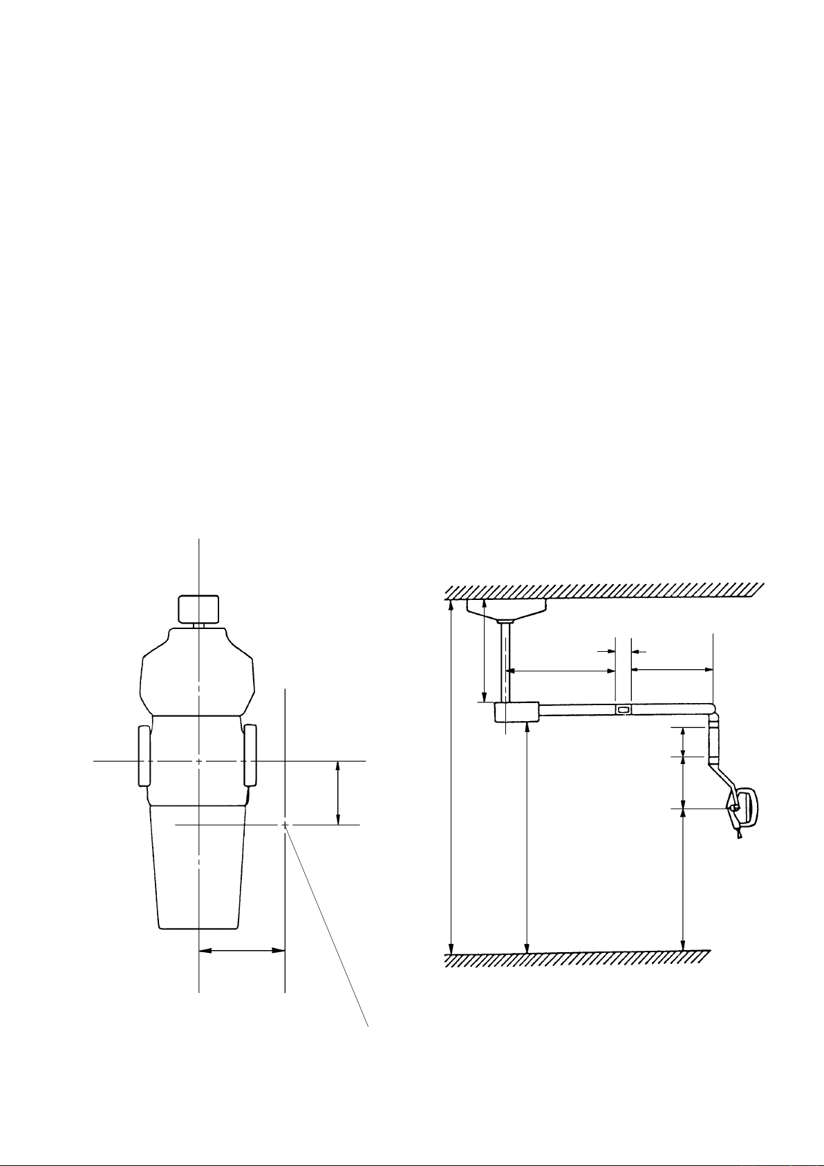
After determining desired location of light in reference to chair position (see illustration), some
alterations (framing, reinforcing), may be required and should be discussed with your local
contractor or builder. Major structural modications are not required, however the mounting
bolts used and area of ceiling mounted to should be able to withstand a 250lb. pull-out per
bolt. (This is needed to provide ample protection from side impact loads.)
ELECTRICAL REQUIREMENTS:
Standard 3-wire Romex or conduit w/junction box mounted per local code.
Power required: 0.53 amp at 115 VAC.
A full-size mounting template, dimensions, and suggested methods of installation are as fol-
lows:
This installation must be done by a licensed electrician only, in accordance with the National
Electrical
plicable.
Code(in the USA) or Canadian Electrical Code(in Canada), and local electrical codes as ap-
C
18"
12"
DIMENSIONS
min. 19-11/16"
96"
25-1/2"
74-13/16"
11/16"
22-3/16"
8-1/16"
7-3/16"
45-1/4" ~ 70-1/2"
C
LOCATION OF LIGHT MOUNT (CEILING)
IN REFERENCE TO CHAIR POSITION
Page 3
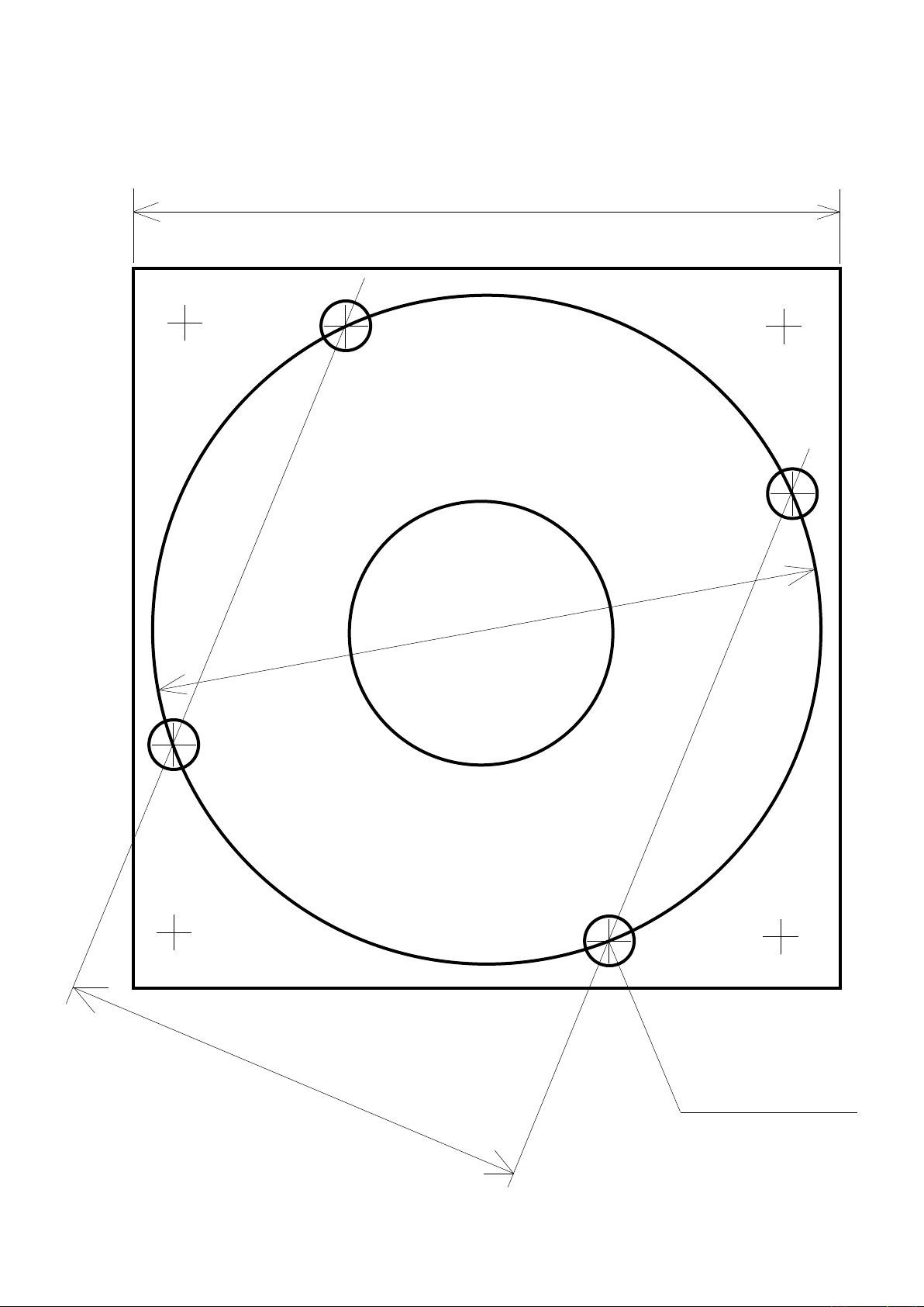
FULL-SIZE MOUNTING TEMPLATE
6-15/32 (REF)
6-1/16 (REF)
4-9/32 (REF)
7/16
MOUNTING HOLES
Page 4
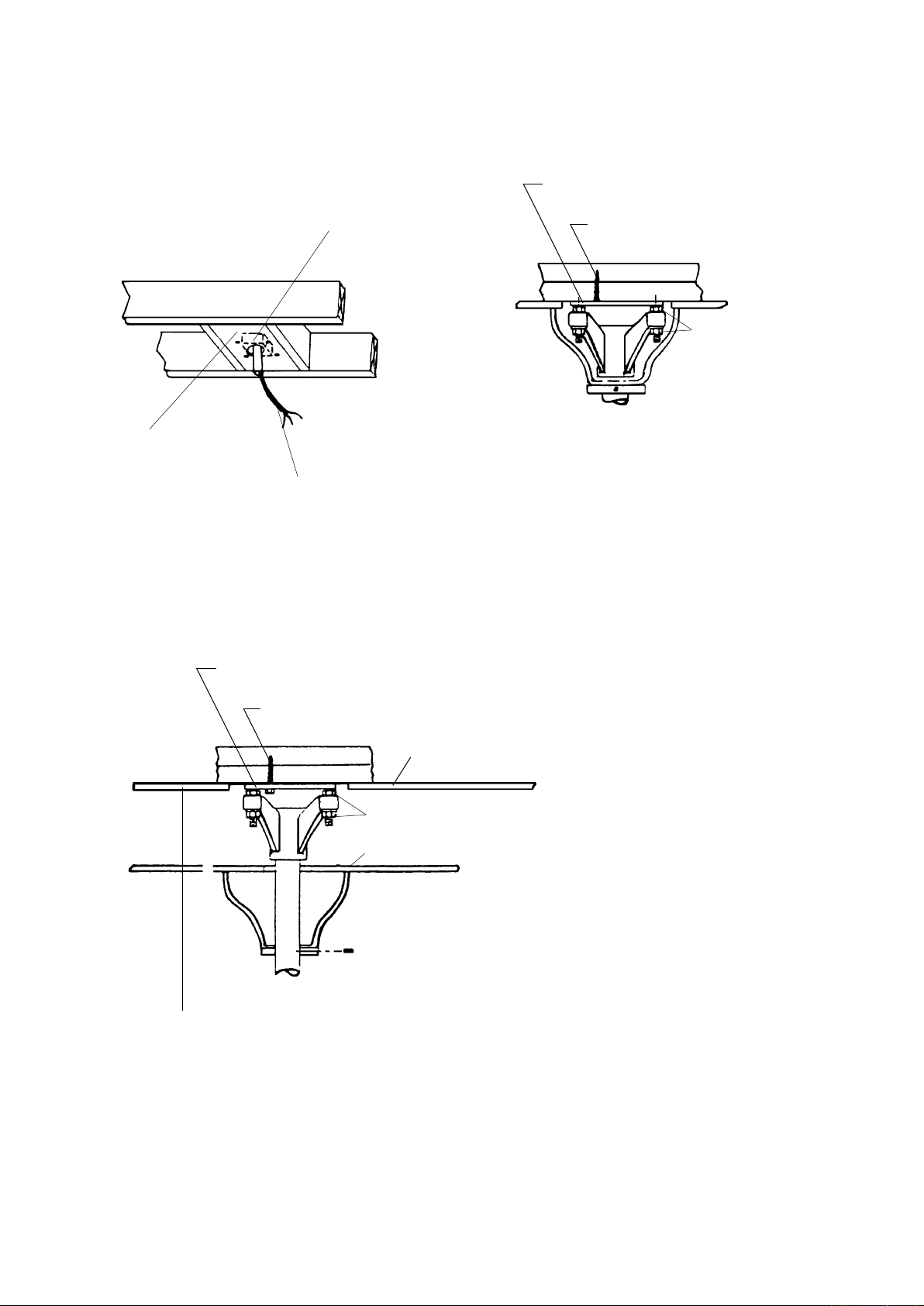
In conventional ceilings with joist construction, a double 2 x 12 bridge block securely boxed in
place is suitable for attachment of mounting plate with four 5/16" x 3" lag bolts.
MOUNTING PLATE
JUNCTION BOX PER LOCAL CODE
2 x 12
SECURELY
FASTENED
TO FRAMING
POWER CABLE
LAG BOLT
USE FOR LEVELING
For suspended ceilings, appropriate rigid structure must be attached to ceiling framework.
Required lamp height must be determined from permanent ceiling, not suspended ceiling.
MOUNTING PLATE
LAG BOLT
PERMANENT CEILING
USE FOR LEVELING
SUSPENDED CEILING
DETERMINE REQUIRED LAMP HEIGHT FROM PERAMANENT
CEILING, NOT SUSPENDED CEILING.
Page 5
Level Adjusting Nut
Washer
Nut
Wing Nut for Shipping
Purpose ONLY.
Remove before use.
NOTE: Before removing
countersink screws
15
remove set screws 23.
INSTALLATION INSTRUCTIONS
2
1
3
4 5
2
1
3
4 5
2
3
4 5
2
3
4 5
4 5
4 5
3
4 5
3
4 5
2
1
3
4 5
2
1
3
4 5
2
3
4 5
2
3
4 5
2
3
4 5
2
3
4 5
2
3
4 5
2
3
4 5
7
8
9
10
4 5
4 5
9
10
2
3
4 5
2
3
4 5
7
8
9
10
4 5
4 5
9
10
2
3
4 5
2
3
4 5
7
8
9
10
3
4 5
3
4 5
8
9
10
2
1
3
4 5
2
1
3
4 5
6
7
8
9
10
2
1
3
4 5
2
1
3
4 5
2
3
4 5
2
3
4 5
3
4 5
3
4 5
4 5
4 5
2
1
3
4 5
2
1
3
4 5
6
7
8
9
10
2
3
4 5
2
3
4 5
7
8
9
10
3
4 5
3
4 5
8
9
10
4 5
4 5
9
10
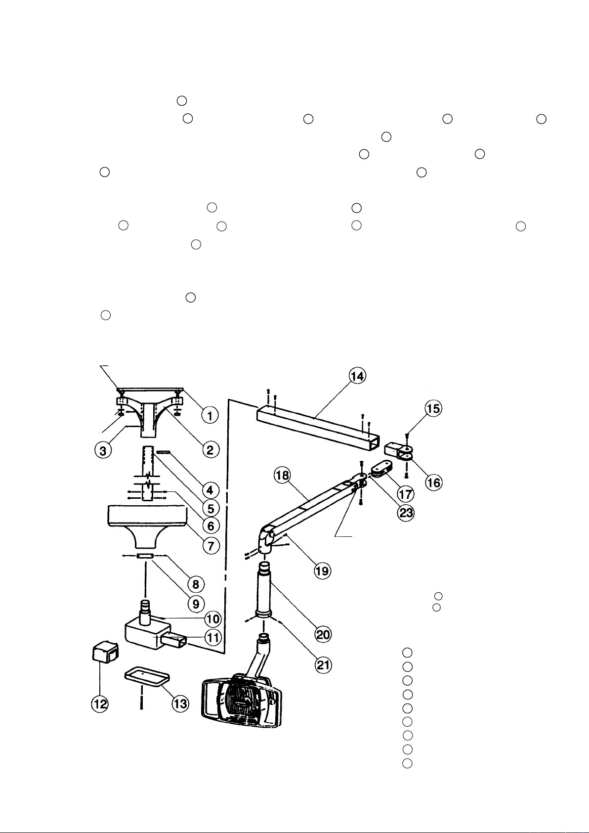
1). Lead out power supply cable from ceiling where light is to be mounted.
2). Attach mounting plate
3). Insert suspension tube
4). Run power cable through ceiling ange and suspension tube
5). Insert four level adjusting nuts between mounting plate
ange
with four washers and nuts. (Be sure suspension tube
to the ceiling
to the ceiling ange
and secure with roll pin
.
and ceiling ange
is perpendicular, if not,
and set screws
, then x the
.
adjust with level adjusting nuts.)
6). Slide the ceiling light cover
cover ring
up to the cover
tighten three set screws
on the suspension tube
(at surface of the ring
.
up to the mounting plate, then slide
must be ush against cover
) and
7). Connect three wires of power cable to wires from transformer of light. (Black - power, White -
neutral, Green - ground.)
8). Insert suspension tube
screws
.
connector of light assembly to suspension tube and tighten four set
Mounting Plate
Ceiling Flange
Set Screw
Roll Pin
Suspension Tube
Set Screw
Ceiling Light Cover
Set Screw
Cover Ring
Page 6
OPERATION & SERVICE INSTRUCTIONS
COUNTERCLOCKWISE
CLOCKWISE
ADJUSTING BAR
HEAD
COUNTERCLOCKWISE
CLOCKWISE
ADJUSTING BAR
SWING ARM
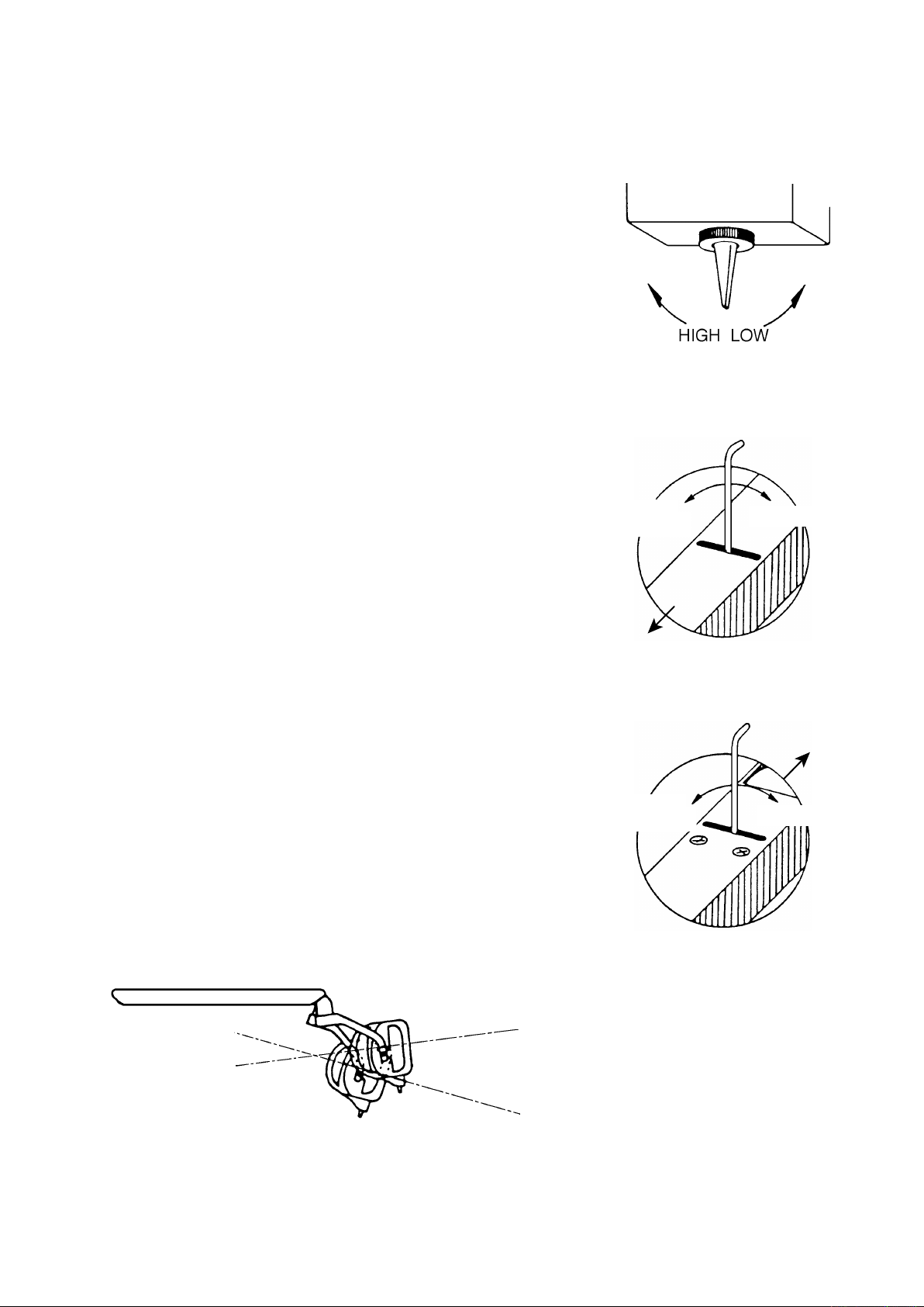
DUAL INTENSITY ON/OFF SWITCH
1. High Beam; push toggle to left
2. Low Beam; push toggle to right
Switch is conveniently located in light head, enabling intensity
to be changed from seated position.
Low Intensity - for longer lamp life and examining facial sur-
faces.
High intensity - for color matching and examining lingual sur-
faces.
BALANCE ARM ADJUSTMENT (Should drifting occur)
IMPORTANT; Use slot closest to head when making adjust-
ment for drifting of balance arm. Insert adjusting bar into slot
on top of balance arm, turn spring adjustment nut clockwise
for more tension; counterclockwise for less tension.
HEAD ANGLE ADJUSTMENT
IMPORTANT; Use slot closest to swing arm (H-shaped cast-
ing bracket) when adjusting angle of head. Insert adjusting
bar into slot on top of balance arm, turn head angle adjust-
ment nut clockwise for downward angle; counterclockwise
for upward angle.
Adjusting bar is supplied in envelope with Allen Wrenches.
Upward angle when turning
head angle sdjustment nut
counterclockwise.
Downward angle when turning
head angle adjustment nut
clockwise.
Page 7
OPERATION & SERVICE INSTRUCTIONS
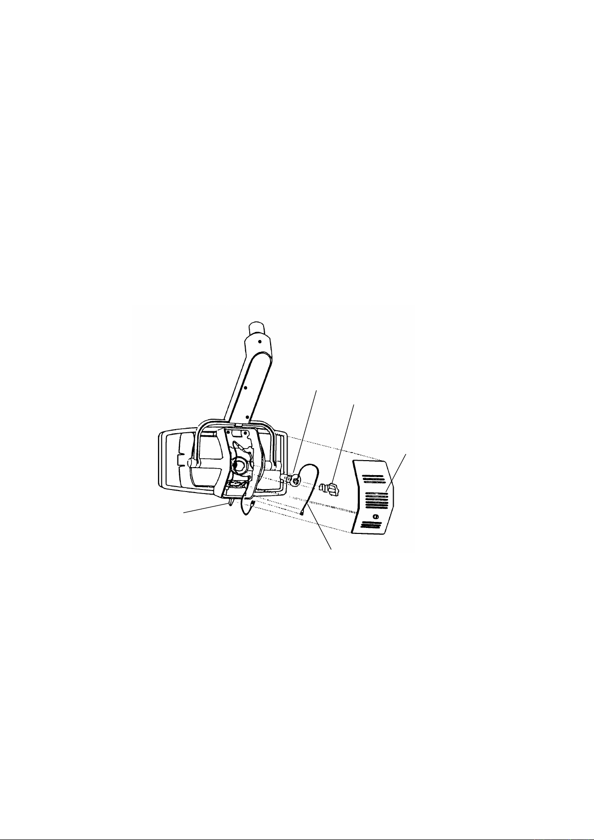
LEAD WIRE
DUAL INTENSITY
ON/OFF SWITCH
BULB RETAINER
BULB
BACK COVER
BULB CHANGING
1. To install replacement bulb (BELMONT H-3), turn unit off and remove back cover.
2. Push in and turn counterclockwise knob of bulb retainer to remove bulb retainer.
3. Remove bulb by grasping lead wire and pull bulb from housing. Disconnect lead wire
when bulb is completely removed.
4. Clean new replacement bulb surface with alcohol, attach lead wire and insert new bulb into
housing.
5. After new bulb is seated in housing, insert and lock bulb retainer into position.
IMPORTANT; Do not touch glass with bare hand. Light bulb surface must be clean. Oil or body
moisture will affect light intensity and bulb life. If glass surface is touched, clean
with alcohol.
CLEANING
Use soft cloth or cotton only. Soak with alcohol. Clean both sides of lens. Inside surface of re-
ector can be cleaned with a soft damp or dry cloth. Back side of the reector should be wiped
gently with a soft cloth. Extreme care should be taken not to scratch surface or mar appearance
of painted surfaces. Exterior cleaning is all that should be necessary until after many months of
use.
LUBRICATION
A drop of oil once a year at pivot points will provide ample lubrication.
Page 8
SPECIFICATIONS:
Input voltage.......................... 115V, 60Hz, 0.53A
Output voltage....................... 12V high, 10.5V low
Power output......................... 55w high, 50w low
Type bulb.............................. Tungsten halogen, Type JA 12V - 55w
Focal Distance...................... 28" (725mm)
Light output........................... 2600 fc - High, 1400 fc - low
color temperature.................. 3800˚Kelvin
Light pattern.......................... 3" x 7" at 28" focal distance
(75 x 180 at 725 mm)
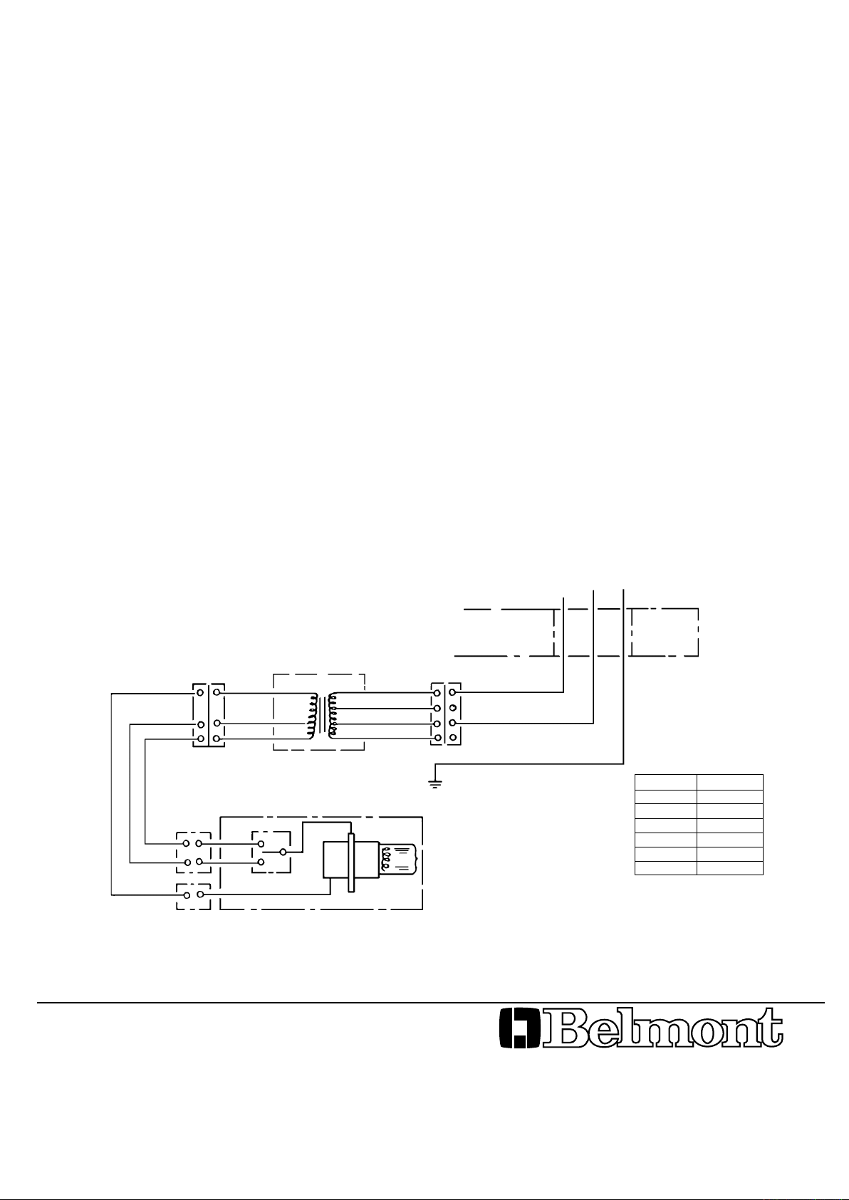
WIRING DIAGRAM
3P CONNECTOR
B
R
O
O
R
B
B
R
O
TRANSFORMER
SWITCH
0V
10.5V
12V
0V
100V
115V
120V
POWER SUPPLY
115 V 60 Hz
4P CONNECTOR
W
BK
G
GROUND
HALOGEN LAMP
JA 12V 55W
LIGHT HEAD
W
BK
G
SYMBOL COLOR
B BLUE
BK BLACK
G GREEN
O ORANGE
R RED
W WHITE
BELMONT EQUIPMENT CORPORATION
101 Belmont Drive, Somerset, N.J. 08873, U.S.A.
(732)469-5000, Toll Free (800) 223-1192
2076 S. Sheridan Way, Mississauga,Ont., Canada
(905) 822-2755
Printed in Japan Rev.3 9803
 Loading...