


MODEL 096
DENTAL X-RAY
·Wall Mount Type..................... |
WK |
·Ceiling Mount Type................ |
CK |
·Floor Mount Type................... |
FK1 |
·Mobil Type.............................. |
FM |
·Room Mount Type................... |
RK II |
INSTALLATION
INSTRUCTIONS
IMPORTANT :
This manual provides information and instructions for the installation and calibration procedures for the BELMONT model 096 dental x-ray.
The instructions contained in this book should be thoroughly read and understood before at- tempting to install the x-ray unit. After the installation is completed, file this manual and refer back to it when performing periodic maintenance.
REV.5
INDEX |
|
|
PAGE |
SECTION ONE : TECHNICAL DATA |
|
[1] ELECTRICAL AND RADIATION DATA......................................................... |
3 |
[2] PHYSICAL DIMENSIONS................................................................................ |
4 |
[3] TUBE HEAD THERMAL CHARACTERISTICS............................................. |
6 |
SECTION TWO : PRE-INSTALLATION INSTRUCTIONS |
|
[1] SUPPORT REQUIREMENTS............................................................................ |
7 |
[2] ELECTRICAL REQUIREMENTS..................................................................... |
7 |
[3] LOCATION OF COMPONENTS....................................................................... |
8 |
SECTION THREE : INSTALLATION INSTRUCTIONS |
|
[1] INSTALLATION REQUIREMENTS................................................................. |
8 |
[2] UNPACKING...................................................................................................... |
9 |
[3] INSTALLATION OF WK / CK / FK / RKII / FM............................................ |
10 |
[4] HEAD ASSEMBLY INSTALLATION............................................................. |
16 |
[5] CONTROL BOX INSTALLATION................................................................. |
17 |
SECTION FOUR : POST INSTALLATION INSPECTION |
|
[1] ARM ASSEMBLY............................................................................................. |
19 |
[2] BALANCE ARM ASSEMBLY......................................................................... |
19 |
[3] HEAD POSITIONING...................................................................................... |
20 |
SECTION FIVE : CONTROL IDENTIFICATION AND OPERATION |
|
[1] CONTROL IDENTIFICATION........................................................................ |
20 |
[2] FUNCTION OF CONTROLS........................................................................... |
21 |
[3] OPERATING PROCEDURES.......................................................................... |
23 |
[4] ERROR CODES................................................................................................ |
24 |
SECTION SIX : POST INSTALLATION CONFIRMATION |
|
[1] CONFIRMATION OF POWER SUPPLY VOLTAGE..................................... |
25 |
[2] CONFIRMATION OF TUBE CURRENT........................................................ |
25 |
[3] CONFIRMATION OF EXPOSURE WARNING LAMP & BUZZER............. |
25 |
[4] CONFIRMATION OF LINE VOLTAGE REGULATION............................... |
25 |
SECTION SEVEN : INITIAL SETTING |
|
[1] FILM SPEED.................................................................................................... |
26 |
[2] PRIORITY OF SELECTIONS.......................................................................... |
28 |
[3] ELECTRONIC CHIME ON/OFF..................................................................... |
28 |
APPENDIX ONE : CIRCUIT DIAGRAM ............................................................ |
29 |
APPENDIX TWO : PARTS IDENTIFICATION |
|
[1] ARM AND HEAD ASSEMBLY....................................................................... |
30 |
[2] CONTROL BOX ASSEMBLY......................................................................... |
30 |
– –

SECTION ONE : TECHNICAL DATA
[1] ELECTRICAL AND RADIATION DATA
1. |
Nominal focal spot value............................................. |
0.8 mm (IEC) |
2. |
Rated peak tube potential............................................ |
70 kVp |
3. |
Rated tube current........................................................ |
10 mA |
4. |
Maximum rated peak tube potential............................ |
70 kVp |
5. |
|
|
Rated Line Voltage |
[Vac] |
110 |
120 |
220 |
230 |
240 |
Minimum LinVoltage |
[Vac] |
99 |
108 |
198 |
207 |
216 |
Maximum Line Voltage |
[Vac] |
121 |
132 |
242 |
253 |
264 |
Rated Line Power |
[kVA] |
1.3 |
1.3 |
1.3 |
1.3 |
1.3 |
Rated Line Current |
[Aac] |
11.4 |
10.8 |
5.7 |
5.6 |
5.5 |
Maximum Line Current |
[Aac] |
12.6 |
11.9 |
6.3 |
6.2 |
6.1 |
(Internal Resistance |
[ Ω ] |
(0.19~0.46) |
(0.22~0.53) |
(1.12 max) |
(1.20 max) |
(1.27 max) |
Range of Line Voltage Regulation |
[%] |
2 ~ 5 |
2 ~ 5 |
0 ~ 3 |
0 ~ 3 |
0 ~ 3 |
6. |
Power line frequency................................................... |
|
|
50/60 Hz |
|
|
|
7. |
Exposure time.............................................................. |
|
|
0.02 ~ 3 sec. |
|
|
|
8. |
Timer accuracy |
|
|
(ON and OFF are zero crossed.) |
|
) |
|
|
|
±1 pulse (1/50sec. for 50 ,1/60sec. for 60 |
Hz |
||||
9. |
Inherent filtration |
|
|
Hz |
|
||
|
|
1.3 mmAl Equivalent |
|
|
|||
10. Added filtration............................................................ |
|
|
0.8 mmAl |
|
|
||
11. Minimum filtration permanently in useful beam......... |
|
|
2.1 mmAl Equivalent at 70 kVp |
|
|
||
12. |
Nominal roentgen output |
|
|
8.2mGy/sec. + 30 %, - 40 % |
|
|
|
a. Distal end of regular cone............................................ |
|
|
|
|
|||
b. Distal end of long cone................................................ |
|
|
3.7mGy/sec. + 30 %, - 40 % |
|
|
||
13. |
Source to skin distance |
|
|
204 mm |
|
|
|
a. Regular cone................................................................ |
|
|
|
|
|||
b. Long cone.................................................................... |
|
|
305 mm (OPTION) |
|
|
||
14. |
Leakage technique factor............................................. |
|
|
70 kVp / 0.16 mA |
|
|
|
|
|
|
|
|
0.16 mA is maximum rated continuous current |
||
15. |
Duty cycle |
|
|
for 10 mA with a duty cycle 1: 60 |
|
|
|
|
|
1: 60 (0.5 sec. exposure with 30 sec. interval) |
|||||
16. |
Source to the base of cone distance............................. |
|
|
81 mm |
|
|
|
17. |
Reference current time product................................... |
|
|
30 mAs (70kVp, 10mA, 3sec.) |
|
|
|
18. |
Maximum earth leakage current.................................. |
|
|
0.5 mA |
|
|
|
19. |
Field size...................................................................... |
|
|
Round 58 mm |
|
|
|
20. |
Tolerance of the focal spot marking............................ |
|
|
±1 mm |
|
|
|
21. |
Tolerance of target angle............................................. |
|
|
1˚ |
|
|
|
|
|
|
|
|
Focal spot marking |
|
|
|
|
|
|
|
|
|
|
|
Reference axis |
|
|
|
|
|
|
|
|
|
|
|
|
|
|
22. |
Measurement base of technique factors |
|
|
Peak tube potential of conducting half cycle |
|
||
a. Peak tube potential....................................................... |
|
|
|
||||
b. Tube current................................................................. |
|
|
Average of tube current during one cycle of |
|
|||
c. Exposure time |
|
|
line frequency |
|
|
||
|
|
Impulese of power line frequency |
|
|
|||
|
|
-3A |
- |
|
|
|
|
|
|
– |
– |
From 2006 April |
|||
|
|
|
|
|
|||

[2] PHYSICAL DIMENSIONS
[unit : mm]
096-WK Wall Monut Type
1060
0˚
600˚
9 |
00 |
Max. 1190 |
90 |
|
OPTION: |
Stroke : 1100 |
|
|
00 or 00 |
|
|
|
Horizontal Arm |
|
|
|
is available. |
|
|
Max. 199
Min. 9
|
|
|
19 |
|
|
|
300˚ |
9 |
|
1 9 |
0 |
Min. Max. |
||
|
||||
|
|
– – |
From 2004 July |

[unit : mm]
096-CK Ceiling Type
|
|
106 |
300˚ |
220˚ |
|
|
600˚ |
|
|
|
|
00 |
Max. 1190 |
90 |
|
Stroke 1100 |
|
|
(183) |
|
|
|
|
69 |
|
|
|
(00) |
|
|
|
|
196 |
|
|
|
|
19 |
10 |
1 : 1100 |
0 |
300˚ |
|
|
Max. Stroke |
|
|
|
|
|
|
096-FM Mobile Type
6 0 |
|
|
|
90 |
|
|
|
|
|
|
|
6 |
|
|
106 |
|
|
600° |
|
Max. 1190 |
90 |
|
|
Stroke : 1100 |
|
|
|
Max. 69 |
|
|
|
|
|
00° |
Max. 0 |
|
|
|
|
1 |
|
1100: |
|
|
916 |
|
|
|
|
Max. |
|
|
|
Stroke |
|
096-FK1 Floor Type
220˚ |
106 |
|
|
220˚ |
600˚ |
|
00 |
Max. 1190 |
|
90 |
|
Stroke 1100 |
|
|
Max. 69 |
|
|
|
9 |
|
|
1 |
|
|
|
Max. |
|
Max. 1 00 |
0 |
300˚ |
|
|
||
1 |
|
|
1 : 1100 |
|
|
|
Max. Stroke |
096-RKII Room Type
|
00 |
|
|
|
|
180˚ |
|
|
|
|
|
|
|
|
|
|
00 |
|
|
260˚ |
|
|
106 |
|
|
|
|
|
|
|
|
|
|
|
600˚ |
|
00 |
0 |
|
|
|
106 |
0 |
|
190 |
90 |
Stroke 00 |
Max. 01 |
|
|
|
|
Max. 1 |
|
|
00 |
|
|
300˚ |
|
|
|
|
|
|
|
|
Stroke |
|
|
|
|
|
|
06 |
|
|
|
|
0 |
Max. |
|
|
– – |
From 2004 July |

[3]TUBE HEAD THERMAL CHARACTERISTICS A. Interval between each exposure
The temperature inside of the tube head rises, when an exposure is made. The value of the heat generated is measured in Heat Unit (HU), which is the product of tube potential, tube current and exposure time. Excessive heat will be accumulated inside of the tube head, if the x-ray is used without a proper cool down interval between each exposure. The excessive heat may damage the x-ray tube, high voltage generator or both.
B. Duty cycle
To avoid the accumulation of excess heat in an effort to prolong the tube head life, a cool down interval of 60 seconds or more must be allowed between each 1 second exposure. or a 30 second
cool down must be allowed between each 0.5 second exposure.
C.Tube head cooling curve
1.Tube Housing cooling curve
Tube Housing Cooling Curve
|
0 |
|
(KH.U.) |
00 |
|
1 0 |
||
Storange |
||
100 |
||
Heat |
||
|
||
|
0 |
0 |
0 |
0 |
60 |
0 |
100 |
1 0 1 0 |
Time in Minutes
2. Anode thermal characteristics
|
0000 |
|
ANODE THERMAL CHARACTERISTICS |
|
|
|
|
|
|||||||||||||
|
|
|
|
|
|
|
|
|
|
|
|
|
|
|
|
|
|
|
|
|
|
|
1 000 |
|
S |
|
|
|
|
/S |
|
|
|
|
|
|
|
|
|
|
|
|
|
|
|
|
|
|
|
U |
|
|
|
|
|
|
|
|
|
|
|
|
|
||
|
|
|
/ |
|
|
|
H |
|
|
|
|
|
|
|
|
|
|
|
|
|
|
|
|
|
U |
|
|
|
|
|
|
|
|
|
|
|
|
|
|
|
|
|
|
|
|
|
H |
|
|
|
|
|
|
|
/S |
|
|
|
|
|
|
|
|
|
|
|
|
|
|
|
|
|
|
|
|
|
|
|
|
|
|
|
|
|
|||
|
|
|
|
|
|
|
|
|
|
|
U |
|
|
|
|
|
|
|
|
|
|
|
|
|
|
|
|
|
|
|
H |
|
|
|
|
|
|
|
|
|
|
||
|
|
|
1 |
|
|
|
|
|
|
|
|
|
|
|
|
|
|
|
|
|
|
|
|
|
|
|
|
|
|
|
|
|
|
|
|
|
|
|
|
|
|
|
|
(H.U.) |
1 000 |
|
|
|
|
|
|
|
1 |
|
|
|
|
|
|
|
|
|
|
|
|
|
|
|
|
|
|
|
|
|
|
|
|
|
|
|
|
|
|
|
|||
|
|
|
|
|
|
|
|
|
|
|
|
|
|
|
|
|
|
|
|
|
|
StorangeHeat |
10000 |
|
|
|
|
|
|
|
|
|
|
|
|
TUBE |
|
MODEL |
|
D-0 |
|
|
|
|
|
|
|
|
|
|
|
|
|
|
|
|
|
|
|
|
|||||
|
|
|
|
|
|
|
|
|
|
|
|
|
|
|
|
|
|
|
|
|
|
|
|
|
|
|
|
|
|
|
|
|
|
|
|
|
|
|
|
|
|
|
|
|
6000 |
|
|
|
|
|
|
|
|
|
|
|
|
|
|
|
|
|
|
|
|
|
|
|
|
|
|
|
|
|
|
|
|
|
|
|
|
|
|
|
|
|
|
|
000 |
|
|
|
|
|
|
|
|
|
|
|
|
|
|
|
|
|
|
|
|
|
|
|
|
|
|
|
|
|
|
|
|
|
|
|
|
|
|
|
|
|
|
|
|
|
|
|
|
|
|
|
|
|
|
|
|
|
|
|
|
|
|
|
|
|
0 |
|
1 |
|
|
|
|
|
|
|
|
6 |
|||||||||
|
|
|
|
|
|
|
|
|
|
Time in Minutes |
|
|
|
|
|
||||||
3. Maximum rating chart
|
0 |
|
(mA) |
0 |
|
Tube Current |
||
10 |
FOCAL SPOT 0.8mm
0 kV
60 kV
0 kV0 kV
90 kV
0.1 |
0. 0. |
0. 0. 1.0 |
.0 .0 |
.0 |
|
|
Load Time (sec.) |
|
|
––

SECTION TWO : PRE-INSTALLATION INSTRUCTIONS
[1] SUPPORT REQUIREMENTS
Control box:
When mounting the MODEL 096 WK control box, the wall and mounting hardware must be sufficient to withstand a 12 kg shear load.
Arm and head:
(1) Wall mount type (WK)
The wall and mounting hardware for arm mounting bracket must be sufficient to withstand a 45 kg shear load and a 200 kg withdrawal force at each of the three mounting bolts. If wall dose not have enough strength, use the wall mounting plate(option). This plate is designed for mounting on two 2
X 4 wood studs with 16 inch center. With this plate, wall and mounting hardware must be sufficient to withstand a 45 kg shear load and a 200 kg withdrawal force at each of the four mounting bolts.
(2) Ceiling mount type (CK)
The ceiling and mounting hardware for mounting plate must be sufficient to withstand a 150 kg (330 pounds) withdrawal force.
(3) Floor mount type (FK1)
The floor and mounting hardware for floor mounting plate must be sufficient to withstand a 100 kg
(220 pounds) withdrawal force.
 CAUTION :
If the MODEL096 is to be mounted in a manner other than what is specified in this manual or if the hardware to be used is other than what is supplied, the support capability of the wall and the strength of the hardware must be checked and verified to be adequate.
[2] ELECTRICAL REQUIREMENTS
Power supply:
The MODEL 096 x-ray system will operate on a power supply of rated line voltage ± 10% with a three wire (hot, neutral, earth) circuit, separately connected to the central distribution panel with an over cur- rent protection device. Use sufficient wire size as the line voltage regulation should be within the range of 2~5 % for 120V, 0~3% for 220~240V at rated current.
Concealed wiring for WK type:
Concealed wiring is accomplished by bringing conduit and wires into (2) flush mounted junction boxes located (1) behind the control box and (1) behind the arm mounting bracket. Recommended heights for the
flush junction boxes are : 131cm for behind control box and 113cm for behind arm mounting bracket. Wiring done in this manner should extend 30cm beyond the wall surface to allow sufficient wire for connections.
|
|
Junction |
|
|
Boxes |
(1) |
|
( ) |
FROM |
|
|
POWER |
|
|
SOURCE |
|
|
|
|
WALL |
L N |
6 |
6 |
NOTE:
Terminal Block |
Pigtail for Arm |
for Control Box |
Mounting Bracket |
All connections, workmanship and materials used must comply with the local codes.
– –

[3] LOCATION OF COMPONENTS
A. Arm and head assemblies for WK type:
Using the information provided in FIGURE 1, determine the correct location for the installation of the arm and head assemblies for WK type. (unit : mm)
NOTE: Local requirements supersede guide lines indicated below.
|
( ) : WITH LONG CONE |
|
|
|
|
|
|
100 |
|
|
|
1 9 |
|
|
0˚ |
|
1 9 |
|
|
|
100 |
||
|
|
|
|
|
|
0 |
0 |
9 |
|
100 |
|
|
11 0 |
|
|||
|
|
|
|
|
|
B. Control box :
When determining the location for the control box the following radiation requirements concerning operator positioning must be considered. The operator must;
1.have full view of the patient.
2.have full view of kVp, mA, timer selections and exposure warning light.
3.be a minimum of 1.8 meter away from the patient.
4.be out of line of the useful beam of radiation or be positioned behind a protective device with X-ray protection equivalent of 1 mm of lead.
SECTION THREE : INSTALLATION INSTRUCTIONS
Within the installation and confirmation procedures are inspection/test steps which the installer must perform to insure that the installation meets the manufacturer’s specifications.
[1] INSTALLATION REQUIREMENTS
Tools:
Standard tool kit including wire crimping pliers (AMP, “Super Champ” or equivalent). 1.5 mm, 2 mm, 3 mm and 5 mm allen keys.
Instruments:
Digital multimeter with an accuracy of 1%, capable of measuring 300 V AC, and capable of indicating true RMS value within 1 second.
Standard calculator.
POWER SUPPLY:
Prior to starting the installation inspect the power supply and confirm that the power supply is with rated line voltage ±10%, and that the supply is a 3 wire EARTHED circuit, separately connected to the central distribution panel with an overcurrent protection device.
– – |
From 2004 July |
[2] UNPACKING
Unpack the entire contents of the shipping carton. Included within the shipping carton are:
Identification |
Quantity |
Head............................................................................................................. |
1/WK,FK,FM,CK,RKII |
Regular Cone................................................................................................ |
1/WK,FK,FM,CK,RKII |
Long Cone...................................................................................... |
(1)/WK,FK,FM,CK (OPTION) |
Control Box.................................................................................................. |
1/WK,FK,FM,CK,RKII |
Head key...................................................................................................... |
1/WK,FK,FM,CK,RKII |
Collar............................................................................................................ |
1/WK,FK,FM,CK,RKII |
Balance Arm................................................................................................. |
1/WK,FK,FM,CK |
Balance Arm Wrench................................................................................... |
1/WK,FK,FM,CK |
Horizontal Arm W/ 2/Screw Cover.............................................................. |
1/WK,FK |
Arm Mounting Bracket W/3 Coach Bolt ø9, 3/Bolt cap.............................. |
1/WK |
Wall Plate W/4 Coach Bolts, 3 bolts, Washers,7/bolt cap and template...... (1)/WK (OPTION) |
|
Brake Screw (M6 x 6mm)............................................................................ |
2/WK,FK 1/FM,RKII |
Brake Plug (Brass Plug)............................................................................... |
2/WK,FK 1/FM,RKII |
Retaining Bolt (M6 x 35mm)....................................................................... |
2/WK |
Stopper Screw (M6 x 15mm)....................................................................... |
1/WK,RKII 2/FK,FM |
Control Box Mounting Screw (ø5.8 x 32mm)............................................. |
4/WK,FK,CK,RKII |
Pole............................................................................................................... |
1/FK,FM,CK |
Mounting Plate (ø350mm) W/ 6 coach boltø9............................................. |
1/FK,CK |
Floor/Ceiling Cover..................................................................................... |
1/FK,CK |
Control Box Mounting Plate........................................................................ |
1/FK,FM |
Back Supporter............................................................................................. |
2/FK,FM |
FK/CK Mounting Bolt (M8 x 20mm) W/ 3 spring washer.......................... |
6/FK,CK |
Brake Spring (ø5)......................................................................................... |
1/FK,FM,RKII |
Leg............................................................................................................... |
2/FM |
Free Caster................................................................................................... |
2/FM |
Brake Caster................................................................................................. |
2/FM |
Swing Arm................................................................................................... |
1/CK |
Light Arm..................................................................................................... |
1/CK |
Base.............................................................................................................. |
1/RKII |
Column......................................................................................................... |
1/RKII |
Sliding Post.................................................................................................. |
1/RKII |
Swing Arm................................................................................................... |
1/RKII |
Gas Pump..................................................................................................... |
1/RKII |
Seat............................................................................................................... |
1/RKII |
Lag Bolt (ø8 x 45mm).................................................................................. |
5/RKII |
Manual......................................................................................................... |
1/WK,FK,FM,CK,RKII |
Inspect contents of shipping carton for damage or missing components.
––
[3a] INSTALLATION OF WK TYPE
When mounting MODEL 096 arm bracket, the wall and the strength of the hardware used must be checked and verified as being adequate to withstand a 45 kg shear load and 200 kg withdrawal force at each of the three mounting bolts. When using concealed wiring, a flush mounted junction box with the necessary conduit and wiring must be pre-installed at 113 cm from the floor.
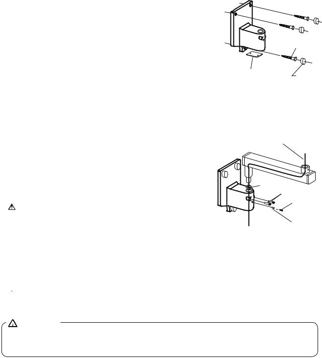
1. ARM MOUNTING BRACKET (FIGURE 2):
1-1. Remove bottom cover from bottom of the arm mounting bracket. Snake electrical interconnecting wires through bracket and out access hole.
1-2. Using ø 9 X 75 mm bolts in top and lower mounting holes, mount arm mounting bracket on wall. DO NOT FULLY TIGHTEN.
1-3. Placing a level across top edge of arm mounting bracket, level bracket then tighten bolts securely.
1-4. Put the bolt cap to each head of bolt.
2. HORIZONTAL ARM (FIGURE 3):
|
ø9 x Bolt |
|
Bottom Cover |
Bolt Cap |
|
FIGURE 2 |
||
|
2-1. Cut pull string on horizontal arm. DO NOT REMOVE STRING.
ALLOW ONE END TO EXTEND BEYOND MALE BARB AND THE OTHER END TO EXTEND BEYOND THE FEMALE MOUNT.
2-2. Place a thrust washer over the hole of arm mounting bracket, and insert male barb into arm mounting bracket,
allowing pull string to extend through access opening on bottom of the arm mounting bracket.
2-3. Insert two retaining bolts securely into upper threaded holes of arm mounting bracket and tighten securely.
IMPORTANT: The retaining bolts must securely engage the annular groove of horizontal arm. The removal of the
retaining bolts will allow the horizontal arm to rise vertically, and out of, the arm mounting bracket.
2-4. Insert brake plug then brake screw (M6x6 mm) into the lower threaded hole of the arm mounting bracket.
DO NOT FULLY TIGHTEN.
2-5. Place a level on the horizontal arm and confirm that the arm is level in its left and right swing positions.
 NOTE: Final leveling of horizontal arm is described on Page 19.
3. BALANCE ARM ASSEMBLY (FIGURE 4):
 WARNING:
DO NOT RELEASE ARM HOLDING BAND UNTIL THE X-RAY HEAD HAS BEEN INSTALLED. BALANCE ARM ASSEMBLY IS SPRING LOADED AND CAN CAUSE EQUIPMENT DAMAGE AND INJURY IF NOT HANDLED IN THE PROPER MANNER.
3-1. DO NOT REMOVE ARM HOLDING BAND.
3-2. Secure pull string to cable and pulling the opposite end, snake cable through horizontal arm and arm mounting bracket.
3-3. Insert brake plug then brake screw (M 6 X 6 mm) into the horizontal arm collar.
DO NOT FULLY TIGHTEN.
– 10 –
 Loading...