

Page 1

B02-T151
Operation Manual
Panoramic Radiograph&Cephaloradiograph
BelmaX CM
Notice to the operator and maintenance supervisor
*Read this instruction manual before operation. After reading this manual,
safely keep this near the X-ray machine for the easy access.
The classification is shown as follows
According to the type of protection against electric shock. :
According to the degree of protection against electric shock. :
TAKARA BELMONT U.S.A., INC.
Class Ⅰ
Type B applied part
Page 2
B02-T151 15
15.Operation Procedures for Cephalo Lateral
(LA)
1. Learn the Panoramic radiographic operation procedures well. You can utilize Panoramic
operating procedures for other modes.
2. If procedures are the same as the ones of Panorama, explanations of operation
procedures in other modes are omitted. If you have an y questions, Refer to operation
procedures for Panorama.
1.Preparation for exposure
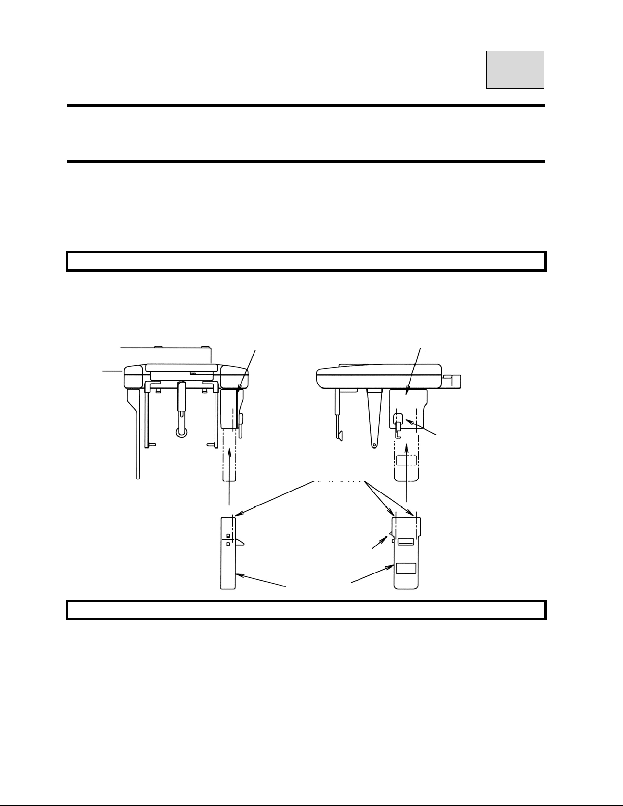
Set up CCD sensor
Hold CCD sensor by both hands and set up CCD sensor.
Secure CCD sensor by connecting sensor’s hook and fall prevention’s hook.
Sensor holder
Sensor holder
2.Turning power ON
Fall prevention hook
Hole of guide pin
CCD sensor hook
CCD sensor
Page 3
B02-T151 15
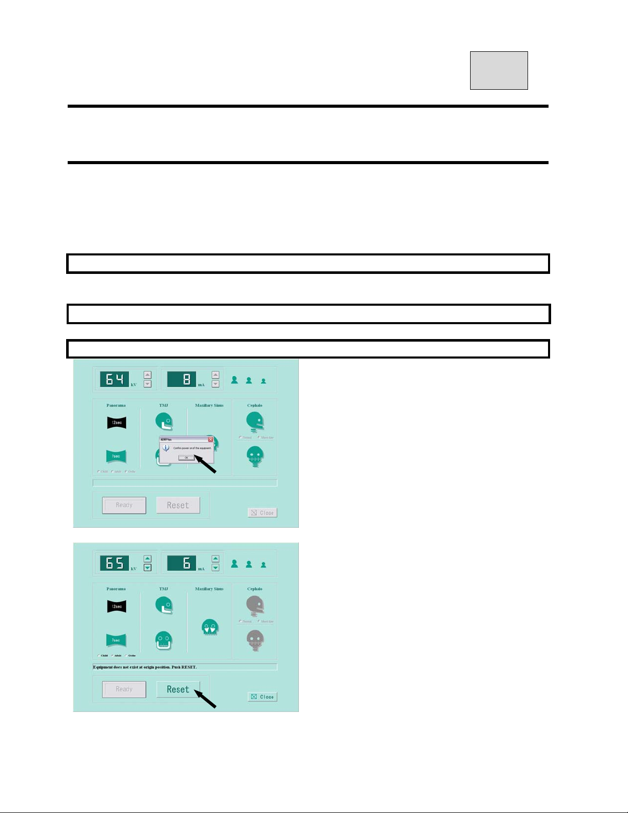
3.Exposure Setting Screen
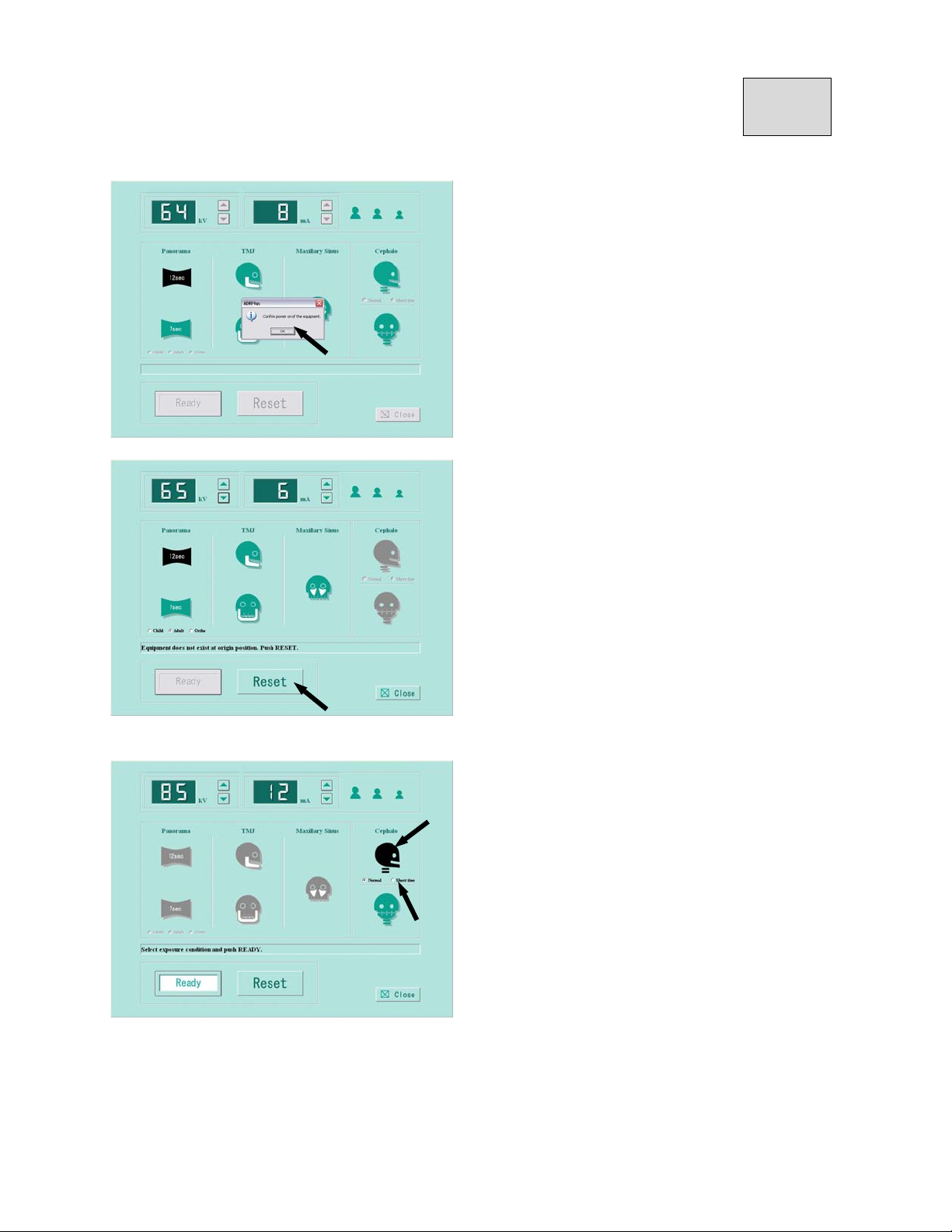
Click either “Import” or “Scan” from diagnosticsoftware / i
maging software.
If the power of the equipment is ON,
click OK.
f you receive the message「Equipment is not at
the original position. Push the RESET button.」
Then click the「RESET button」.
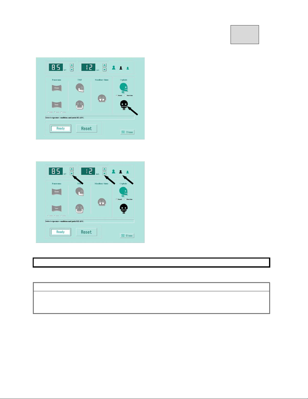
Set the exposure mode
Click Cephalo Lateral icon.
After select, icon will be changed to black.
Select either normal (4 sec) or short time (2.9 sec).
Setting kV(tube voltage)・mA(tube current)
Refer to article 17 for Cephalo Lateral exposure condition and setting exposure condition.
Page 4
B02-T151 15
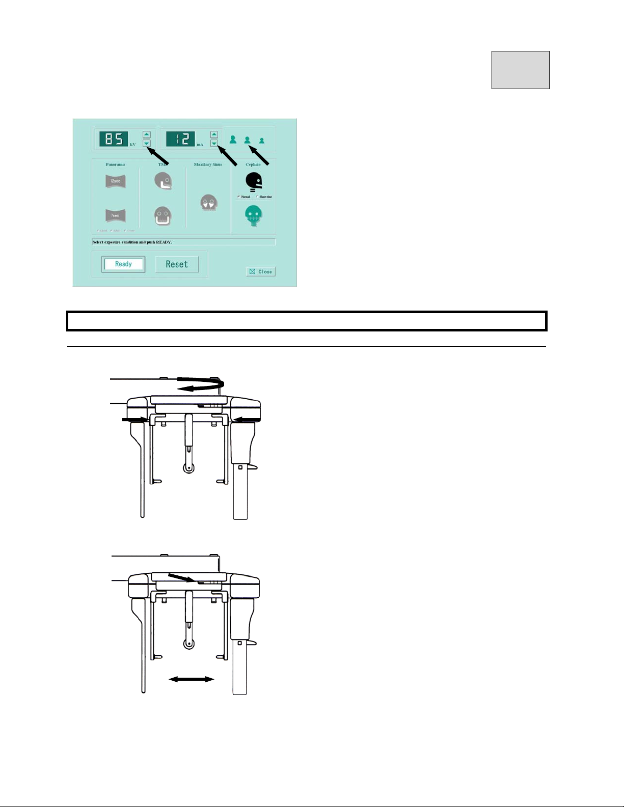
Setting kV(tube voltage)・mA(tube current)
Set kV
Click kV ▲(UP)・or ▼(DOWN)to set kV.
Set mA
Click mA ▲(UP)・or ▼(DOWN)to set mA.
4.Patient Positioning
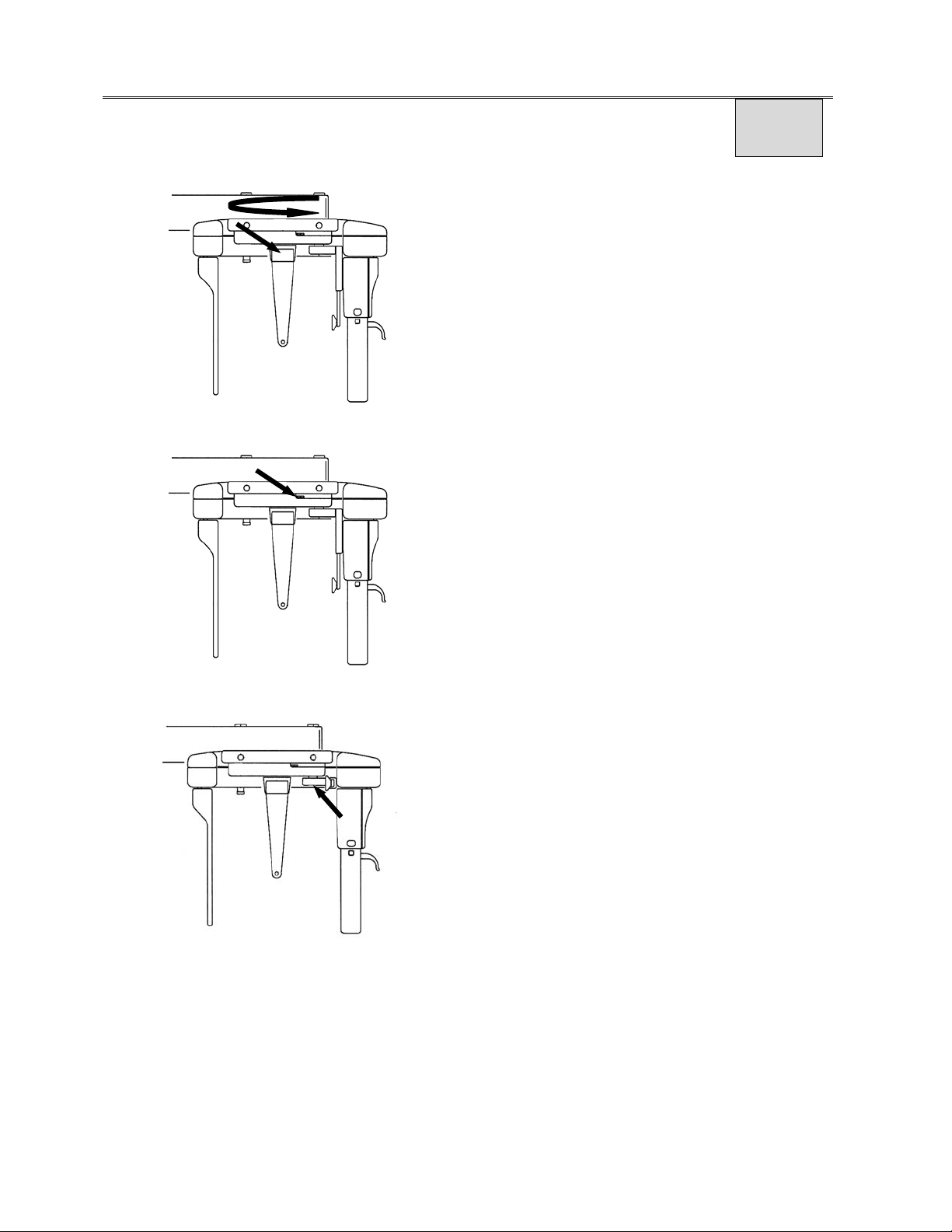
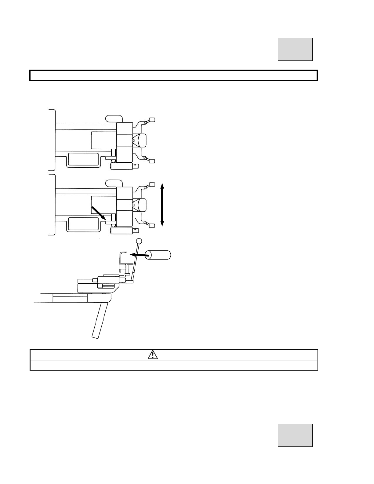
4.1.Aling Ear Rod with exposure direction
①Rotate Ear Rod by holding the fixing
portion of Ear Rod, align Ear Rod to
exposure direction of Cephalo Lateral.
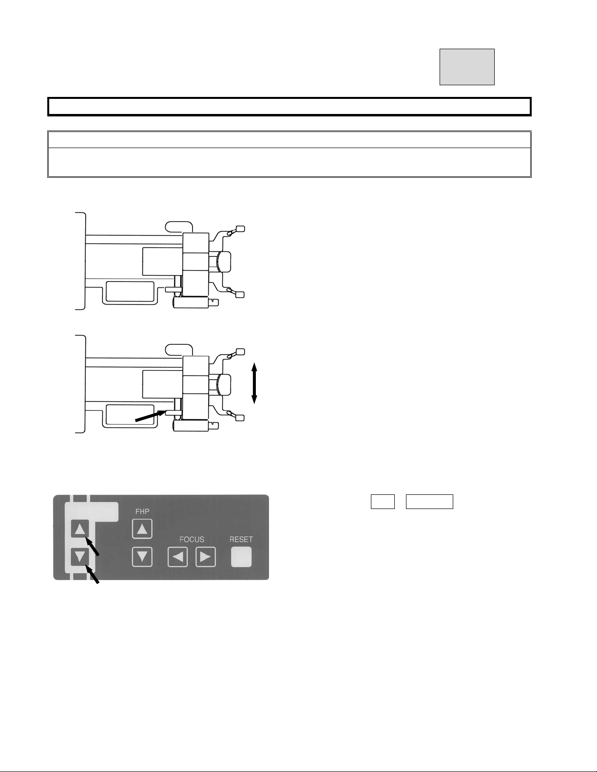
②Move Open-Close Lever for Ear Rod of
Cephalo stat to open Ear Rod maximally.
Page 5
B02-T151 15
Put X-ray protector apron on a patient and an assistant.
Guide a patient near to the equipment.
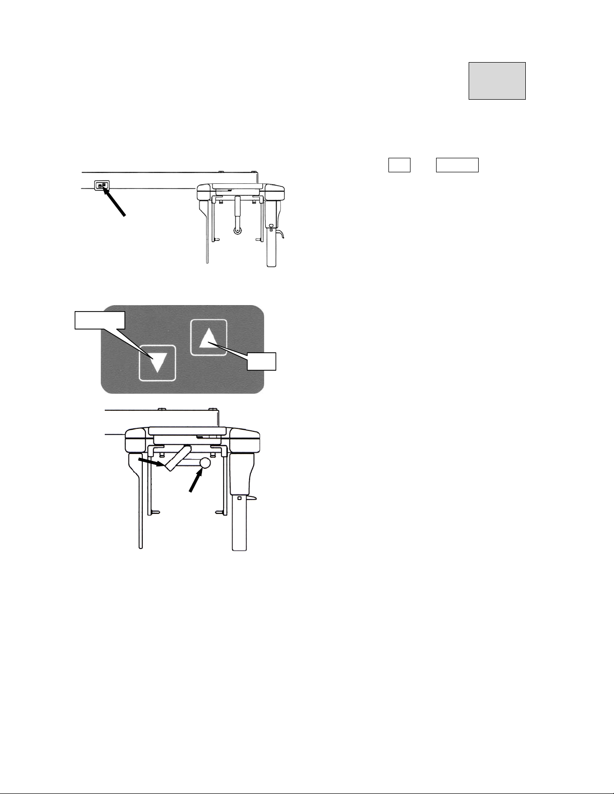
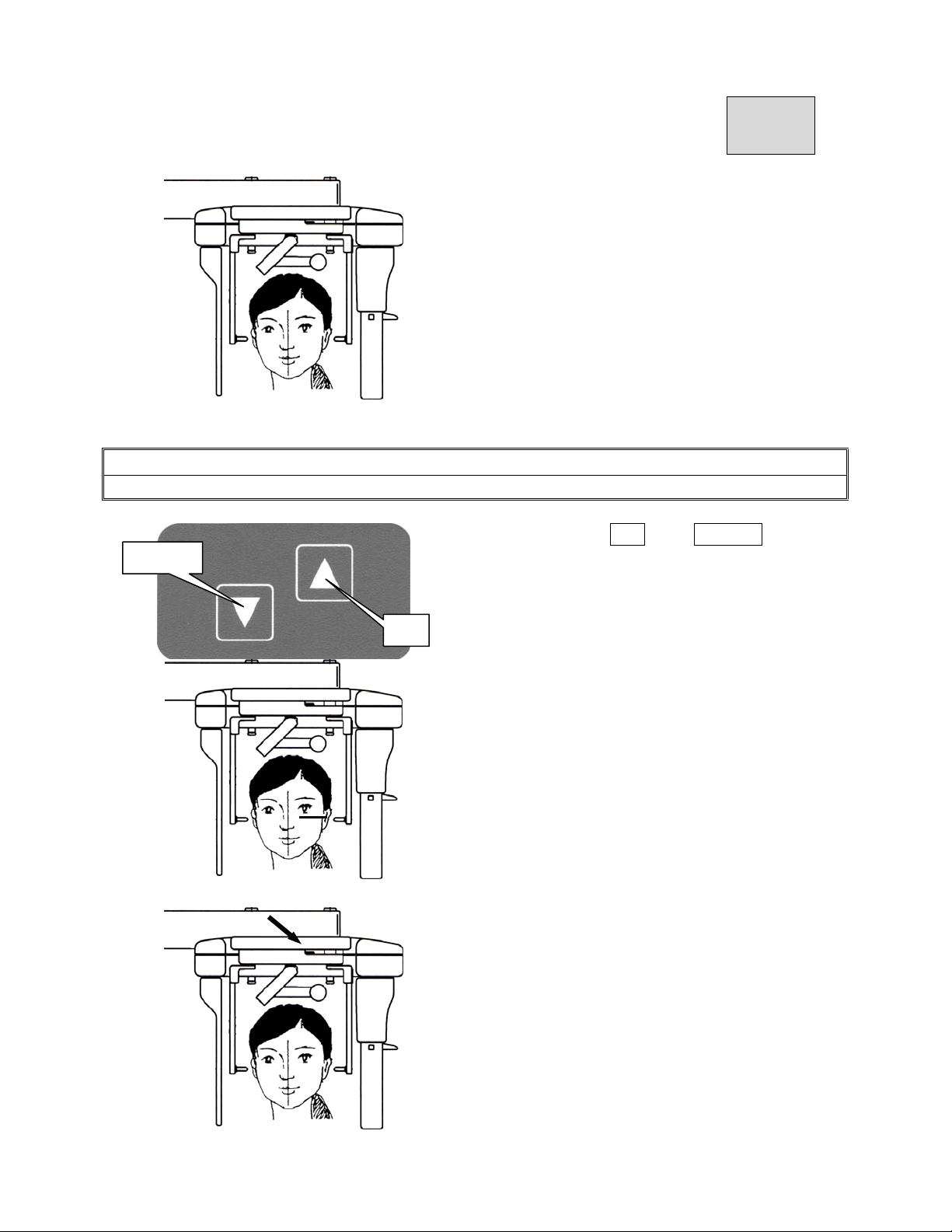
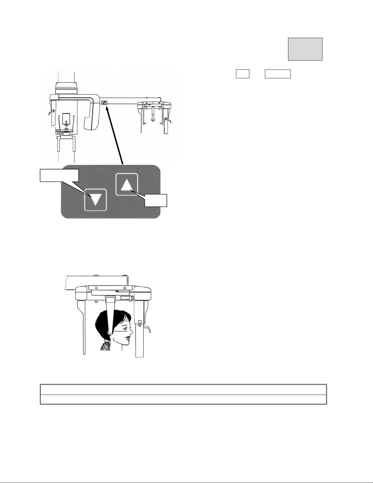
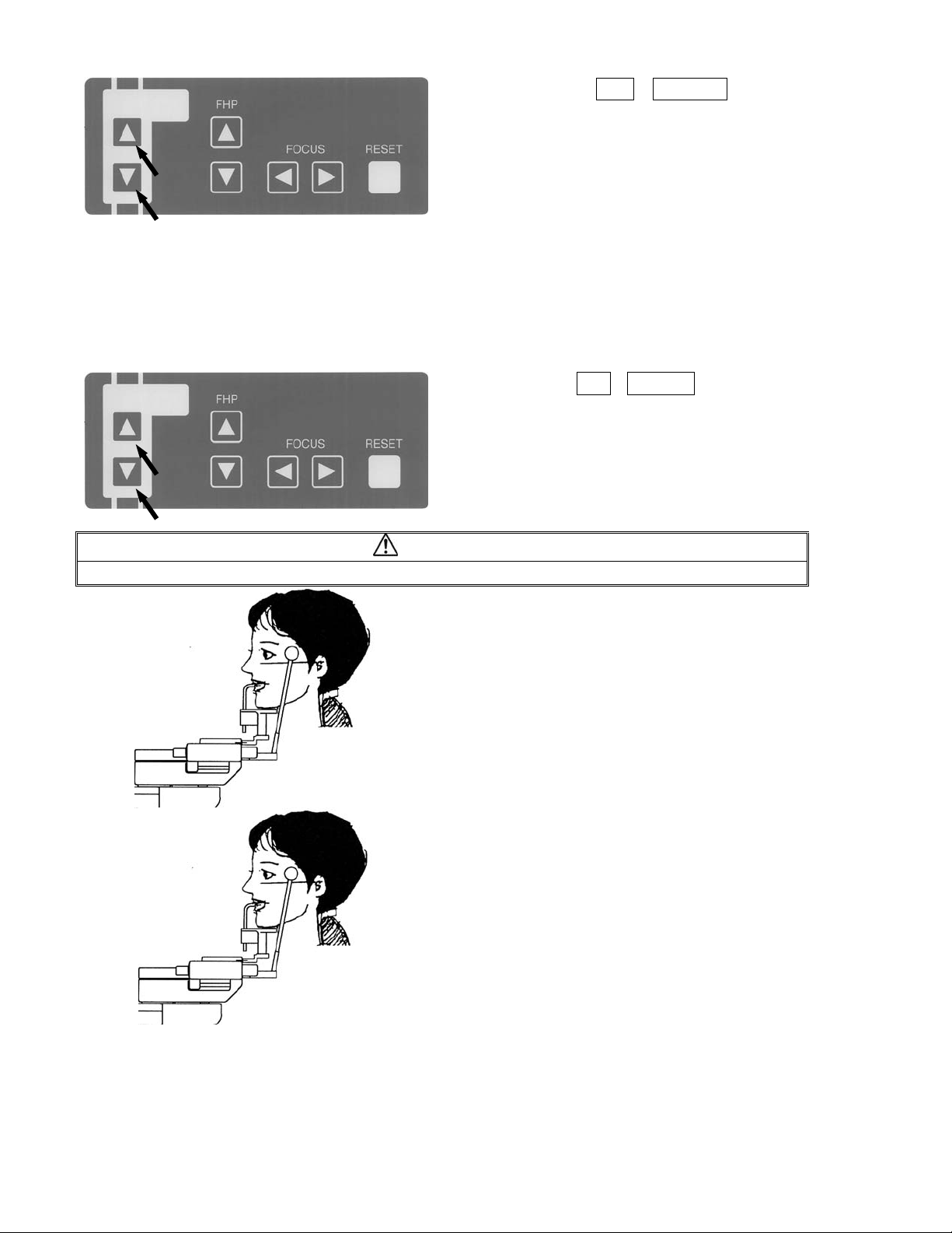
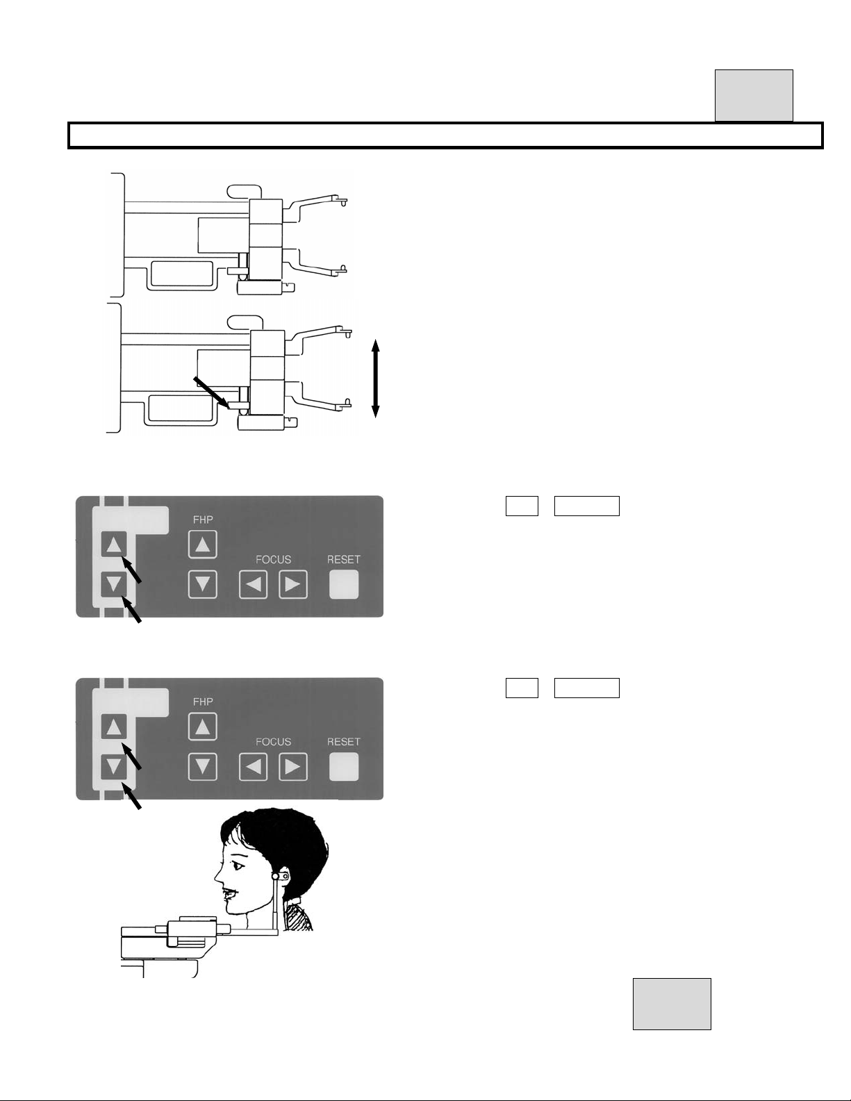
①Push either of UP or DOWN key of
Cephalo ARM Up-Down Panel, and move
Sliding Unit up and down to align position
of Ear Rod to near of external auditory
foramen.
DOWN
UP
③ Take fitting part of forehead and pull
forward.
④ Take fitting part of forehead by agley
and collapse it.
Instruct a patient “Stand behind Cephalo ARM with both feet under center of
Cephalo stat and by extending cervical vertebrae and back muscle.”.
Page 6
B02-T151 15
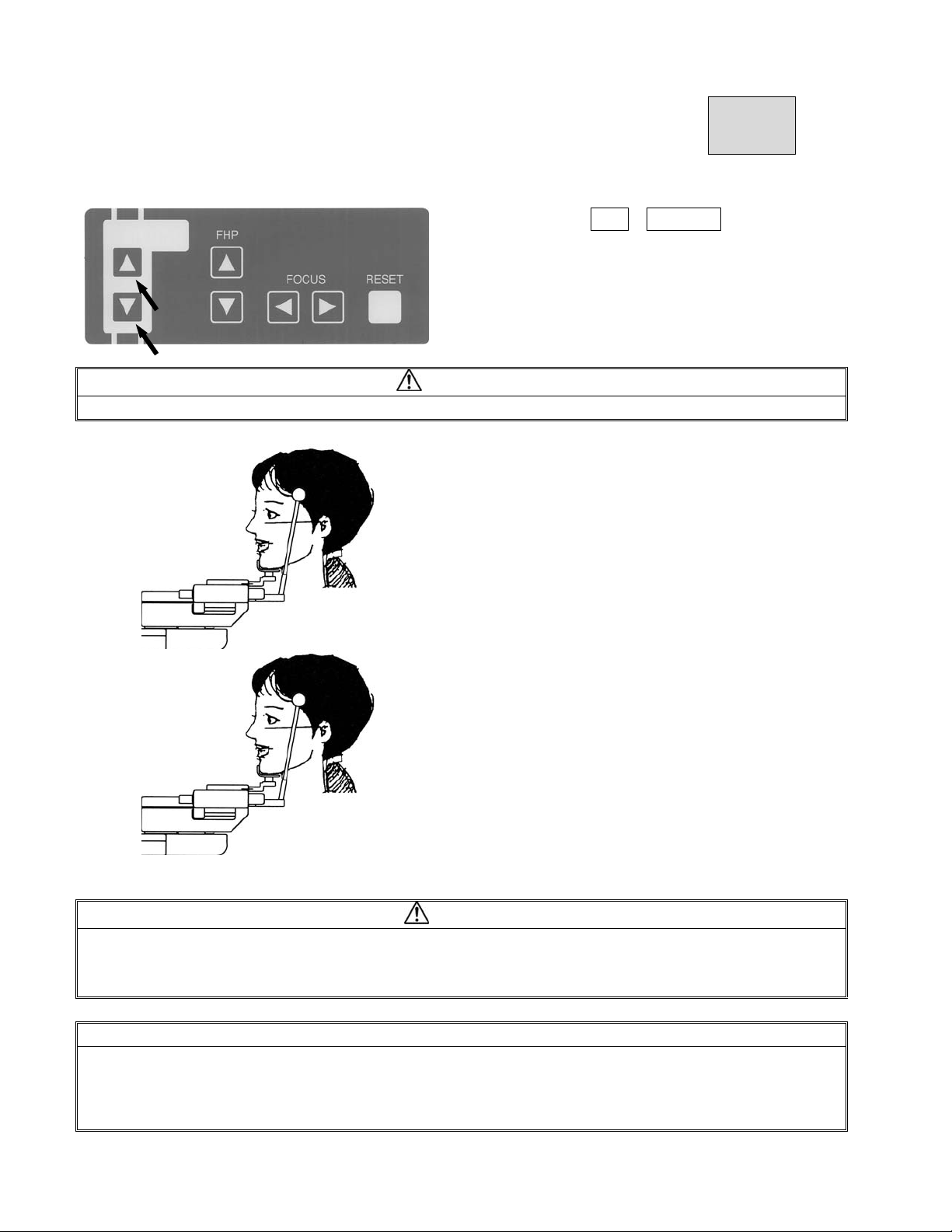
CAUTION
Pay enough attention to safety of a patient when Sliding Unit is moved up and down.
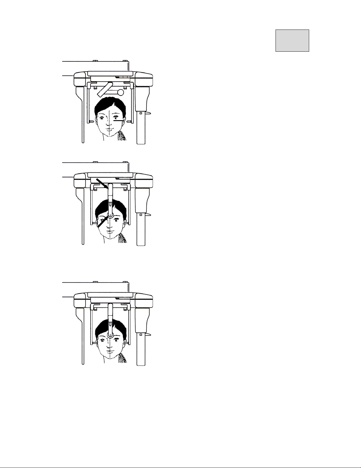
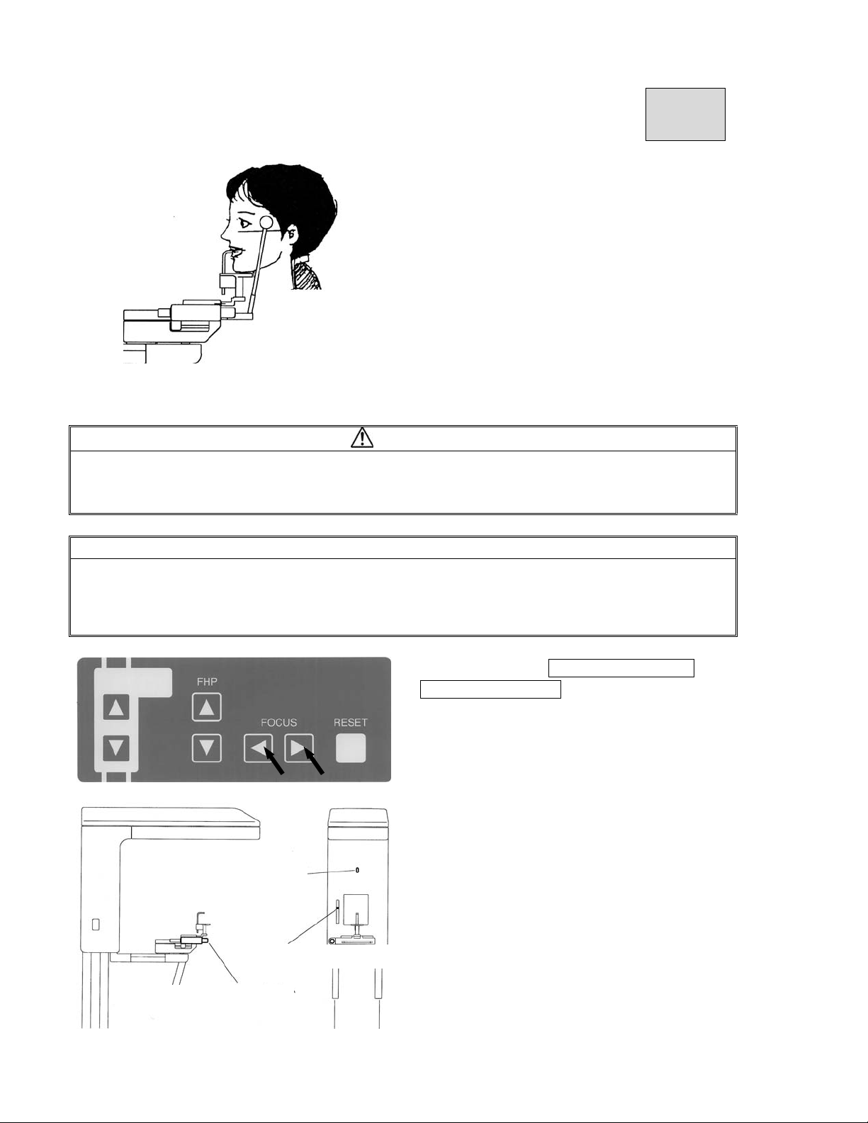
①Push either of UP or DOWN key ofU
DOWN
UP
p and down Movement Panel on CephaloAR
M to insert ear rod into external auditoryfora
men of a patient with fine adjustment.
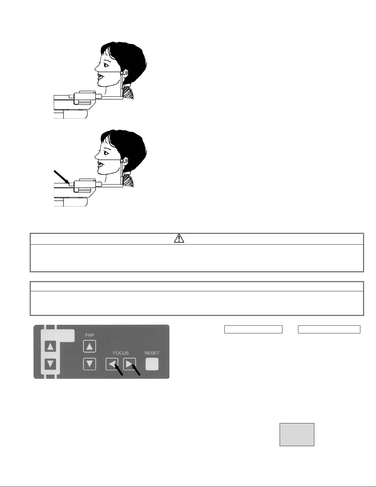
②Make Frankfort Plane of a patient ho
rizontally.
③Move ear rod open-close Lever on Cephalo
stat to close Ear Rod and insert Ear Rod i
n to external auditory foramen of a patient
lightly and then fit Ear Rod.
Page 7
B02-T151 15
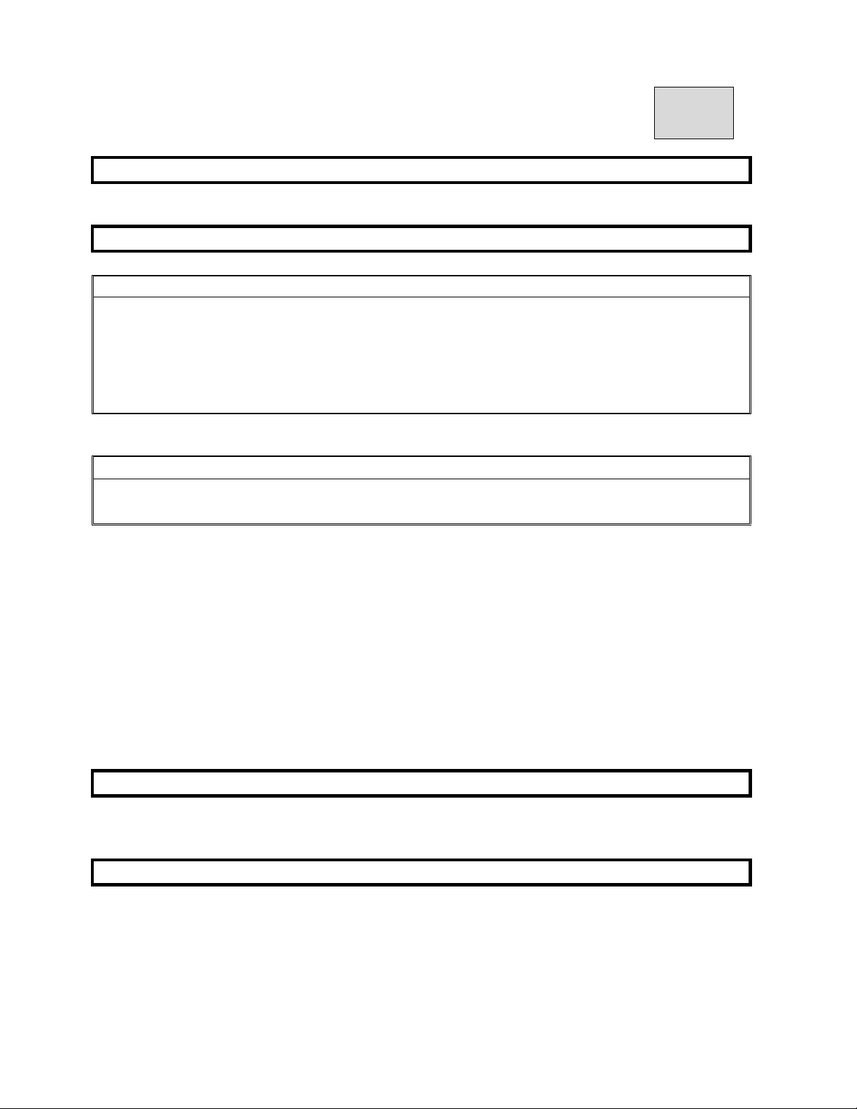
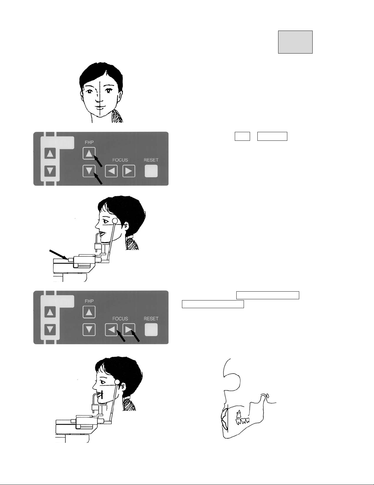
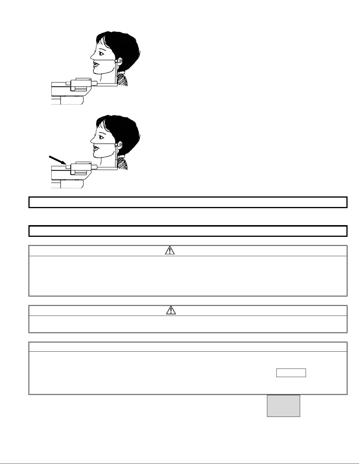
④After confirmation that Frankfort Plane of a p
atient is horizontal, close Ear Rod to fix him
certainly.
⑤Take a attaching portion of fitting part of
forehead and move to vertically.
Return to satart position.
⑥Move fitting part of forehead and align
patient’s forehead position.
⑦Take and move a attaching portion of
fitting part of forehead and put it to
patient’s forehead.
Page 8
B02-T151 15
5.Ready ON
Refer to 11.Operation Procedure for Panorama
6.X-ray Exposure
WARNING
1. Other people excepting a patient and an assistant should be outside of X-ray room while X-ray
is irradiated.
2.Operate “Exposure Switch” outside of X-ray room.
3.Keep to observe a patient and an assistant while X-ray is irradiated, and release Exposure
switch if any trouble might happen.
4.An operator instructs a patient not to move during exposure.
NOTE
1.Deadman system is applied to exposure switch. When the exposure switch is released, X-ray
irradiation and rotation of ARM Unit will be stopped.
6.1.Keep to push exposure switch until end of exposure.
6.2.X-RAY is kept to indicated and buzzer keeps to sound during exposure.
6.3.After exposure is finished, X-RAY indication will be lighted OFF, and buzzer will
stop to sound and ARM Unit will stop to rotate at the same time.
*Refer to section 11. Operation procedure for Panorama
7.COOLING TIME
Refer to 11.Operation Procedure for Panorama 9.COOLING TIME
8.Release of a patient
Page 9
B02-T151 15
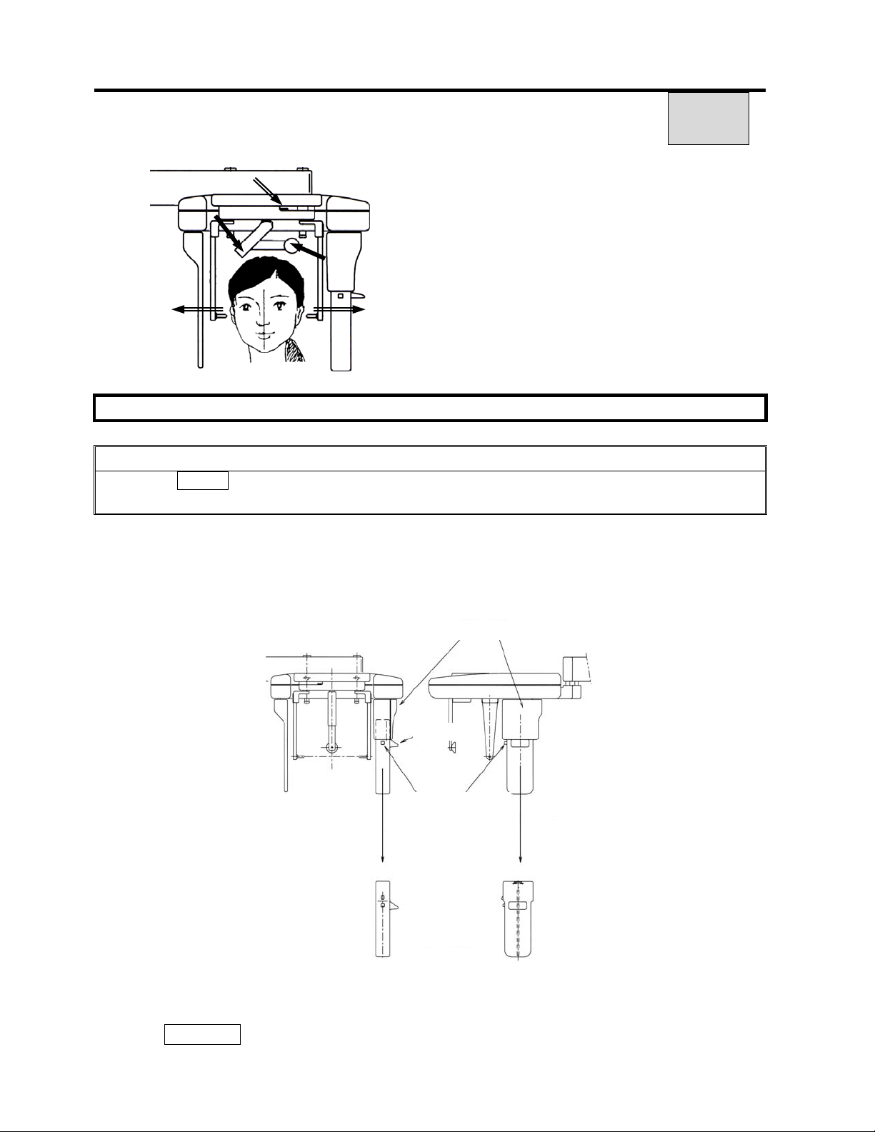
① Move open and close lever of Cephalo.
Open ear rod maximally.
② Take fitting part of forehead and pull
forward.
③ Take fitting part of forehead by agley
and collapse it.
9.Returning ARM Unit to Panoramic Exposure Position
CAUTION
When push RESET key on exposure display, ARM Unit starts to rotate.
Move away from rotation area of ARM Unit not by touching ARM Unit.
①Remove CCD sensor
Hold CCD sensor by left hand and raise falling prevention’s hook by right hand then
push hook release.
After release of hook, down CCD sensor below and remove it.
Sensor holder
Knob
Release of hook
Sensor unit
② Attach CCD sensor to Panorama
Refer to 11.Operation Procedure for Panorama and 1.Preparation for exposure.
③ Click RESET key on exposure display.
Page 10

B02-T151 15
④ ARM assy will move to start position for Panorama and stop automatically.
10.Confirm finish of cooling time
Refer to 11.Operation Procedure for Panorama
11.Turning Power OFF
Refer to 11.Operation Procedure for Panorama
Page 11
2-T151 16
16.Operation Procedures for Cephalo Front
(PA)
1. Learn the Panoramic radiographic operation procedures well. You can utilize Panoramic
operating procedures for other modes.
2. If procedures are the same as the ones of Panorama, explanations of operation
procedures in other modes are omitted. If you have any questions, Refer to operation
procedures for Panorama.
1.Preparation for the exposure
Please refer to preparation procedure of Cephalo Lateral (15)
2.Turning power ON
3. Exposure Setting Screen
Click either “Import” or “Scan” from diagnostic
software / imaging software.
If the power of the equipment is ON,
click OK.
f you receive the message「Equipment is not at
the original position. Push the RESET button.」
Then click the「RESET button」.
Page 12
2-T151 16
Setting the exposure mode
⑥Setting kV(tube voltage)・mA(tube current)
Refer to article 17 for Cephalo Front exposure condition and setting exposure condition.
Click Cephalo Front icon.
After select, icon will be changed to black.
Setting kV
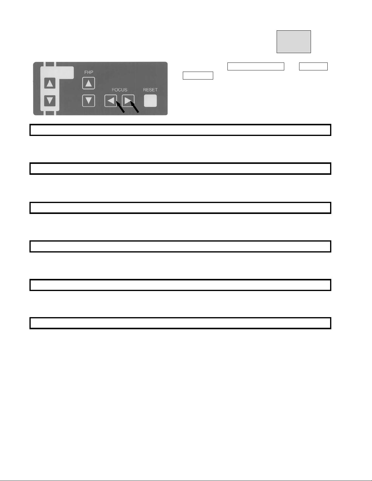
Click and select right side of kV ▲(UP)・
or ▼(DOWN).
Setting mA
Click and select right side of mA ▲(UP)・
or ▼(DOWN).
Or click upper right patient display.
In this case, depend on patient, adjustment of
kV・mA will be necessary
4.Patient Positioning
4.1.Aling Ear Rod with exposure direction
NOTE
If Ear Rod is rotated by holding Ear Rod, it might happen that alignment of Ear Rod
might be changed.
When Ear Rod is rotated, be sure to hold the fixing portion of Ear Rod.
Page 13
2-T151 16
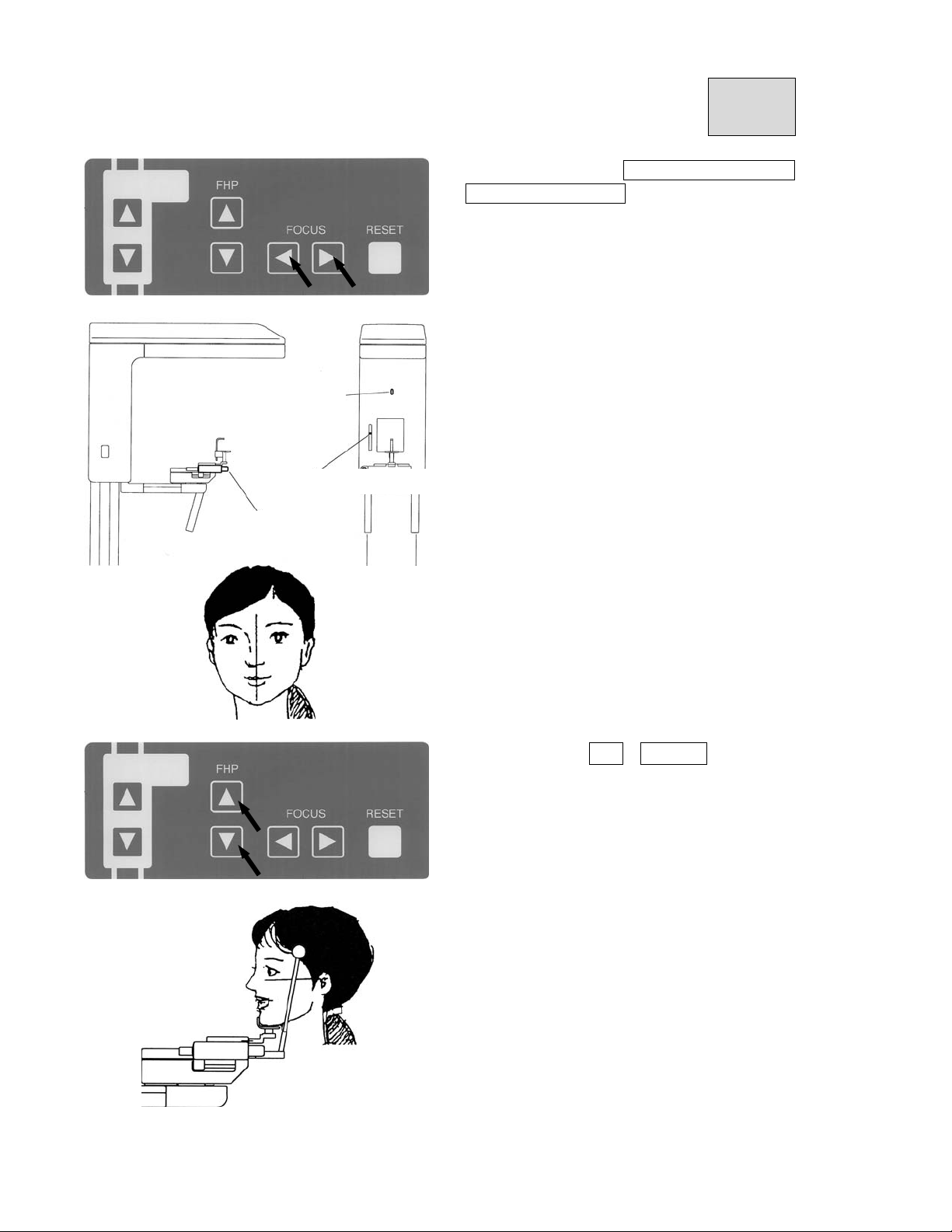
① Rotate Ear Rod by holding the fixing
portion of Ear Rod, align Ear Rod to
exposure direction of Cephalo Front.
②Move Open-Close Lever for Ear Rod of
Cephalo stat to open Ear Rod maximally.
③Align Nasion Pad horizontally.
4.2.Put X-ray protector apron on a patient and an assistant.
4.3.Guide a patient near to the equipment.
Page 14
2-T151 16
*Push either of UP or DOWN key of
Cephalo ARM Up-Down Panel, and move
Sliding Unit up and down to align position
of Ear Rod to near of external auditory
foramen.
DOWN
UP
4.4.Instruct a patient “Stand behind Cephalo ARM with both feet under center of
Cephalo stat and by extending cervical vertebrae and back muscle.”.
4.5.Positioning of patient.
CAUTION
Pay enough attention to safety of a patient when Sliding Unit is moved up and down.
Page 15
2-T151 16
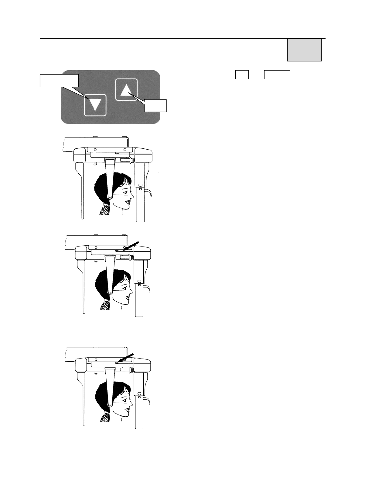
③Push either of UP or DOWN key of
DOWN
Up and down Movement Panel on Cephalo
ARM to insert ear rod into external auditory
UP
foramen of a patient with fine adjustment.
④Make Frankfort Plane of a patient
horizontally.
⑤Move ear rod open-close Lever on Cephalo
stat to close Ear Rod and insert ear rod
in to external auditory foramen of a patient
lightly and then fit Ear Rod.
④After confirmation that Frankfort Plane of a
patient is horizontal, close Ear Rod to fix
him certainly.
Page 16

2-T151 16
5.Ready ON
Refer to 11.Operation Procedure for Panorama
6.X-ray Exposure
Refer to 15. Operation procedure for Cephalo (LA)
7.COOLING TIME
Refer to 11.Operation Procedure for Panorama
8.Release of a patient
Refer to 15.Operation Procedure for Cephalo (LA)
9.Returning ARM Unit to Panoramic Exposure Position
Refer to 15.Operation Procedure for Cephalo (LA)
10.Confirm finish of cooling time
Refer to 11.Operation Procedure for Panorama
11.Turning Power OFF
Refer to 11.Operation Procedure for Panorama 14.Turning Power OFF.
Page 17
B02-T151 17
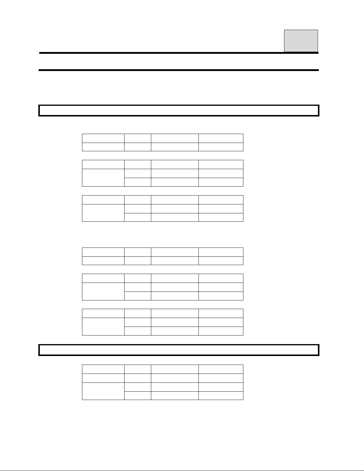
17.Table of Exposure Settings
Set exposure factors by consideration of size, age, bone density, etc.
of a patient.
1.Panorama
1.1.Exposure time 12sec
1)Panorama Child:CHILD ORBIT
A G E S E X
Child
2)Panorama Adult:ADULT ORBIT
A G E S E X
Adult
3)Orthoradial Orbit:ORTHO ORBIT
A G E S E X
Adult
1.2.
1)Panorama Child:CHILD ORBIT
2)Panorama Adult:ADULT ORBIT
3)Orthoradial Orbit:ORTHO ORBIT
Exposure time 7sec
A G E S E X
Child
A G E S E X
Adult
A G E S E X
Adult
- 60 8
Female
Male
Female
Male
- 60 8
Female
Male
Female
Male
kV mA
kV mA
62 8
64 8
kV mA
62 8
64 8
kV mA
kV mA
62 8
64 8
kV mA
62 8
64 8
2.Maxillary Sinus Radiography
A G E S E X
Child
Adult
-
Female
Male
kV mA
60
62 8
64 8
8
Page 18
B02-T151 17
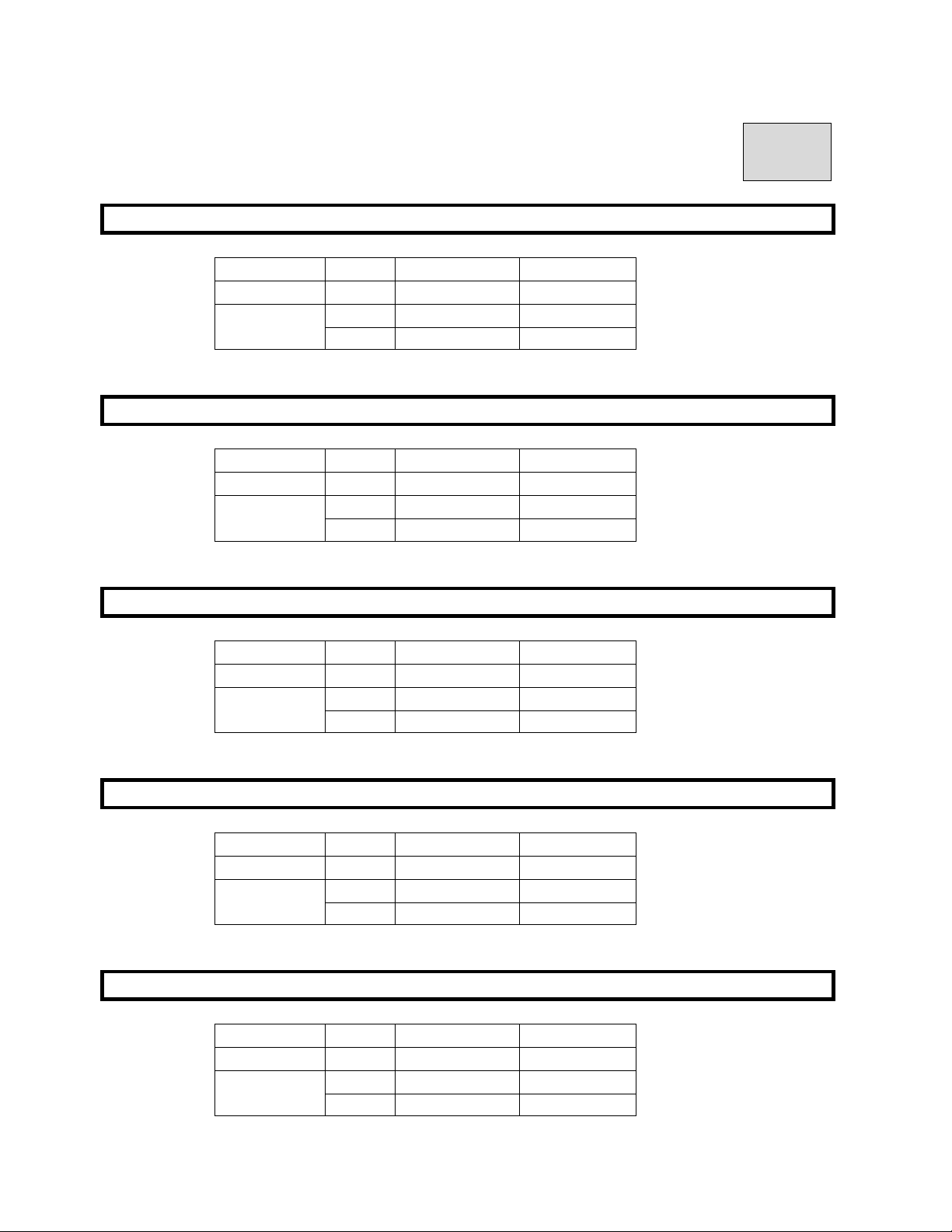
3.TMJ Lateral (4 sections)
A G E S E X
Child
Adult
-
Female
Male
kV mA
62
10
64 10
66 10
4.TMJ Front (2 sections)
A G E S E X
Child
Adult
-
Female
Male
kV mA
62
10
64 10
64 10
5.Cephalo Lateral (LA) normal exposure
A G E S E X
Child
Adult
-
Female
Male
kV mA
86
88 12
90 12
6.Cephalo Lateral (LA) short time exposure
A G E S E X
Child
Adult
-
Female
Male
kV mA
86
88 12
90 12
7.Cephalo Front (PA)
A G E S E X
Child
Adult
-
Female
Male
kV mA
86
88 12
90 12
12
12
12
Page 19

B02-T151 18
18.Magnification of Image
Radiographic Mode Orbit Magnification
PANORAMA :PANORAMA
MS
TMJ
CEPHALO
:Maxillary Sinus
:TMJ
:CEPHALO
CHILD ORBIT
ADULT ORBIT
ORTHO ORBIT
LA 4SECTION :Lateral (LA)
PA 2SECTION :Front (PA)
LA :Lateral (LA)
PA :Front (PA)
:Child
:Adult
:Ortho
:Maxillary Sinus
1.24~1.34
1.21~1.32
1.23~1.36
1.20~1.22
About 1.24
About 1.88
1.1
1.1
Page 20
B02-T151 19
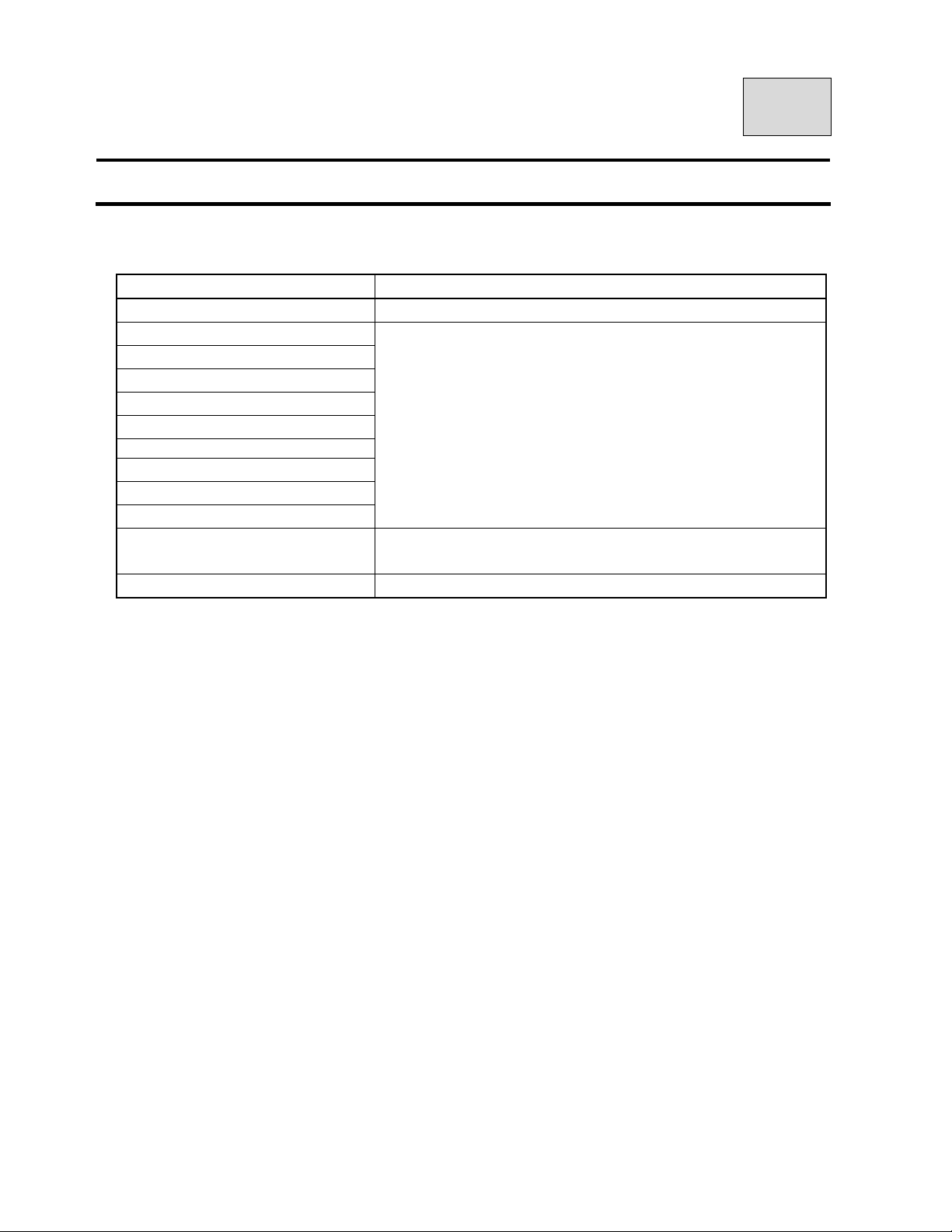
19.DAILY MAINTENANCE
Cleaning and Disinfection
Parts How to maintenance
Bite Blocks (For Panorama)
Head Holding Rods
Ear Rods (TMJ Lateral 4 sections)
Ear Rods (TMJ Front 2 sections)
Chinrest (Panorama)
Chinrest (Maxillary Sinus)
Nasion Pad
EAR Rods (For Cephalo)
FOREHEAD REST (For Cephalo)
All other parts which patients touch.
All other parts which operator touch.
Outside cover of the equipment
Sterilize by AUTO-CLAVE after exposure(s) of each patient.
Make enough disinfection with alcohol for medical use, of which
alcohol degree is over 76%. after exposure of each patient
Make enough disinfection with alcohol for medical use, of which
alcohol degree is over 76%, at end of daily operation.
Wipe equipment with a dry cloth at end of daily operation.
Page 21
B02-T151 20
20. Trouble Shooting
1.POWER can not be turned ON
Check Treatment
Is breaker turned on? Turn breaker on.
Is power plug connected to outlet? Connect power plug.
2.READY can not be turned on
Check Treatment
Is positioning of ARM at starting place? Depress RESET key.
3.Error message on PC display
Treat by following message on display.
Display
Motor of first collimator error. Depress RESET.
Head motor error. Depress RESET button.
Invertor error. Depress RESET button.
Vessel temperature error. Depress RESET button.
Motor of Y axis error. Depress RESET button
Motor of rotation error. Depress RESET button
Motor of indicator error. Depress RESET button
Motor of cephalo error. Depress RESET button
X-ray SW error. Depress RESET button
Communication error between MAIN CPU-MOTOR and CPU. Depress RESET button
Communication error between PC and MAIN CPU. Depress RESET button
If you can not solve problem by treatment of following display, turn off the power
and turn on the power again.
* When the trouble cannot be resolved, turn power of the equipment OFF, and remove electric
power socket from electric outlet, and call to our agent or our office where are near you.
In case that CCD Sensor has a problem
Turn the power of the PC off
Turn the power of the Panoramic radiograph off.
Turn the power of the Panoramic radiograph on again
Turn the power of the PC on again and restart the PC
Check the condition of LED (green color)
If the green LED is not blinking, check the connection between the PC and the Sensor unit
Page 22
B02-T151 21
21.MAINTENANCE
Warning
High voltage is applied to inside of the equipment. Do not open the cover by yourself.
Before asking for a repair, turn the power of the equipment OFF, and unplug from the power outlet.
After unplugged the equipment, wait for 10 minutes before starting a service work.
Special knowledge and special measuring tools are required to check this equipment.
To ensure that X-ray unit functions within the manufacturer’s specifications and remains in compliance with
Standards, daily checking (by eyes) and a periodic maintenance by the dealer service personnel are
recommended.
Maintenance by service personnel 1-2 times/year
Check Item Purpose Action
Method
Electricity
Condition
External
Appearance
Installation place
Safety Test for
Electric Shock
Movement
Accuracy
of the equipment
Check voltage range
External Appearance
Inside of the equipment Check stain and dust
Temperature & Humidity
Level of floor Check the influence to the equipment
The Installation condition
of the equipment
Check obstacles
Rust
Insulation Resistance
Leaked current from the
outer cover
Earthing resistance
Resistance of the Earth
wire
Power Circuit voltage Check the voltage of the power circuit
Check Radiographic
Circuit
Check Control Circuit Check the movements of operating sequences
Accuracy of the
Positioning Mechanism
Check the Movement of
the Protection Circuit
Check display circuit Check the functions of display circuit
Check whether incoming voltage is within the
equipment’s requirement or not.
A) Deformation, scratches.
B) Warning Labels
Check compatibility of the environmental
conditions to operate the equipment
Check vibration and movement stability of the
equipment
Make sure that there are no obstacles within the
movement range of the equipment
Check the condition of the rust. Evaluate the
influence to the safety.
Check the resistance between a power line and
the earth
Check the current which is leaked from
the outer cover of the equipment to the earth
Check the resistance value between an exposed
metal and the earth
Resistance between the earth terminal and the
earthing point
Check the wave shape and the setting values of
the radiographic circuit
Check the deterioration of the positioning
mechanism
Check the setting values of the protection circuit.
Check the movement of the protection circuit.
●
◎
◎
●
●
●
●
◎
◎
●
●
●
●
●
●
●
●
●
●
Page 23

B02-T151 21
Check Item Purpose Action
Method
Display during an
exposure
X-ray Generator
Radiographic
mechanism
Sliding mechanism
X-ray output
Accessories
Check irradiation of
X-ray and “X-RAY ON”
display are in sync
X-ray tube Check the leakage of insulation oil
Low voltage cables Check wear, damage, tension, and twist
Cone Check looseness, transformation, and damage
Filter Check transformation and damage
Slit Plate (Collimator)
Movement of the
ROTATION ARM ASSY
Patient Positioning
Mechanism
Positioning beams Check the brightness and the positioning accuracy
Wire Rope
Upward / downward
movements
Drop prevention
mechanism
X-ray Tube Voltage Check X-ray Tube voltage
X-ray Tube Current Check X-ray Tube current
Exposure Time Check exposure time
Check this while X-ray is irradiated.
Check off-alignment of exposure field. Confirm the
exposure width
Check slip, abnormal sound, and stopping
accuracy
Play, looseness, operational performance, and
safetyness
Check cut, check the wire is securely connected
to the terminal
Check smoothness of the movement
Check safety mechanism works properly
Intensifying Screen Check crack and scratch
Film Cassette Check crack and scratch
Checking Methods
◎:Check by eyes during a daily operation
●:Check by a service personnel.
◎
◎
◎
◎
◎
●
◎
◎
◎
●
◎
●
●
●
●
◎
◎
Page 24
B02-T151 22
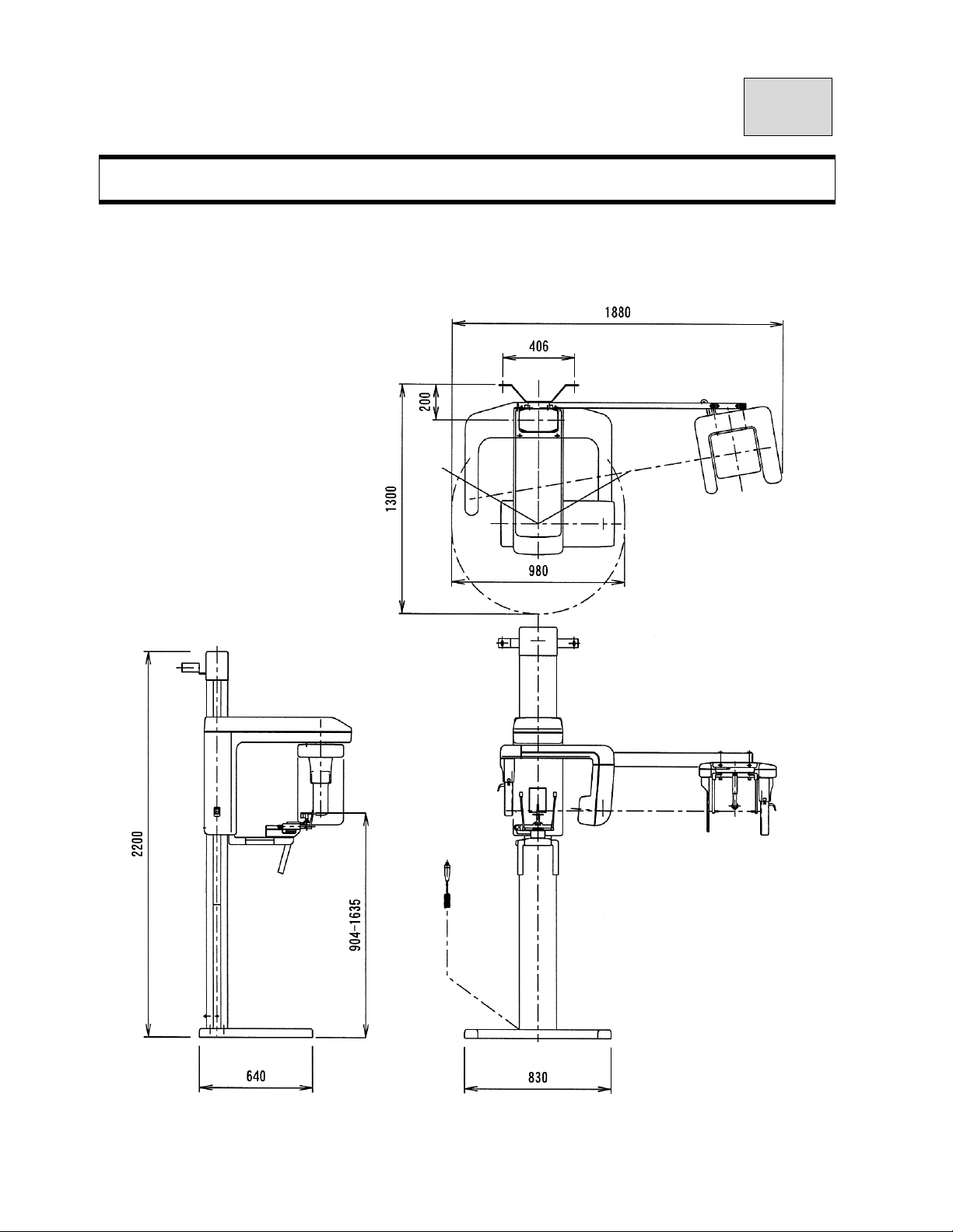
22.Physical Dimensions
BelmaX CM
Page 25

B02-T151 23
23.Technical data
1.Wall Bracket.
The distance between the column and a wall is 6.1” (155 mm).
2.Compliance with International Standards
ANE-BEL, ANA-BEL CM complies with the following standards
IEC 60601-2-7 (1998)
IEC 60601-2-28(1993-03)
IEC 60601-2-32(1994-03)
3.Classification
1.According to the type of protection against electric shock
a) Equipment energized from external electrical power source.
Class I equipment
2.According to the degree of protection against electric shock
Type B applied part
3.Protection against Ingress of water
Ordinary
4.Equipment not suitable for use in the presence of a FLAMMABLE ANAESTHETIC MIXTURE WIT
H AIR OR WITH OXYGEN OR NITROUS OXIDE
5.According to the mode of operation:
Continuous Operation with Short-Time Loading
6. Duty cycle:
Exposure Time: 12 sec, Cooling Time: 90 sec
4.Remaining Risk
1.Occurrence of the excesse X-ray dosage due to malfunction of software during exposure
Signal to Watch Dog IC (works to reset if the signal is in the same condition over 1.6 sec.) o
bserves the operating condition of the software.
2.If excessive X ray is irradiated due to the mechanical malfunction, immediately turn the X-RAY SWITCH OFF.
to stop the irradiation.
3.Operator instructs a patient not to move until the movement of the ROTATION ARM stops during
a RESET process.
4.ANA-BEL monitors the temperature of the X-ray generator from READ ON to the end of the exposure.
If X-Ray generator malfunctions due to the unusual temperature in X-ray tube, radiography will be
terminated and ERROR will be displayed.
5.Operator instructs a patient not to move during an exposure.
Also, operator should pay attention to a patient, an assistant, and the equipment during an exposure.
Page 26

B02-T151 23
5.Environmental condition to operate the equipment is as follows.
Environmental condition to operate the equipment
The temperature: 41~95F (5~35℃)
The humidity : 30-85%
The atmospheric pressure: 700-1060hpa
6.The environmental condition to transport the equipment is as follows.
Environment to transport the equipment
The temperature: 14~140F (-10~60℃)
The humidity : 30-85%
The atmospheric pressure: 700-1060hpa
7.X-ray Generator
1.Maximum electric output
Maximum X-ray tube voltage: 90kV
Maximum X-ray tube electric current: 12mA
2.Nominal maximum electric power for output of 90kV, 12mA.
1.08kW
3.Standard Tube Voltage, Current and Time
120mAs(75kV、10mA、12sec)
4.Minimum Tube Current and Time
24mAs(2mA、12sec)
5.Nominal Capacity of Anode Input
1.75kW
6.Maximum Capacity of Anode Heat
35kJ(50kHU)
7.Material of X-ray Tube Anode
Tungsten
8.target angle of X-ray Tube
5°
9.Angle of X-ray Tube Focus Angle
5°
10.Size of X-ray Tube Focus
0.5×0.5(mm)
11.Characteristic Filtration of X-ray Tube
0.8mmAl
12.Nominal Tube Voltage of X-ray Tube
50~100kV
13.Rating of X-ray Tube Filament
3.5~4.9V 3.5A
Refer to Characteristic Drawing of Emission for Cathode
14.Supplied Voltage of Primary Side for 50-100kV Output
About 150 Vp (PWM)
15.Weight of X-ray Generator About 7.13 kg
Page 27

B02-T151 23
16.Leaked Dose of the X-ray Generator
Refer to the attached document paper.
Loading Factor to measure leakage of X-ray Generator: 90kV, 12mA, 20sec
17.Type of X-ray Generator
CLASS I
18.Standard Angle to assemble X-ray Generator
Horizontal / perpendicular
19.Target Angle to assemble X-ray Generator
5°
20.Precision to install focus of X-ray Generator at time of construction of
X-ray Generator
±0.5mm
21.Size of the focus at time of installation of X-ray Generator
0.5×0.5(mm)
22.Duty Cycle
Cooli ng tim e f or this X-ray Generator is 90 seconds to avoid the accumulation of excessive heat. X-RAY
operation is unavailable for 90 seconds after each exposure.
8.Aluminum equivalent
Name of part Aluminum equivalent
Filter 0.8mmAl
Sliding Unit Cover 2.0mmAl
Ear Rod(TMJ 1 & 2) 0.2mmAl
Head Holder 0.2mmAl
Film Cassette 1.2mmAl
Intensifying Screen 3.0mmAl
Bite Block 1.0mmAl
9.Rating of Line Switch
250V, 15A
10.Maximum Energy Input per 1 hour
1728mAs / h
11.Rotation Speed of ARM
0.85km/h.
12.Rotation Force of ARM
3.7kgf.
Page 28

B02-T151 23
13.Staments of Reference Loading Condition
90kV, 12mA, 12sec (ANA-BEL)
90kV, 12mA, 3.2sec (ANA-BEL CM)
14.Laser Marking
Class : 2 products (IEC60825-1: 2001)
Wave Length: 670mm
Standard : 1mW
15.Line impedance
0.3Ω
Page 29

B02-T151 24
24.Contact Information
Belmont Equipment
A Division of TAKARA BELMONT USA, Inc.
101 Belmont Drive
Somerset, NJ 08873
Toll Free (800) 223-1192
Toll Free Fax (800) 280-7504
www.belmontequip.com
TAKARA COMPANY, CANADA, LTD.
2706 South Sheridan Way
Mississauga, Ontario, Canada L5J 2M4
Toll Free (800) 268-5351
Fax (905) 822-6203
www.takarabelmont.ca
Page 30

B02-T151 25
25.Revision data of this manual
This manual was revised on JUL.2006.
The revised document number :B02-T145
Page 31

B02-T151
Thank you very much for purchasing our equipment Model BelmaX CM.
Please read this operation manual carefully before operation in order to use the X-Ray
machine properly and safely.
Page 32

B02-T151
CONTENTS
pages
01.INTRODUCTION
02.WARNING
03.Explanation of Equipment
04.Specifications
05.Standard Accessories
06.Name of each parts
07.Explanation of each parts
08.Exposure setting screen / Control Panel
09.Preparations before exposure
10.Flow Chart of Exposure Process
11.Operation Procedure for Panorama
12.Operation Procedure for Maxillary Sinus
13.Operation Procedure for TMJ Lateral (4 sections)
14.Operation Procedure for TMJ Front (2 sections)
15.Operation Procedure for Cephalo Lateral(LA)
16.Operation Procedure for Cephalo Front(PA)
17.Table of Exposure Factors
18.Magnification of Image
19.DAILY MAINTENANCE
2
3
2
2
1
2
2
4
2
1
14
6
7
6
9
6
2
1
1
Page 33

B02-T151
CONTENTS
20.Trouble Shooting and Error Code List
21.MAINTENANCE
22.Physical Dimensions
1
2
1
23.Technical data
24.Contact Information
25.Revision Record of this manual
4
1
1
Page 34

B02-T151 01
01.INTRODUCTION
1.Read this manual carefully when you use this equipment for the first time.
2.Be sure to observe warning sentences and forbidden matters at the operating time of the
equipment.
3.Read the operation manual from the beginning to the end.
Reading the operation manual from halfway migh t lead to misunder sta nding .
4.Read this manual again to confirm the portion in question if you have any questions.
5.Operation procedure of Panoramic radiograph is basis of X-ray radiograph.
Your can use this procedure for other radiograph (i.e. MS, TMJ)
6.Explanation of operation procedure of other radiograph are omitted, if the proced ures are same as the one
of Panoramic radiograph.
Refer to operation procedure of panoramic radiograph, if you have any questions about operating
procedures.
7.Discharge
Be sure to observe the contents of this operation manual.
Even if any trouble or an accident will happen due to wrong use, we will not be responsible
for them.
8.Warrantee Period
Warrantee period is two years after purchase of the equipment.
We will repair failure or defect by this warranty. This warranty is void when failure or defect is caused b y
conditions beyond the manufacturer’s control, such as damage resulting f rom mishandling, neglect, misuse,
improper maintenance, accident or alteration or repair by anyo ne other than Belmont or authorized Bel mont
dealer. See warrantee card for more information.
Operation condition.
9.Maintenance
Be sure to make proper maintenance of your equipment.
Maintenance responsibility of medical equipment lies on the user.
10.Period for repair and supplying parts
We will supply parts of the equipment for 10 years, after the manufacturing of this equipment is
discontinued.
11.
mark means “ Attention, consult accompanying documents ”.
Page 35

B02-T151 01
12.
mark means “ Protective earth(ground) “.
13.
mark means “ OFF (Power: disconnection from the mains) “.
14. mark means “ ON (Power: connection to the mains) “.
15.
mark means “Type B“ Applied part
16.No user serviceable items inside.
17.Conformability of indicated X-RAY requirement was determined in accordance with R10 sequences that
follows ISO497.
Page 36
B02-T151 02
02.WARNING
WARNING:
Always conform to the safety work standards.
Repair work for internal parts of the equipment involves high risk. This should be strictly conducted by an
authorized service personnel only.
NOTES:
Details of WARNING are stated as follows in this manual:
DANGER:
Ex p l a i n s dange r that may cause serious adverse effect to a human b ody.
WARNING:
Ex p l a i n s an instructio n where a personal injury or a physi cal damage may occur.
CAUTION:
Explains an instruction that should be observed for safety reasons.
NOTE:
States descriptions which serve to improve work efficiency and to help user to understand instructions in the manual.
DANGER
This equipment is electrical equipment. Do not splash water.
Such action causes an electric shock or a trouble of the equipment.
WARNING
Any user should not open any cover of the equipment.
WARNING
The management responsibility of use and maintenan ce of this equipment belongs to the user
The operation of this equipment is limited only to legally qualified persons.
User should not open the cover of the equipment.
Contact your dealer for service.
Page 37
B02-T151 02
WARNING
This equipment should be installed i n the X -ray roo m su rro und ed by wal ls that have over 1.0 mmPb lead equiva le nce.
The exposure switch sh ould be instal led outside of the X-ray ro om.
WARNING
When earthquake is warned, do not use the equipment.
After earthquake occurred, check the equipment and make sure the equipment works properly.
WARNING
This X-ray Unit may be dangerous to patient and operator, if safe exposure factors and operating instructions are not
observed.
WARNING
Do not put things in area where the equipment moves.
WARNING
Put a X-ray protective apron on the patient.
WARNING
Disinfect the area where a patient and an operator might touch after each exposure.
WARNING
Operator should pay attention to a patient when the Sliding Unit moves up and down.
WARNING
When the equipment is not used, turn off “Power SW“
WARNING
When the equipment has trouble, turn off“Power SW“.
Page 38
B02-T151 02
WARNING
During an X -R ay exposure, o nl y a patient and a helper ( who is permitted to enter by an ope ra tor) are allowed to
stay in X-Ray room.
The helper (hereinafter helper) in this manual, is defined as person who a doctor permits to assist a p at ien t w hi le
taking a X-ray radiograph.
WARNING
Do not press the exposure switch in the X-ray room.
Watch a patient and the equipment during an exposure.
When you encounter any trou bl e , immediately rele a se the ex po su r e s wit c h.
WARNING
LASER, DOT NOT STARE INTO BEAM, CLASS 2 LASER PRODUCT
1.Laser Beam is applied. For safety, instruct a patient not to look at the laser beam.
2.Before the beam is lightened, lower the Frankfort Line Beam to the bottom.
3.Do not set the beam to patient's eyes.
CAUTION
When the equipment and/or its' parts will be disposed, contact the dealer or our office.
CAUTION
Disposal Process:
Dispose used bite fork covers and films according to the disposal procedures indicated by each
manufacturer and the local code.
CAUTION
Do not turn the Rotation Arm by hands. It might cause trouble of the equipment.
CAUTION
Operator shall instruct a patient not to move while X-ray exposes.
Operator shall instruct a patient not to move until the movement of ARM is finished during RESET
movement.
CAUTION
The equipment shall be connected to the receptacle marked “Hospital Only” or “Hospital Grade”.
Page 39

B02-T151 03
03.Explanation of Equipment
1.Outline
BelmaX CM can take radiographs of Panorama, TMJ, Maxillary Sinus, and Cephalo.
2. Features
2.1.Radiograph with multiple orbits
Every kinds of Panoramic radiograph can be taken in the Maxilla-Facial radiograph
such as Panorama and TMJ.
2.2.Panoramic radiograph with less overlap of teeth
By the orthoradial panoramic mode, a panora mic rad iograph w ith less over lap can be taken .
2.3.High Frequency X-ray Generator
The X-ray generator with the High Frequency Inverter delivers high quality radiation. This enables
improved image quality while reducing radiation dose.
2.4.X-ray Tube with minute focus
Owing to the minute X-ray Tube focus of 0.5 x 0.5mm, sharp and clear image is achieved.
2.5.Versatile Combination of Exposure Factors
Tube voltage can be set from 60 kV to 90 kV by 1 kV step.
Tube current can be set at 2, 4, 6, 8, 10, and 12mA.
With wide range of exposure setting, BelmaX CM can get ideal radiograph for every type of patient.
2.6.Patient Positioning with 3 Beam Lines
Bright and Visible three laser beams make positioning very easy and accurate.
2.7.Adjustable Mirror for Patient Positioning
The Angle of the mirror can be changed, both patient and operator can easily check the patient
positioning.
2.8.Motorized Sliding Unit
The Motorized Sliding Unit enables smooth operation and fine adjustment for the precise
positioning.
3.Configuration
Equipment consists of below assemblies.
1. Mechanical Assemblies, 2. X-ray Generator, 3. X-ray Controller
4. Cephalo Assembly:
Page 40

B02-T151 03
4.Available Radiographic Modes
Panorama
TMJ Lateral
TMJ Front
Maxillary Sinus
Cephalo Lateral
Cephalo Front
Page 41
B02-T151 04
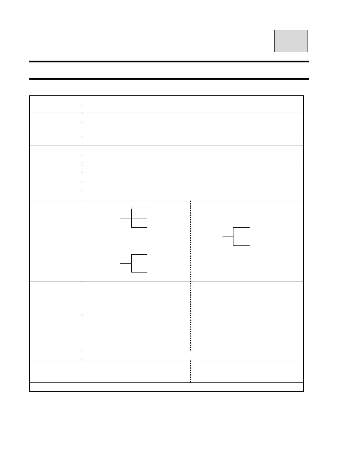
04.Specifications
Model
Input Power
Power
High Tension
Generator
Exposure Method Manual
Tube Voltage
Tube Current 2.4.6.8.10.12mA (2mA step)
X-ray Tube
Focal Spot
Total Filtration
CCD sensor Both as Panorama and Cephalo
Panoramic
Exposure Mode
Exposure Time
Magnification
Positioning Beam 3 beams
Positioning tools
Weight 417 lb(189 kg)
Maxillary Sinus
TMJ
Panorama
Maxillary Sinus
TMJ Lateral
TMJ Frontal
Panorama
Maxillary Sinus
TMJ Lateral
TMJ Frontal
Panorama・M axillary Sinus:
Chin Rest+ Head Holding Rod
TMJ Lateral・Frontal:Ea r Rod
Digital Panoramic and Cephalometric Radiograph BelmaX CM
(+/- 10%) 60Hz 1φ
2.0kW
0.5×0.5mm
Cephalo
Cephalo Lateral:2.9sec(short time mode)
4sec(normal time mode)
Frontal:3.2~5sec
Cephalo Lateral & Frontal: 1.1
Lateral
Frontal
―
:7sec/12sec
:8sec
:3.0sec(
:3.0sec(
:1.21~1.36
:1.2~1.22
:appr.1.24
:appr.1.88
120Vac
High Tension Generator (100kHz)
60kV~100kV (1kV step)
D-052SB(Toshiba)
2.5mmAl(Min)
Child
Adult
Orthoradial
Lateral
Frontal
×
4)
×
2)
Page 42

B02-T151 04
Environmental condition for Operation
Temperature : 41~95F (5~35℃)
Humidity : 30~85%
Pressure : 700~1060 hpa
Environmental condition for Storage
Temperature : 14~140F (-10~60℃)
Humidity : 10~95%
Pressure : 700~1060 hpa
Environmental condition for Transportation
Temperature : 14~140F (-10~60℃)
Humidity : 10~95%
Pressure : 700~1060 hpa
Page 43
B02-T151 05
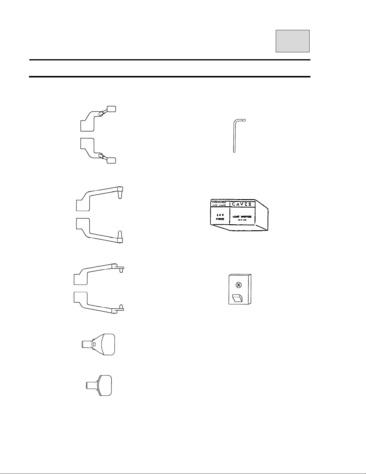
05.St andard Accessories
1. Head Holding Rods (Panorama)
(Maxillary Sinus)
2.Ear Rods (TMJ Lateral 4 sections) 7.Bite Fork Cover(Disposable)
6.Bite Fork (Panorama)
3.Ear Rods (TMJ Front 2 sections) 8.X-ray Switch Holder
4.Chinrest (Panorama)
5.Chinrest (Maxillary Sinus)
Page 44
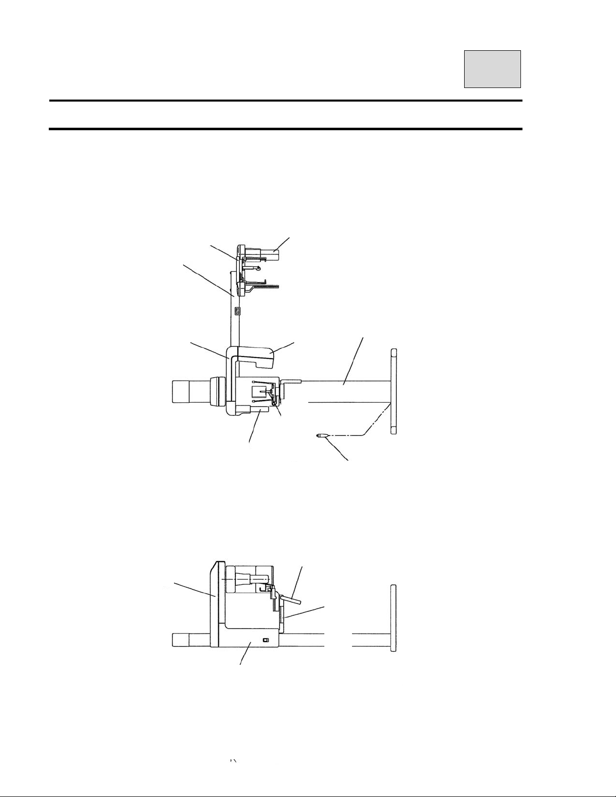
B02-T151 06
Y
Y
06.Name of each parts
BelmaX CM
Cephalo Stat
Cephalo arm
Arm ASS
Panorama sensor
Rotation unit
Sliding unit
Cephalo sensor
X-ray generator
Rest ASS
Grip
Pillar
X-ray switch
Beam operational panel
Page 45
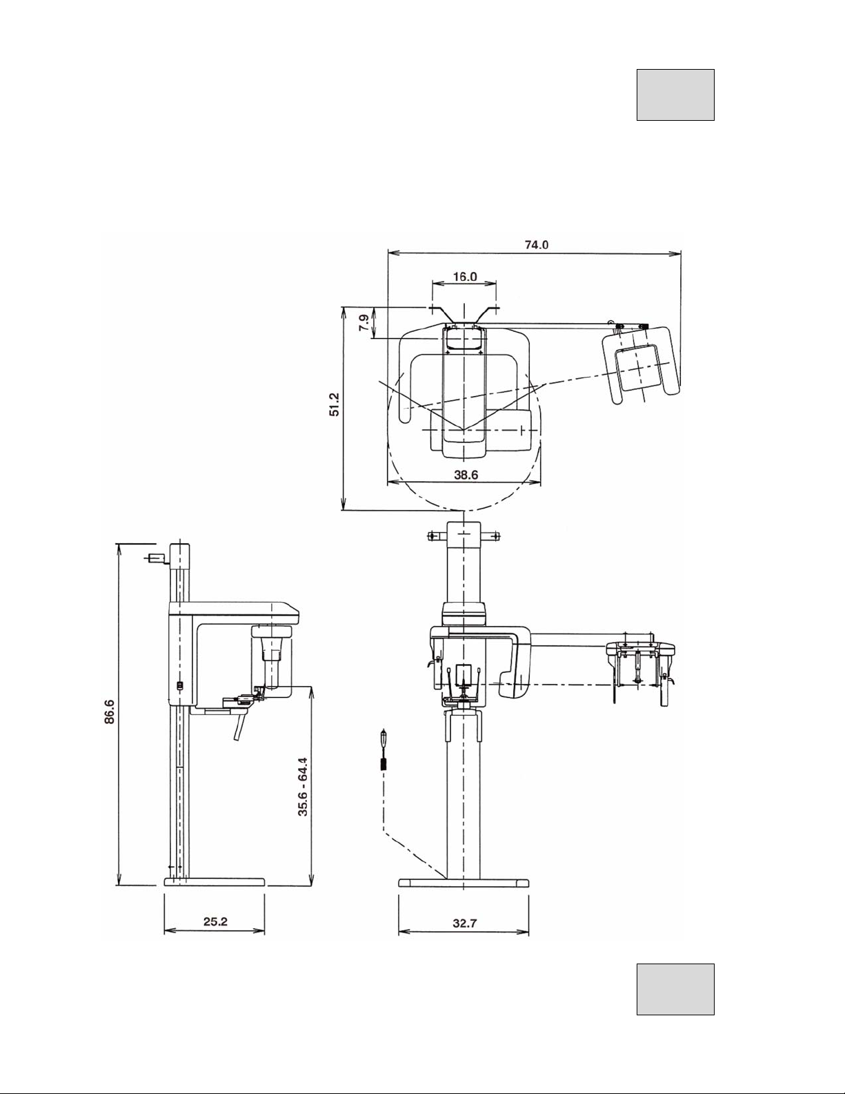
B02-T151 06
Dimensions
B02-T151 06
Page 46
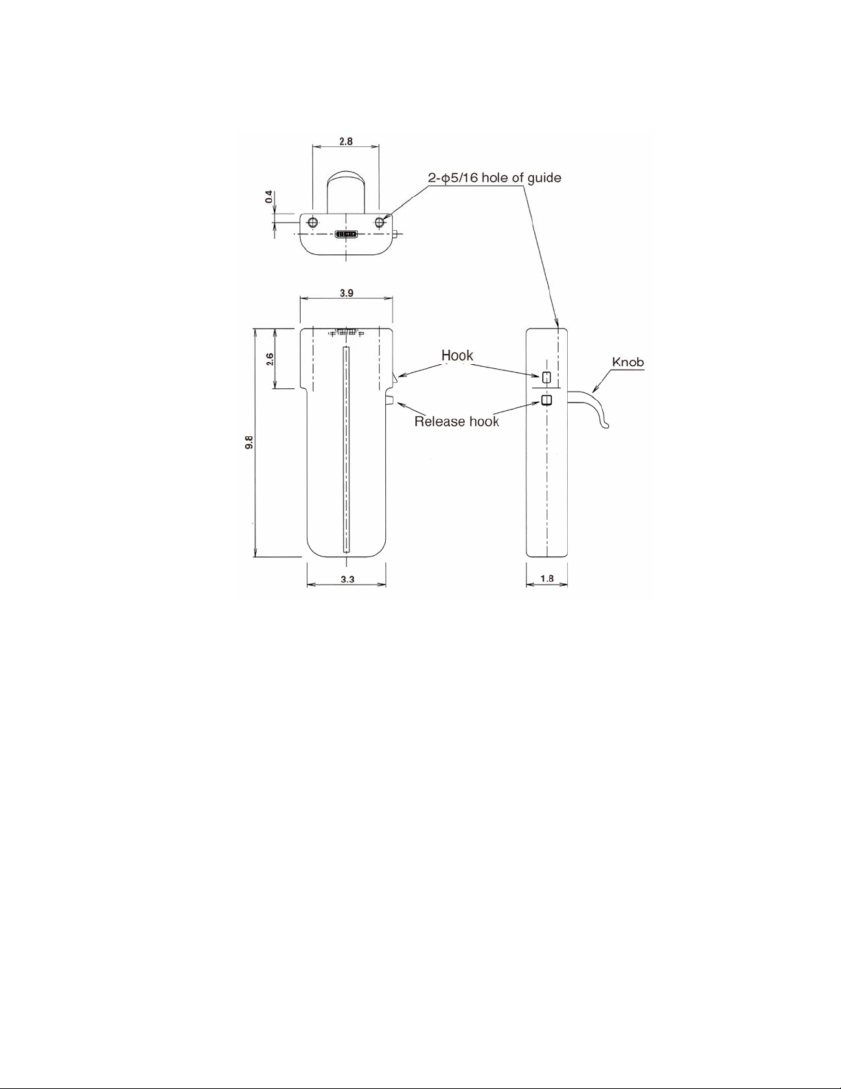
CCD sensor(Name and size)
Page 47
B02-T151 07
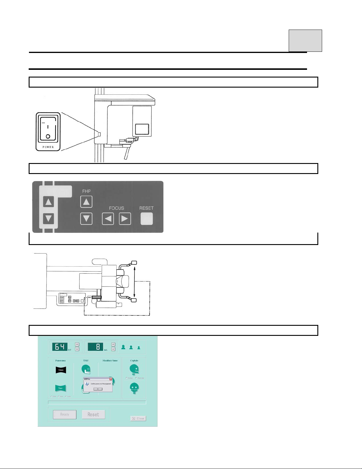
07.Explanation of each parts
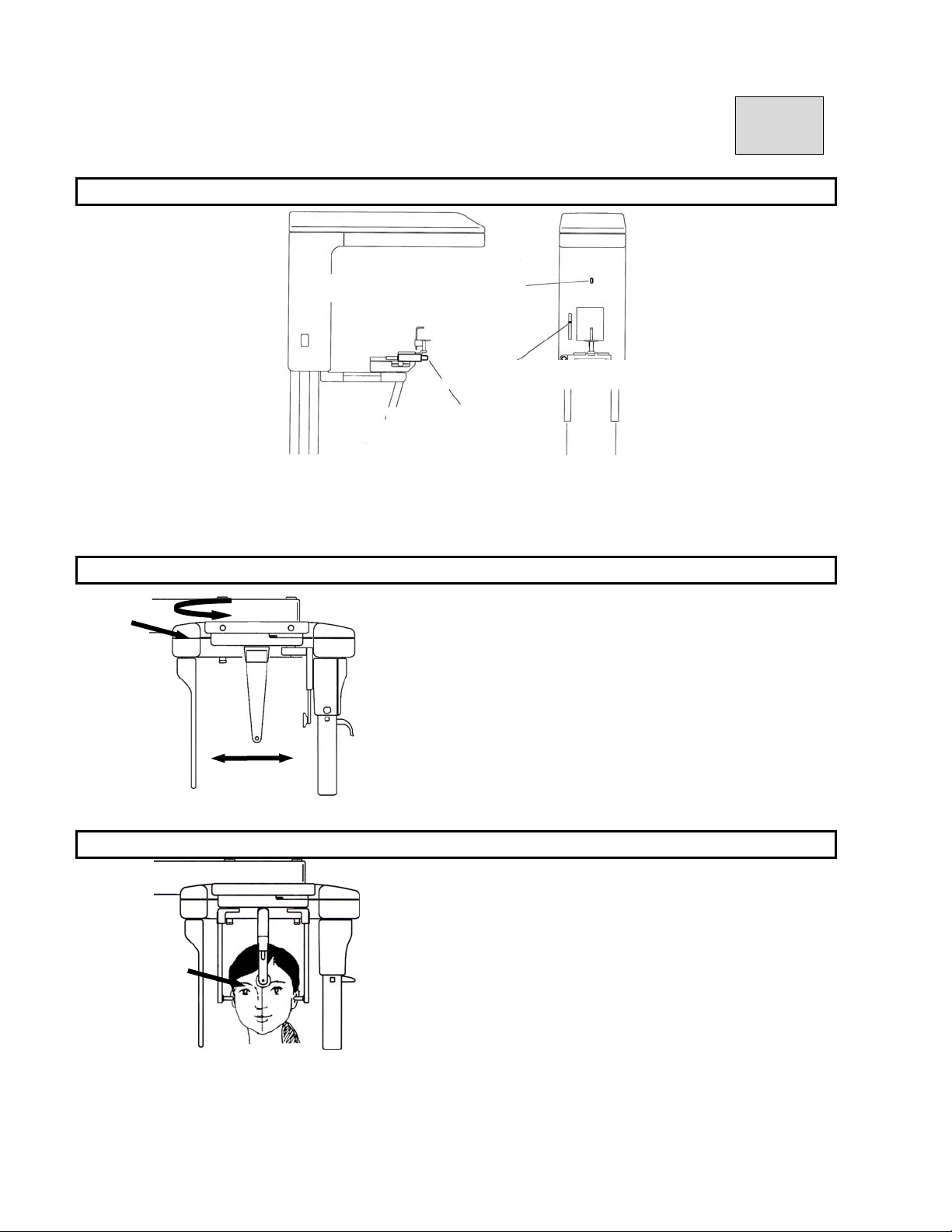
1.POWER SWITCH
*This switch is used to turn power ON/OFF.
To turn power ON:
Push “I“ on the power switch.
To turn power OFF:
Push “○” on the power switch.
2.Beam Line Operation Panel
*Use this to adjust positioning beam lines.
3.Knob to open and close the Head Holding Rod and Ear Rod (TMJ)
*Use this knob to hold / release Patient’s head.
4.Exposure Setting Screen
*Set the Exposure Mode, KvP and mA by using t his
screen.
Page 48
B02-T151 07
5.Names of Beam Line for the Patient Positioning
Median Plane Beam Line
Frankfort Plane Beam Line
Focus Beam Line
* Median Beam Line: Set this beam to the median line of a patient.
* Frankfort Beam Line: Set this beam to the Frankfort line of a patient.
* Focus Beam Line: Set this beam to the root of anterior teeth of upper and lower jaw of a patient.
6.Lever to open and close the Ear Rod
* Use this to hold / release Patient’s head
7.Nasion Holding Pad
* Put patient’s nasion to this pad.
Page 49
B02-T151 08
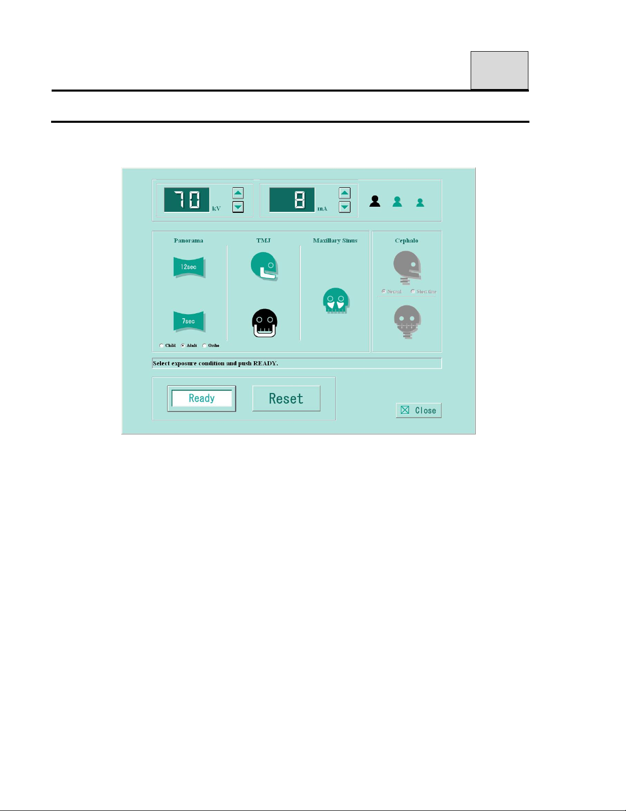
08.Exposure Setting Screen / Control Panel
You can access to this exposure setting screen via TWAIN driver.
Click either “Import” or “Scan” from diagnostic software / imaging software.
Operation Procedure section has detailed explanation of exposure settings.
Page 50
B02-T151 08
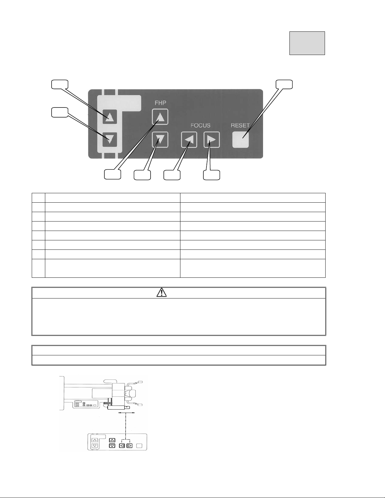
1 7
2
3
Name Function
No
1
Sliding Unit UP key Sliding Unit is elevated.
2
Sliding Unit DOWN key Sliding Unit is lowered.
3
Frankfort Beam Line UP key Frankfort Beam Line is elevated.
4
Frankfort Beam Line DOWN key Frankfort Beam Line is lowered.
5
Focus Beam Line Forward key Focus Beam Line is moved forward.
6
Focus Beam Line Backward key Focus Beam Line is moved backward.
7
RESET switch
4
65
The Rotation ARM and Cassette Holder are set
to the start position.
CAUTION
Speed of the up / down movement of Sliding Unit changes.
When the up / down key is depressed and held, the speed of first three seconds is slow, then
speed becomes fast.
To make a fine adjustment, press the key then immediately release a finger from the key
NOTE
Any of above keys won’t work under READY ON condition.
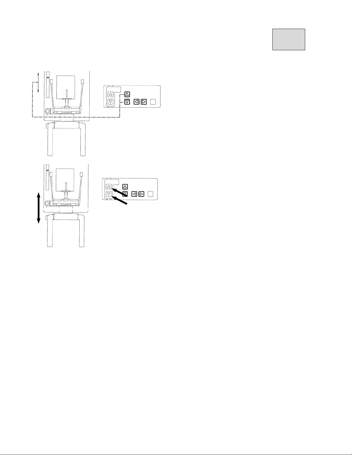
*Forward and backward movement of the Focus
Beam Line.
Page 51
B02-T151 08
*Up and down movement of the Frankfort Beam
Line.
*Up and down movement of the Sliding Unit.
Page 52
B02-T151 08
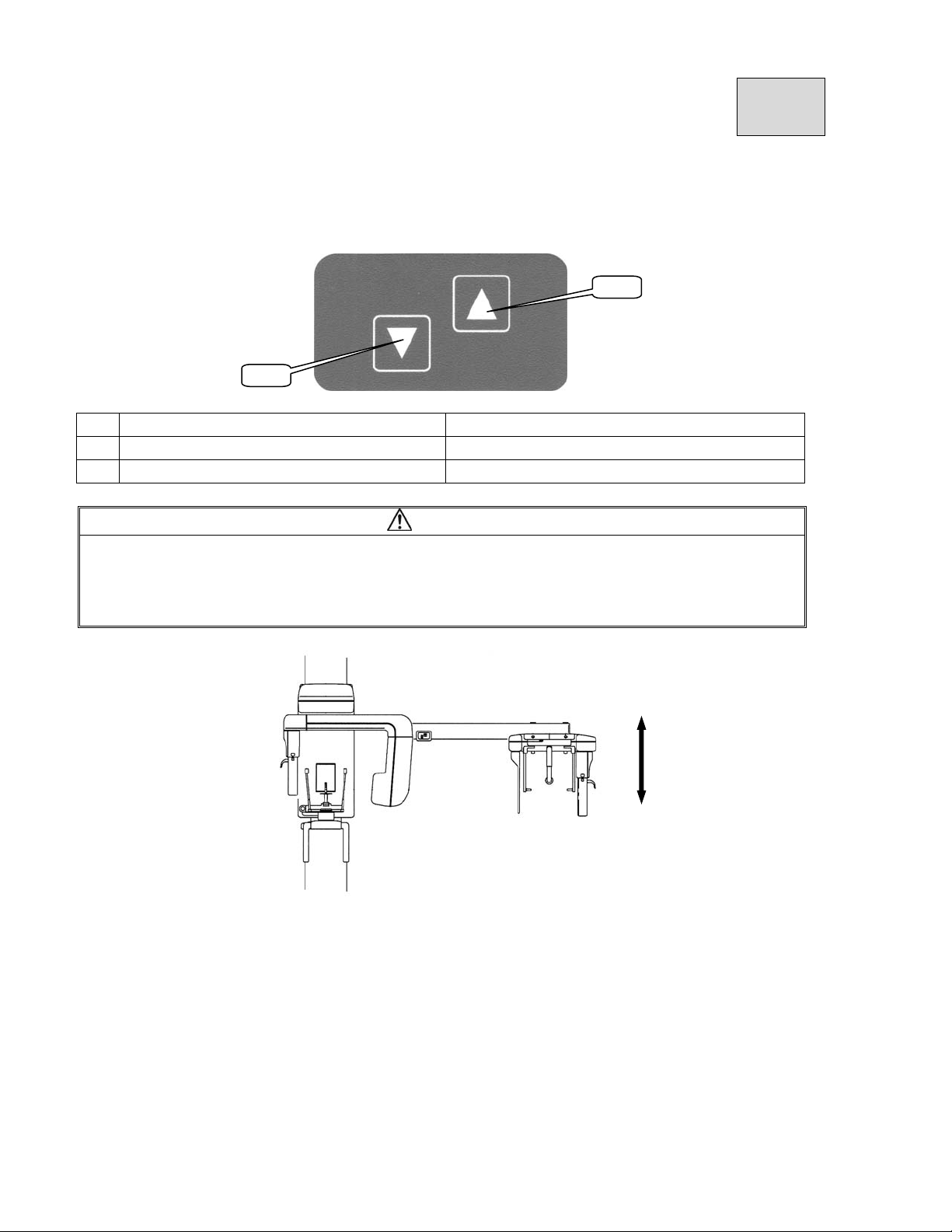
4.The Operation Panel for Cephalo ARM
1
2
No Name Function
1
Sliding Unit UP switch Sliding Unit is elevated.
2
Sliding Unit DOWN switch Sliding Unit is lowered.
CAUTION
Speed of the up / down movement of Sliding Unit changes.
When the up / down key is depressed and held, the speed of first three seconds is slow, then
speed becomes fast.
To make a fine adjustment, press the key then immediately release a finger from the key
Page 53
B02-T151 09
09.Preparation before exposure
1.Prepare accessories according to exposure mode
1.1.Panorama
1)A pair of Head Holding Rod (Panorama)
2)A Chinrest (Panorama)
3)A Bite Fork
4)A Cover for Bite Fork(a article of consumption)
1.2.Maxillary Sinus
1)A pair of Head Holding Rod (Panorama)
2)A Chinrest (Maxillary Sinus)
1.3.TMJ Lateral 4 sections
A pair of Ear Rod (TMJ Lateral 4 sections)
1.4.TMJ Front 2 sections
A pair of Ear Rod (TMJ Front 2 sections)
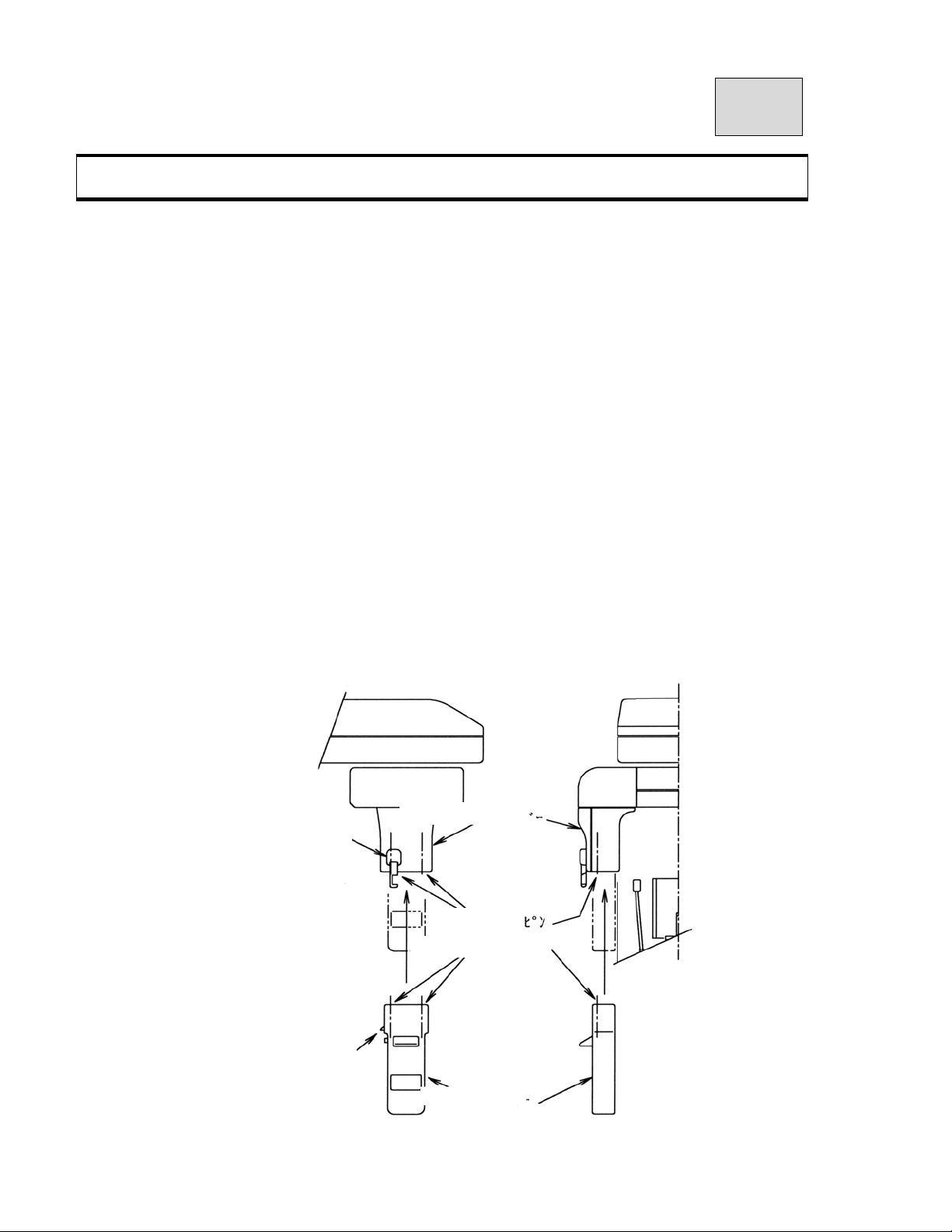
2.Attach digital CCD sensor
2.1.
①Attach CCD sensor
Set up CCD sensor
Hold CCD sensor by both hands and set up CCD sensor.
Secure CCD sensor by connecting sensor’s hook and fall prevention’s hook.
Radiography of Panorama・Maxillary sinus・TMJ lateral(tetramerous)・
TMJ front (bisection).
Fall prevention hook
CCD sensor hook
Holder of sensor
Guide pin
Hole of guide pin
CCD sensor
Page 54
B02-T151 09
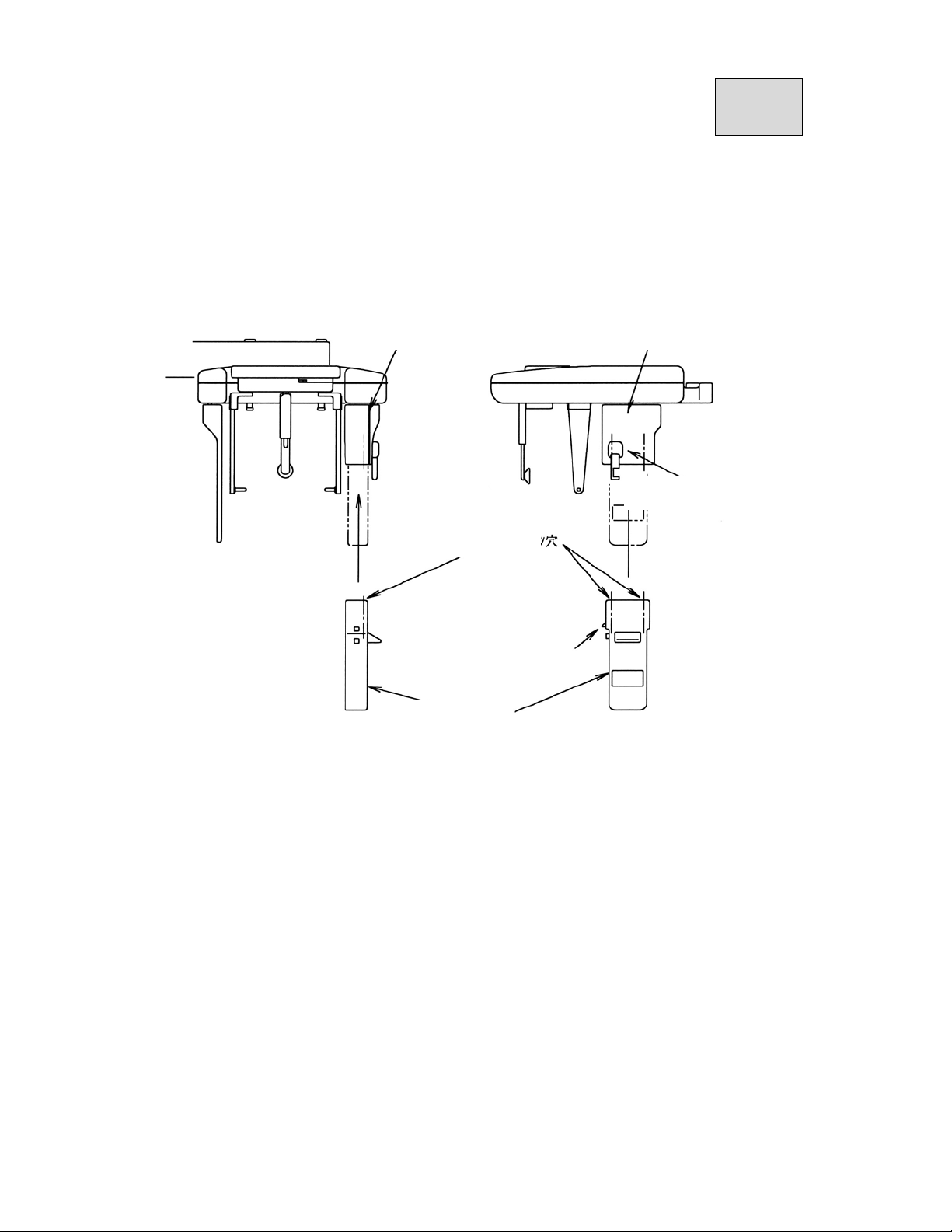
2.2.Cephalo Radiography
①Attach CCD sensor
Set up CCD sensor
Hold CCD sensor by both hands and set up CCD sensor.
Secure CCD sensor by connecting sensor’s hook and fall prevention’s hook.
Holder of sensor Holder of sensor
Hook of prevent dropout
Hole of guide pin
2.X-ray protector apron
Hook of CCD sensor
CCD sensor
Page 55
B02-T151 10
p
,
r
,
p
p
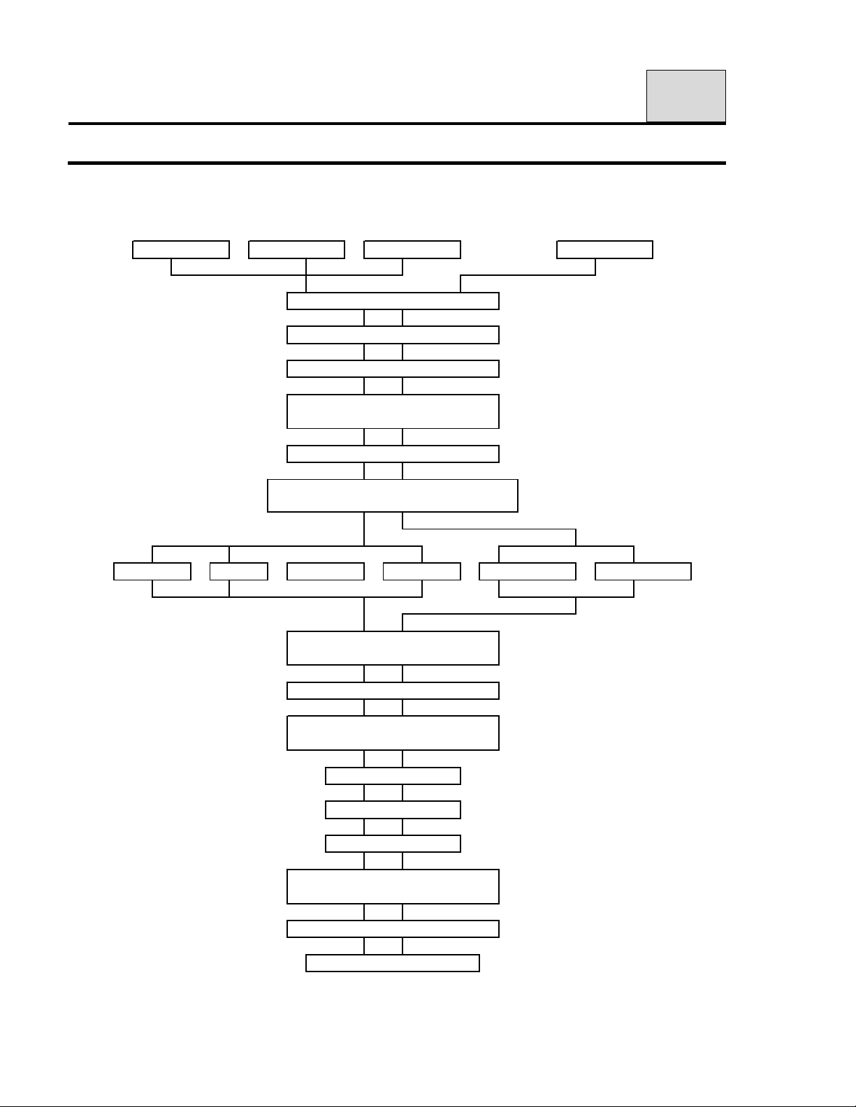
10.Flow Chart of Exposure Operation
Panorama
Panorama
MS TMJ
Prepare for exposure
Insert CCD senso
Turn ON PC for ADR PLUS
Start-up ADR PLUS
Refer to O
Turn ON power of equipment
Exposure display of ADR PLUS,
select ex
MS TMJ(LA)
Exposure display of ADR
input exposure condition
PLUS
eration Manual ADR
osure orbit
TMJ(PA)
Cephalo(LA)
Cephalo
Cephalo(PA)
Make patient positioning
Exposure display of ADR
Ready ON.
PLUS
Push X-ray switch
End of exposure
Release a patient
Display of ADR PLUS,
save ex
Confirm finish COOLING TIME
Power OFF(Equipment)
osure image
Page 56
B02-T151 11
11.Operation Procedure for Panorama
1. Learn Panoramic radiographic operation procedure that is basic X-ray radiograph.
2. Explanation of operation procedure in other modes that the same operation as
Panorama is omitted. Refer to operation procedure for Panorama according to
necessity.
1.Preparation for exposure
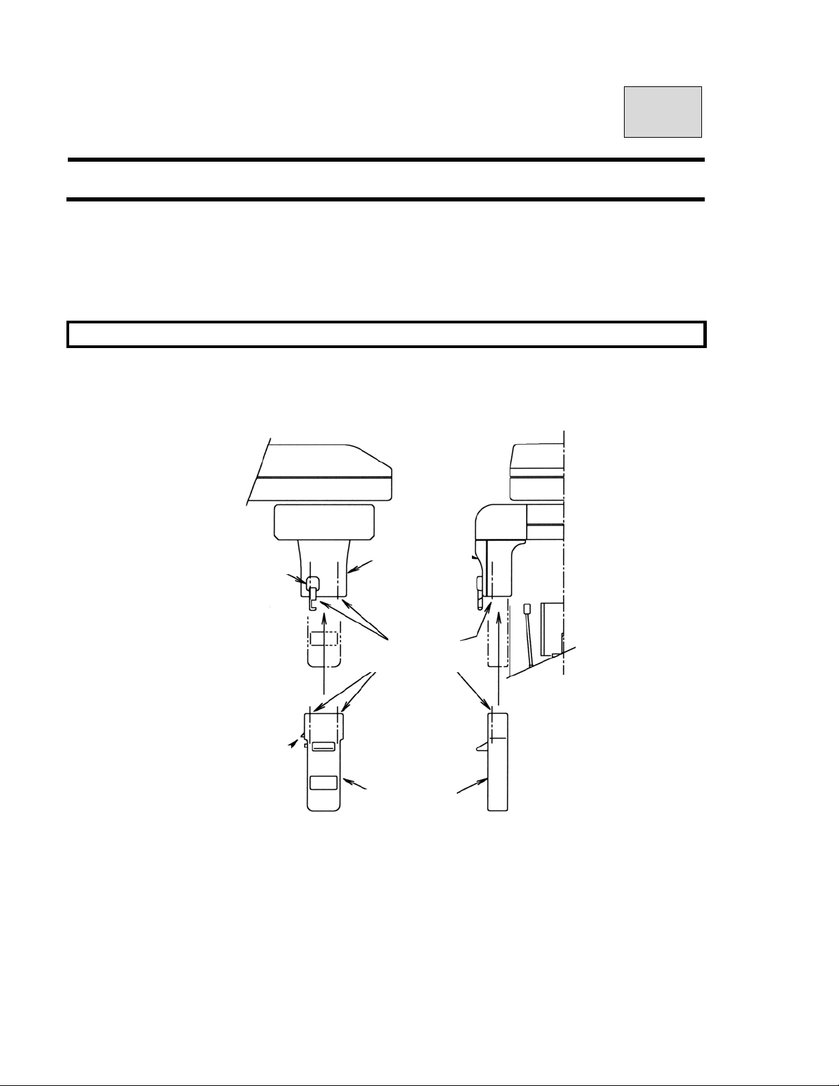
Set up CCD sensor
Hold CCD sensor by both hands and set up CCD sensor.
Secure CCD sensor by connecting sensor’s hook and fall prevention’s hook.
Fall prevention hook
CCD sensor hook
*X ray protective clothing
*Head holding for Panorama
*Chin rest for Panorama
*Bite fork
*Bite fork cover
Sensor holder
Guide pin
Hole of guide pin
CCD sensor
Page 57
B02-T151 11
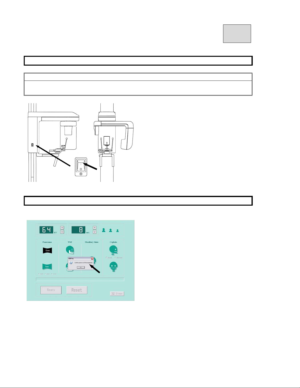
2.Turning power ON
NOTE
For safety, display of the indicator will be turned off with no switch operation if over 5 Minutes
passes after turning POWER switch ON.
① Push “I” on POWER switch.
3.Start Exposure Setting Screen
Click either “Import” or “Scan” from diagnostic
software / imaging software.
If the power of the equipment is ON,
click OK.
Page 58
B02-T151 11
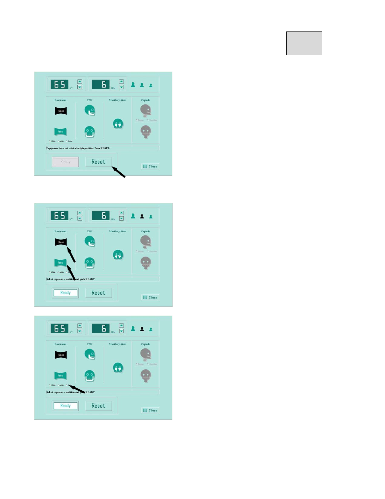
Set exposure conditions.
f you receive the message「Equipment is not at
the original position. Push the RESET button.」
Then click the「RESET button」.
Select an exposure mode
Click exposure speed “12sec” or “7sec.”
After selection, color of icon will be changed to black.
Click Child or adult or ortho (Ortho radial exposure).
*Ortho : Radiography of less tooth overlap.
Page 59
B02-T151 11
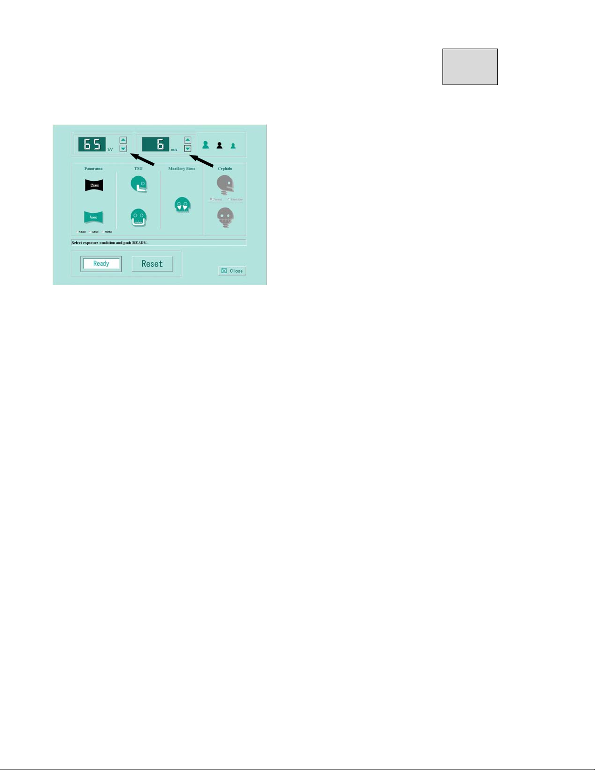
Setting kV(tube voltage)・mA(tube current)
Refer to article 17 for PANORAMA exposure condition and setting exposure condition.
Setting kV
Click kV ▲(UP)・or ▼(DOWN)to set kV.
Click mA ▲(UP)・or ▼(DOWN)to set mA.
Page 60
B02-T151 11
4. Patient Positioning
4. 1. Mounting of Chinrest and Insertion of Head Holding Rod (Panorama)
① Mount a Chinrest (Panorama) on the
Chinrest Unit.
② Insert a pair of Head Holding Rods
(Panorama).
Rotate the knob of Chinrest Unit to open Head
Holding Rods maximally.
④ Incrust a Bite Fork Cover on a Bite Fork,
and insert in a Chinrest (Panorama).
CAUTION
Be sure to change a Bite Fork Cover for every patient and dispose the used Bite Fork Cover.
4. 2. Put a X-ray protective apron on a patient and on an assistant.
4. 3. Guide a patient near to the equipment.
B02-T151 11
Page 61
* Depress either UP DOWN key on
Beam Control Panel or the one on the Sliding
Unit to move height of Chinrest (Panorama).
Depress up or down key to bring chinrest
height close to patient’s mandible.
4.4.Instruct a patient to stand toward the Pillar with foot under a Chinrest (Panorama).
4.5. Ask a patient to stand with his or her back and neck as straight as possible. Then hold grips.
4.6.Position patient
①Depress either UP・DOWN key on Beam
Control Panel, to move Chinrest (Panorama)
lightly touches patient’s mandible.
CAUTION
Pay enough attention to patient’s safety when Sliding Unit moves up and down.
②Instruct a patient to bite a groove of Bite Fork
with upper and lower anterior teeth. Instruct a
patient to put chin on a Chinrest.
*For an edentulous patient
Roll clean gauze on a Bite Fork, and instruct
patient to bite it.
③Adjust the beam height so that the beam hits
the patient’s miniscule of the ear (hole). Then
adjust the patient’s head as to beam indicates
Frankfort Plane (from miniscule of the ear to
bottom of the eye orbit)
Page 62
B02-T151 11
④ Lightly close the Head Holding Rods to
position patient’s head.
4.7.Turn Positioning Beams ON.
CAUTION
1. Laser Beams are used to position a patient.
2. Warn a patient not to look directly at the laser beam line.
3. Do not set the beam line to patient’s eyes.
NOTE
Positioning beams have AUTO POWER OFF function. Laser beam will be automatically turned off in 60
seconds after the beam is lit ON, or under READY ON condition.
In order to turn the laser on, depress “Forward Movement” key or “Backward Movement” key on FOCUS
Beam switch.
① Depress either Forward Movement ・ or
Backward Movement key of FOCUS switch on
the Beam Operation Panel to turn Patient
Positioning Beams on.
②”Median Beam Line”, “Focus Beam Line”,
and ”Frankfort Plane Beam Line” are equipped
Median Plane Beam Line
Frankfort Plane Beam
Focus Beam Line
Page 63
B02-T151 11
③Adjust the patient’s head so that the Median
Line Beam comes to the center of the patient’s
face,
④ Depress either UP・DOWN key of
Frankfort Beam on Beam Operation Panel
and align Frankfort Beam Line with Frankfort
Plane of a patient.
⑤ Carefully close Head Holding Rods to sup
port the patient’s head.
⑥ Depress either Forward Movement ・ or
Backward Movement key of FOCUS Beam
switch on Beam Operation Panel, and align
Focus Beam Line with roots of upper and
lower anterior teeth.
*When you align the Focus Beam Line, look a
patient from the side.
Page 64
B02-T151 11
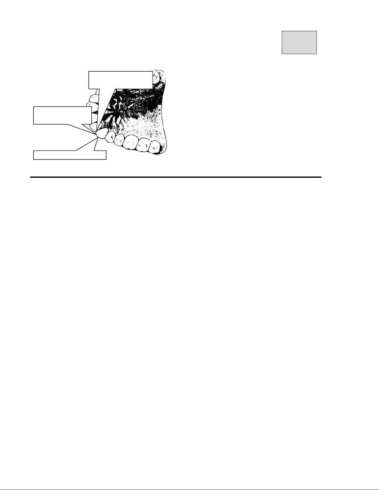
* Align the Focus Beam Line around Mesial
Mesial section of
canine teeth
Position to align
Focus Beam
Center of canine teeth
section of canine teeth
Page 65
B02-T151 11
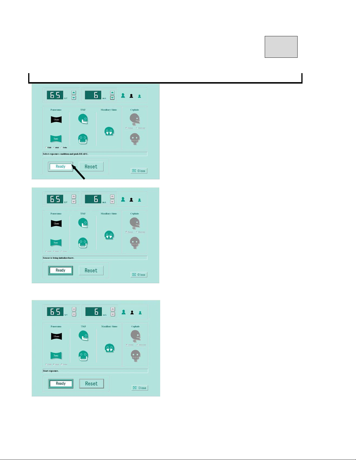
5.READY ON
①Click 「READY」
②Flash green「READY」icon,「initialization of
sensor」will be displayed and CCD sensor
will be initialed.
③After finish initialization of sensor,「READY」
icon will be changed to green, then「Start
exposure」will be displayed.
Page 66
B02-T151 11
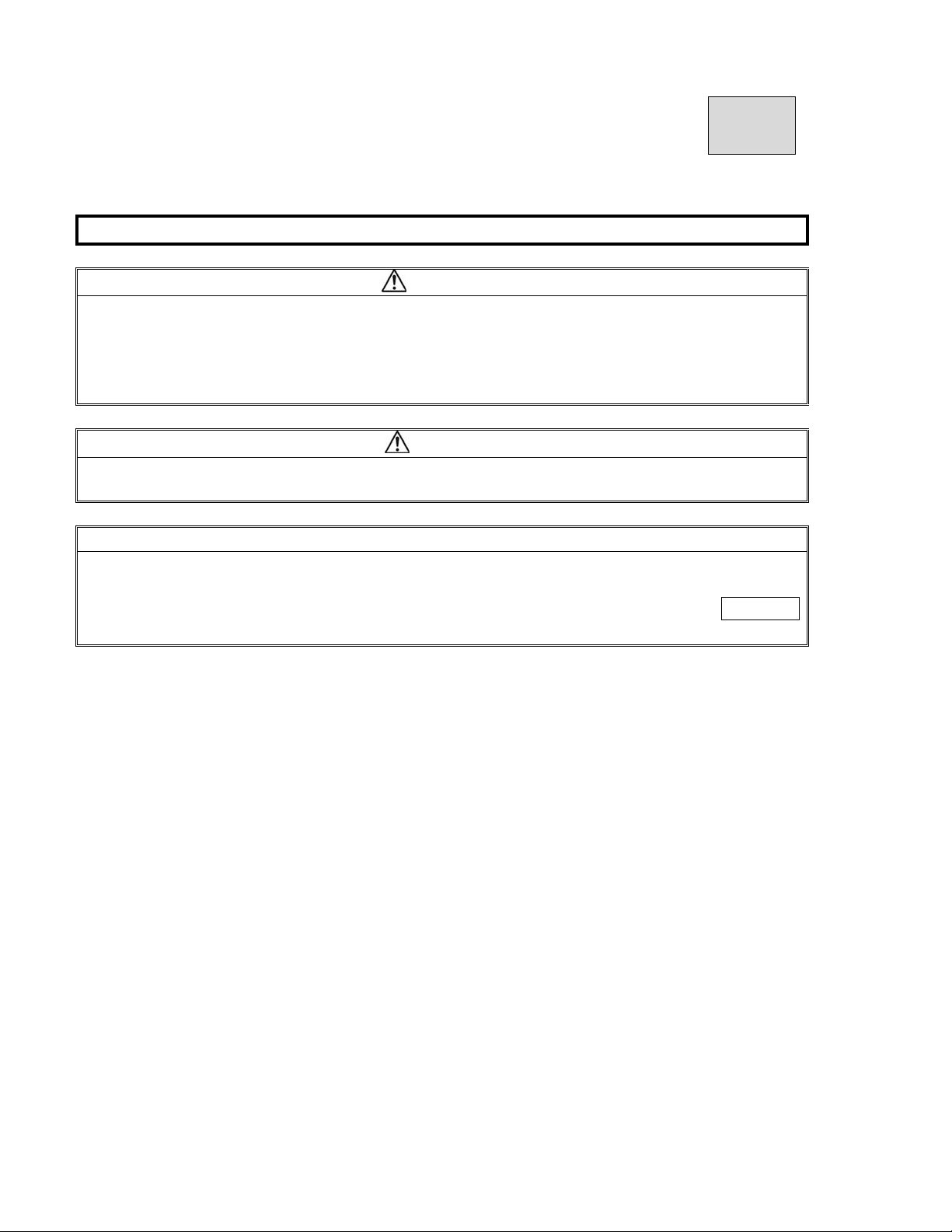
6.X-ray Exposure
WARNING
1.Other people except a patient and an operator should be outside of X-ray room.
2.The X-ray exposure switch should be depressed from outside of a X-ray room.
3.Carefully observe a patient while X-ray is irradiated, release an Exposure switch immediately
when any trouble happens.
4.Instruct a patient not to move while X-ray is irradiated.
CAUTION
The Rotation Unit starts to rotate and X-ray will be irradiated when an exposure switch is depressed.
Move away from the rotation area of the rotation unit.
NOTE
1.The exposure switch is deadman type. X-ray irradiation and the movement of the Rotation Unit will
stop as soon as the exposure switch is released.
2.If exposure switch is released while X-ray is irradiated, release a patient and depress RESET
key to bring Rotation Unit to the start position. Place a new X-ray film and take a radiograph again.
6.1.Exposure switch should be kept to push until end of exposure.
6.2.ARM Unit will start to rotate, “X-RAY ON” will be indicated on Indicator, and
X-ray irradiation will start with intermittent noise.
6.3.While X-ray is irradiated, indication of 「X-RAY ON」 blinks and buzzer keeps
to sound intermittently.
6.4.After end of radiograph, X-RAY indication will be lighted OFF, buzzer will stops to
sound, and ARM Unit will stop to rotate.
Page 67
B02-T151 11
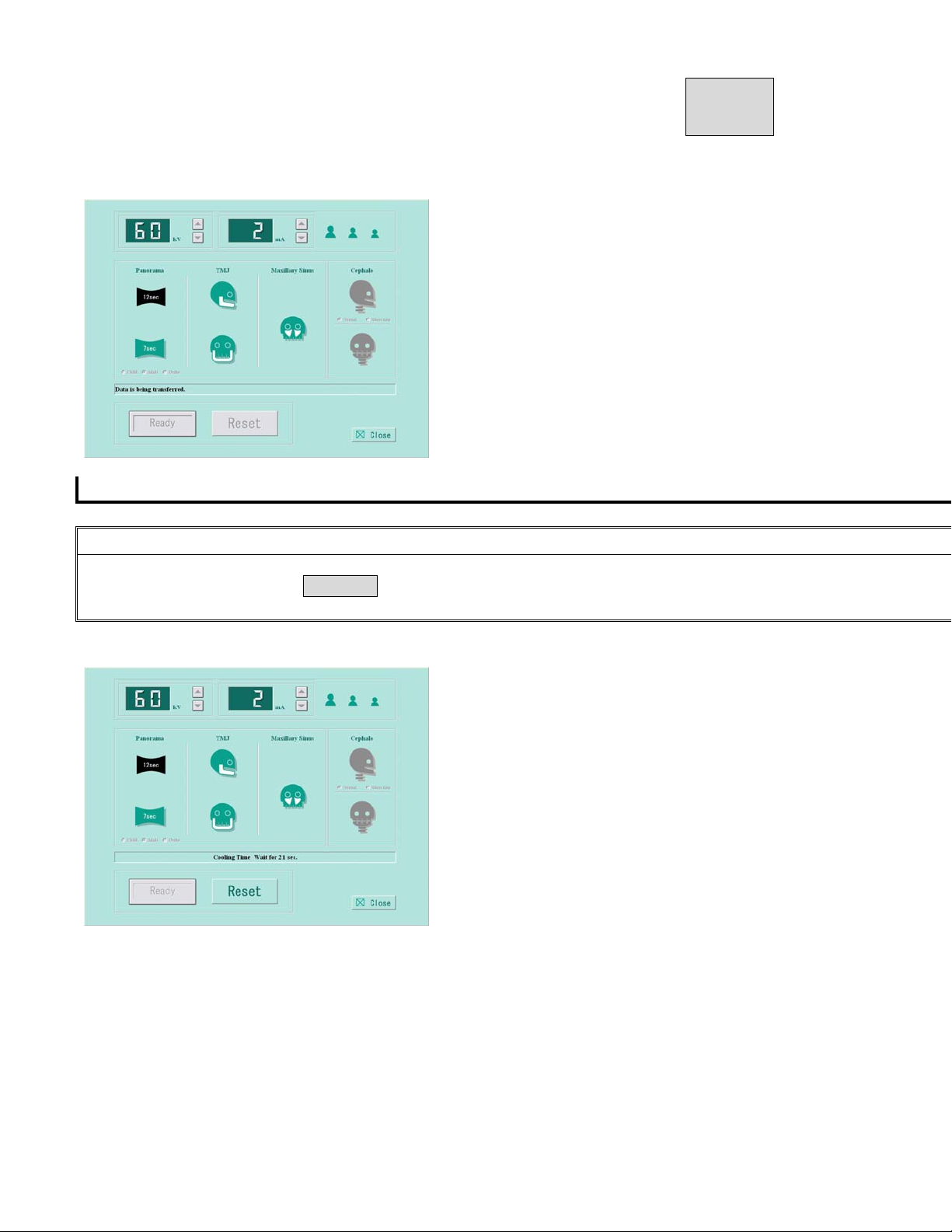
6.5.After exposure, data transfer on the display will be displayed.
7.COOLING TIME
NOTE
1.X-ray cannot be irradiated during COOLING TIME.
2.Any key operation excepting RESET key cannot be operated during COOLING TIME.
3.Do not turn power OFF until end of COOLING TIME.
After exposure, automatically cooling time will work.
Between cooling time, Cooling time」will be displayed.
After cooling time is elapsed, Cooling time」will be disappeared.
Page 68
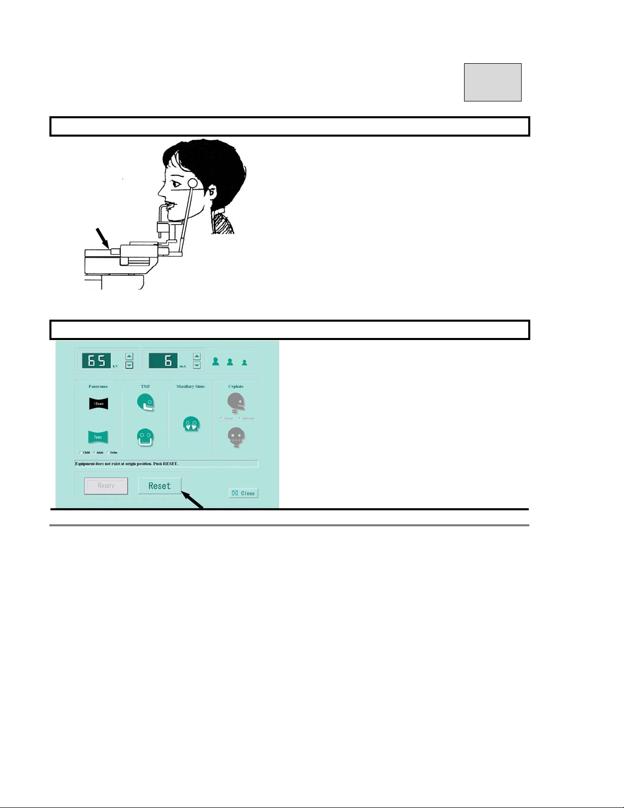
B02-T151 11
8.Release of a patient
* Carefully open Head Holding Rods and
release a patient.
9.Return the Rotation Unit to the Start Position
Click the「RESET button」.
Page 69
B02-T151 11
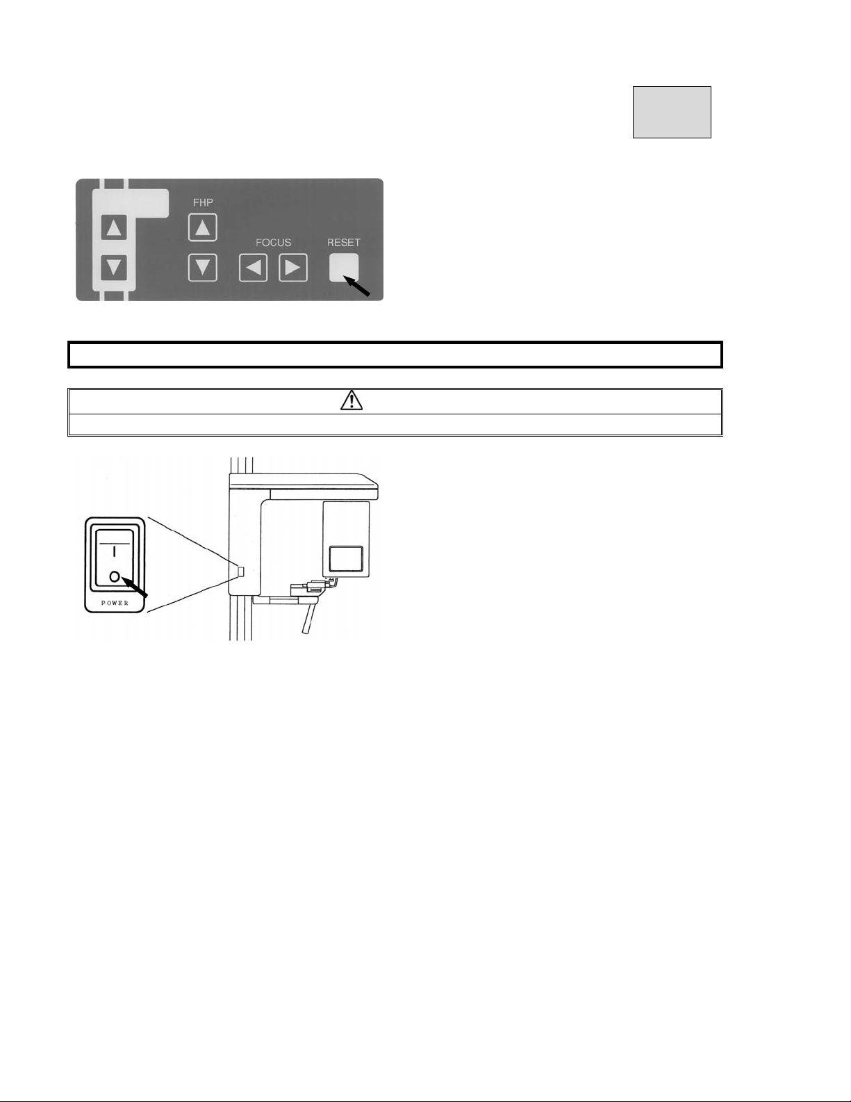
Or Hit Reset Key
10.Turning Power OFF
WARMING
To prevent the risk of accident, turn the power switch off when the unit is not in use.
* Depress “○” key on POWER switch.
Page 70
B02-T151 12
12.Operation Procedures for Maxillary Sinus
1. Learn the Panoramic radiographic operation procedures well. You can utilize Panoramic
operating procedures for other modes.
2. If procedures are the same as the one s of Panorama, explanations of op eration procedures
in other modes are omitted. If you have any questions, Refer to operation procedures for
Panorama.
1.Preparation for the Exposure
* X-ray Protective Apron
* Pair of Head Holding Rods (Panorama)
* Chinrest (Maxillary Sinus)
2.Turning Power ON
Refer to 11.3 Turning Power On in Operation procedure for Panoramic radiograph
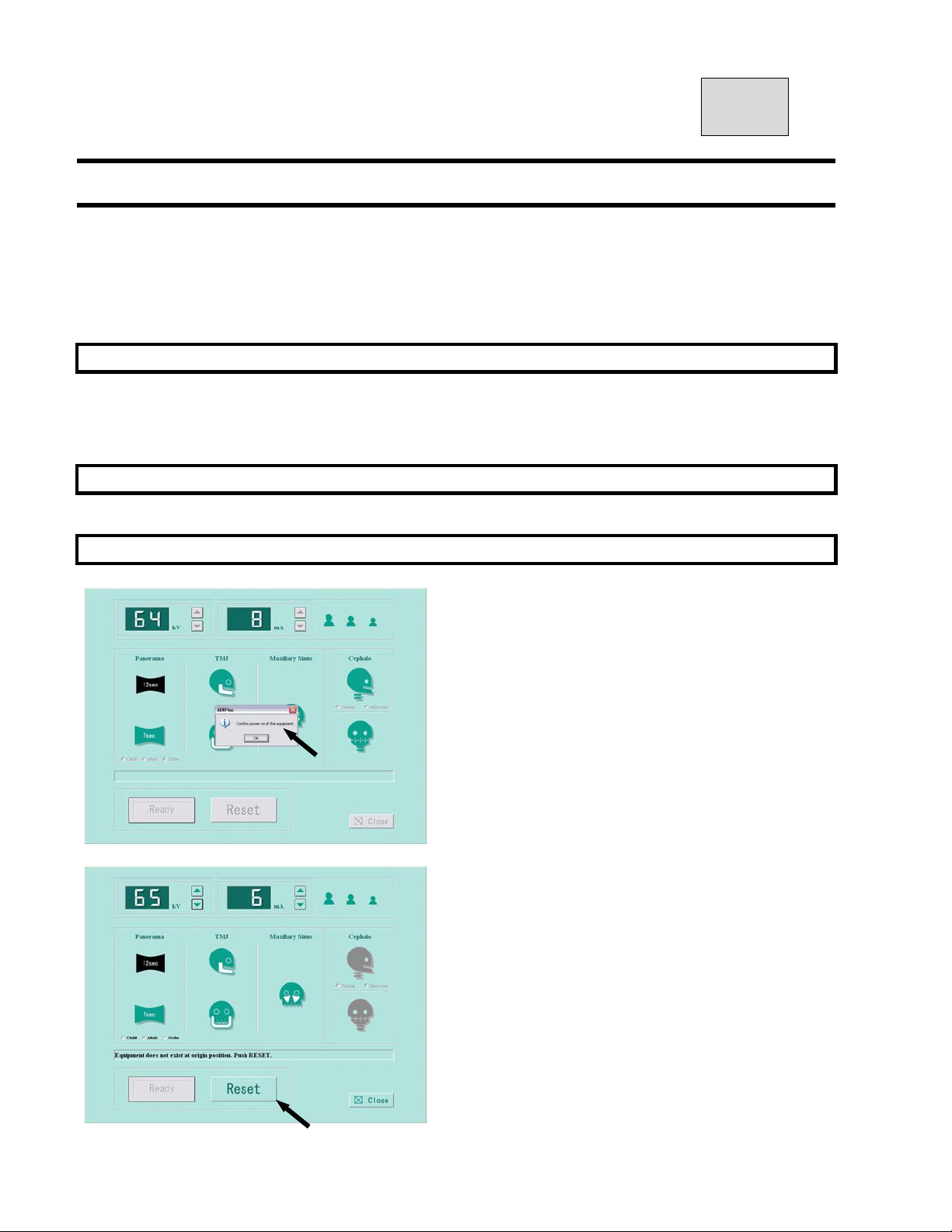
3.Start Exposure Setting Screen
Click either “Import” or “Scan” from diagnosticsoftw
are / imaging software.
If the power of the equipment is ON,
click OK.
Set exposure conditions.
If you receive the message「Equipment is not at
the original position. Push the RESET button.」
Then click the「RESET button」.
Page 71
B02-T151 12
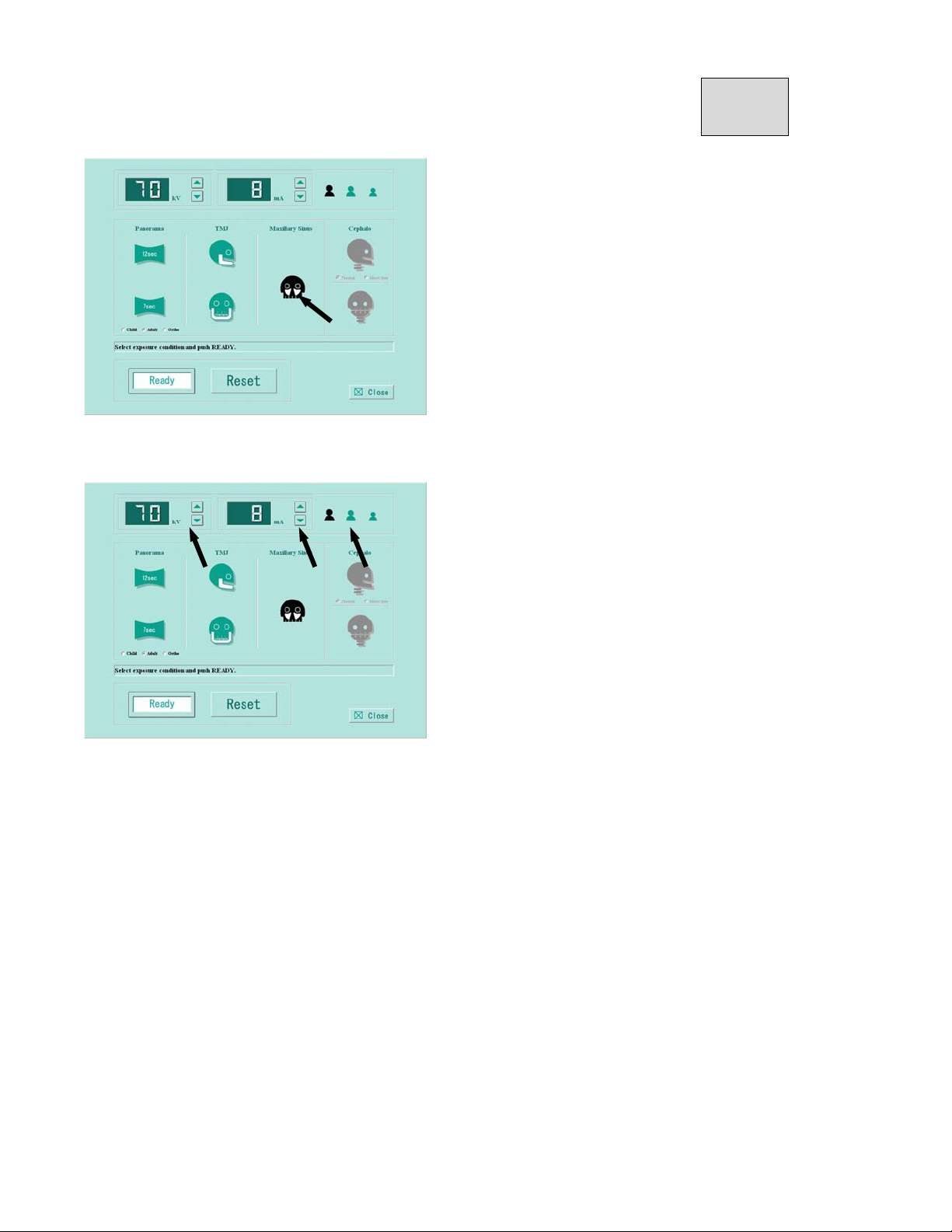
Setting the exposure mode
Click mark of maxillary sinus.
After select, mark will be changed to black.
Setting kV(tube voltage)・mA(tube current)
Refer to article 17 for PANORAMA exposure condition and setting exposure condition.
Setting kV
Click kV ▲(UP)・or ▼(DOWN)to set kV.
Click mA ▲(UP)・or ▼(DOWN)to set mA.
Page 72
B02-T151 12
4.Patient Positioning
NOTE
Patient positioning is the most important process to obtain the best radiographs.
4.1.Mounting of Chinrest and Insertion of Head Holding Rod (Maxillary Sinus)
③ Mount Chinrest (Maxillary Sinus) on the Chinrest
Unit.
④ Insert a pair of Head Holding Rods
(Maxillary Sinus)
③ Rotate the knob of Chinrest Unit to open Head
Holding Rods maximally.
4.2.Instruct a patient and an assistant to wear a X-ray protective apron.
4.3.Guide a patient near to the equipment.
* Depress either UP DOWN key on the
Beam Control Panel or the one on the Sliding Unit
to move height of Chinrest (Maxillary Sinus).
Depress up or down key to bring the chinrest
height close to patient’s mandible.
4.4.Instruct a patient to stand in the same position as Panoramic radiography.
4.5.Ask a patient to stand with his or her back and neck as straight as possible. Then hold grips.
Page 73
B02-T151 12
4.6.Position patient
① Depress either UP・DOWN key on Beam
Control Panel to move the Chinrest (Maxillary
Sinus) lightly touches patient’s mandible.
CAUTION
Pay enough attention to patient’s safety when the Sliding Unit moves up and down.
② Adjust the beam height so that the beam hits the
patient’s miniscule of the ear (hole). Then adjust
the patient’s head as to beam indicates Frankfort
Plane (from miniscule of the ear to bottom of the
eye orbit)
③Lightly close the Head Holding Rods to position
patient’s head.
4.7.Turn Positioning Beams ON.
CAUTION
1. Laser Beams are used to position a patient.
2. Warn a patient not to look directly at the laser beam line.
3. Do not set the beam line to patient’s eyes.
NOTE
Positioning beams have AUTO POWER OFF function. Laser beam will be automatically turned off in 60
seconds after the beam is lit ON, or under READY ON condition.
In order to turn the laser on, depress “Forward Movement” key or “Backward Movement” key on FOCUS Beam
switch.
Page 74
B02-T151 12
① Depress either Forward Movement ・ or
Backward Movement key of FOCUS switch on
the Beam Operation Panel to turn Patient
Positioning Beams on.
②”Median Beam Line”, “Focus Beam Line”,
and ”Frankfort Plane Beam Line” are equipped
Median Plane Beam Line
Frankfort Plane Beam Line
Focus Beam Line
③Adjust the patient’s head so that the Median Line
Beam comes to the center of the patient’s face,
④ Depress either UP・DOWN key of Frankfort
Beam on Beam Operation Panel and align
Frankfort Beam Line with Frankfort Plane of a
patient.
⑤ Carefully close the Head Holding Rods to supp
ort the patient’s head.
Page 75
B02-T151 12
⑥Depress either Forward Movement ・or Backward
Movement key of FOCUS Beam switch on the
Beam Operation Panel, and align Focus Beam
Line with roots of upper and lower anterior teeth.
5.READY ON
Please refer to 11.Operation Procedure for Panorama
6.X-ray Exposure
Refer to 11.Operation Procedure for Panorama
7.COOLING TIME
Refer to 11.Operation Procedure for Panorama
8.Release of a patient
Refer to 11.Operation Procedure for Panorama
9.Return Rotation Unit to Start Position
Refer to11.Operation Procedure for Panorama
10.Turning Power OFF
Refer to 11.Operation Procedure for Panorama
Page 76
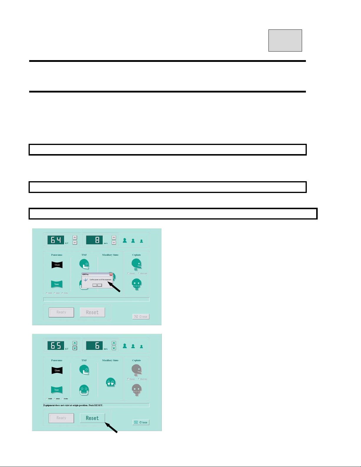
B02-T151 13
13.Operation Procedures for TMJ Lateral
(4 sections)
1. Learn the Panoramic radiographic operation procedures well. You can utilize Panoramic
operating procedures for other modes.
2. If procedures are the same as the ones of Panorama, explanations of operation
procedures in other modes are omi tted. If you have any questions, Refer to operation
procedures for Panorama.
1.Preparation for the Exposure
*X-ray Protective Apron
*Pair of Ear Rods (TMJ Lateral)
2.Turning Power ON
Refer to 11.3 Turning Power On in Operation procedure for Panoramic radiograph
3.Start Exposure Setting Screen
Click either “Import” or “Scan” from diagnosticsoftw
are / imaging software.
If the power of the equipment is ON,
click OK.
Set exposure conditions.
If you receive the message「Equipment is not at
the original position. Push the RESET button.」
Then click the「RESET button」.
Page 77
B02-T151 13
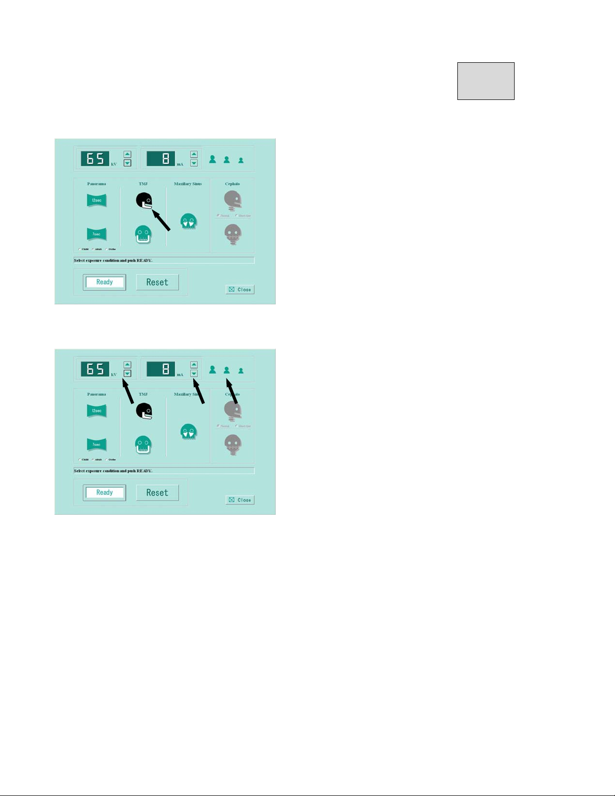
Setting the exposure mode
Click mark of mandibular joint lateral.
After select, mark will be changed to black.
Setting kV(tube voltage)・mA(tube current)
Refer to article 17 for PANORAMA exposure condition and setting exposure condition.
Setting kV
Click kV ▲(UP)・or ▼(DOWN)to set kV.
Setting mA
Click mA ▲(UP)・or ▼(DOWN)to set mA.
Page 78
B02-T151 13
4.Patient Positioning
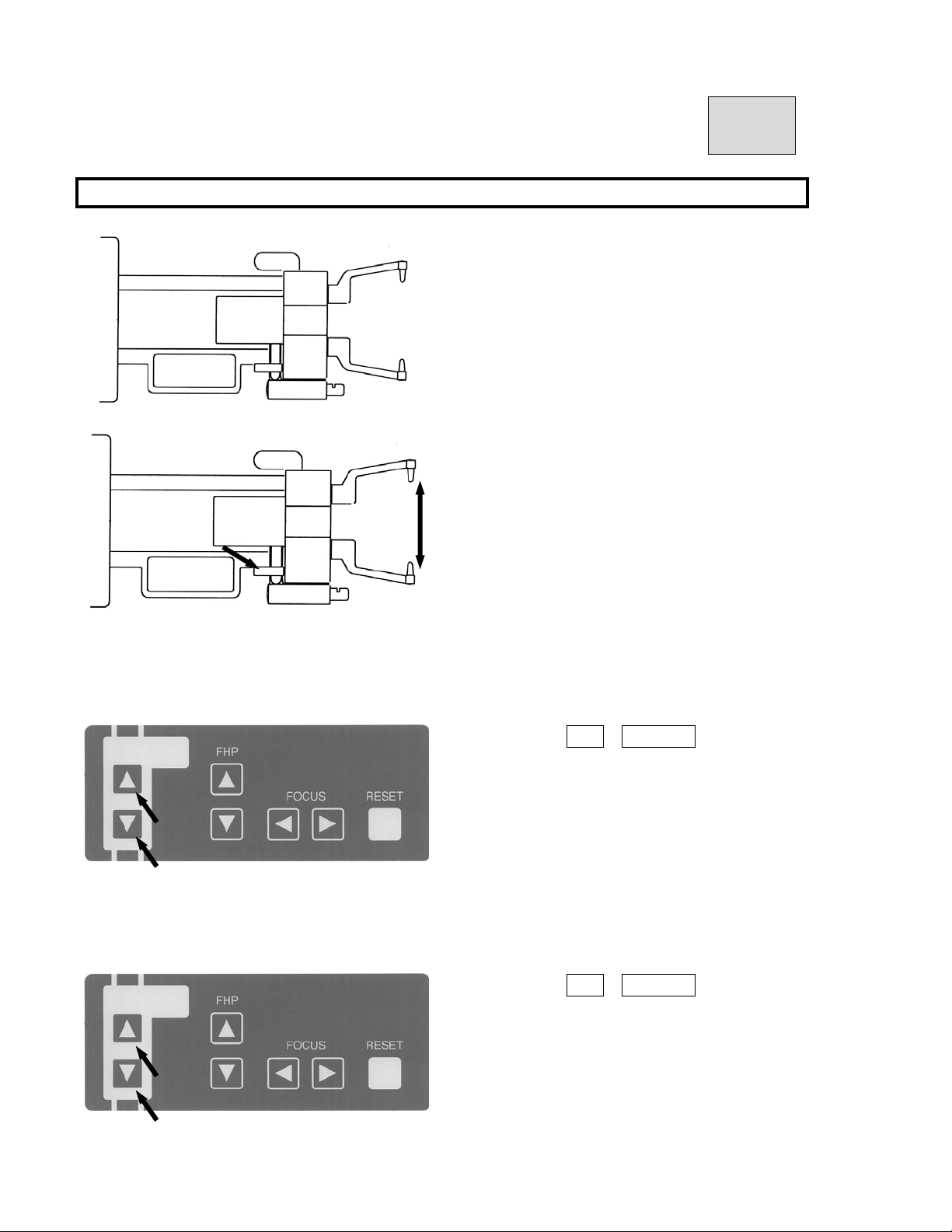
4.1.Mounting Ear Rods(TMJ Lateral)
① Mount Ear Rods (TMJ Lateral) on the Chinrest
Unit.
② Rotate the knob of the Chinrest Unit to open
Ear Rods (TMJ Lateral) maximally.
4.2.Instruct a patient and an assistant to wear X-ray protective apron.
4.3.Guide a patient near to the equipment.
Depress either UP DOWN key on the
Beam Control Panel or the one on the Sliding
Unit to move position of Ear Rods(TMJ Lateral).
Bring ear rods close to patient’s external auditory
foramen.
4.4.Instruct a patient to stand in the same position as Panoramic radiography.
4.5.Ask a patient to stand with his or her back and neck as straight as possible. Then hold grips.
Depress either UP DOWN key on the
Beam Control Panel or the one on the Sliding
Unit to move position of Ear Rods(TMJ Lateral).
Align ear rods to patient’s external auditory
foramen.
Page 79
B02-T151 13
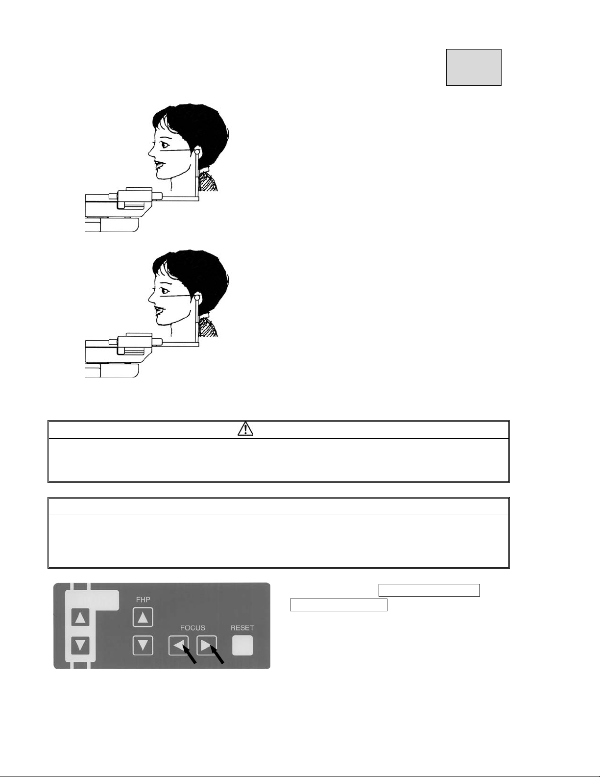
② Adjust the beam height so that the beam hits
the patient’s miniscule of the ear (hole). Then
adjust the patient’s head as to beam indicates
Frankfort Plane (from miniscule of the ear to
bottom of the eye orbit)
③ Rotate the knob of Chinrest ASSY to
insert Ear Rods (TMJ Lateral) into auricular
holes of a patient and fix Ear Rod lightly.
4.6.Turn Positioning Beams ON
CAUTION
1. Laser Beams are used to position a patient.
2. Warn a patient not to look directly at the laser beam line.
3. Do not set the beam line to patient’s eyes.
NOTE
Positioning beams have AUTO POWER OFF function. Laser beam will be automatically turned off in 60
seconds after the beam is lit ON, or under READY ON condition.
In order to turn the laser on, depress “Forward Movement” key or “Backward Movement” key on FOCUS
Beam switch.
① Depress either Forward Movement ・ or
Backward Movement key of FOCUS switch on
the Beam Operation Panel to turn Patient
Positioning Beams on.
Page 80
B02-T151 13
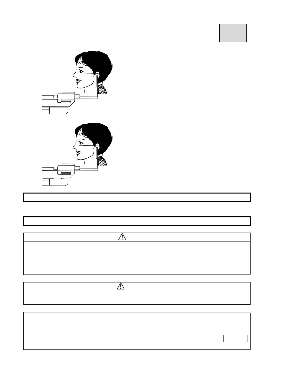
③Adjust the beam height so that the beam hits
the patient’s miniscule of the ear (hole). Then
adjust the patient’s head as to beam indicates
Frankfort Plane (from miniscule of the ear to
bottom of the eye orbit)
④ Rotate the knob of the Chinrest ASSY to
insert Ear Rods (TMJ Lateral) into auricular
holes of a patient and fix Ear Rod.
5.READY ON
Refer to 11.Operation Procedure for Panorama
6.X-ray Exposure
WARNING
1.Other people except a patient and an operator should be outside of X-ray room.
2.The X-ray exposure switch should be depressed from outside of a X-ray room.
3.Carefully observe a patient while X-ray is irradiated, release an Exposure switch immediately
when any trouble happens.
4.Instruct a patient not to move while X-ray is irradiated.
CAUTION
The Rotation Unit starts to rotate and X-ray will be irradiated when an exposure switch is depressed.
Move away from the rotation area of the rotation unit.
NOTE
1.The exposure switch is deadman type. X-ray irradiation and the movement of the Rotation Unit will
stop as soon as the exposure switch is released.
2.If exposure switch is released while X-ray is irradiated, release a patient and depress RESET
key to bring Rotation Unit to the start position. Place a new X-ray film and take a radiograph again.
Page 81
B02-T151 13
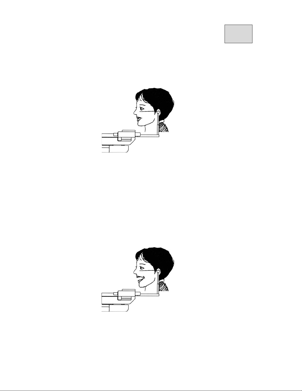
6.1.TMJ Lateral 4 sections consist of a series of two exposures. 1
nd
TMJ with mouth closed and 2
exposure for TMJ with mouse open.
st
exposure for the diagnosis of
6.2.Ask patient to close the mouth
6.3.Depress an exposure switch and hold until the end of exposure.
6.4.The Rotation Unit starts to rotate, X-RAY is indicated on indicator, and buzzer star ts to sound
intermittently.
6.5.While X-RAY is irradiated, 「X-RAY ON」 display blinks and an a udible warning will
sound.
6.6.After the end of first exposure, X-RAY indication display is turned OFF, an audi ble warning
stops, the Rotation Unit stops to rotate, then returns to the start position automatically.
6.7.Ask patient to open the mouth by lowering mandible
Page 82

B02-T151 13
6.8.Depress “READY” key to get into READY ON condition.
6.9.Depress an exposure switch and hold until the end of exposure.
6.10.ARM Unit starts to rotate, X-RAY will be indicated on indicator, and buzzer will
start to sound at the same time.
6.11.X-RAY keeps to be indicated and buzzer keeps to sound.
6.12.After 2nd exposure is finished, X-RAY will be lighted OFF, and buzzer will stop to
sound and ARM Unit will stop to rotate.
6.13.Refer to section 11.Operation procedure for Panorama and 8.X-ray exposure.
7.COOLING TIME
Refer to 11.Operation Procedure for Panorama
8.Release of a patient
Refer to 11.Operation Procedure for Panorama
9.Return Rotation Unit to Start Position
Refer to11.Operation Procedure for Panorama
10.Turning Power OFF
Refer to 11.Operation Procedure for Panorama
Page 83
B02-T151 14
14.Operation Procedures for TMJ Frontal
(2 sections)
1. Learn the Panoramic radiographic operation procedures well. You can utilize Panoramic
operating procedures for other modes.
2. If procedures are the same as the ones of Panorama, explanations of operation
procedures in other modes are omitted. If you have an y questions, Refer to operation
procedures for Panorama.
1.Preparation for the Exposure
*X-ray Protective Apron
*Pair of Ear Rods (TMJ Front)
2.Turning Power ON
Refer to 11.Operation Procedure for Panorama 3.Turning Power ON
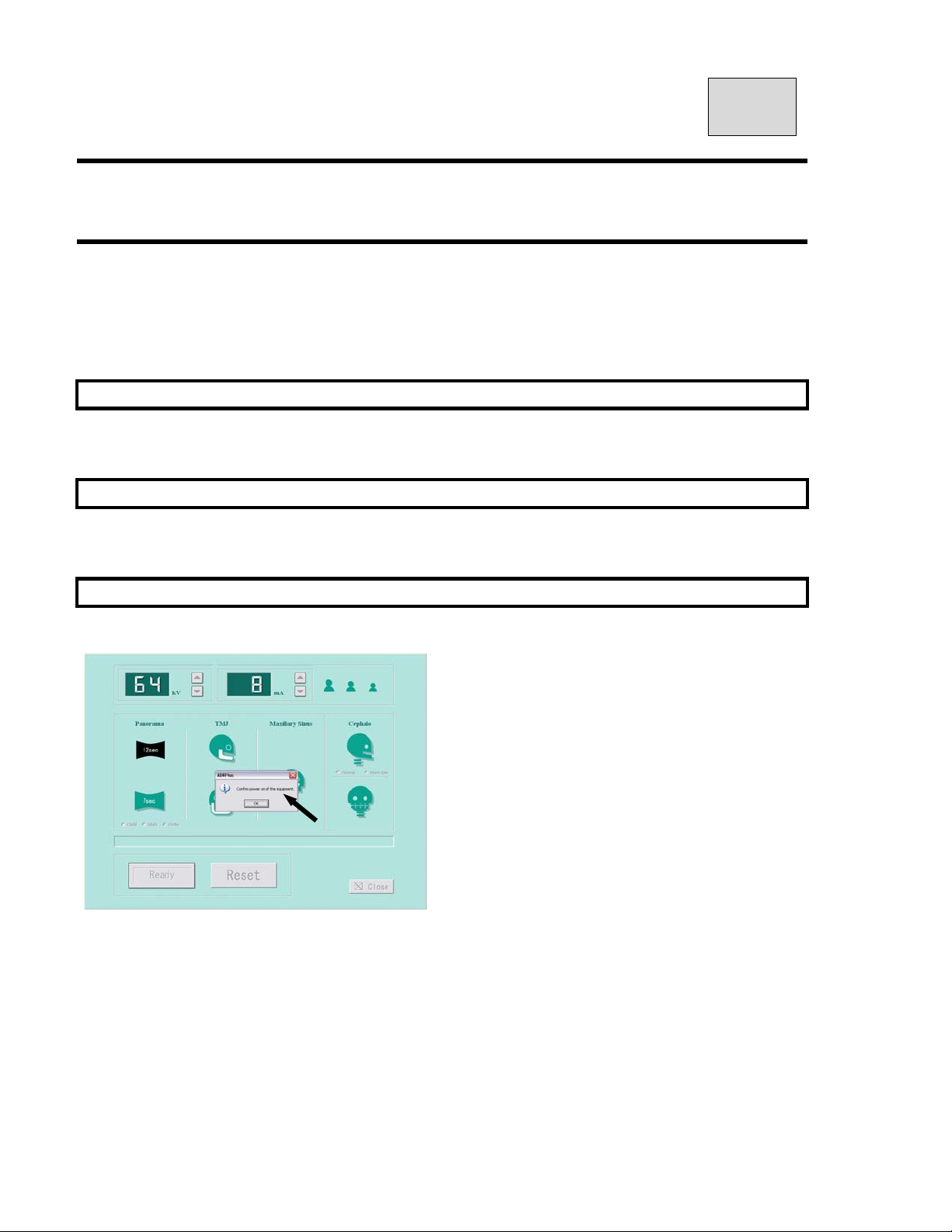
3.Start Exposure Setting Screen
Click either “Import” or “Scan” from diagnostics
oftware / imaging software.
If the power of the equipment is ON,
click OK.
Page 84
B02-T151 14
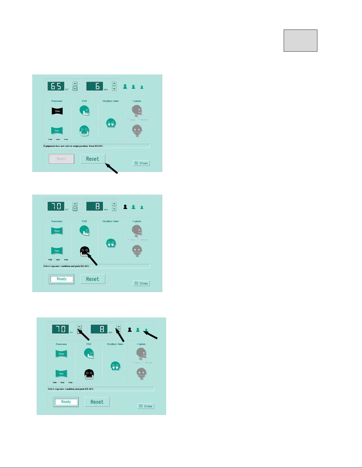
Set exposure conditions.
If you receive the message「Equipment is not at
the original position. Push the RESET button.」
Then click the「RESET button」.
Setting the exposure mode
Click icon of mandibular joint front.
After select, icon will be changed to black.
Setting kV(tube voltage)・mA(tube current)
Refer to article 17 for PANORAMA exposure condition and setting exposure condition.
Setting kV
Click kV ▲(UP)・or ▼(DOWN)to set kV.
Setting mA
Click mA ▲(UP)・or ▼(DOWN)to set mA.
Page 85
B02-T151 14
4.Patient Positioning
4.1.Mounting Ear Rods (TMJ Front)
①Mount “Ear Rods (TMJ Frontal) on the Chinre st
Unit.
②Rotate the knob of the Chinrest Unit to open Ear Rods (TMJ
Front) maximally.
4.1.Instruct a patient and an assistant to wear X-ray protective apron.
4.2.Guide a patient near to the equipment.
Depress either UP DOWN key on the Beam Control
Panel or the one on the Sliding Unit to move position of Ear
Rods (TMJ Lateral).
Bring ear rods close to patient’s external auditory foramen.
4.3.Instruct a patient to stand in the same position as Panoramic radiography
4.4.Ask a patient to stand with his or her back and neck as straight as possible. Then hold grips.
Depress either UP DOWN key on the Beam Control
Panel or the one on the Sliding Unit to move position of Ear
Rod(TMJ Frontal).
Align ear rods to patient’s external auditory
foramen.
B02-T151 14
Page 86
4.5.Turn Positioning Beams ON
② Horizontally align to the patient’s naso-auricularplane.
③Rotate the knob of the Chinrest ASSY to insert Ear Rod (TMJ
Frontal) into auricular holes of a patient and fix Ear Rod
lightly.
CAUTION
1. Laser Beams are used to position a patient.
2. Warn a patient not to look directly at the laser beam line.
3. Do not set the beam line to patient’s eyes.
NOTE
Positioning beams have AUTO POWER OFF function. Laser beam will be automatically turned off in 60 seconds after the
beam is lit ON, or under READY ON condition.
In order to turn the laser on, depress “Forward Movement” key or “Backward Movement” key on FOCUS Beam switch.
Depress either Forward Movement・or Backward Movement
key of FOCUS switch on the Beam Operation Panel to turn
Patient Positioning Beams on.
B02-T151 14
Page 87
③ Adjust beam height so that Frankfort beam hits the
naso-auricular plane
④Rotate the knob of the Chinrest ASSY to insert Ear Rods (TMJ
Lateral) into auricular holes of a patient and fix Ear Rod.
5.READY ON
Refer to 11.Operation Procedure for Panorama 7.READY ON.
6.X-ray Exposure
WARNING
1.Other people except a patient and an operator should be outside of X-ray room.
2.The X-ray exposure switch should be depressed from outside of a X-ray room.
3.Carefully observe a patient while X-ray is irradiated, release an Exposure switch immediately
when any trouble happens.
4.Instruct a patient not to move while X-ray is irradiated.
CAUTION
The Rotation Unit starts to rotate and X-ray will be irradiated when an exposure switch is depressed.
Move away from the rotation area of the rotation unit.
NOTE
1.The exposure switch is deadman type. X-ray irradiation and the movement of the Rotation Unit will stop as soon as the
exposure switch is released.
2.If exposure switch is released while X-ray is irradiated, release a patient and depress RESET key to bring
Rotation Unit to the start position. Place a new X-ray film and take a radiograph again.
B02-T151 14
6.1.Depress an exposure switch and hold until the end of exposure.
Page 88

6.2.The Rotation Unit starts to rotate, X-RAY is indicated on indicator, and buzzer starts to sound intermittently.
6.3.While X-RAY is irradiated, 「X-RAY ON」 display blinks and an audible warning will sound
6.4.After the end of the exposure, X-RAY indication displa y is turned OFF, an audible warning stops, and the
Rotation Unit stops to rotate.
7.COOLING TIME
Refer to 11.Procedure of Panorama Exposure Operation
8.Release of a Patient
Refer to 11.Procedure of Panorama Exposure Operation
9.Return Rotation Unit to Start Position
Refer to 11.Procedure of Panorama Exposure Operation
10.Turning Power OFF
Refer to 11.Procedure of Panorama Exposure Operation
 Loading...