

Page 1
B02-T216E-A Bel-Cypher Pro
Operation Manual
Digital Panoramic Radiograph
Bel-Cypher Pro
Notice to the operator and maintenance supervisor
*Read this instruction manual before operation. After reading this manual,
keep it in a safe place near the X-ray machine for the easy access.
Caution: Federal law restricts this device to sale by or
on the order of a physician, dentist or other licensed
practitioner
The classification is indicated as follows
According to the type of protection against electric shock. : Class Ⅰ
According to the degree of protection against electric shock. : Type B applied part
TAKARA BELMONT CORPORATION.
Page 2
B02-T216E-A Bel-Cypher Pro
Thank
you very much
for purchasing
our equipment
Model
Bel-Cypher Pro
.
Please read this operation manual carefully before operation in order to use the X-Ray
machine properly and safely.
INDICATION FOR USE: The Bel-Cypher Pro dental panoramic X-ray system is indicated
for use as generator of radiographic images of the dento-maxilofacial region and is
intended for dental examination and diagnosis of diseases of the tooth, jaw, and oral
structures.
CAUTION
If you run software that force heavy load to PC, transfer & acquisition of image could be interrupted.
Page 3

B02-T216E-A Bel-Cypher Pro
CONTENTS
1. Introduction
2. Warning
3. Explanation of Equipment
4. Specifications
5. Standard Accessories
6. Names of the Major Components
7. Explanation of each part
8. Operation Panel
9. Preparations before Exposure
10. Flow Chart of Exposure
11. Operation Procedure for Panorama & Panoramic Bitewing
12. Operation Procedure for TMJ
13. Table of Exposure Settings
14. Magnification of Image
15. Dose information
16. Daily Maintenance
17. Trouble Shooting
18. X-ray Tube Focus, Sensor Location, Collimator & Exposure Field
19. Physical Dimensions
20. Labels
21. Technical Data
01 1 / 2
02 1 /11
03 1 / 1
04 1 / 2
05 1 / 1
06 1 / 1
07 1 / 3
08 1 / 1
09 1 / 1
10 1 / 1
11 1 / 24
12 1 / 10
13 1 / 1
14 1 / 1
15 1 / 2
16 1 / 1
17 1 / 1
18 1 / 3
19 1 / 1
20 1 / 3
21 1 / 9
Page 4

B02-T216E-A Bel-Cypher Pro
22.Maintenance
23.Contact Information
24.Revision Record of this manual
22 1 / 2
23 1 / 1
24 1 / 1
Page 5

B02-T216E-A Bel-Cypher Pro
01
01.Introduction
1.Read this manual carefully before using this equipment for the first time.
2.Be sure to observe warnings and prohibited items when operating the equipment.
3.Read the operation manual from beginning to end.
Reading the operation manual from halfway through might lead to misunderstanding.
4.If you have any issues, read this manual again to confirm the portion in question.
5.The operation procedure of a Panoramic radiograph is the basis of X-ray radiography.
Your can use this procedure for other radiography such as TMJ.
6.Explanation of the operation procedure of other radiograph are omitted, if the procedures are same
as the one of Panoramic radiograph.
Refer to operation procedure of panoramic radiograph, if you have any questions about operating
procedures.
7.Discharge
Be sure to observe the contents of this operation manual.
Even if any trouble or an accident happens due to wrong use, we are not responsible for them.
8.Warranty Period
Warranty period is two years after purchase of the equipment.
We will repair failures or defects under this warranty. This warranty is void when a failure or defect
is caused by conditions beyond the manufacturer’s control, such as damage resulting from
mishandling, neglect, misuse, improper maintenance, accident or alteration or repair by anyone
other than Belmont or an authorized Belmont dealer. See your warranty card for more information.
9.Maintenance
Be sure to properly maintain your equipment.
The responsibility to maintain medical equipment lies with the user.
10.Period for repair and parts supply
We will continue to supply parts for the equipment for up to 10 years after it has been
discontinued.
11.
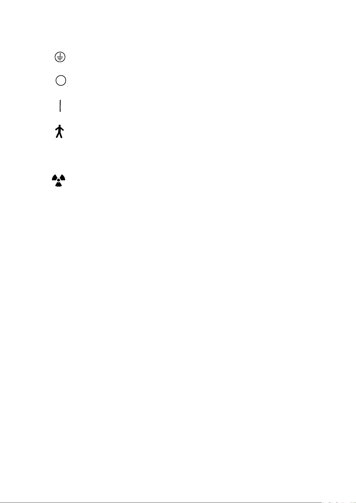
means “ Attention, consult accompanying documents ”.
01-1
Page 6
B02-T216E-A Bel-Cypher Pro
12. means “ Protective earth(ground) “.
13. means “ OFF (Power: disconnection from the mains) “.
14.
means “ ON (Power: connection to the mains) “.
15. means “Type B“ Applied part
16.
means “Class 1 Laser product”.
17. means ionizing radiation.
18.No user serviceable items inside.
19.Conformability to indicated X-RAY requirement was determined in accordance with R10
sequences that follow ISO497.
20.The use of ACCESSORY equipment not complying with the equipment safety requirements of this
equipment may lead to a reduced level of safety of the resulting system. Consideration relating
to the choice shall include:
Use of the accessory in the PATIENT VICINITY
Evidence that the safety certification of the ACCESSORY has been performed in accordance
to the appropriate IEC 60601-1 harmonized national standard.
Computer and monitor shall comply with IEC60950-1 or IEC60601-1
21.Original manual was created in Japanese.
22.In addition to this operation manual, we supply an Installation manual
01-2
Page 7
B02-T216E-A Bel-Cypher Pro
an
ous situation, which, if not avoided, may result in death, serious injury and/or property
could result in death, serious injury
may result in minor or moderate
when the instructions are not
02
02.Warning
WARNING
Always conform to the safety work standards.
Repair work for internal parts of the equipment involves high risk. This should be strictly conducted by
authorized service personnel only.
NOTE
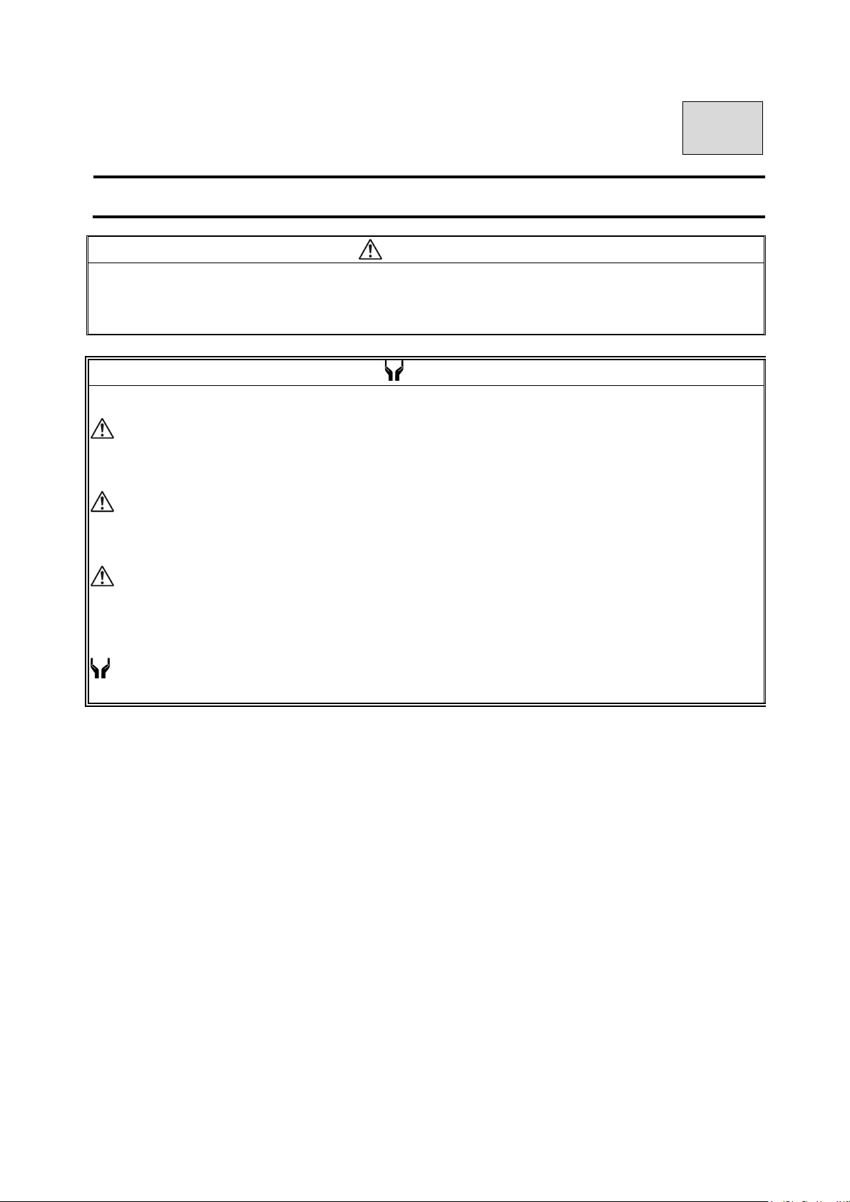
The warning messages in the Operation Manual are defined and classified as follows:
DANGER
Indicates an imminently hazard
damage such as total loss of equipment and fire when the instructions are not followed.
WARNING
Indicates a potentially hazardous situation, which, if not avoided,
and/or property damage such as total loss of equipment and fire when the instructions are not followed.
CAUTION
Indicates a potentially hazardous situation, which, if not avoided,
injury, and/or partial damage to property and loss of computer data
followed.
NOTE
Indicates information helpful for use of the equipment.
02-1
Page 8

B02-T216E-A Bel-Cypher Pro
WARNING
Precautions on use (and safety and hazard prevention) of medical electric/electronic equipment
1. DO NOT allow the person without expertise to use the equipment.
2. Pay attention to the following when installing the equipment.
(1) Install the equipment to avoid splashing water.
(2) Do not install the equipment to the place harmful to it due to atmospheric pressure, temperature,
humidity, airflow, direct sunlight, dust, salinity and air including sulfur.
(3) Pay attention to the safety conditions such as inclination, vibration and impact (including those
in transportation).
(4) Do not install the equipment to the place where chemicals are stored or gas generate.
(5) Pay attention to commercial frequency of power, its voltage and allowable current
(or power consumption).
(6) Connect the equipment to the ground properly.
3. Check the following before using the equipment.
(1) Check contact of switches, polarity, dial settings and indicators. Check that the equipment operates
normally.
(2) Check that the equipment is connected to the ground perfectly.
(3) Check that all cords are connected properly and perfectly.
(4) Pay attention to parallel use with other equipment as it may cause erroneous diagnosis or danger.
(5) Recheck the external circuit connected directly to a patient.
(6) Check the battery power.
4. Pay attention to the following when using the equipment.
(1) Avoid exceeding the time and the radiation dose rate necessary for diagnosis.
(2) Always monitor no abnormality in all equipments in use and the condition of a patient.
(3) When any abnormality is observed in the equipment or the patient, take appropriate action such as
to stop the equipment in the condition safe for the patient.
(4) Do not allow a patient to touch the equipment.
5. Pay attention to the following after using the equipment.
(1) After returning operation switches and dials to their original position before use in accordance
with predetermined procedure, turn off the power.
(2) Do not pull cords when removing them from the equipment.
(3) Be careful for the following items for storage.
I) Store the equipment where water is not splashed on it.
II) Do not store the equipment to the place harmful to it due to atmospheric pressure, temperature,
humidity, airflow, direct sunlight, dust, salinity and air including sulfur.
III) Pay attention to the safety condition such as inclination, vibration and impact (including
those in transportation).
IV) Do not store the equipment to the place where chemicals are stored or gas generates.
(4) After cleaning accessories, cords, and terminals, put them in order.
(5) Keep the equipment clean for the next use.
6. When the equipment fails, DO NOT attempt to repair it by yourself.
Indicate that the equipment is in failure and consign its repair to special engineer.
7. DO NOT modify the equipment.
8. Maintenance and inspection
(1) Be sure to perform regular inspection of equipment and its accessories.
(2) When resuming to use the equipment that was not used for a long time, be sure to check that
the equipment operates normally and safely before use.
02-2
Page 9
B02-T216E-A Bel-Cypher Pro
DANGER
cover
DANGER
This equipment is an electrical instrument.
Avoid contact with water, which may cause electric shock and damage to the equipment.
This equipment is an electrical instrument incorporating high voltage circuits. Removing the equipment
may result in electric shock.
DO NOT allow any person to open the cover other than the consigned engineer for maintenance.
WARNING
The user (hospital or clinic) of medical equipment shall be responsible for its maintenance and inspection.
DO NOT allow any person to use the equipment other than doctors and legally qualified personnel.
Repair and inspection of the internals of the equipment is dangerous.
Be sure to contact our sales representative.
WARNING
In general, modifications are strictly prohibited by the Regulatory requirements of the law of the country
where the equipment is installed.
02-3
Page 10
B02-T216E-A Bel-Cypher Pro
After the earthquake has subsided, be sure to check the safety of the equipment and use it after checking
ray equipment may be
disinfect the portion of the equipment that has come in contact
WARNING
This equipment should be installed in the X-ray room surrounded by walls that have over 1.0 mmPb lead equivalence.
WARNING
DO NOT use the equipment when an earthquake alarm is annunciated.
that no abnormality exists in the equipment.
Neglecting to take these actions may cause harm to patients.
WARNING
Unless the safe radiation conditions and safe use of the equipment are observed, this Xdangerous to the operator and patient.
WARNING
DO NOT put things in the moving area of the equipment that could be an obstacle to the equipment.
WARNING
Be sure to make patient and assistant wear X-ray protective clothing.
(“Assistant” represented in the above sentence means personnel allowed by a doctor for helping the patient.)
WARNING
After each irradiation and at the end of everyday work,
with patients and operators.
WARNING
When moving the sliding unit horizontally, pay extra attention to the safety of the patient.
WARNING
After using this equipment, be sure to turn OFF the power for safety.
WARNING
When the equipment has trouble, turn off“Power Switch “.
02-4
Page 11
B02-T216E-A Bel-Cypher Pro
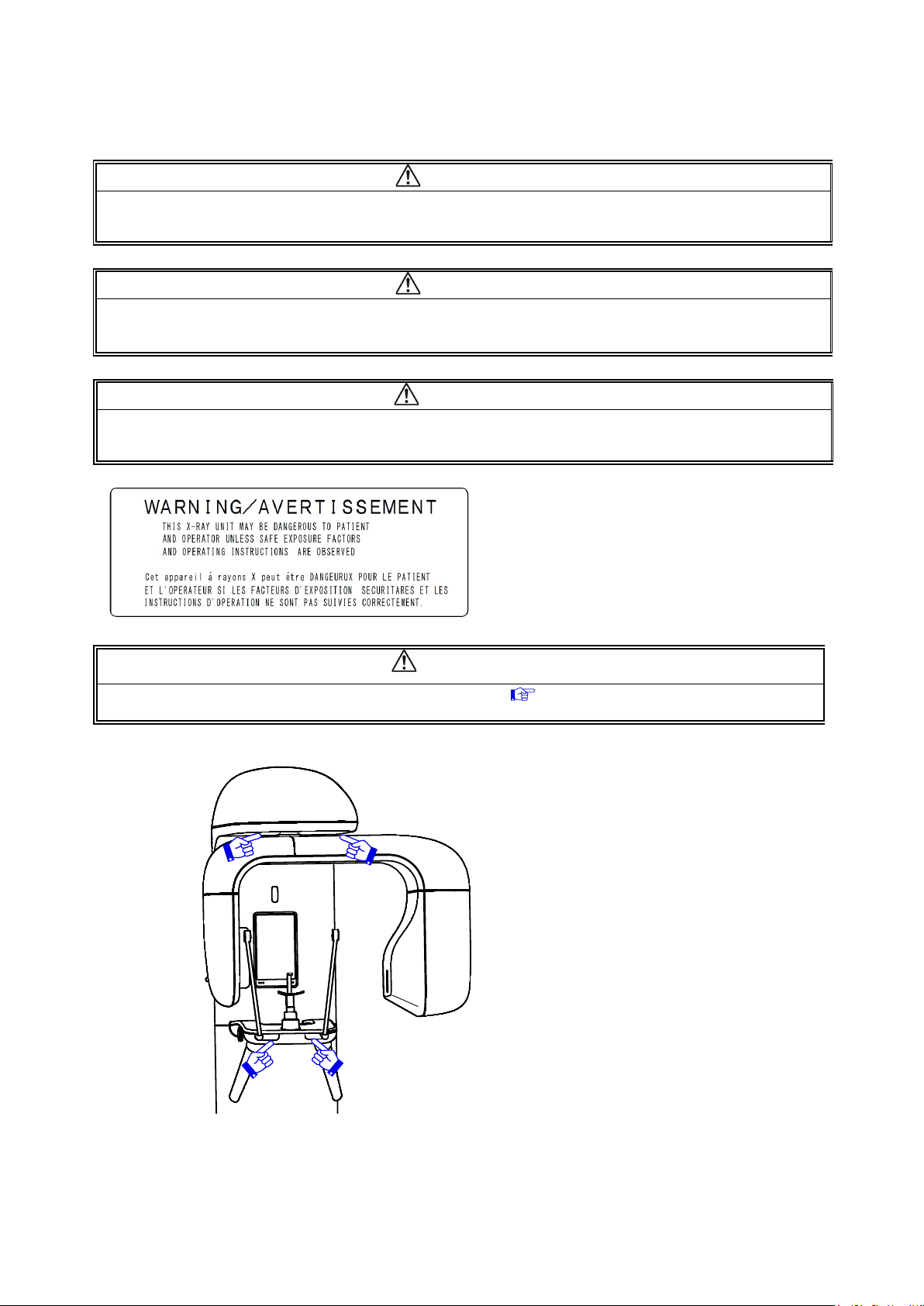
other the patient and assistant authorized by
Ray
WARNING
hen the X-ray is ON, DO NOT allow any person enter into an X-ray room
the doctor.
WARNING
Provide means for audio and Visual communication between the OPERATOR and the PATIENT during an Xexposure.
WARNING
Always monitor the patient, assistant and the equipment during X-ray irradiation.
When any abnormality occurs, release the Exposure switch immediately.
WARNING
Do not bring your fingers close to positions indicated with “ mark”
By the inserting your finger, there is an injury risk.
02-5
Page 12
B02-T216E-A Bel-Cypher Pro
WARNING
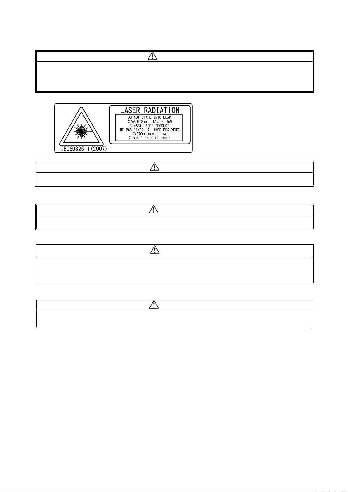
LASER, DOT NOT STARE INTO BEAM, CLASS 1 LASER PRODUCT
1.Laser Beam is applied. For safety, instruct patient not to look into the laser beam.
2.Before the beam is turned on, lower the Frankfurt Plane Beam to the bottom.
3.Do not set the beam pointing into patient's eyes.
CAUTION
When discarding this equipment, please contact your nearest sales office.
CAUTION
Do not turn the Arm Unit by hand. It may cause problems with the equipment.
CAUTION
Operator shall instruct the patient not to move while X-ray exposure is in progress.
Operator shall instruct the patient not to move until the movement of Arm Unit has completed - during
RESET movement.
CAUTION
The equipment shall be connected to a power receptacle marked “Hospital Only” or “Hospital Grade”.
02-6
Page 13
B02-T216E-A Bel-Cypher Pro
of standards emission and the requirement of the
WARNING
Environmental Conditions of EMC (Electromagnetic Compatibility)
The equipment satisfies the EMC (Electromagnetic Compatibility) standard below
: IEC 60601-1-2:2007
Classification of EMI in Accordance with IEC 60601-1-2: 2007
Group 1, Class B
1. The medical electrical equipment needs special precautions regarding EMC and needs to be
installed and put into service according to the EMC information provided in the Operation
manual.
2. The portable and mobile RF communications equipment can affect medical electrical equipment.
3. The use of accessories, transducers and cables other than those specified, with the exception of
transducers and cables sold by the manufacturer of the equipment as replacement parts for
internal components, may result in increased emissions or decreased immunity of the equipment.
4. The cable that suits IEC60601-1-2:2007
immunity are recorded below.
1) Power cable (3m)
2) Exposure Switch cable (10m)
3) LAN cable(type braided shield) for connection with personal computer (10m)
5. The equipment should not be used adjacent to or stacked with other equipment.
8.Basic performance
1) Accuracy of LOADING FACTORS
2) Reproducibility of the RADIATION output
02-7
Page 14
B02-T216E-A Bel-Cypher Pro
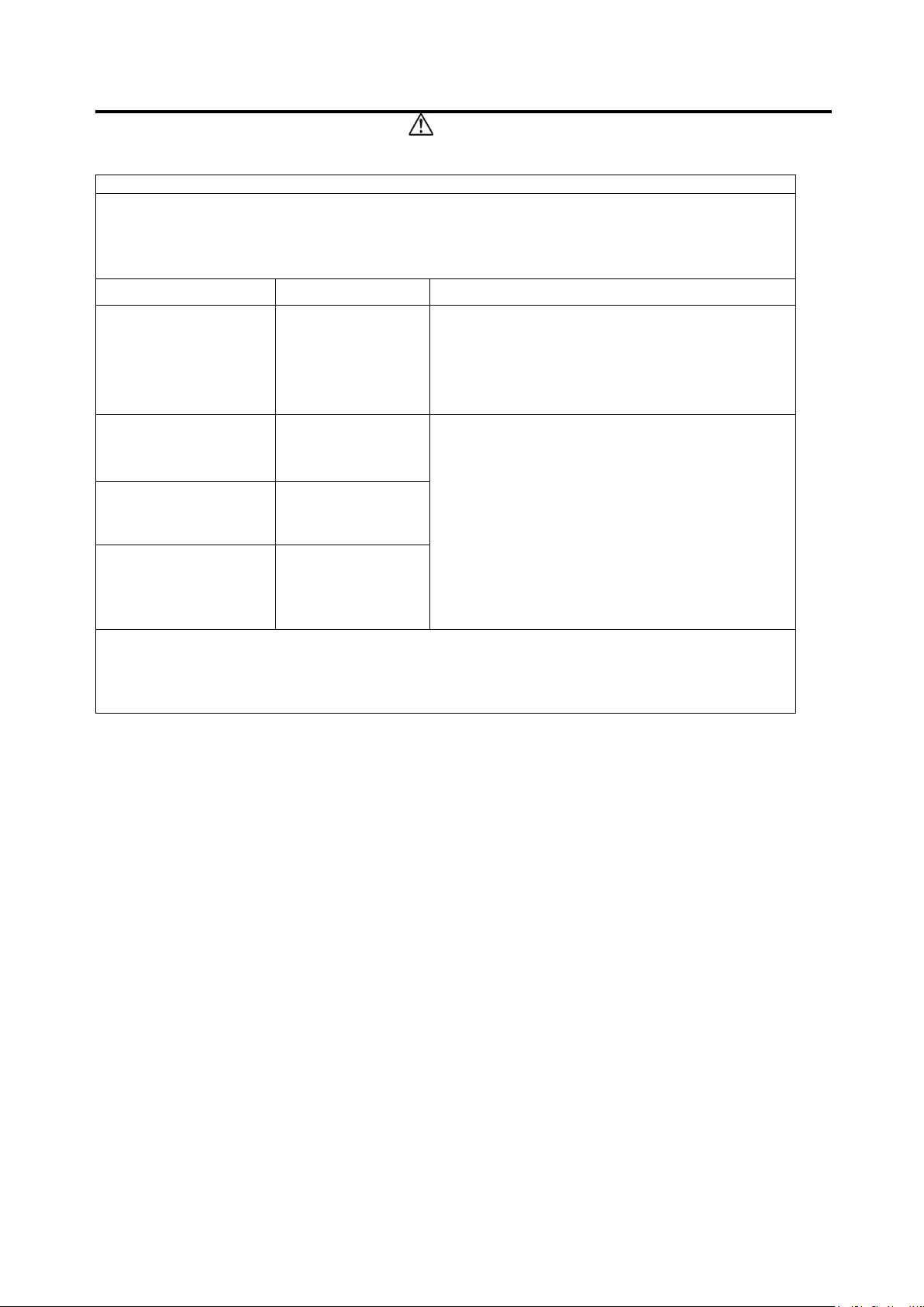
Guidance and
manufacturer’s declaration
– electromagnetic emissions
WARNING
The model Bel-Cypher Pro is intended for use in the electromagnetic environment specified
below. The customer or the user of the model Bel-Cypher Pro should assure that it is used in
such an environment.
Emission test Compliance Electromagnetic environment - guidance
RF emissions
CISPR 11
RF emissions
CISPR 11
Harmonic emissions
IEC61000-3-2
Voltage fluctuations/
Flicker emissions
IEC61000-3-3
Group 1
Class B
Not Applicable
Not Applicable
The model Bel-Cypher Pro uses RF energy only
for its internal function. Therefore,
its RF emissions are very low and are not likely to
cause any interference in nearby
electronic equipment.
The model Bel-Cypher Pro is suitable for use in
all establishments, including domestic
establishments and those directly connected
to the public low-voltage power supply
network that supplies buildings used for
domestic purposes.
02-8
Page 15

B02-T216E-A Bel-Cypher Pro
Guidance and manufacturer
’s declaration
– electromagnetic immunity
WARNING
The model Bel-Cypher Pro is intended for use in the electromagnetic environment specified below.
The customer or the user of the model Bel-Cypher Pro should assure that it is used in such an
environment.
Immunity test
Electrostatic
discharge (ESD)
IEC61000-4-2
Electrical fast
transient/burst
IEC61000-4-4
Surge
IEC61000-4-5
Voltage dips,
short interruptions
and voltage
variations on
power supply
input lines
IEC61000-4-11
Power frequency
(50/60Hz)
magnetic field
IEC61000-4-8
NOTE Ut is the a.c. mains voltage prior to application of the test level.
IEC 60601
test level
±6 kV contact
±8kV air
±2 kV for
power supply
lines
±1 kV for
input/output
lines
±1kV differential
mode
±2kV common
mode
<5% Ut
(>95% dip in Ut)
for 0.5 cycle
40% Ut
(60% dip in Ut)
for 5 cycles
70% Ut
(30% dip in Ut)
for 25 cycles
<5% Ut
(>95% dip in Ut)
for 5 sec
3 A/m 3 A/m Power frequency magnetic fields
Compliance
level
±6 kV contact
±8kV air
±2 kV for
power supply
lines
±1 kV for
input/output
lines
±1kV differential
mode
±2kV common
mode
<5% Ut
(> 95% dip in Ut)
for 0.5 cycle
40% Ut
(60% dip in Ut)
for 5 cycles
70% Ut
(30% dip in Ut)
for 25 cycles
<5% Ut
(>95% dip in Ut)
for 5 sec
Electromagnetic environment
Floors should be wood, concrete or
ceramic tile. If floors are covered with
synthetic material, the relative humidity
should be at least 30%.
Mains power quality should be that
of a typical commercial or hospital
environment.
Mains power quality should be that
of a typical commercial or hospital
environment
Mains power quality should be that
of a typical commercial or hospital
environment
should be at levels characteristic
of a typical location in a typical
commercial or hospital environment
- guidance
02-9
Page 16
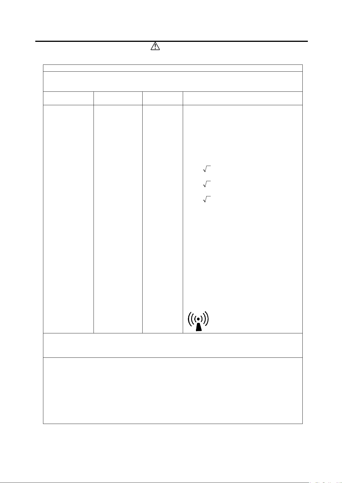
B02-T216E-A Bel-Cypher Pro
Guidance and manufacturer’s declaration
– electromagnetic immunity
Immunity test
IEC 60601 test
Compliance
Electromagnetic environme
nt
The model Bel-Cypher Pro is intended for use in the electromagnetic environment specified
below. The customer or the user of the Bel-Cypher Pro should assure that it is used in such an
environment.
WARNING
Conducted RF
IEC61000-4-6
Radiated RF
IEC61000-4-3
3 Vrms
150kHz to
80MHz
3 V/m
80MHz to
2.5 GHz
level
level
3 Vrms
3 V/m
- guidance
Portable and mobile RF communications
equipment should be used no closer to any
part of the Bel-Cypher Pro, including cables,
than the recommended separation distance
calculated from the equation applicable to
the frequency of the transmitter.
Recommended separation distance
d =1,2
P
d =1,2P 80 MHz to 800 MHz
d =2,3
800 MHz to 2.5 GHz
P
where P is the maximum output power rating
of the transmitter in watts(W) according to
the transmitter manufacturer and d is the
recommended separation distance in
metres(m).
Field strengths from fixed RF transmitters,
as determined by an electromagnetic site
survey, ashould be less than the compliance
level in each frequency range.b
Interference may occur in the vicinity of
equipment marked with the following
symbol:
NOTE 1 At 80 MHz and 800 MHz, the higher frequency range applies.
NOTE 2 These guidelines may not apply in all situations. Electromagnetic propagation is
affected by absorption and reflection from structures, objects and people.
a
Field strengths from fixed transmitters, such as base stations for radio (cellular/cordless)
telephones and land mobile radios, amateur radio, AM and FM radio broadcast and TV
broadcast cannot be predicted theoretically with accuracy. To assess the electromagnetic
environment due to fixed RF transmitters, an electromagnetic site survey should be
considered. If the measured field strength in the location in which the Bel-Cypher Pro is used
exceeds the applicable RF compliance level above, the Bel-Cypher Pro should be observed to
verify normal operation. If abnormal performance is observed, additional measures may be
necessary, such as reorienting or relocating the Bel-Cypher Pro.
b
Over the frequency range 150 kHz to 80 MHz, field strengths should be less than 3 V/m.
02-10
Page 17
B02-T216E-A Bel-Cypher Pro
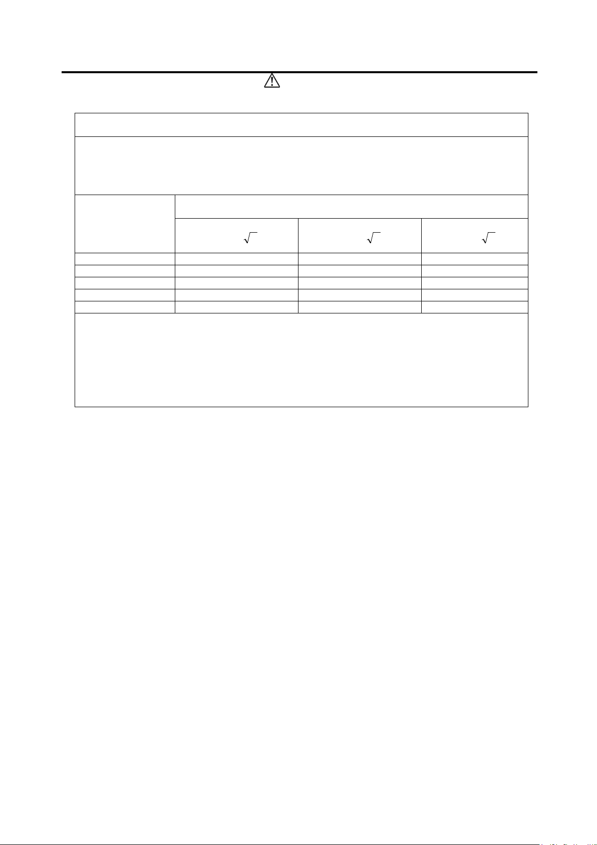
Recommende
d separation distances between
R
ated maximum
Separation distance according to frequency of transmitter
150 kHz to 80 MHz
80 MHz to 800 MHz
800 MHz to 2.
5 GHz
WARNING
portable and mobile RF communications equipment and the Bel-Cypher Pro
The Bel-Cypher Pro is intended for use in an electromagnetic environment in which radiated RF
disturbances are controlled. The customer or the user of the Bel-Cypher Pro can help prevent
electromagnetic interference by maintaining a minimum distance between portable and mobile RF
communications equipment (transmitters) and the Bel-Cypher Pro as recommended below,
according to the maximum output power of the communications equipment.
output power of
transmitter
W
0.01 0.12 0.12 0.23
0.1 0.38 0.38 0.72
1 1.20 1.20 2.30
10 3.79 3.79 7.27
100 12.00 12.00 23.00
For transmitters rated at a maximum output power not listed above, the recommended separation
distance
transmitter, where P is the maximum output power rating of the transmitter in watts(W) according to
the transmitter manufacturer.
NOTE 1 At 80 MHz and 800 MHz, the separation distance for the higher frequency range applies.
NOTE 2 These guidelines may not apply in all situations. Electromagnetic propagation is affected
d
in meters (m) can be estimated using the equation applicable to the frequency of the
by absorption and reflection from structures, objects and people.
d
=1,2P
m
d
=1,2P
d
=2,3P
02-11
Page 18

B02-T216E-A Bel-Cypher Pro
03
03.Explanation of Equipment
1. Outline
Bel-Cypher Pro can take radiographs of Panoramic and TMJ.
2. Indications for Use (Describe)
The Bel-Cypher Pro dental panoramic X-ray system is indicated for use as a generator
of radiographic images of the dento-maxilofacial region and is intended for dental
examination and diagnosis of diseases of the teeth, jaw, and oral structures.
3. Features
3. 1. High Frequency X-ray Generator
The X-ray generator uses a High Frequency Inverter to delivers high quality radiation.
This enables improved image quality while reducing the radiation dose.
3. 2. X-ray Tube with minute focus spot size
Owing to the minute X-ray Tube focus spot size of 0.5mm, sharp and clear images are
achieved.
3. 3. Versatile Combination of Exposure Factors
Tube voltage can be set from 60 kV to 80 kV in 1 kV step.
Tube current can be set at 2, 2.5, 3, 3.2, 4, 5, 6, 6.3, 7, and 8mA.
With wide range of exposure settings, Bel-Cypher Pro can obtain the ideal radiograph for
every type of patient.
3. 4. Patient Positioning with 3 Beam Lines
Bright and easy-to-see three laser beams make positioning very easy and accurat
e.
4. Configuration
Equipment consists of the assemblies outlined below.
1. Mechanical Assemblies, 2. X-ray Generator, 3. X-ray Controller
03-1
Page 19

B02-T216E-A Bel-Cypher Pro
04
04.Specifications
General name Digital Panoramic Radiograph
Model Bel-Cypher Pro
Power Voltage
Power Capacity 9A
High Tension Generator High Tension Generator (100kHz)
X-ray Tube Voltage 60kV to 80kV (1kV step)
X-ray Tube Current 2 to 8mA (1mA step and R’10 series)
Exposure method Manual
X-ray Tube D-052SB (Toshiba)
X-ray Tube Focal Spot 0.5 mm
Total Filtration 2.5mmAl (minimum)
Radiographic Mode
Exposure Time
Magnification Ratio
Image receiver Digital Sensor
Beam for patient positioning 3 beams
120V AC 60Hz 1ɸ 0.3Ω
Panorama (Adult, Child), Panoramic Bitewing (Adult, Child),
TMJ
Panorama: 10 sec. Panoramic Bitewing: 2.3 sec. (x 2)
TMJ: 2.5 sec. (x 4)
Panorama: 1.2 to 1.3, Panoramic Bitewing: 1.2 to 1.3
TMJ: 1.2
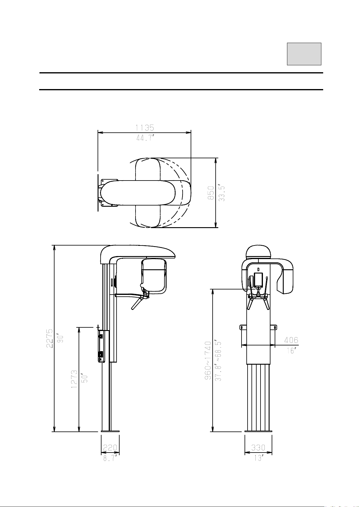
Dimension W:850mm x D:1,135mm x H:2,275mm
Weight Approximately 231lb (105 kg)
Environmental conditions for Operation
Temperature : 41 to 95F (5 to 35℃)
Humidity : 30 to 85%
Pressure : 700 to 1060 hpa
Environmental conditions for Storage
Temperature : 14 to 140F (-10 to 60℃)
Humidity : 10 to 95%
Pressure : 700 to 1060 hpa
Environmental conditions for Transportation
Temperature : 14 to 140F (-10 to 60℃)
Humidity : 10 to 95%
Pressure : 700 to 1060 hpa
04-1
Page 20
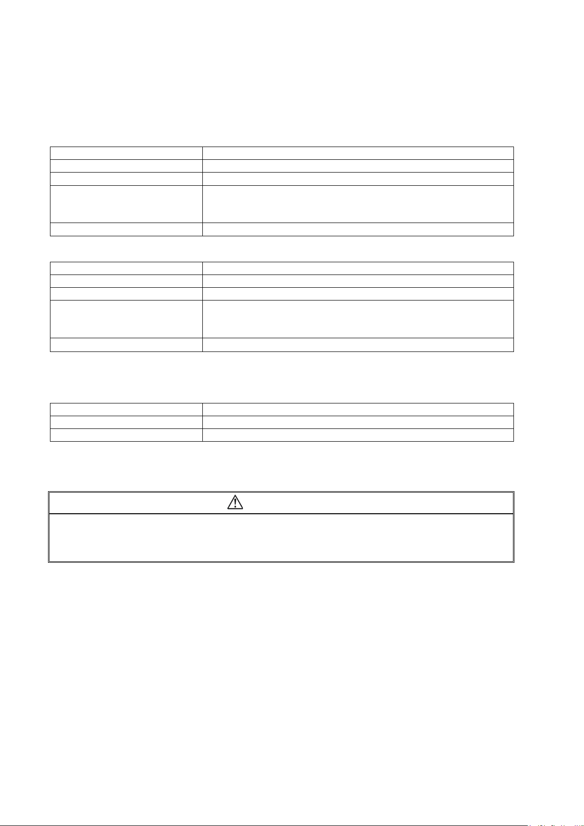
B02-T216E-A Bel-Cypher Pro
CPU
Video Controller
Memory
OS Windows 7 Professional
64-bit, English Version
Other
CPU
Video Controller
Memory
OS Windows 7 Professional
64-bit, English Version
resolution
Grayscale Tones
256 tones
Display Colors
16.77 million :
supported
8-
bit
CAUTION
Recommended specifications of Personal Computer
Recommended PC specifications
Intel Core i7-6600U (2.6GHz) or later
NVIDIA GeForce 930M or more, or equivalent
16GB or more
Windows 8 Professional 64-bit, English Version
Windows 10 Professional 64-bit, English Version
Ethernet ×1 (1000BASE-T)
Minimum PC specifications
Intel Core i5-6300U (2.4GHz) or later
Intel HD Graphics 520 or more, or equivalent
8GB or more
Windows 8 Professional 64-bit, English Version
Windows 10 Professional 64-bit, English Version
Other
※ Use a LAN cable of Category 5e or better
Recommended specifications of the image display monitor
Ethernet ×1 (1000BASE-T)
1920×1080
PC and monitor are required to meet the international IEC60950-1 or IEC60601-1 standard.
If you run software that heavily loads the PC, transfer & acquisition of images could be interrupted.
Please schedule Windows updates or virus scan updates to be performed outside clinic hours.
04-2
Page 21
B02-T216E-A Bel-Cypher Pro
05
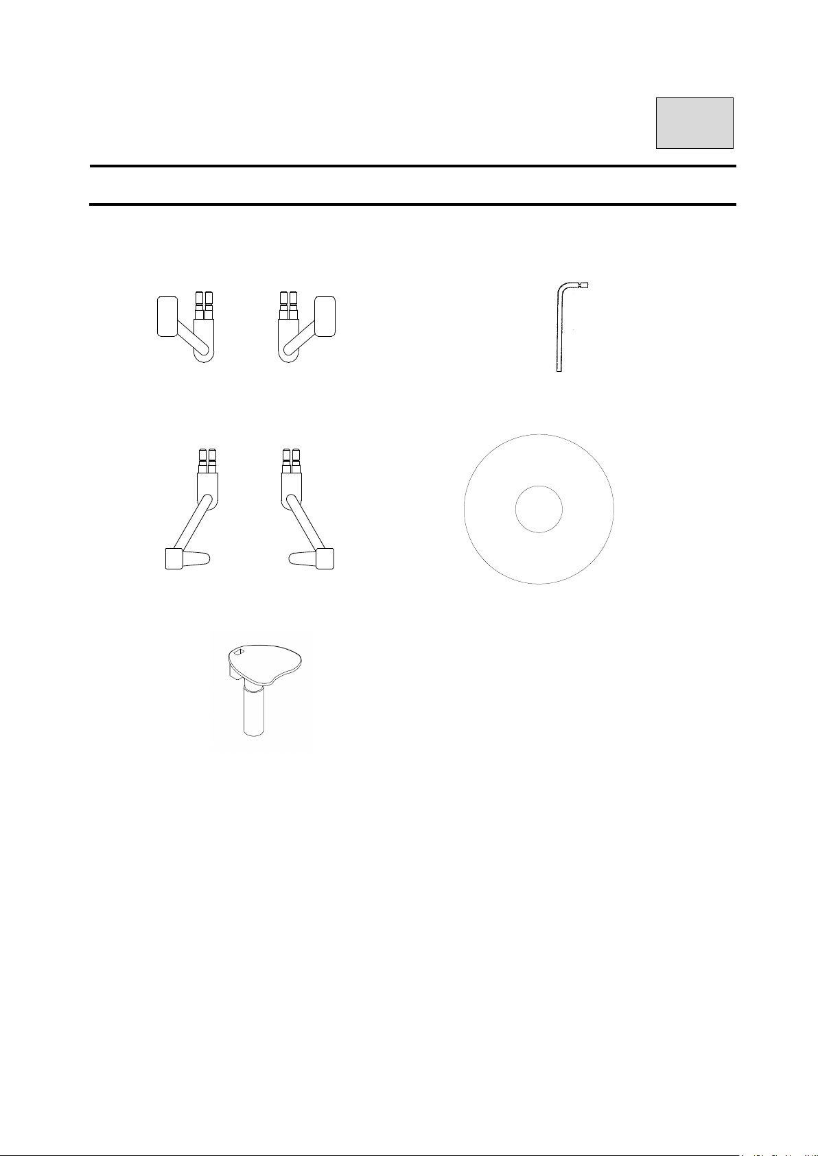
05.Standard Accessories
1. Temporal supports (Panorama)
2.Ear Rods (TMJ 4 sections) 5.TWAIN Driver Installer
4.Bite Block (Panorama)
Bel-Cypher Pro
TWAIN Driver Installer No.***
3.Chinrest (Panorama)
SERIAL No.*********
CMOS SENSOR No.********
05-1
Page 22
B02-T216E-A Bel-Cypher Pro
detector
06
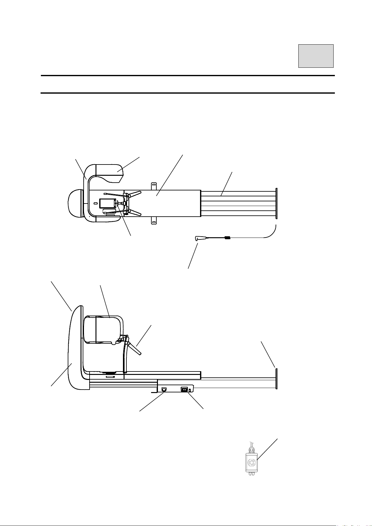
06.Names of the Major Components
Rotation Unit
Control Unit
Arm Unit
Image
X-Ray source Unit
Rest Unit
Grip
Emergency Stop
Switch
Sliding Unit
Stand
Exposure Switch
Power Switch
Base
Emergency Stop
Switch (Option)
06-1
Page 23
B02-T216E-A Bel-Cypher Pro
07
07. Explanation of each part
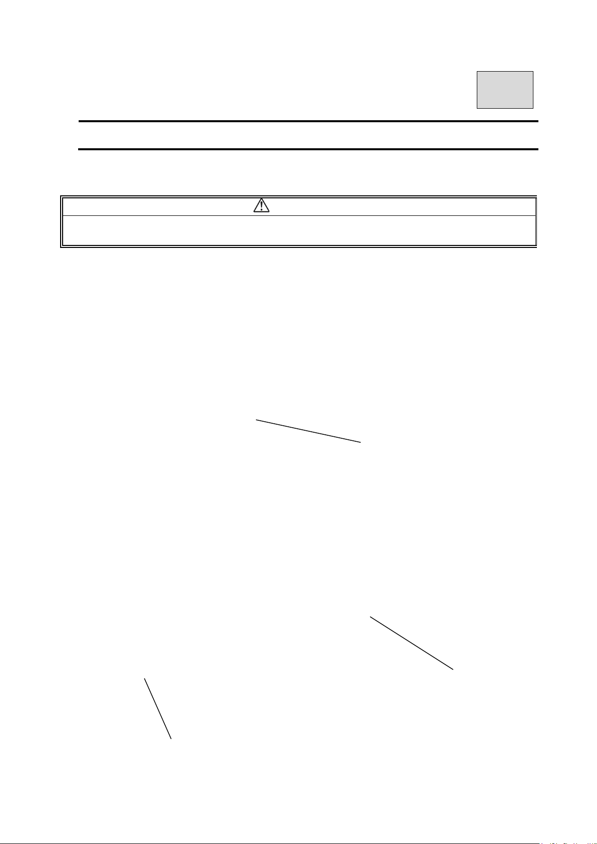
1. Power Switch
CAUTION
To protect this equipment, after turning the power on, wait 5 seconds before turning the power off.
After turning the power off, wait 5 seconds before turning the power on.
Push “I“ on the power switch to turn the power ON.
Push “○“ on the power switch to turn the power OFF.
2. Emergency Stop Switch
Use this switch at an emergency.
It works by pressing the switch.
If you want to cancel, turn in the direction of the arrow.
Emergency Stop Switch
Power Switch
Emergency Stop Switch
07-1
Page 24
B02-T216E-A Bel-Cypher Pro
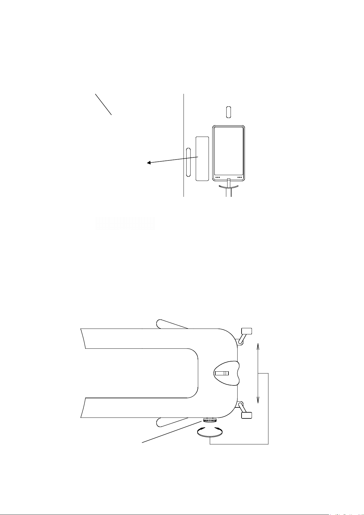
3. Operation Panel
See the 08.Operation Panel for more information.
Operation Panel
4. Adjuster Knob
Temporal supports(for Panoramic) and Ear Rods(for TMJ) are used to hold the
sides of the patient’s head. The Adjuster knob is used to open or close Temporal
supports or Ear Rods.
Adjuster Knob
07-2
Page 25
B02-T216E-A Bel-Cypher Pro
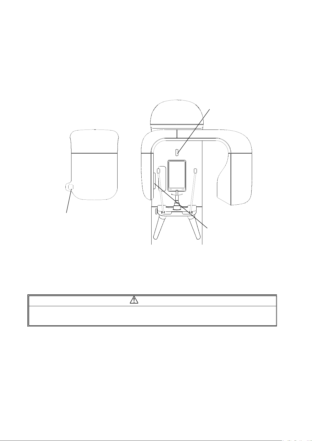
5. Names of Patient Positioning Laser Beams
Three Laser Beams are used for Patient Positioning
Median Beam: Adjust the center of the patient’s face,
Frankfurt Plane Beam: Adjust the Frankfurt Horizontal Plane of a patient
Focus Beam: Adjust the positions of the roots of upper and lower anterior teeth
Focus Beam
Median Beam
Frankfurt Plane Beam
CAUTION
1. Laser Beams are used to position the patient.
2. Warn the patient not to look directly into the laser beam.
3. Do not set the beam line so that it is aligns with the patient’s eyes.
07-3
Page 26
B02-T216E-A Bel-Cypher Pro
08
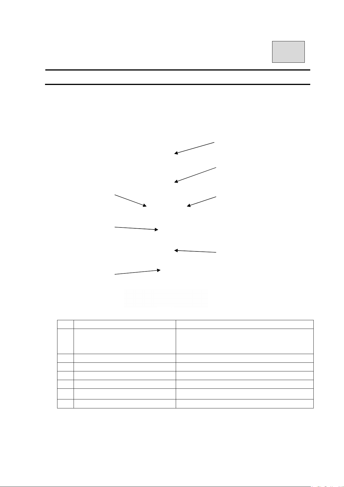
08. Operation Panel
1. Explanation of Operation Panel
No Name Function
1
Reset Switch
2 Ready Switch Start ready
3 Focus Beam Backward Move Focus Beam Backward
4 Focus Beam Forward Move Focus Beam Forward
5 Sliding Unit Up
6
Sliding Unit Down Loweres the sliding unit
7
Exposure Mark Mark is lit during exposure
⑤
⑦
①
②
③ ④
⑥
Set Arm Unit to start position
Reset Error
Reset Read On
Raises the sliding unit
08-1
Page 27

B02-T216E-A Bel-Cypher Pro
09
09. Preparation before Exposure
1. Prepare accessories according to exposure mode
1. 1. Panorama
1)A pair of Temporal supports (Panorama)
2)A Chinrest (Panorama)
3)A Bite Block
1. 2. TMJ Lateral 4 sections
A pair of Ear Rods (TMJ Lateral 4 sections)
2. Make patient wear X-ray protective clothing
09-1
Page 28
B02-T216E-A Bel-Cypher Pro
10
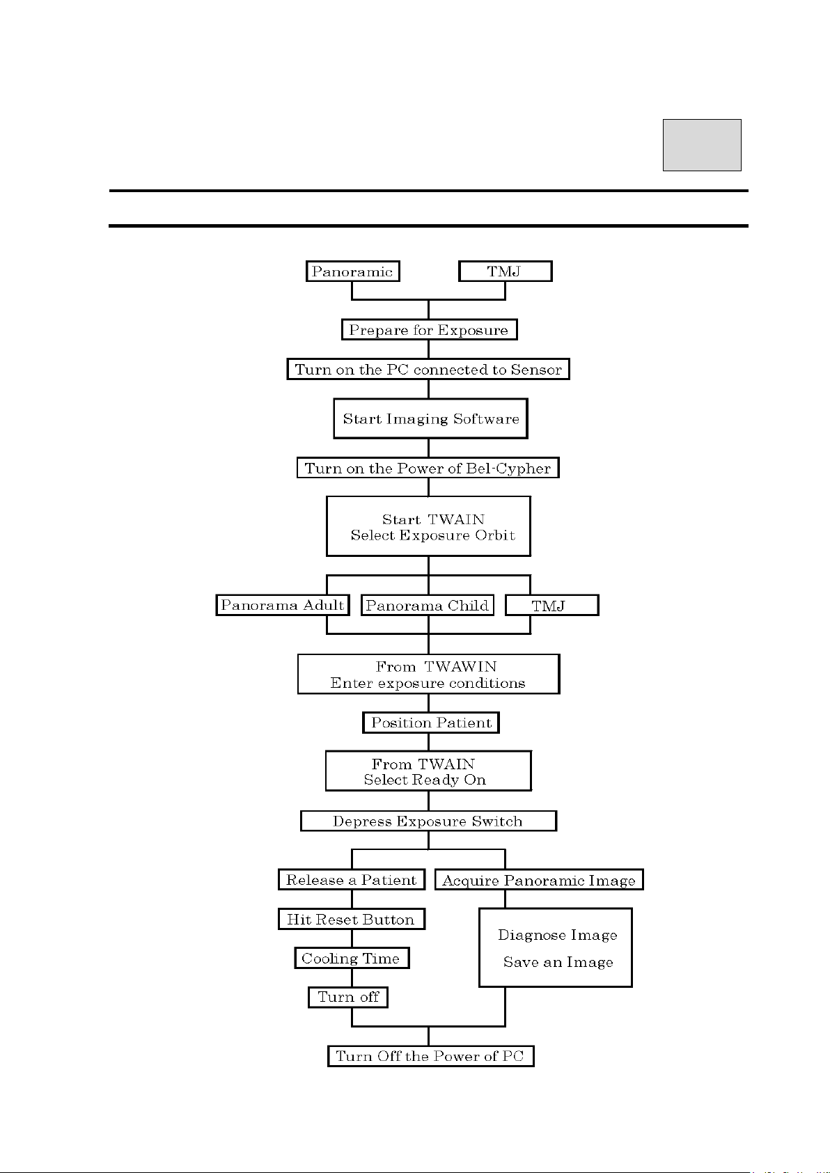
10. Flow Chart of Exposure
10-1
Page 29

B02-T216E-A Bel-Cypher Pro
11
11.Operation Procedure for Panorama
& Panoramic Bitewing
1. Learn Panoramic radiographic operation procedure this is basic X-ray radiography.
2. Explanation of operation procedure in other modes that the same operation as
Panorama has been omitted. Refer to the operation procedure for Panorama accordingly.
1. Preparation for exposure
1. 1.
*X-ray protective clothing
*Temporal supports for Panorama
*Chinrest for Panorama
*Bite block
2.Turn on the Power of the Bel-Cypher Pro
2. 1. Push “I“ on the power switch to turn the power ON.
Power Switch
11-1
Page 30
B02-T216E-A Bel-Cypher Pro
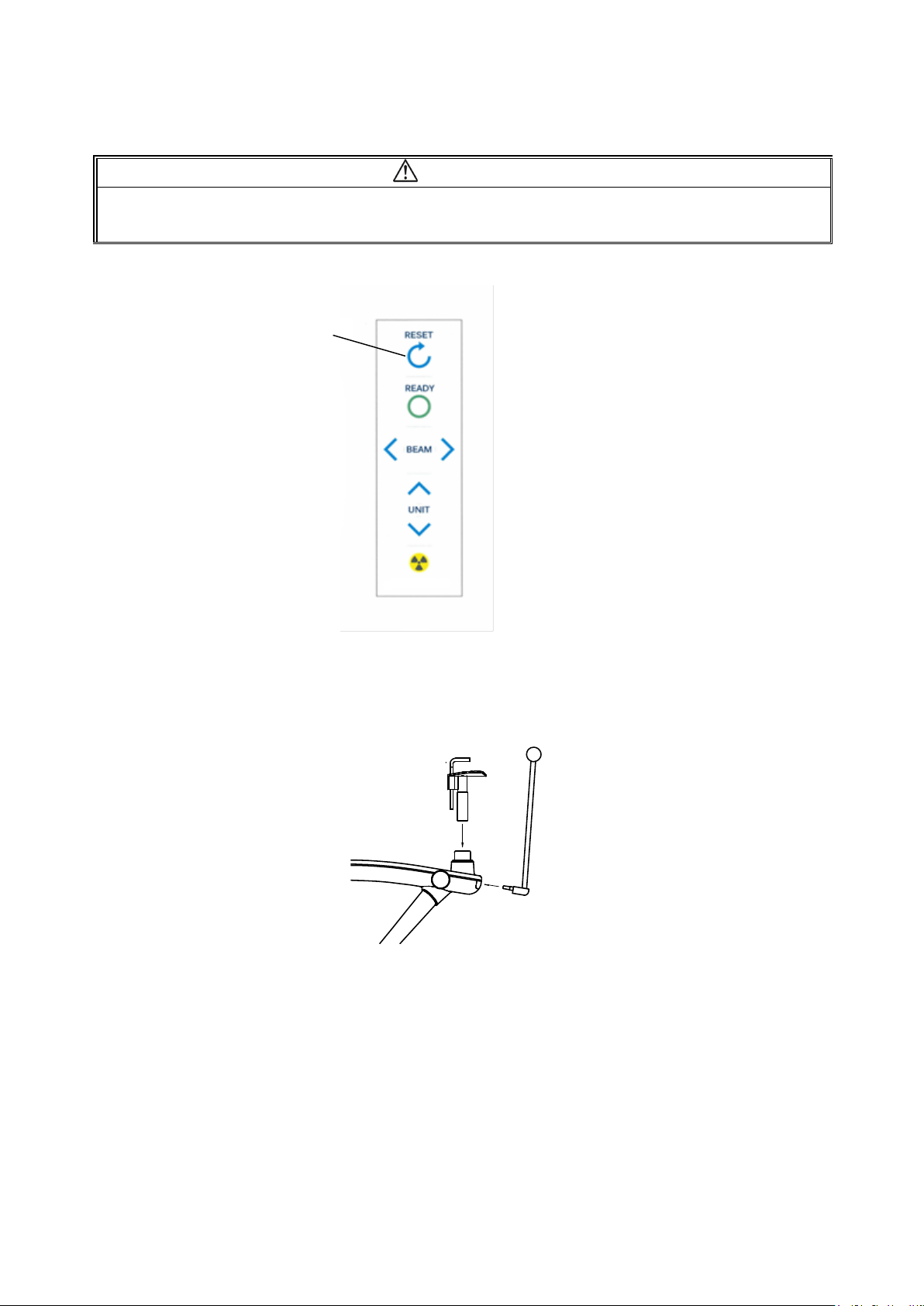
2. 2. If Arm Unit is not at its Reset Position, hit Reset Switch.
CAUTION
Before hitting the Reset Switch, remove the Chinrest and Temporal supports.
By hitting the Reset Switch, the Arm starts to rotate. Stay away from Rotation area to avoid injury.
2. 3. Attach the Chinrest and Temporal supports.
3.Exposure settings
Start-up of imaging software
Start the imaging software from the management software.
Reset Switch
11-2
Page 31
B02-T216E-A Bel-Cypher Pro
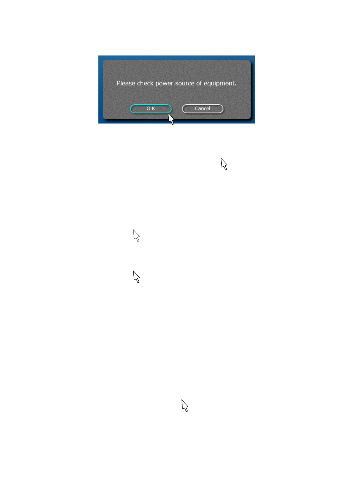
Check Power
If the equipment has already turned on, click OK.
RESET
Click "Reset" to return the equipment arm to its original position.
Choose either Adult or Child.
Selected mode will be highlighted.
Set ON/OFF setting for Tomosynthesis.
When the [Tomosynthesis] button is highlighted, the Tomosynthesis function is ON. With the
Tomosynthesis function ON, image processing takes longer, compared to when the function is OFF.
NOTE:
“Tomosynthesis” means the function which is used to acquire images of multiple tomographic layers in
a single exposure.
11-3
Page 32
B02-T216E-A Bel-Cypher Pro
If you want Panoramic Bitewing, choose “Bitewing”.
*Tomosynthesis and Bitewing cannot be used together.
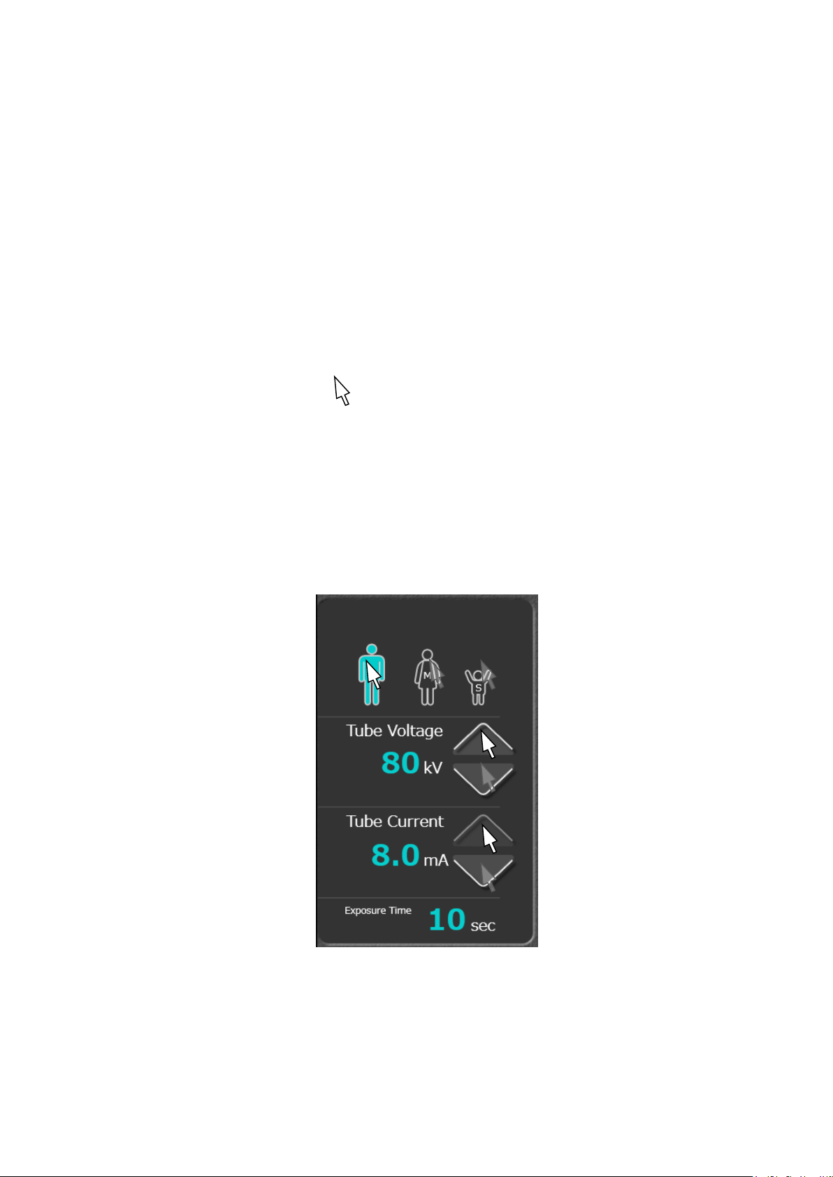
Voltage (kV) and current (mA) settings
Refer Sec 13 Table of Exposure Settings to choose appropriate setting values.
- Discretionary setting
kV setting
Click the (UP) or (DOWN) symbols on the right side of the kV display.
mA setting
Click the (UP) or (DOWN) symbols on the right side of the mA display.
Or simply click patient size icon.
You may need to adjust mA / kV for some patients.
11-4
Page 33
B02-T216E-A Bel-Cypher Pro
4. Patient Positioning
Patient positioning is the key for a successful radiograph. Position the patient with care.
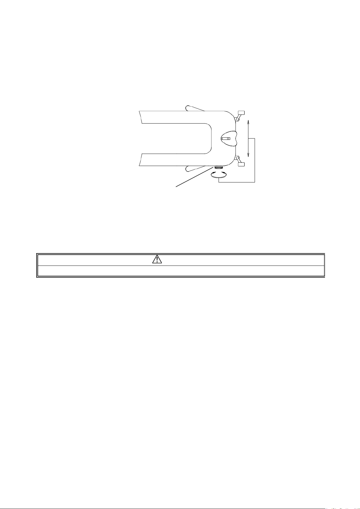
4. 1. By turning adjuster Knob, open the Temporal supports.
4. 2. Ensure the patient is wearing X-ray protective clothing.
Adjuster Knob
CAUTION
Ensure both the patient and assistant are wearing X-ray protective clothing.
4. 3. Bring the patient close to the Bel-Cypher Pro.
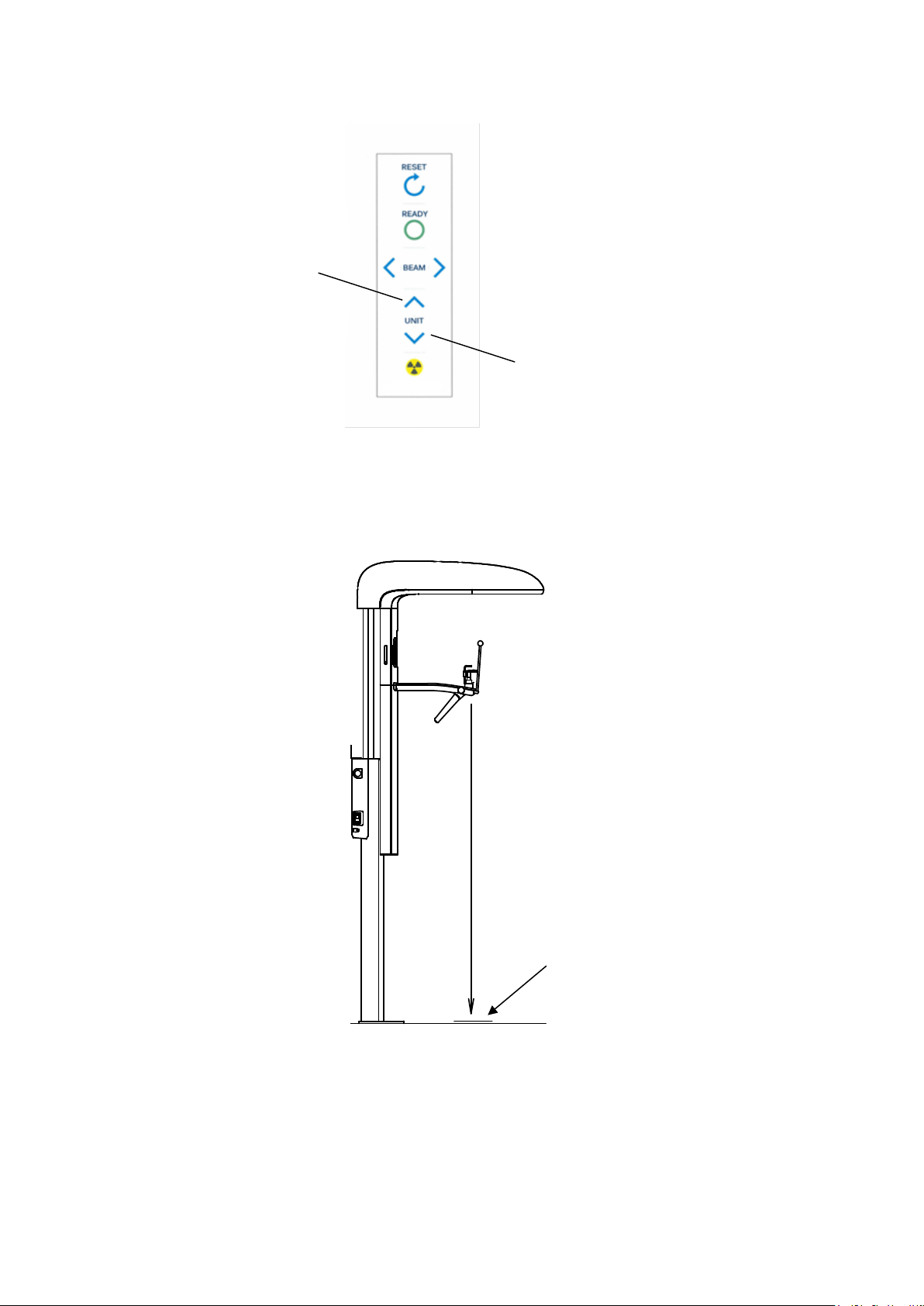
4. 4. Adjust the height of Chinrest by moving Sliding Unit Up/Down, so that the patient
can stand upright and the patient’s chin can rest on the Chinrest.
11-5
Page 34
B02-T216E-A Bel-Cypher Pro
Sliding Unit Up
Sliding Unit Down
4.5.Bring patient to stand at the foot position as shown below.
4.6.Ask patient to hold the grips.
4.7.Bring Chinrest (Panorama) until the Chinrest lightly touches the patient’s lower jaw.
11-6
Foot Position
Page 35
B02-T216E-A Bel-Cypher Pro
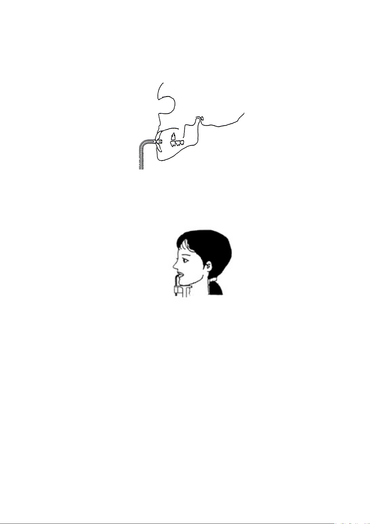
4.8.Instruct patient to bite the groove of the Bite Block with upper and lower anterior teeth.
Instruct patient to put chin on the Chinrest.
For an edentulous patient
Roll clean gauze on Bite Block, and instruct patient to bite onto it.
11-7
Page 36
B02-T216E-A Bel-Cypher Pro
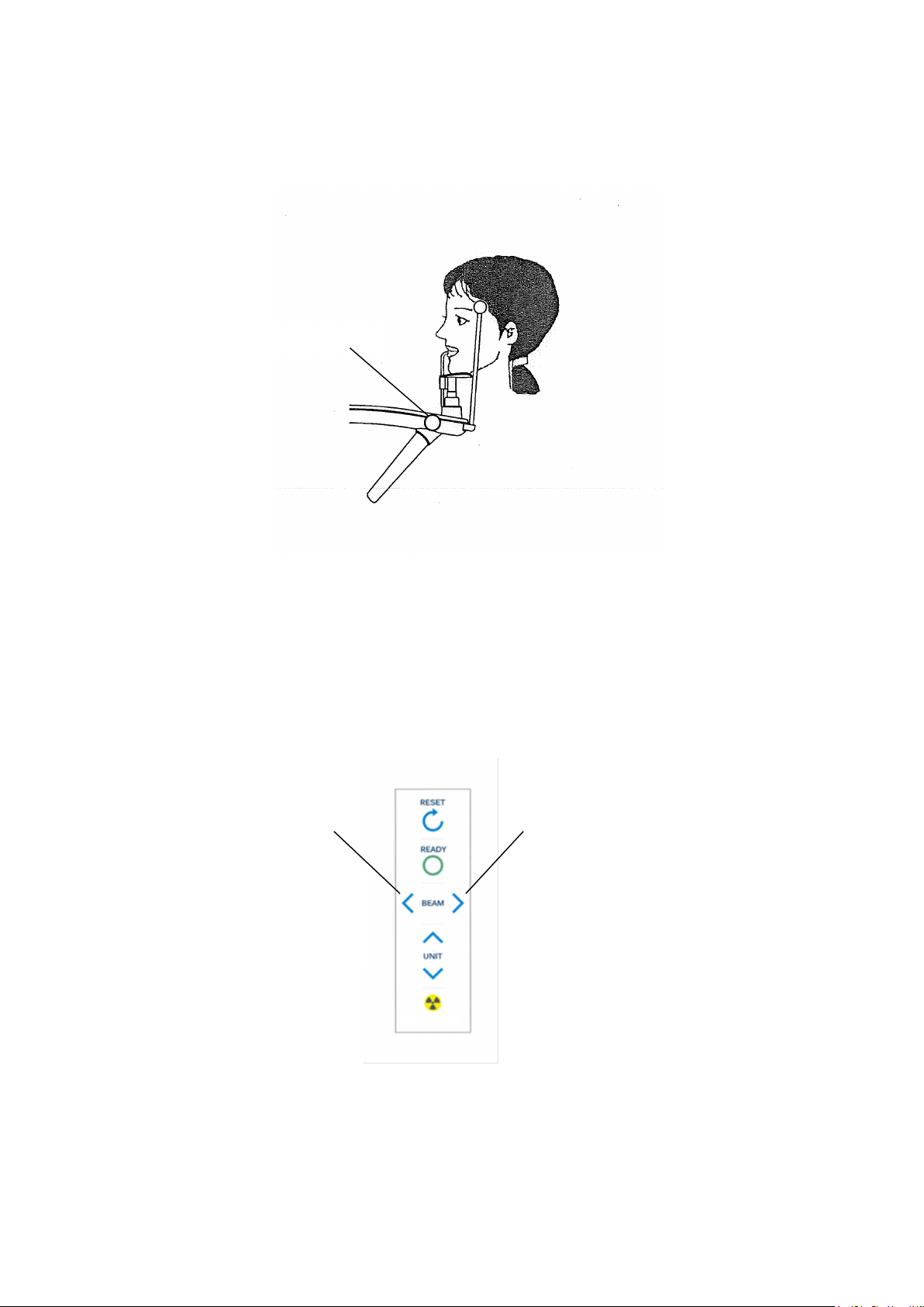
4.9.Lightly close the Temporal supports to position patient’s head.
4.10.Turn Focus Beams ON
Adjuster Knob
Depress either Focus beam switch to turn Patient Focus Beams on.
Focus Beam Switch
Focus Beam Switch
11-8
Page 37
B02-T216E-A Bel-Cypher Pro
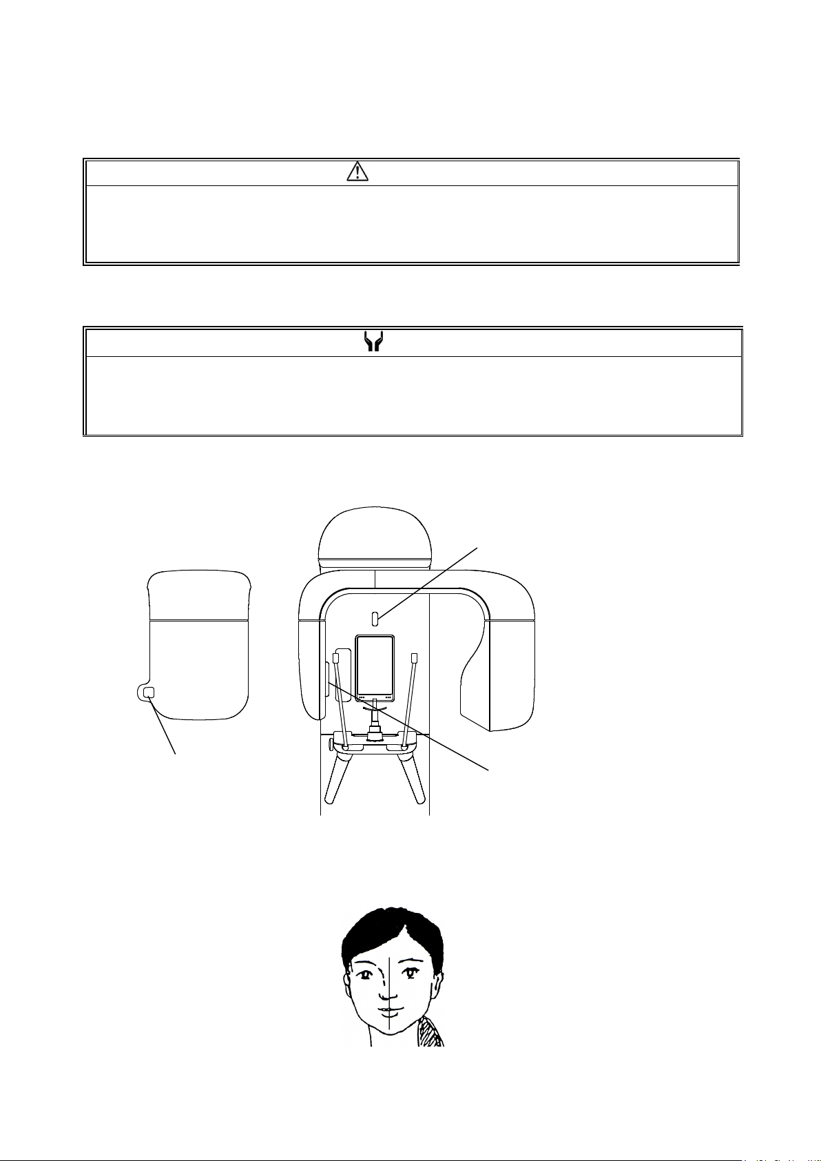
ositioning beams have AUTO POWER OFF function. Laser beam will be automatically turned off a few
4.11.Median Beam, Frankfurt Plane Beam & Focus Beam turn on at the same time.
CAUTION
1. Warn patient not to look directly into the beam of the laser.
2. Do not set the beam into the patient’s eyes.
NOTE
P
minutes after the beam turned ON.
In order to turn the laser on again, depress either Focus beam switch.
Focus Beam
4.12.Adjust the patient’s head so that the Median Beam comes to the center of the patient’s face.
Median Beam
Frankfurt Plane Beam
11-9
Page 38
B02-T216E-A Bel-Cypher Pro
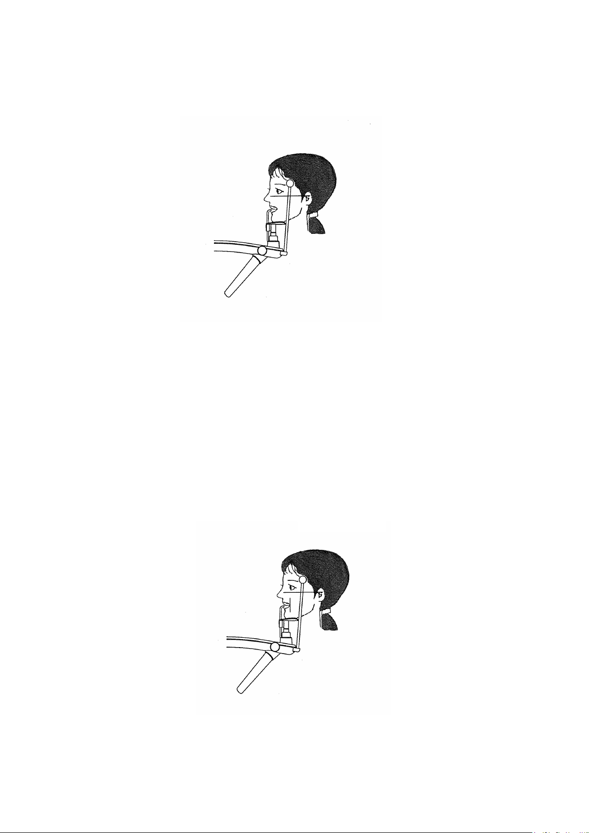
4.13.Move Frankfurt Plane Beam to align Frankfurt Plane Beam with Frankfurt Plane of the
patient’s head.
4.14.Carefully close Temporal supports to support the patient’s head.
4.15.Align Focus Beam with roots of upper and lower anterior teeth.
Focus Beam
For an edentulous patient
Roll clean gauze on Bite Block, and instruct patient to bite it.
4.16. When aligning the Focus Beam, look at patient from the side.
11-10
Page 39

B02-T216E-A Bel-Cypher Pro
for 6 min, sensor is shut
NOTE
If device is not operated by Operation Panel nor communicated by software
down with displaying message on software and software is closed.
11-11
Page 40
B02-T216E-A Bel-Cypher Pro
5.Ready On
1) Click "Ready" on the PC operation panel.
The color of the message of PC operation panel changes to green color and blinks.
The message "Sensor is being initialized" is displayed.
After finishing initialization of the sensor, the color of the message of the PC operation panel
changes to green. The message “Start exposure” is displayed.
NOTE
1.After “Start Exposure” is displayed, if the Exposure switch is not depressed within 30 seconds,
“Ready On” will be cancelled automatically.
2.Any key operation except Reset key cannot be operated during Ready On、to cancel Ready On,
hit Reset key.
3.If Arm is not at “Reset position”, even if ready key is depressed, Read On won’t be displayed.
hit Reset key to bring the Arm to the “Reset position”.
11-12
Page 41
B02-T216E-A Bel-Cypher Pro
. Operator must stand
will stop
ll lose the
6. X-Ray Irradiation
WARNING
1.Other people except patient and operator should be outside the X-ray room.
2.The X-ray exposure switch should be depressed 7 feet away from Bel-Cypher Pro
behind the shielded partition.
3.Carefully observe patient while X-ray is irradiated, release the Exposure Switch immediately
if any trouble occurs.
4.Instruct patient not to move while X-ray is in progress.
WARNING
1.The Exposure switch is a ‘Deadman’ type. X-ray irradiation and the movement of the Arm Unit
immediately when the Exposure Switch is released.
Keep the Exposure Switch depressed until the exposure is completely finished (indicated by
a final beep then silence).
If you release the Exposure Button before the completion of the exposure, you’
image.
2.If exposure switch is released while an X-ray operation is in progress, release the patient and depress
Reset key to bring Arm Unit to the start position. Start from the beginning again.
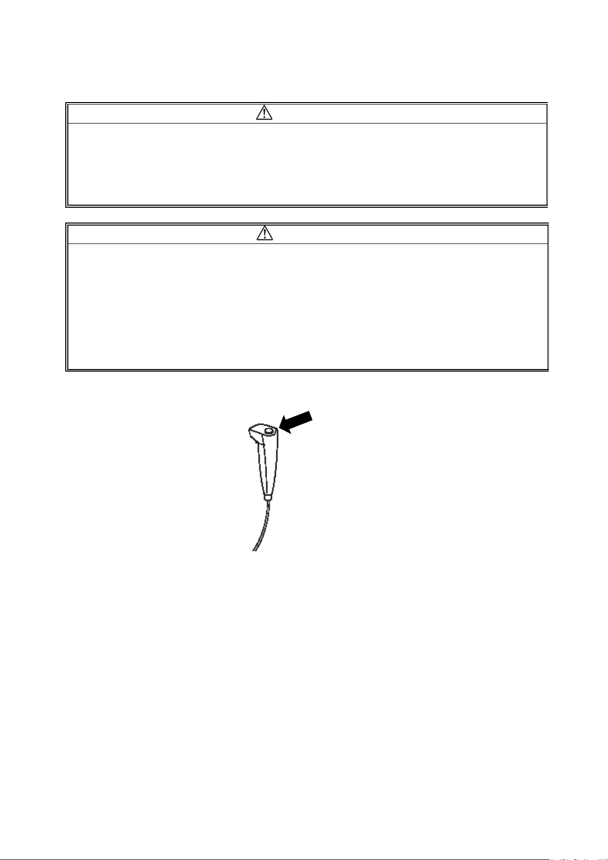
6.1.Keep the Exposure Switch pressed until the end of the Exposure.
6.2.The Arm rotates, a buzzer sounds intermittently, and exposure begins.
During exposure, the message on the PC operating panel blinks in yellow, and "Under the
X-ray exposing" is displayed.
11-13
Page 42
B02-T216E-A Bel-Cypher Pro
⑤
⑥ ③
③
6.3.When irradiation is completed, arm rotation stops and buzzer stops sounding.
6.4.”Transferring Data” is displayed on the PC Screen.
CAUTION
While data is transferring, do not turn off the power of Bel-Cypher Pro, or else data will be lost.
6.5.After data is transferred, Panoramic Image is displayed on the screen.
6.6.Tomosynthesis
6.6.1
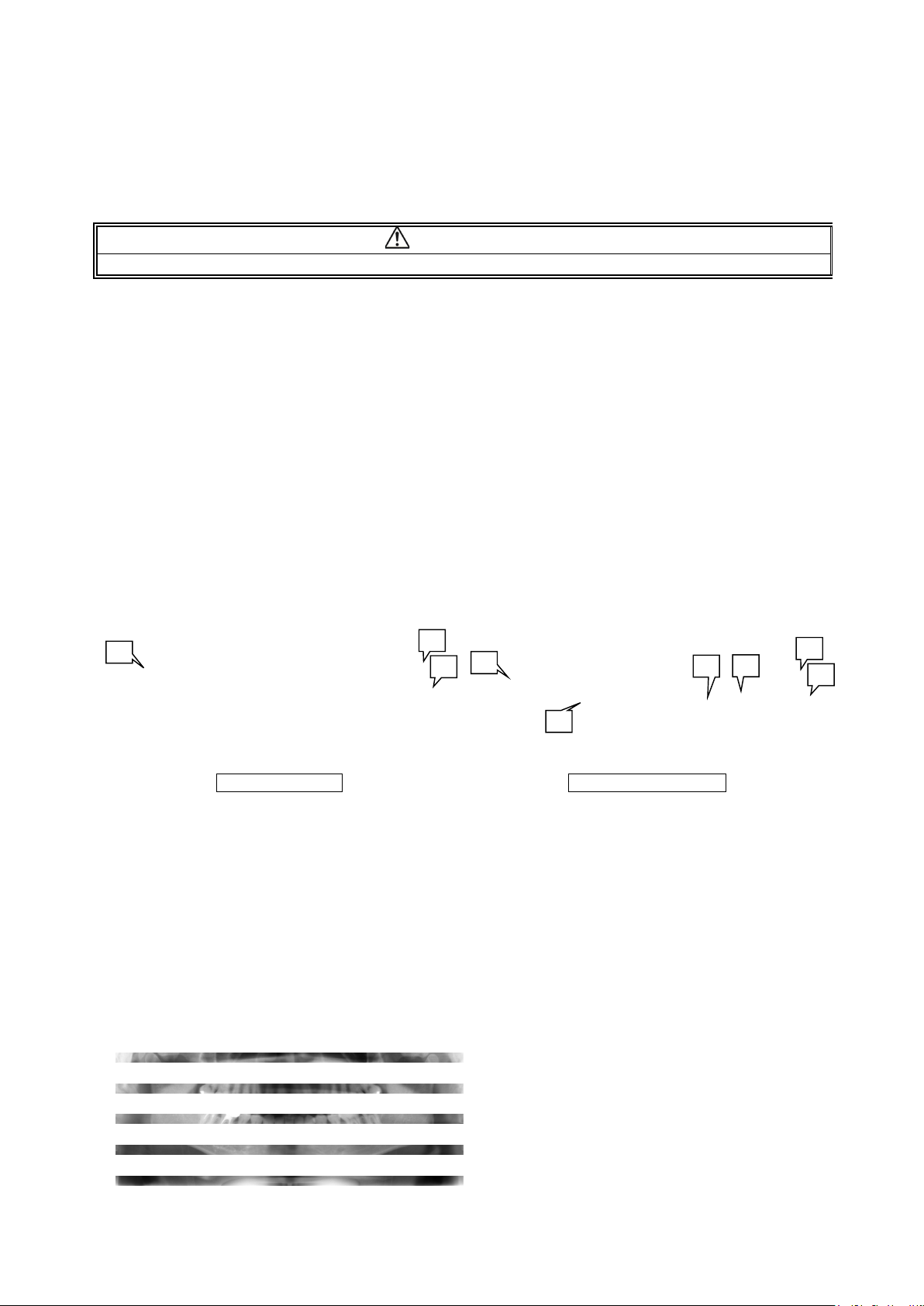
After the data transfer, the panoramic image is displayed for viewing.
When a tomosynthesis exposure is performed, the images of the optimum tomographic positions
for automatic saving is displayed.
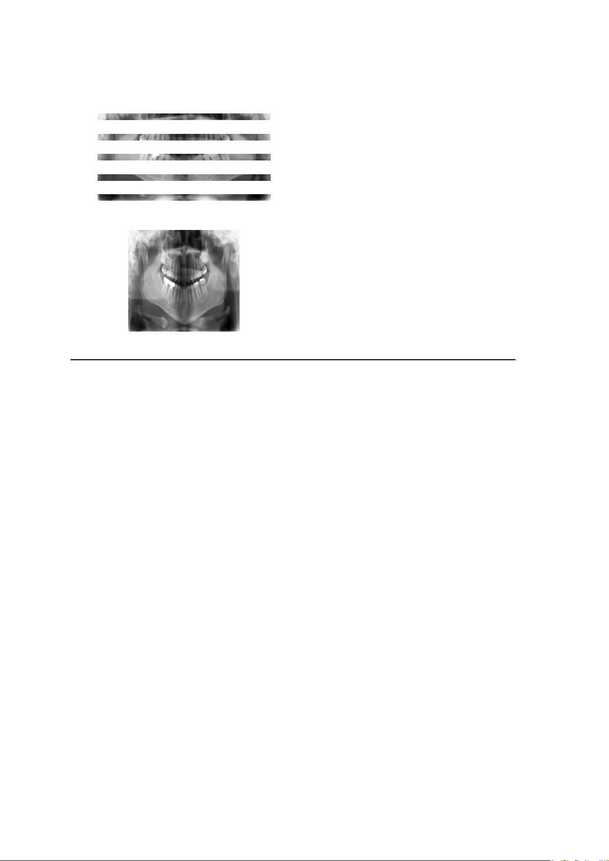
①
Panoramic display Tomosynthesis display
① [Scan mode] Displays the exposure conditions.
② [Save] Closes the window with the image saved.
③ [Close] Closes the window without the image saved.
④ [Slice position]
⑤ [Init position]
⑥ [Orbit settings]
By moving this slide bar the tomographic plane can be changed.
Moving to the right produces forward movement of the tomographic plane,
while moving to left produces backward movement.
Returns the value that was shown when the save screen is displayed.
After the panoramic radiograph is taken, construct a panoramic image by
setting the anterior section orbit and the molar section orbit. (refer to
6.6.2. Set tomosynthesis orbit)
When the slice position is set to +15:
②
①
④
11-14
②
Page 43
B02-T216E-A Bel-Cypher Pro
When the slice position is set to 0:
When the slice position is set to -15:
*Slide bar of tomosynthesis for changing range is different from radiography orbit (adults or children.)
11-15
Page 44

B02-T216E-A Bel-Cypher Pro
6.6.2. Tomosynthesis orbit setting
After the panoramic radiograph is taken, you can create a panoramic image by setting the anterior
section orbit and the molar section orbit. Use this function when the patient positioning is improper, or
when the patient’s dentition is too far displaced from the standard orbit.
Remarks
・This function is available only when you take a panoramic image by using the tomosynthesis mode.
・Position the patient correctly.
When the patient positioning is improper (beyond the limit of adjustment), you may not able to get the
better image though you use this function.
・The lower limit value of the slice position may change when the image is created by using the orbit
setting screen.
・Please confirm the image is acceptable before saving it.
Once the image is saved, you can’t change the orbit again.
・The image in the orbit setting screen is shown without the edge emphasis.
6.6.3..Preparation of the orbit settings
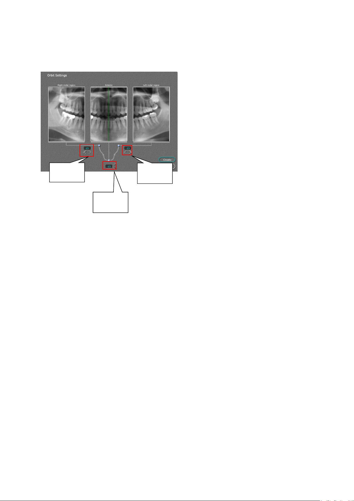
1. To use the tomosynthesis orbit setting, click
“Orbit set”
11-16
Page 45
B02-T216E-A Bel-Cypher Pro
button
6.6.4.Set the orbits
1.By using the Right/Left molar orbit adjust
button and anterior orbit adjust button, you
can change the slicing orbit plane.
Choose the orbit in which the anterior
section is clearly shown. Then adjust the
molar section so that the size of both left
molar and right molar become the same.
(Image changes in right/left directions)
・Right Molar:
By clicking the left button, the molar orbit
moves to cheek side (+) (Image expands to
right/left directions)
Right molar
orbit adjust
Left molar
orbit adjust
button
By clicking the right button, the molar
orbit moves to tongue side (-) (Image
shrinks toward the center)
Anterior
orbit adjust
button
・Left Molar:
By clicking the left button, the molar orbit
moves to tongue side (+) (Image expands
to right/left directions)
By clicking the right button, the molar
orbit moves to cheek side (-) (Image
shrinks toward the center)
・Anterior:
By clicking up button, the anterior orbit
moves to back side (-) (Image shrinks).
By clicking down button, the anterior orbit
moves to front side(+) (Image expands)
* Molar section and anterior section covers same teeth, the orbit change will be reflected in 6th and
7th tooth areas (molar) and 1st through 3rd area(anterior)
11-17
Page 46
B02-T216E-A Bel-Cypher Pro
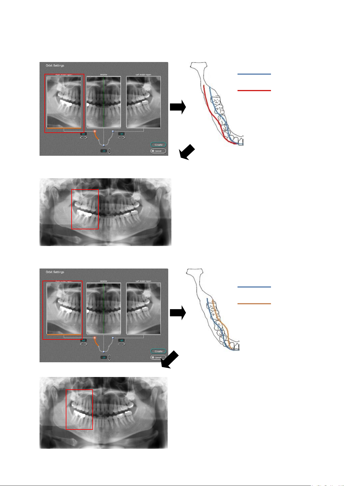
Example 1: Right molar +10
Orbit moves to cheek side for 10mm.
Example 2: Right molar -10
Orbit moves to tongue side for 10mm.
Standard
Orbit
+10mm
Standard
Orbit
-10mm
11-18
Page 47
B02-T216E-A Bel-Cypher Pro
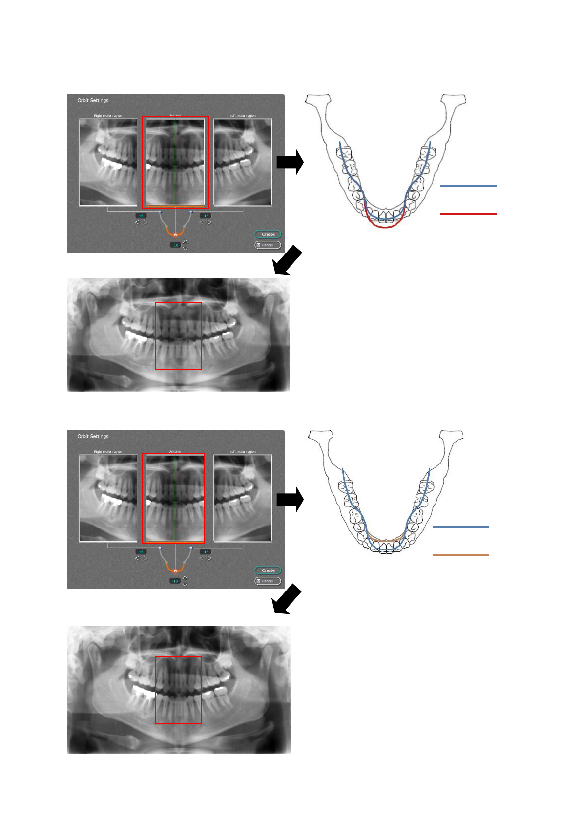
Example 3: Anterior +10
Orbit moves to front side for 10mm.
Example 4: Anterior -10
Orbit moves to back side for 10mm.
Standard
Orbit
+10mm
Standard
Orbit
-10mm
11-19
Page 48
B02-T216E-A Bel-Cypher Pro
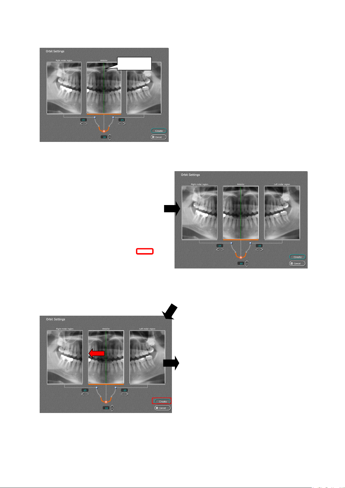
If the median plane is off, by dragging the median
Median
Plane
plane line, you can change the median plane.
*1: The median plane can be adjusted within
±10mm of median plane line.
*2: If the median plane is inclined by mispositioning of the patient, this function can’t
adjust the angle of the median plane.
Example 5:Move the Median Plane Line
* Below example shows that median plane line is off to the left side.
The median plane line is off to the left side
Click Orbit set
Move the median plane line (green) to the left
side to align the median plane line to the center
of image.
Click “Create” button.
Orbit setting screen is shown
Aligned median plane line is set to the center of
the image
11-20
Page 49
B02-T216E-A Bel-Cypher Pro
button
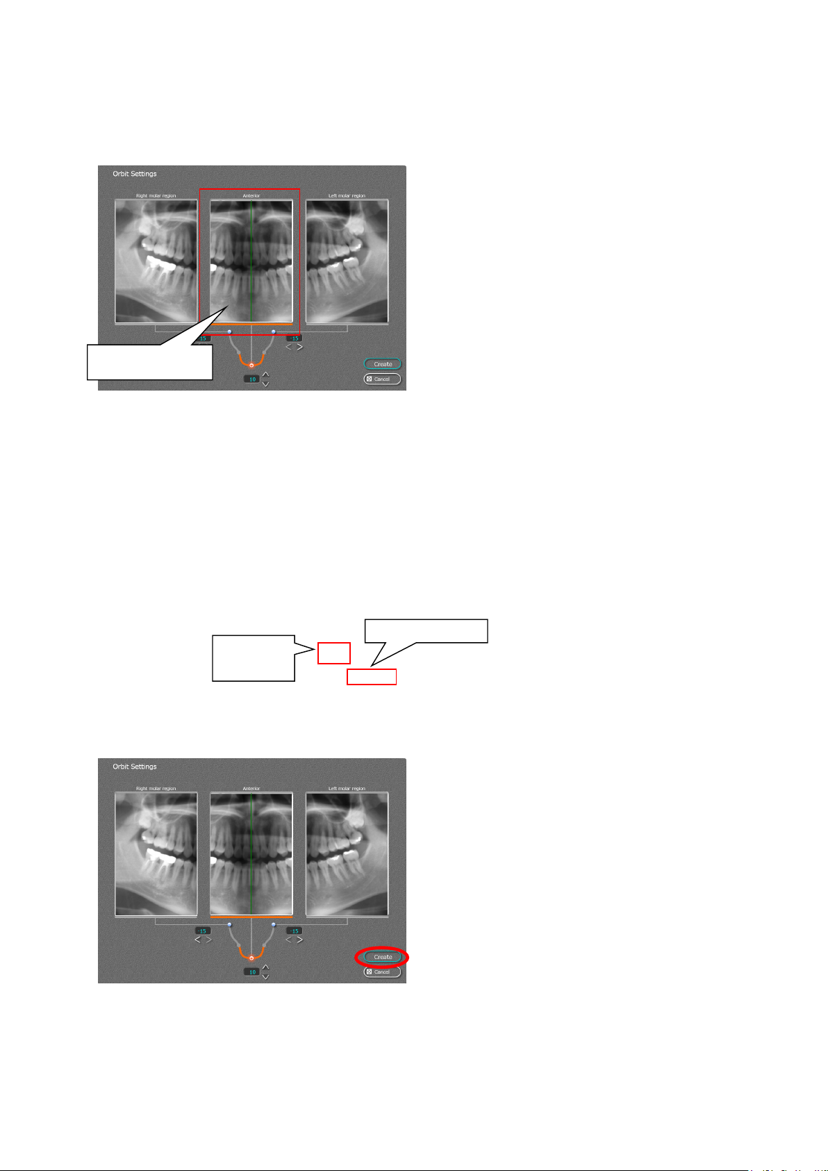
6.6.6.Anterior image enlarge function
* Use this function to align the median plane line by looking at the enlarged image.
Anterior section
image
Double click anterior section image.
Enlarged image is shown here.
Use the anterior orbit adjust button to change the
slicing orbit.
* Refer 6.6.4. .Set the orbits section.
Click “Change” button, to reflect adjusted slicing
orbit.
Adjusted image is displayed.
Change button
Anterior
orbit adjust
Create Image (reflect changes to the image)
Click “Create” button.
The image that reflects the orbit adjustment and
median line adjustment will be created.
After the image is created, screen comes back to
image save screen. Follow 6.6.9. procedure
to save the image.
11-21
Page 50
B02-T216E-A Bel-Cypher Pro
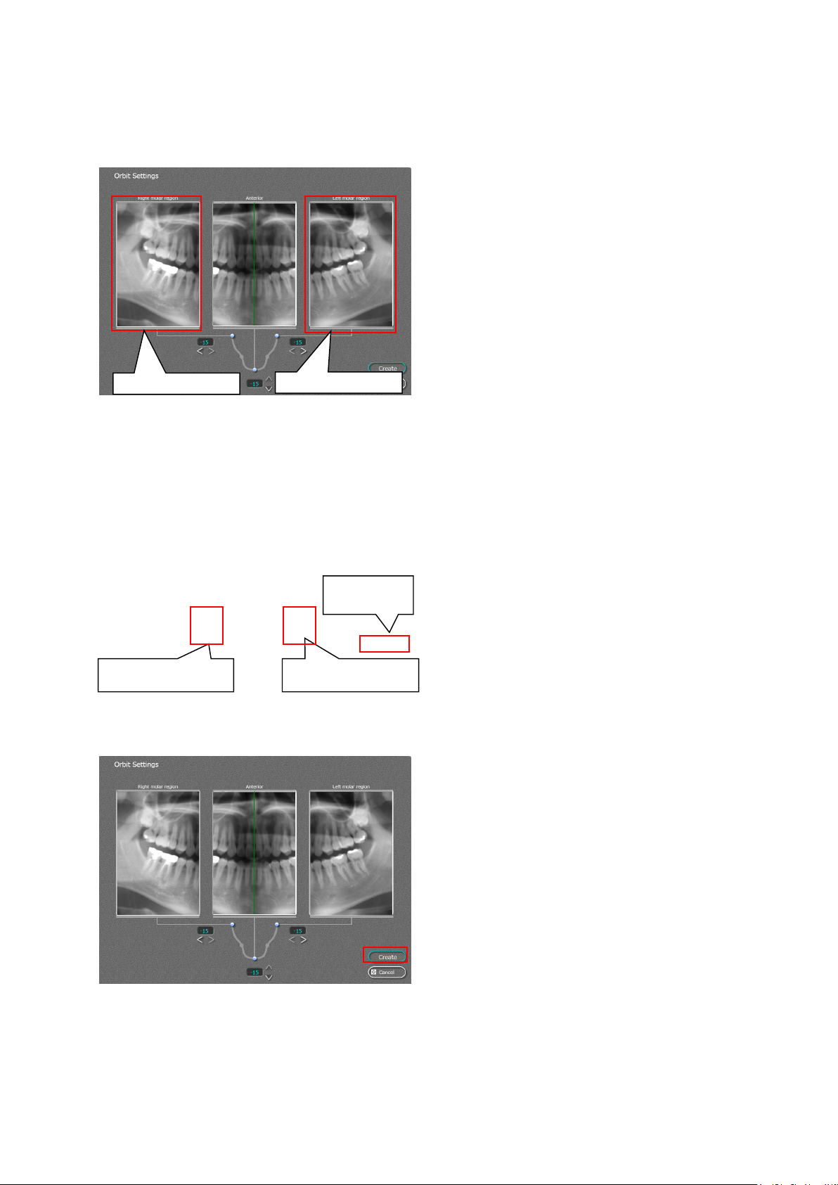
6.6.7. Molar image enlarge function
* Use this function to adjust the molar orbit line by looking at the enlarged image.
Double click either right or left molar section
screen.
Left molar section
Right molar orbit
adjustment button
6.6.8. Create Image
(reflect changes to the image)
Right molar section
Change
button
Left molar orbit
adjustment button
Enlarged image is shown.
Use molar orbit adjustment buttons to change
the orbit plane.
* Refer 6.6.4. .Set the orbits section.
Click “Change” button, to reflect adjusted slicing
orbit.
Adjusted image is displayed.
Click “Create” button.
An image that reflects the orbit adjustment and
median line adjustment will be created.
After the image is created, screen comes back to
image save screen. Follow 6.6.9. procedure to
save the image.
11-22
Page 51
B02-T216E-A Bel-Cypher Pro
②
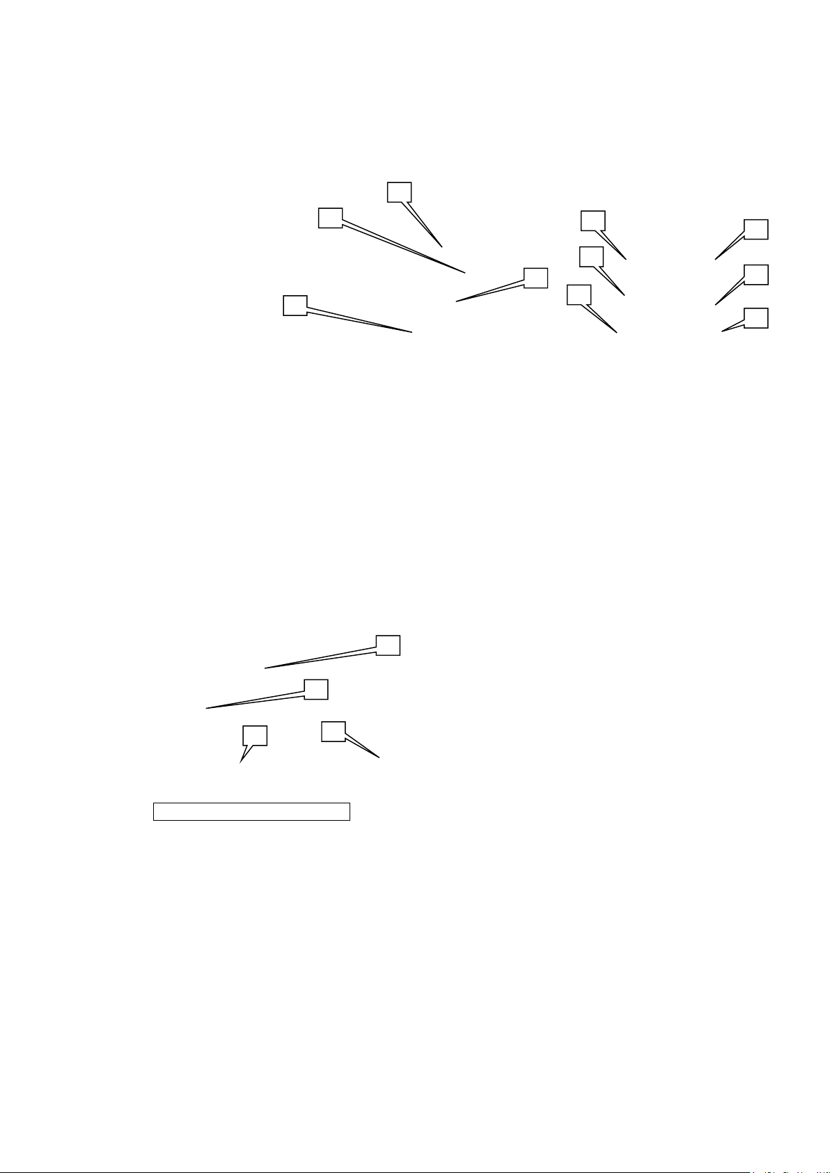
6.6.9. The image parameters can be edited in the image processing area.
The editable parameters are brightness, contrast, gamma, and edge emphasis.
① [Brightness]
② [Contrast]
③ [Gamma]
④ [Edge Emphasis]
⑤ [Reset]
⑥ [No Processing]
⑦ [Detail]
⑧ Zoom in/out
Moving the slide bar to the left darkens the image, and moving it to the right
brightens the image.
Moving the slide bar to the left increases image contrast, and moving it to the
right decreases contrast.
Moving the slide bar to the left lightens mid tones, and moving it to the right
darkens them.
Changes the emphasis of edges in the image (similar to image sharpening).
Returns the value changed to the initial value.
Cancels the image processing by changing the value to the default value.
Sets the diameter and the range of edge emphasis.
Changes the zooming rate of the image.
When the image is zoomed in, dragging the display position of the image can
change the rate.
⑨ Back
Returns the zoom setting of the image to its initial value.
④
①
⑤
⑥
③
⑦
⑧
⑧
⑨
①
②
③
④
Edge Emphasis(Detail) display
① [Radius]
② [Range]
Indicates the range to apply emphasis of outline. Small values emphasize the
outline only, and large values emphasize the entire image.
Indicates the brightness level of the border line of images. Large values emphasize
the border line clearly.
③ [Reset] Returns the diameter and the range changed to their initial values.
④ [Close] Closes the edge emphasis (Detail) screen.
6.7.Save the Image as needed.
11-23
Page 52
B02-T216E-A Bel-Cypher Pro
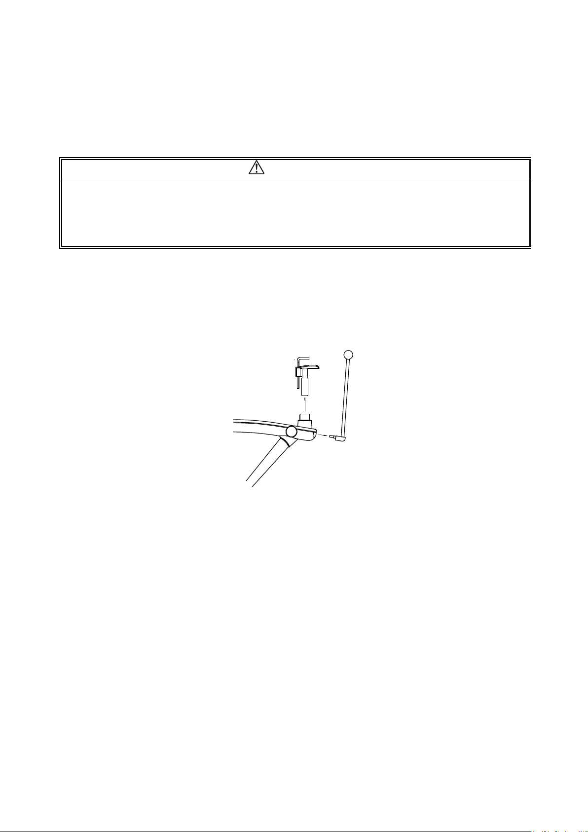
7.Cooling Time
7.1.When X-Ray Irradiation is complete, Bel-Cypher Pro automatically goes into its cooling phase.
Remaining cooling time is displayed on the screen.
CAUTION
1.X-ray exposures cannot be made during COOLING TIME.
2.All key operations except the Reset key are inoperable during COOLING TIME.
3.Do not turn the power OFF until the end of COOLING TIME.
4. When a thermal error occurs, wait for 20 minutes before making another X-ray exposure.
8.Release of Patient
8.1.Carefully open temporal supports then release the patient.
8.2.Remove the Chinrest and Temporal supports.
11-24
Page 53
B02-T216E-A Bel-Cypher Pro
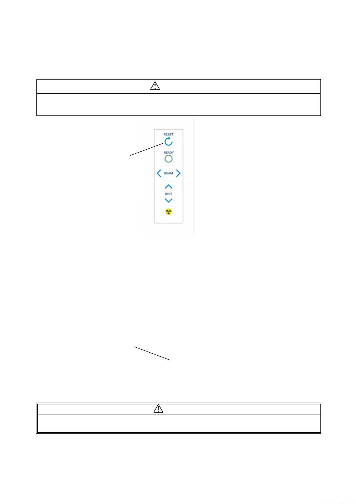
9.Bring Arm Unit to the Reset Position
By depressing the Reset key on the sliding unit, Arm Unit moves to Reset Position.
CAUTION
Before hitting the Reset Switch, remove the Chinrest and Temporal supports.
By hitting Reset Switch, Arm starts to rotate. Stay away from Rotation area to avoid injury.
Reset Switch
10.Turning Power OFF
10.1.Confirm cooling time is finished.
10.2.Confirm Panoramic Image is displayed on the PC Screen.
10.3.Depress “○” key on POWER switch to turn the power off.
Power Switch
At the Power-off mode, if you start TWAIN Program, “Communication Error” occurs.
If you don’t use Bel-Cypher Pro for more than 10 minutes, please turn off the power.
CAUTION
11-25
Page 54

B02-T216E-A Bel-Cypher Pro
12
12.Operation Procedure for TMJ
1. Preparation for exposure
1. 1.
*X-ray protective clothing
*Ear Rods for TMJ
2.Turn the Power of Bel-Cypher Pro
2. 1. Push “I“ on the power switch to turn the power ON.
3.Exposure settings
Start-up of imaging software
Start the imaging software from the management software.
12-1
Page 55
B02-T216E-A Bel-Cypher Pro
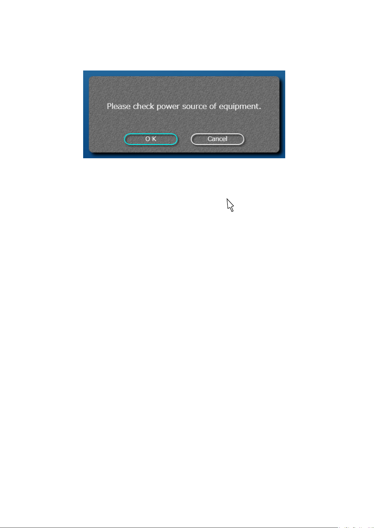
Check Power
If the equipment has already turned on, click OK.
RESET
Click "Reset" to return the equipment arm to its original position.
Choose TMJ Mode, selected mode will be highlighted.
12-2
Page 56
B02-T216E-A Bel-Cypher Pro
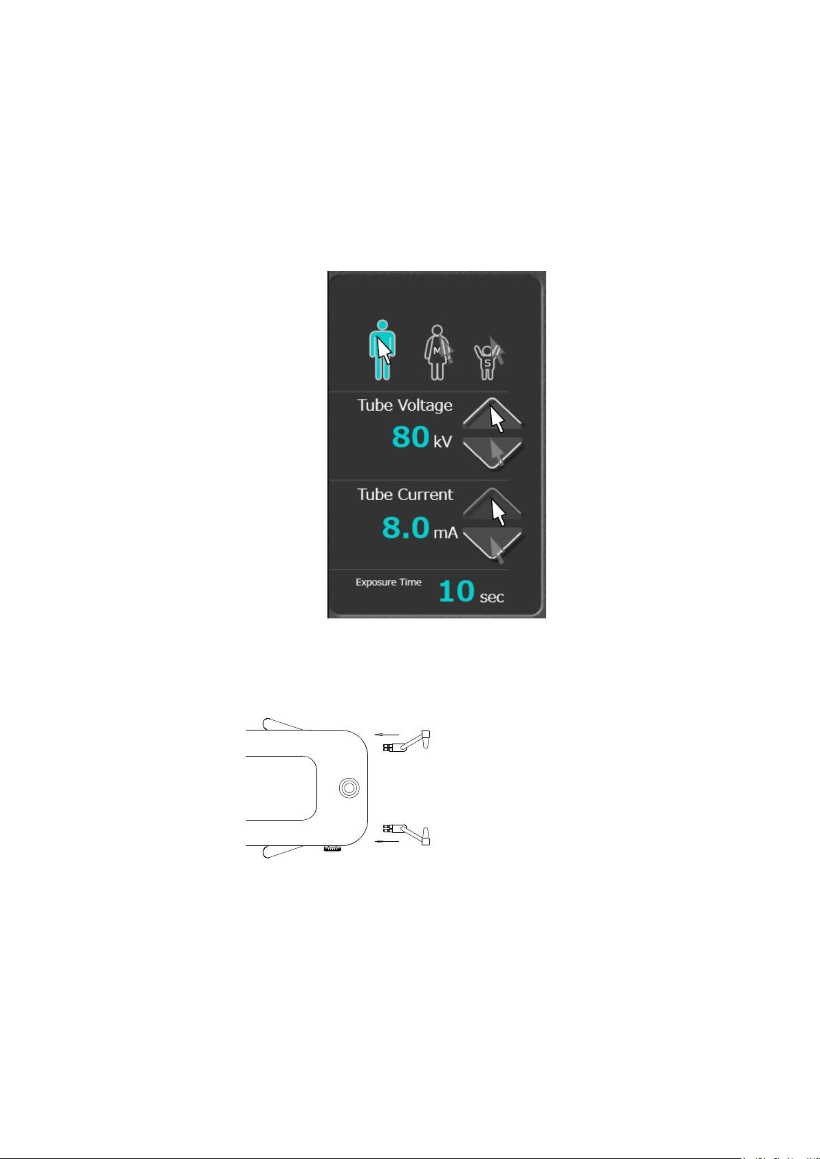
kV and mA settings
Refer Sec 13 Table of Exposure Settings to choose appropriate setting values.
- Discretionary setting
kV setting
Click the (UP) or (DOWN) symbols on the right side of the kV display.
mA setting
Click the (UP) or (DOWN) symbols on the right side of the mA display.
Or simply click patient size icon.
You may need to adjust mA / kV for some patients.
4. Patient Positioning
4. 1. Attach Ear Rods.
12-3
Page 57
B02-T216E-A Bel-Cypher Pro
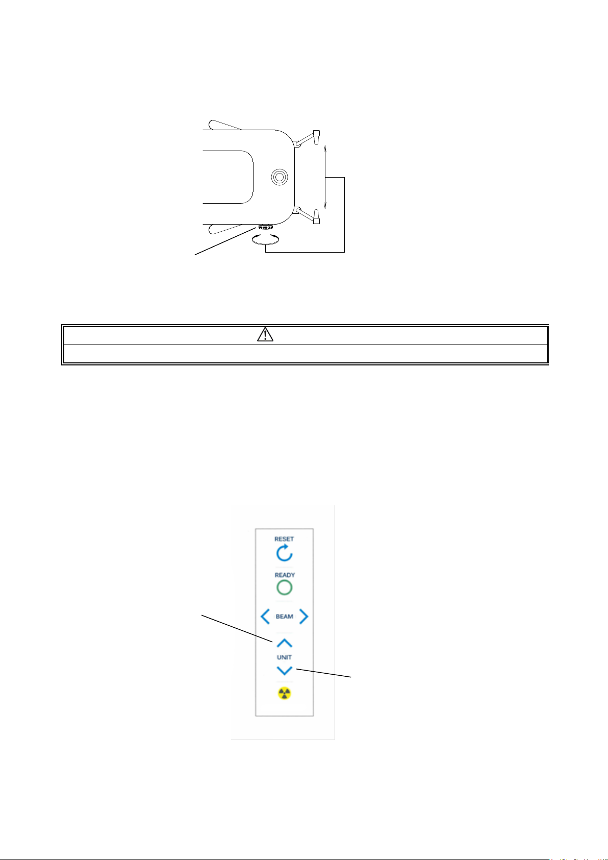
4. 2. By turning Adjuster Knob, open Ear Rods
4.3.Make patient wear X-ray protective clothing.
Adjuster Knob
CAUTION
Ensure that the patient and assistant are wearing X-ray protective clothing.
4.4.Bring the patient close to Bel-Cypher Pro.
4.5. Adjust the height of Chinrest by moving Sliding Unit Up/Down, so that the patient
can stand upright and align the ear rods to the patient’s external auditory foramen.
Sliding Unit Up
Sliding Unit Down
12-4
Page 58
B02-T216E-A Bel-Cypher Pro
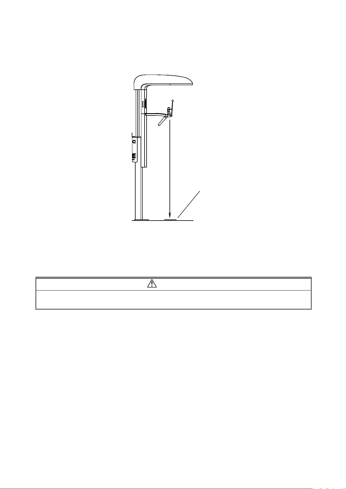
4.6.Bring patient to stand at the foot position as shown below.
4.7.Ask patient to hold the grips
4.8.Adjust the height of Chinrest by moving Sliding Unit Up/Down, align ear rods to
Foot Position
patient’s external auditory foramen.
CAUTION
While moving Sliding Unit, be careful that the Sliding Unit does not hit the patient’s head.
12-5
Page 59
B02-T216E-A Bel-Cypher Pro
a few
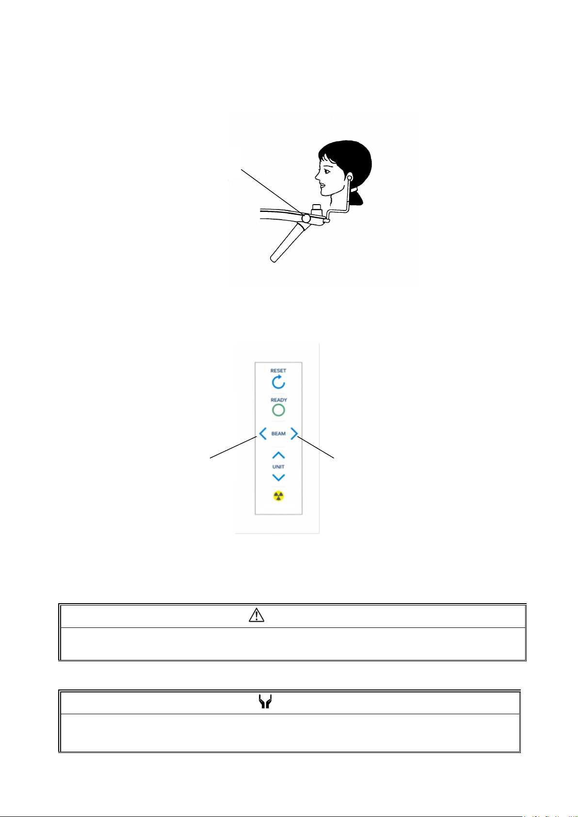
4. 9. Rotate the knob of the Rest Unit ASSY to insert Ear Rod into auricular holes of
the patient and lightly fix the positions of the Ear Rods.
Ear Rods
Adjuster Knob
4.10.Turn Focus Beams ON
Depress any either Focus Beam switch to turn Patient Focus Beams on.
4.11.Median Beam, Frankfurt Plane Beam & Focus Beam turn on at the same time.
Focus Beam Switch Focus Beam Switch
CAUTION
1. Warn patient not to look directly into the beam of the laser.
2. Do not set the beam into the patient’s eyes.
NOTE
Positioning beams have AUTO POWER OFF function. Laser beam will be automatically turned off
minutes after the beam is turn ON.
In order to turn the laser on again, depress either Focus Beam.
12-6
Page 60
B02-T216E-A Bel-Cypher Pro
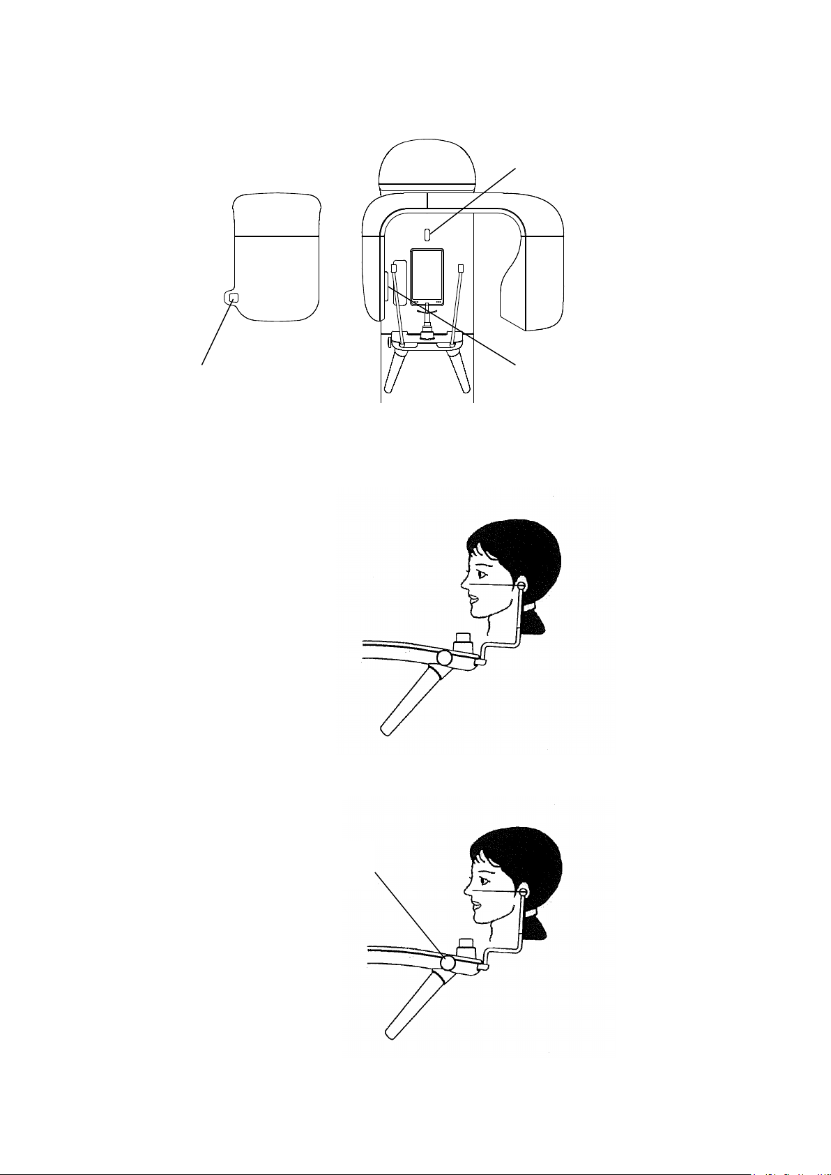
Focus Beam
4.12.Horizontally align to the patient’s naso-auricularplane
4.13.Rotate the knob of the Rest Unit ASSY to insert Ear Rod into auricular holes of
Median Beam
Frankfurt Plane Beam
the patient and lightly fix Ear Rod positions.
Ear Rods
Adjuster Knob
12-7
Page 61
B02-T216E-A Bel-Cypher Pro
. Operator must stand
will stop
Reset
5.Ready On
Please refer to 5 Ready On of the Panoramic Procedures
6.X-Ray Irradiation
WARNING
1.Other people except patient and operator should be outside of X-ray room.
2.The X-ray exposure switch should be depressed 7 feet away from Bel-Cypher Pro
behind the shielded partition.
3.Carefully observe patient while X-ray is irradiated, release an Exposure switch immediately
when any trouble happens.
4.Instruct patient not to move while X-ray is irradiated.
NOTE
1. The exposure switch is deadman type. X-ray irradiation and the movement of the Arm Unit
immediately when the exposure switch is released.
2. If exposure switch is released while an X-ray is in progress, release the patient and depress
switch to bring Arm Unit to the Reset position. Start from the beginning again.
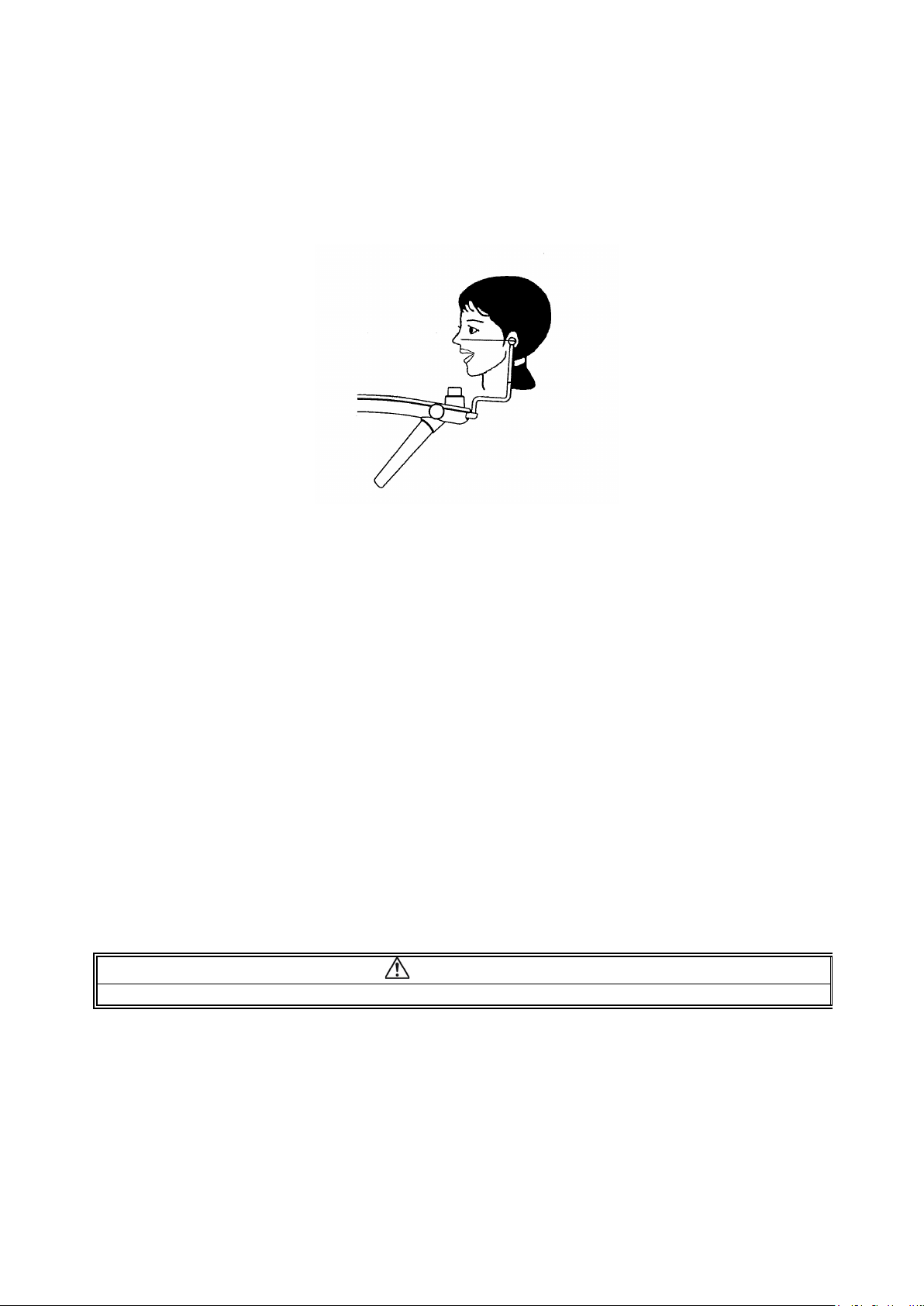
6.1.TMJ Lateral 4 sections consist of a series of two exposures. 1st exposure for the diagnosis of
TMJ with mouth closed and 2nd exposure for TMJ with mouth open.
6.2.Patient’s mouth must be closed
6.3.Depress the exposure switch and hold until the end of exposure
6.4.The Arm Unit starts to rotate, X-RAY is indicated on indicator, and buzzer starts to
sound intermittently.
12-8
Page 62
B02-T216E-A Bel-Cypher Pro
6.5. After the end of the first exposure, X-RAY indication display is turned OFF, the
audible warning stops, the Arm Unit stops rotating, then returns to the Reset Position
automatically
6.6.Ask patient to open mouth by lowering mandible
6.7.Depress “READY” key to get into READY ON condition
6.8.Depress exposure switch and hold until the end of exposure
6.9.The Arm Unit starts to rotate, X-RAY is indicated on indicator, and buzzer starts to
sound intermittently.
6.10.X-RAY keeps indicating and buzzer keeps sounding
6.11.After 2nd exposure is finished, X-RAY light will be OFF, and buzzer will stop sounding
and Arm Unit will stop rotating.
6.12.”Transferring Data” is displayed on the PC screen
CAUTION
While data is transferring, do not turn off the power of Bel-Cypher Pro, or else data will be lost.
6.13.After data is transferred, TMJ Images are displayed on the screen
6.14.Save Images as needed.
12-9
Page 63
B02-T216E-A Bel-Cypher Pro
7.Cooling Time
7.1.When X-Ray Irradiation is completed, Bel-Cypher Pro automatically goes into its cooling
phase.
Remaining cooling time is displayed on the screen.
CAUTION
1.X-ray exposures cannot be made during COOLING TIME.
2.All key operations except the Reset key are inoperable during COOLING TIME.
3.Do not turn the power OFF until the end of COOLING TIME.
8.Releasing the Patient
8.1.Carefully open Ear Rods then release the patient.
8.2.Remove the Chinrest and Temporal supports.
9.Bring Arm Unit to the Start Position
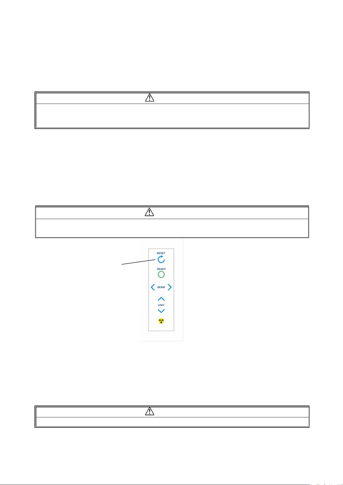
By depress Reset Switch on the Sliding Unit, Arm Unit moves to Reset Position.
CAUTION
Before hitting Reset Switch, remove Ear rods.
Stay away from Rotation area to avoid injury while Arm Unit is rotating.
Reset Switch
10.Turning Power OFF
10.1.Confirm cooling time is finished.
10.2.Confirm TMJ Images are displayed on the PC Screen.
10.3.Depress “○” key on POWER switch to turn the power off.
CAUTION
To prevent the risk of accident, turn the power switch off when the unit is not in use
12-10
Page 64
B02-T216E-A Bel-Cypher Pro
Tube Voltage
13
13.Table of Exposure Settings
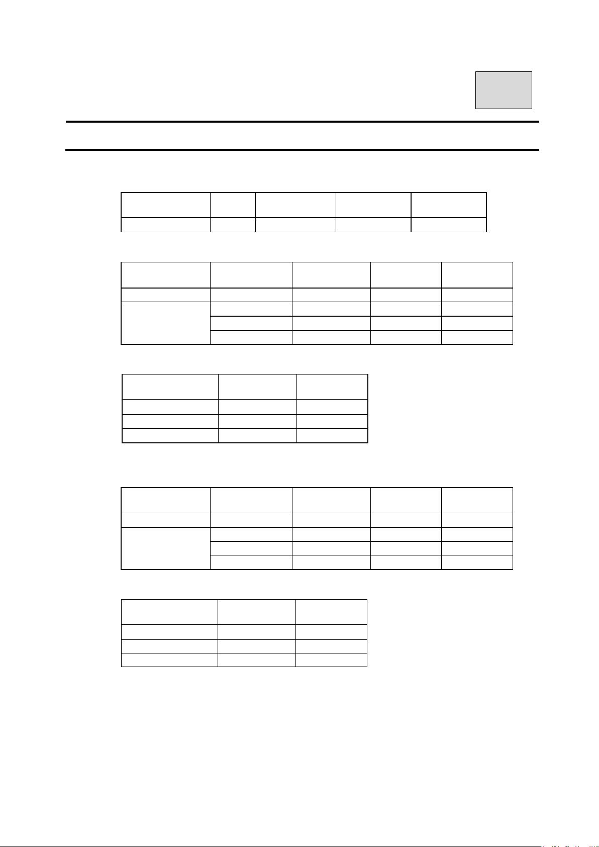
1. Panorama & Panoramic Bitewing
Panoramic Child : CHILD ORBIT (PANORAMA:S)
Age Sex
5~11years -
Panoramic Adult : ADULT ORBIT (PANORAMA:N)
Age Sex
12~15 years -
Female(small)
Adult
Factory default setting(Panoramic Adult)
S(Small)
M(Medium)
L(Large)
Male/Female 65~75 5~8
Male(Large)
Tube Voltage
(kV)
(kV)
60
Tube Voltage
Tube Current
66 5
68 5
70 5
2. TMJ
TMJ Lateral (4 sections)
Age Sex
5~15 years -
Female(Small)
Adult
Factory default setting(TMJ 4 sections)
S(Small)
M(Medium) 72 5
L(Large)
* Radiograph Condition depends on the age and bone density of the patient. Please select the
appropriate Tube Voltage and Tube Current by evaluating patients.
Male/Female
Male(Large)
Tube Voltage
(kV)
70 5
74 5
Tube Voltage
Tube Current
(mA)
Tube Current
(mA)
5~8
Tube Current
(kV)
60
60~70 5~8
68~80 5~8
(mA)
(kV)
60
60~70 5~8 2.5×4
65~75 5~8 2.5×4
68~80 5~8 2.5×4
(mA)
5~8
Tube Current
(mA)
5~8 2.5×4
Sec
10
Sec
10
10
10
10
Sec
13-1
Page 65
B02-T216E-A Bel-Cypher Pro
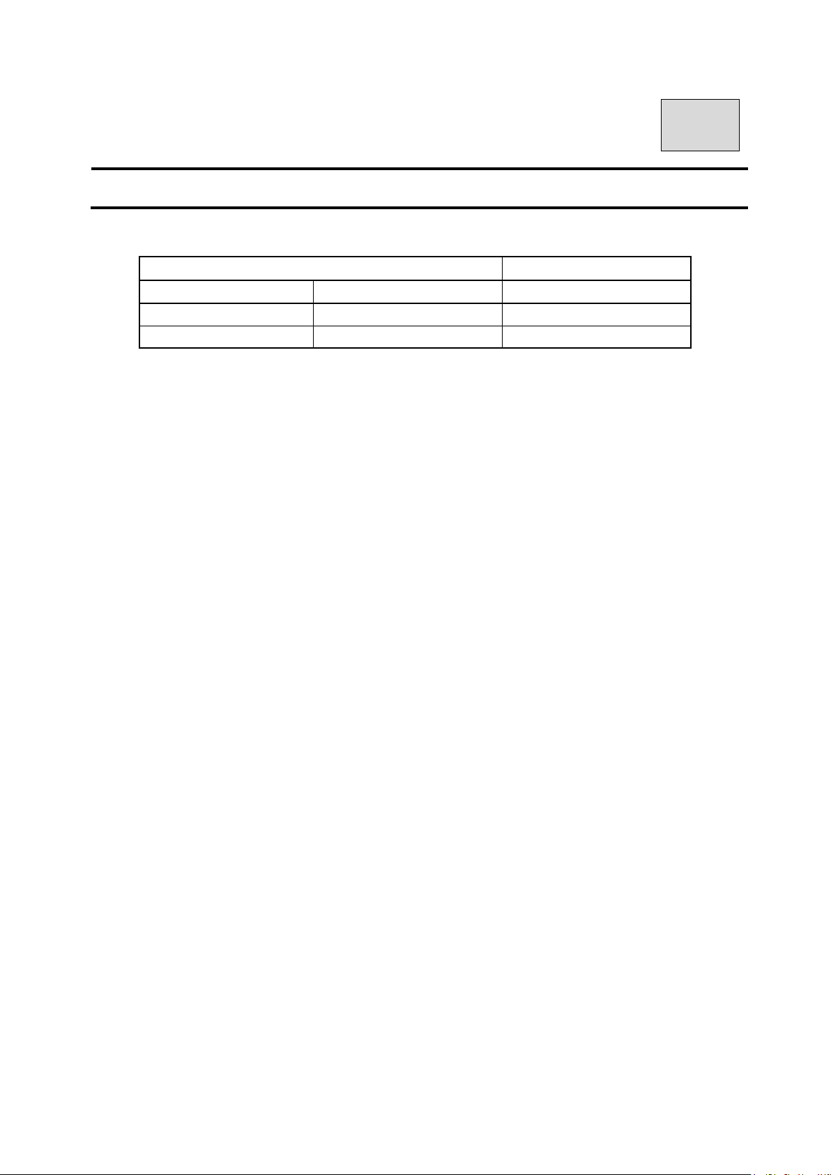
14
14.Magnification of Image
PANORAMA Child Orbit
PANORAMA Adult Orbit
TMJ Lateral 1.2
Radiographic Mode Magnification
1.2~1.3
1.2~1.3
14-1
Page 66
B02-T216E-A Bel-Cypher Pro
can be used as a reference, but the actual effective dose
15
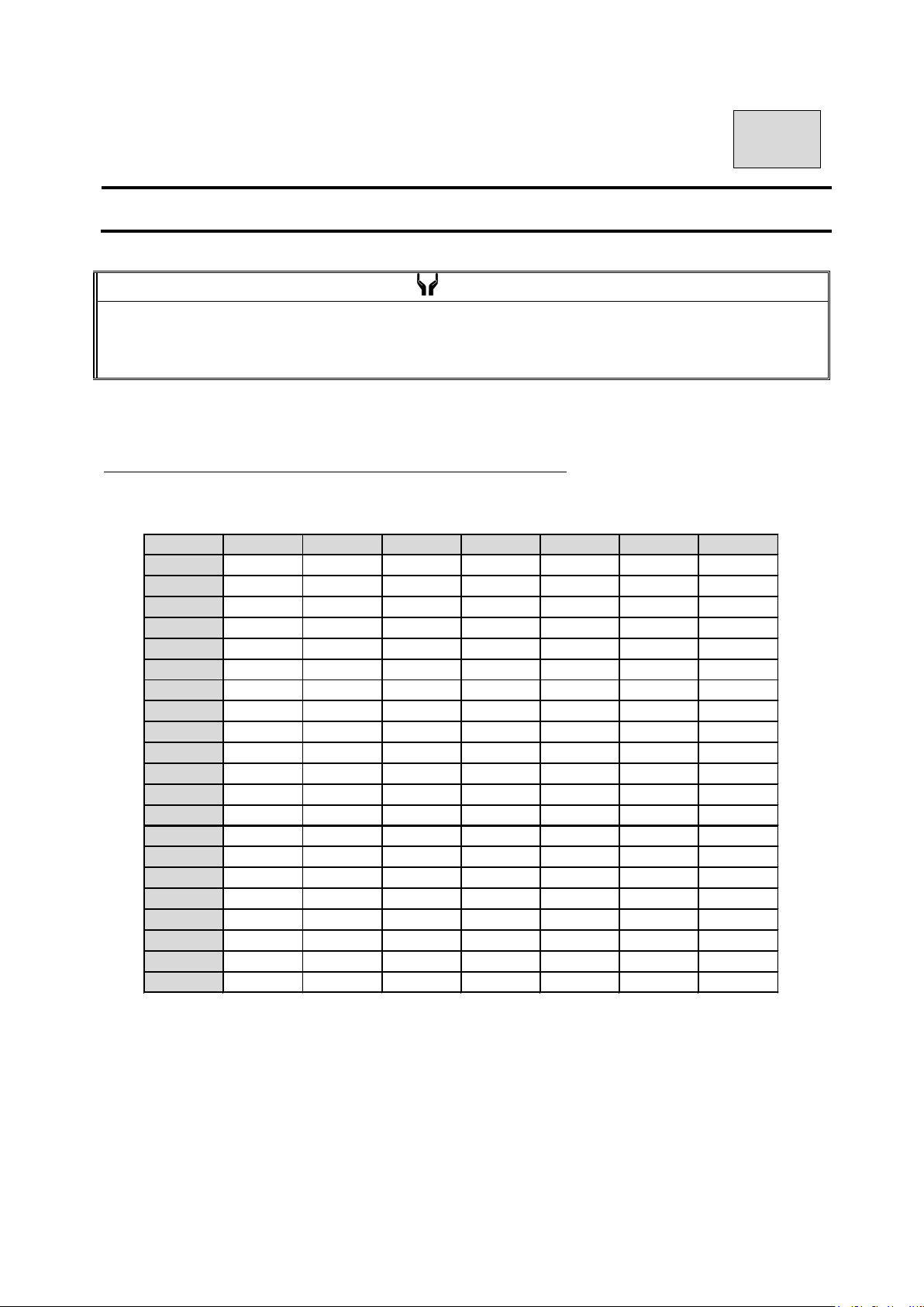
15.Dose information
NOTE
Excessive dose is a health hazard, pay attention not to exceed the radiation dose necessary for diagnosis.
Dose Area Product values on following tables
depends on the body type, the age of the patient, the position of the patient, etc.
Each AIR KERMA value and DAP value of following tables has 50% overall uncertainty.
The integrated value of AIR KERMA in front of the x-ray detector
Panorama 10sec / TMJ 2.5sec×4 Unit: mGy
KV\mA 2 3 4 5 6 7 8
60 1.16 1.77 2.41 2.94 3.55 4.12 4.66
61 1.21 1.84 2.43 3.07 3.64 4.29 4.85
62 1.26 1.92 2.53 3.19 3.79 4.47 5.05
63 1.31 1.99 2.63 3.32 3.94 4.65 5.26
64 1.37 2.07 2.73 3.46 4.10 4.84 5.47
65 1.42 2.15 2.84 3.59 4.26 5.03 5.68
66 1.47 2.24 2.95 3.73 4.42 5.22 5.90
67 1.53 2.32 3.06 3.87 4.59 5.41 6.12
68 1.59 2.41 3.17 4.01 4.76 5.61 6.34
69 1.64 2.49 3.29 4.15 4.93 5.81 6.57
70 1.70 2.58 3.40 4.30 5.10 6.02 6.80
71 1.76 2.67 3.52 4.45 5.28 6.23 7.04
72 1.82 2.76 3.64 4.60 5.46 6.44 7.28
73 1.88 2.85 3.76 4.76 5.64 6.66 7.52
74 1.94 2.95 3.89 4.91 5.83 6.88 7.77
75 2.01 3.04 4.01 5.07 6.02 7.10 8.03
76 2.07 3.14 4.14 5.23 6.21 7.33 8.28
77 2.14 3.24 4.27 5.40 6.41 7.56 8.54
78 2.20 3.34 4.40 5.56 6.60 7.79 8.80
79 2.27 3.44 4.54 5.73 6.80 8.03 9.07
80 2.34 3.54 4.67 5.91 7.01 8.27 9.34
15-1
Page 67
B02-T216E-A Bel-Cypher Pro
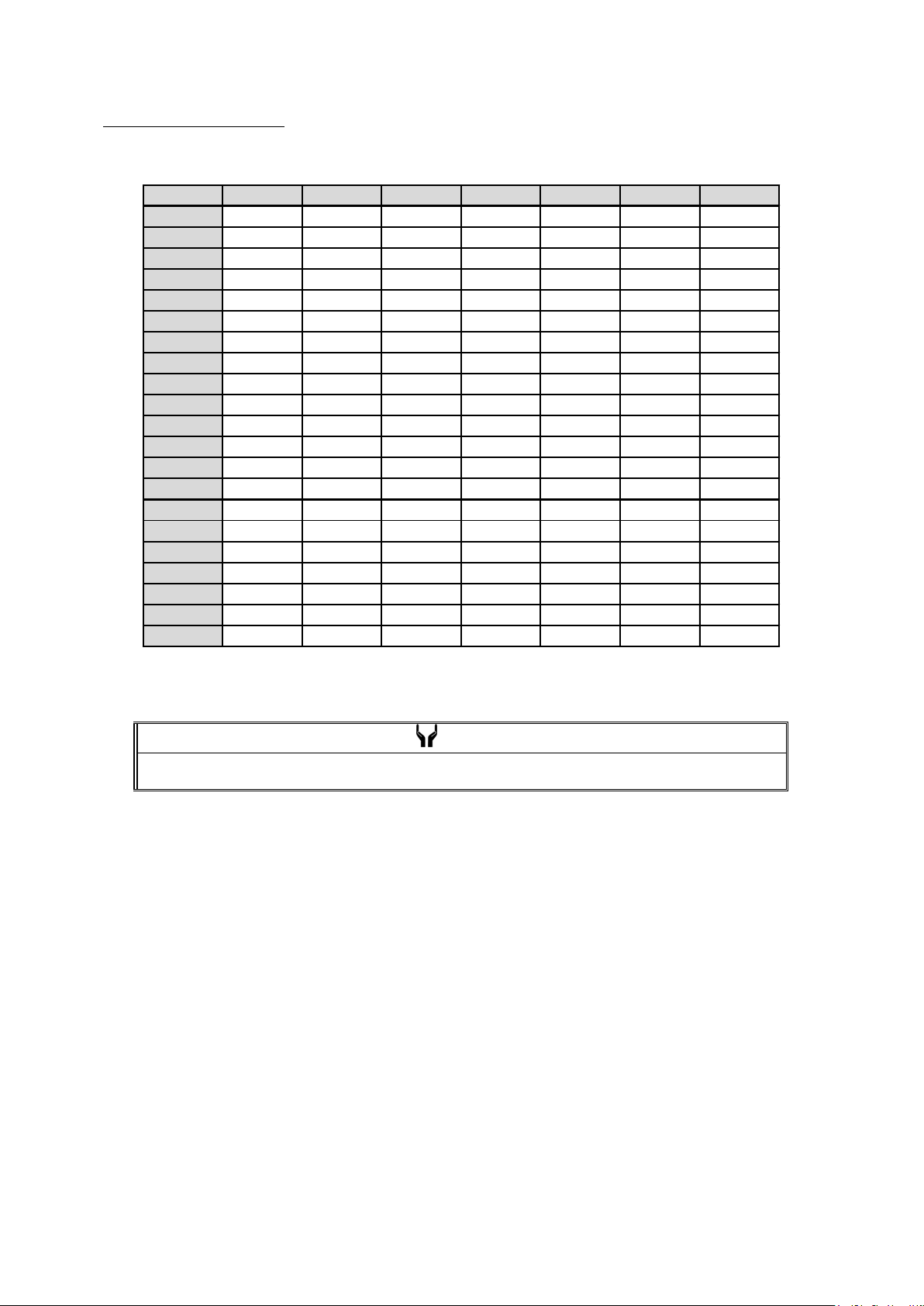
Dose Area Product (DAP)
Panorama 10sec / TMJ 2.5sec×4 Unit: mGycm
KV\mA 2 3 4 5 6 7 8
60 9.58 14.53 19.83 24.22 29.26 33.91 38.36
61 9.99 15.15 19.98 25.25 29.96 35.35 39.95
62 10.40 15.78 20.80 26.29 31.20 36.81 41.61
63 10.82 16.42 21.65 27.36 32.47 38.31 43.29
64 11.25 17.07 22.51 28.45 33.76 39.83 45.01
65 11.69 17.73 23.38 29.56 35.07 41.38 46.77
66 12.14 18.41 24.28 30.68 36.41 42.96 48.55
67 12.59 19.10 25.18 31.83 37.78 44.56 50.37
68 13.05 19.80 26.11 33.00 39.16 46.20 52.22
69 13.52 20.51 27.05 34.19 40.57 47.86 54.10
70 14.00 21.24 28.01 35.40 42.01 49.56 56.01
71 14.49 21.98 28.98 36.63 43.47 51.28 57.96
72 14.98 22.73 29.97 37.88 44.95 53.03 59.93
73 15.49 23.49 30.97 39.15 46.46 54.81 61.94
74 16.00 24.26 31.99 40.44 47.99 56.61 63.99
75 16.52 25.05 33.03 41.75 49.55 58.45 66.06
76 17.04 25.85 34.08 43.08 51.13 60.31 68.17
77 17.58 26.66 35.15 44.43 52.73 62.21 70.31
78 18.12 27.48 36.24 45.81 54.36 64.13 72.48
79 18.67 28.32 37.34 47.20 56.01 66.08 74.68
80 19.23 29.17 38.46 48.61 57.69 68.06 76.92
2
NOTE
DAP value is calculated by multiplying Exposure Field to the AIR KERMA value.
15-2
Page 68
B02-T216E-A Bel-Cypher Pro
16
16.Daily maintenance
Cleaning and Disinfection
In order to ensure proper hygiene and cleaning of the equipment, the following procedure must be followed.
1. Always disconnect the unit from the mains supply before cleaning or disinfection. No water or any other
liquids should be allowed to enter the equipment, as this can cause short-circuits and corrosion.
2. The unit, including accessories and connecting cables, should be cleaned or disinfected only by using a
damp cloth, followed by rubbing down with a dry cloth. Do not use solvents (toluene, benzine, etc.),
corrosive cleaning agents or abrasive polishing materials. Spray disinfectants are not recommended, as
the disinfectants may penetrate into the unit and cause short circuits or corrosion.
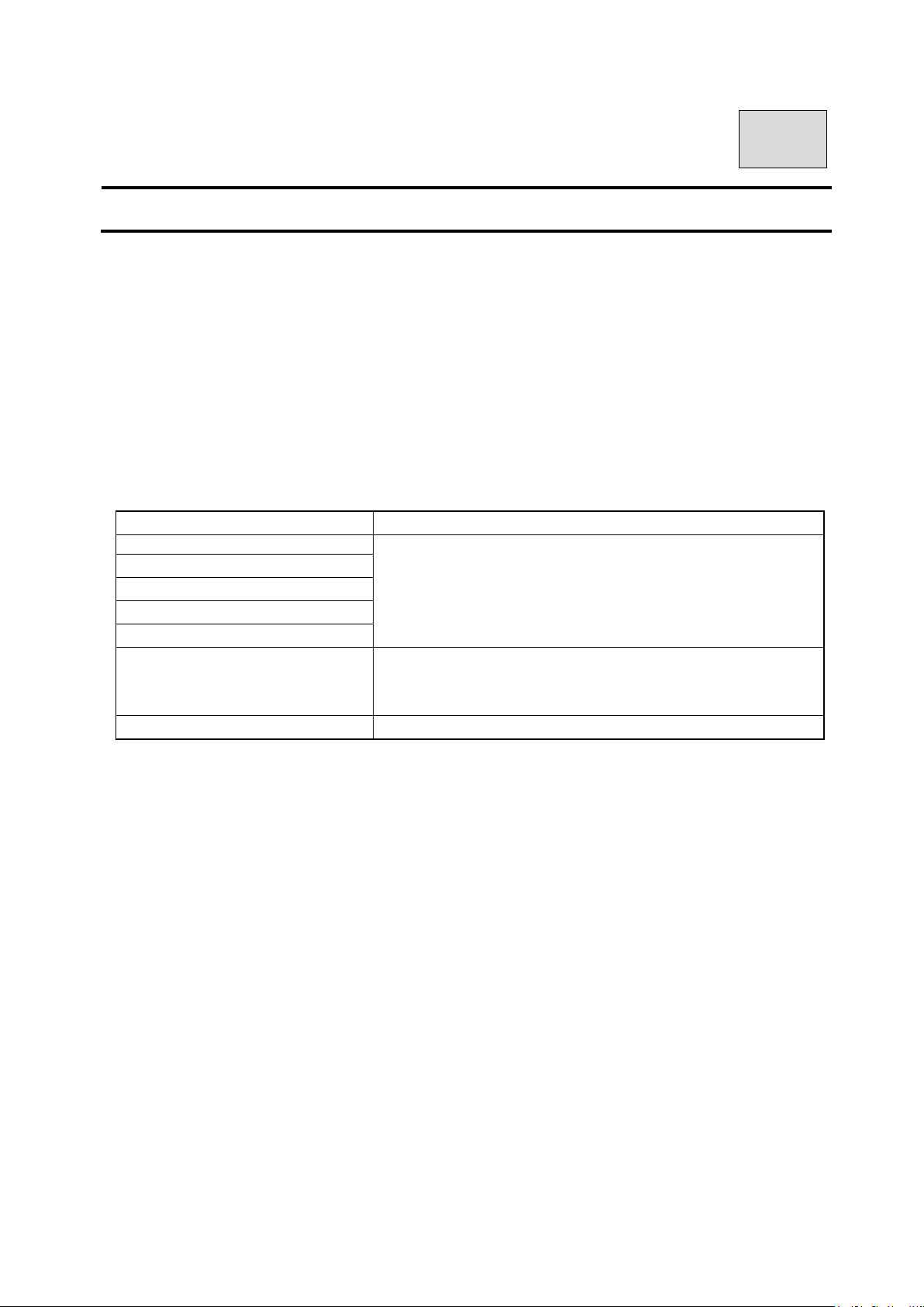
3. For parts specified in the table below, please clean or disinfect according to the instructions in the table.
Parts How to maintenance
Bite Blocks (For Panorama)
Temporal supports
Ear Rods (TMJ Lateral 4 sections)
Chinrest (Panorama)
All other parts which patients touch.
All other parts which operator touch.
Outside cover of the equipment
Make enough disinfectant with alcohol for medical use, of which
alcohol should be over 76% by volume. after every individual pa
tient session
Make enough disinfectant with alcohol for medical use, of which
alcohol should be over 76% by volume, at end of daily operatio
n.
Wipe equipment with a dry cloth at the end of daily operation.
16-1
Page 69
B02-T216E-A Bel-Cypher Pro
Check
Treatment
Check
Treatment
for
20
17
17.Trouble Shooting
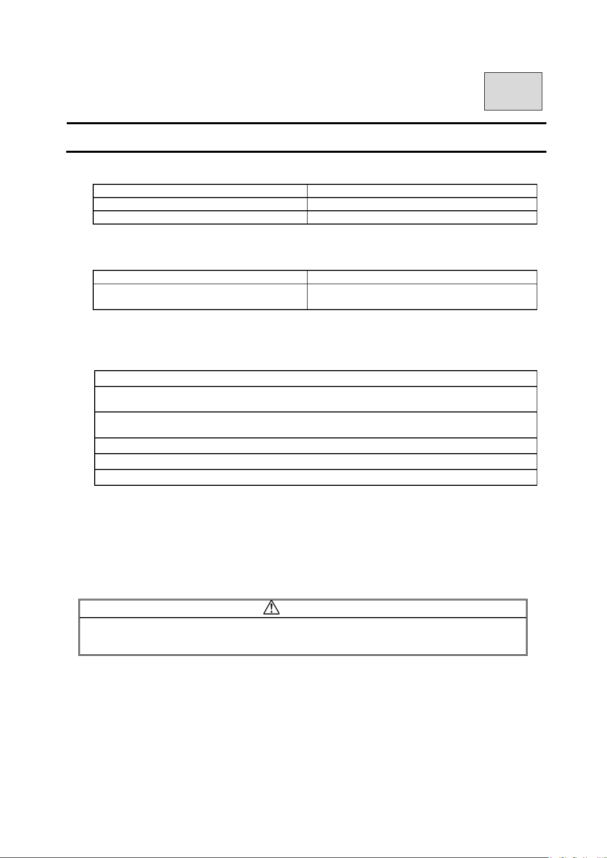
1.POWER can not be turned ON
Is breaker turned on? Turn breaker on.
Is power plug connected to outlet? Connect power plug.
2.READY can not be turned on
Is positioning of Arm Unit at the Reset
Position?
3.Error message on PC display
Treat by following messages on display.
Invertor error. Depress RESET button. Turn off the power and wait for 20 minutes
cooling.
X-Ray Tube temperature error. Depress RESET button. Turn off the power and wait for
minutes for cooling.
Y-axis motor error. Depress RESET button.
Rotation motor error. Depress RESET button.
X-ray SW error. Depressing exposure switch may be too fast after READY ON.
Depress RESET key.
Display
If you can not solve problem by the above, turn off the power and turn on again.
* When the trouble cannot be resolved, turn the power of the equipment OFF, and unplug the
power cable from electric outlet, and contact your dealer or our office.
CAUTION
If you run software that force heavy load to PC, transfer & acquisition of image could be
interrupted.
17-1
Page 70
B02-T216E-A Bel-Cypher Pro
18
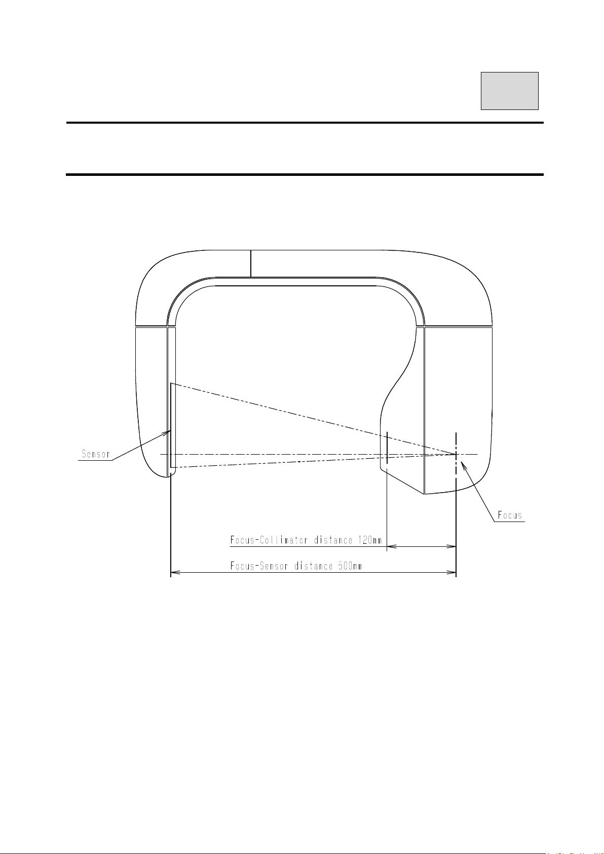
18.X-Ray Tube Focus, Sensor Location,
Collimator & Exposure Field
X-Ray Tube Focus and Sensor Location
18-1
Page 71
B02-T216E-A Bel-Cypher Pro
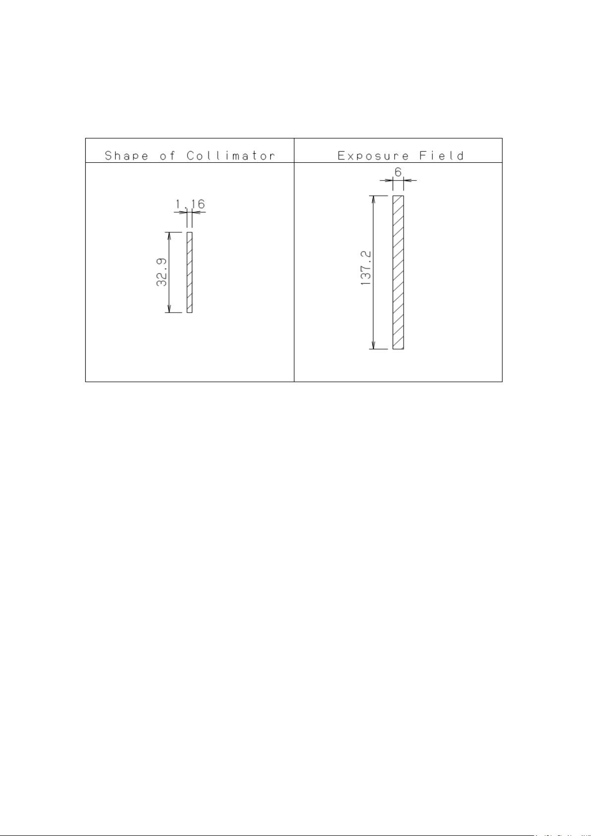
Collimator and Exposure Field
18-2
Page 72
B02-T216E-A Bel-Cypher Pro
NOTE
tient is most
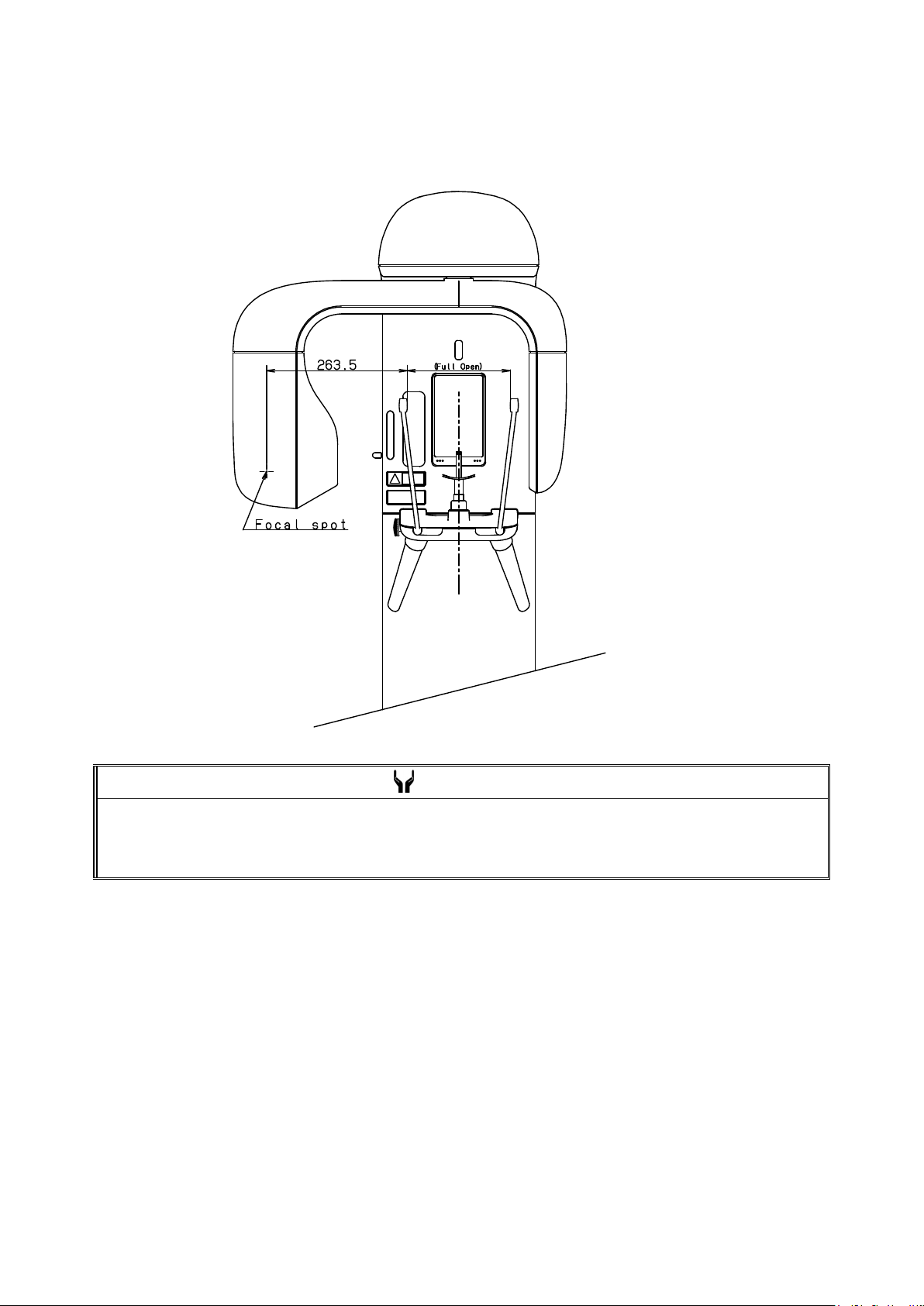
Focal spot to skin distance
The focal spot to skin distance depends on the size of the patient’s head.
On the use of this equipment, the patient position is specified, so appropriate positioning of the pa
important.
18-3
Page 73
B02-T216E-A Bel-Cypher Pro
19
19.Physical Dimensions
Dimensions of equipment
19-1
Page 74

B02-T216E-A Bel-Cypher Pro
20
20.Labels
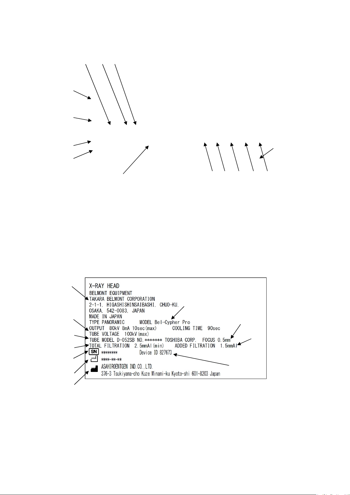
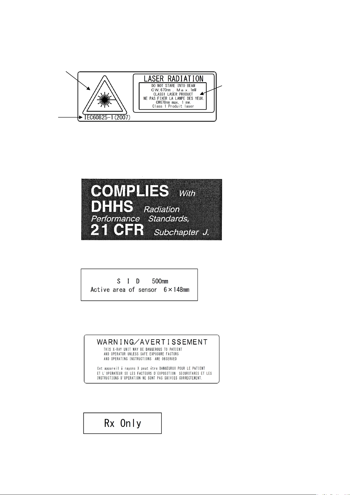
Description of labels
A X-RAY CONTROLLER LABEL
B X-RAY HEAD LABEL
C Warning Label (Laser)
D Certification Label of CFR 21
E Tubes Label
F Warning Label (UL)
G Rx Only Label
20-1
Page 75
B02-T216E-A Bel-Cypher Pro
A. X-RAY CONTROLLER LABEL
B. X-RAY HEAD LABEL
1: Indication of Distributor 6: Added Filtration
2: Model Name 7: Focus Size
USA : Bel-Cypher Pro 8: Serial Number
CANADA : Bel-Cypher Pro –H X199 9: Manufacturing Date
3: Maximum X-ray TUBE VOLTAGE 10: Manufacturer
4: X-RAY TUBE Type 11: Device ID (CANADA ONLY)
5: Total Filtration
⑧ ⑨ ⑩
①
②
⑪
⑫
1: Indication of Distributor 7: WEEE mark
2: Model Name 8: Source Voltage
USA : Bel-Cypher Pro 9: Power consumption
CANADA : Bel-Cypher Pro –C X199 10: Supply frequency
3: “Operation manual” mark 11: Serial number
4: “CAUTION label” mark 12: Date manufactured
5: “Ionizing Radiation” mark 13: UDI Barcode (USA ONLY)
6: TYPE B Applied Part 14: Device ID (CANADA ONLY)
①
③
④
⑤
⑧
⑨
⑩
⑭
⑬
③ ④ ⑤ ⑥ ⑦
②
⑦
⑥
⑪
20-2
Page 76
B02-T216E-A Bel-Cypher Pro
C. Warning Label (Laser)
1: Hazard Symbol
2: Explanatory Document
3: IEC standard
①
③
D. Certification Label of CFR 21
E. Tubes Label
F. Warning Label (UL)
G. Rx Only Label
②
20-3
Page 77

B02-T216E-A Bel-Cypher Pro
21
21.Technical Data
1. International standards
IEC 60601-1:2005
IEC 60601-1-2:2007
IEC 60601-1-3:2008
IEC 60601-2-63:2012
IEC 60601-2-28:2010
2. Equipment classification
1.According to the type of protection against electric shock
a) Equipment energized from external electrical power source.
Class I equipment
2.According to the degree of protection against electric shock
Type B applied part
Protection against Ingress of water
Ordinary4.
Equipment not suitable for use in the presence of a FLAMMABLE ANAESTHETIC MIXTURE
WITH AIR OR WITH OXYGEN OR NITROUS OXIDE
3.According to the mode of operation:
Continuous Operation
3. Environment condition
Temperature: 5-35°C
Humidity: 30-85%
Atmospheric pressure: 700-1060 hPa
4. Storage condition
Temperature: -10-60°C
Humidity: 10-95%
Atmospheric pressure: 700-1060 hPa
5. X-ray generator data
1. Maximum electric output
Maximum tube voltage: 80 kV
Maximum tube current: 8 mA
2. Nominal maximum electric power output
80 kV, 8 mA
640 W
3. Maximum product of current and time
80 mAs (8 mA,10 sec)
4. Minimum product of current and time
20 mAs (2 mA, 2.5 sec x 4 exposures)
5. Nominal anode input capacity
21-1
Page 78

B02-T216E-A Bel-Cypher Pro
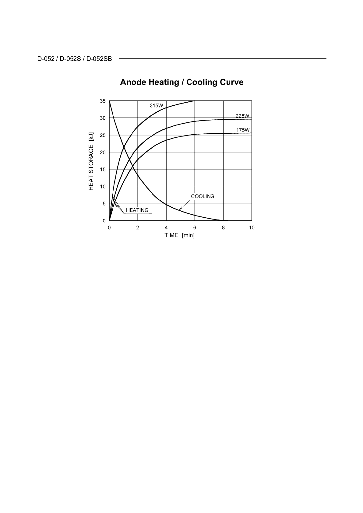
1750 W
6. Maximum anode heat capacity
35 kJ (50 kHU)
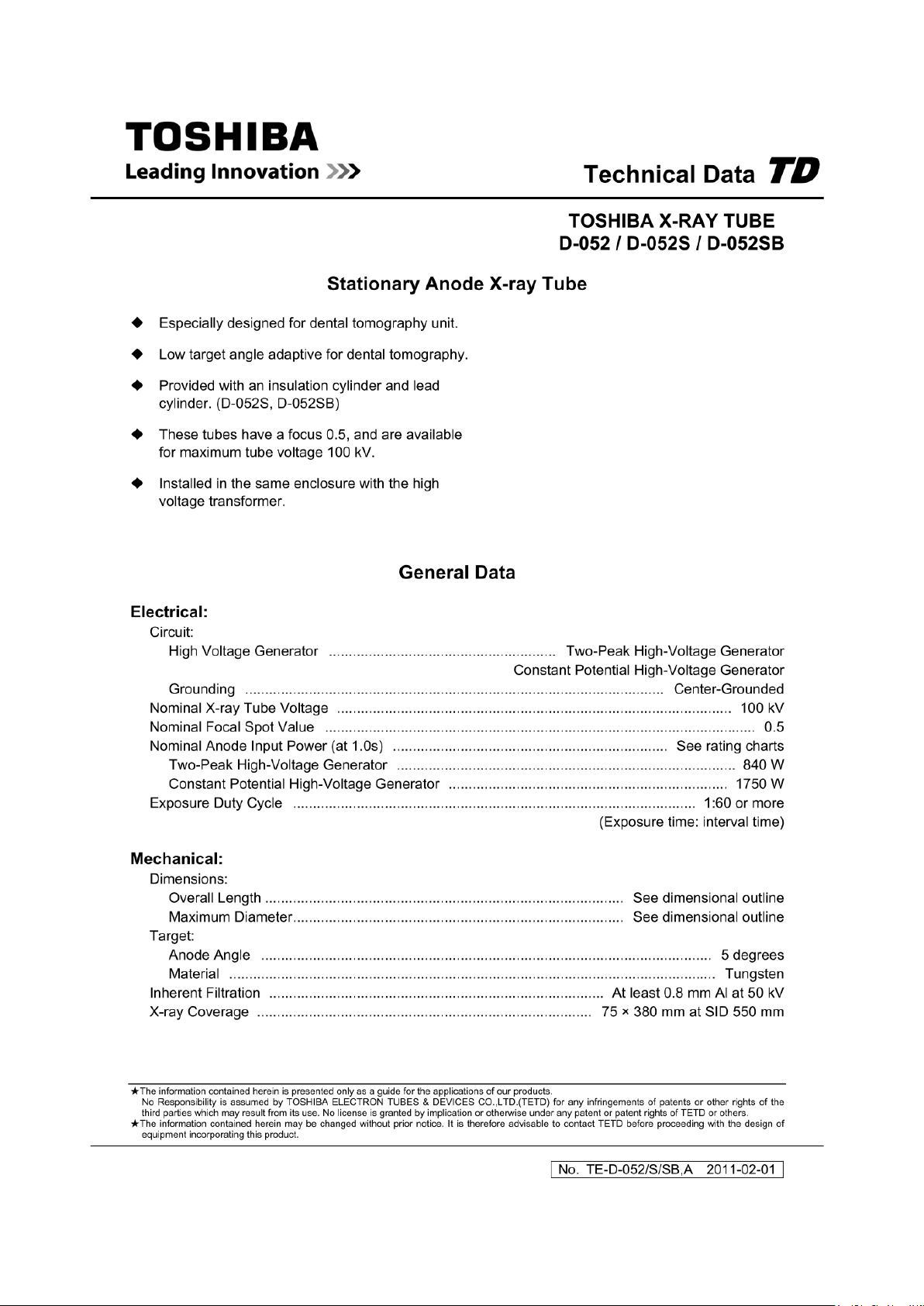
7. Target material
Tungsten (W)
8. Target angle (anode inclination)
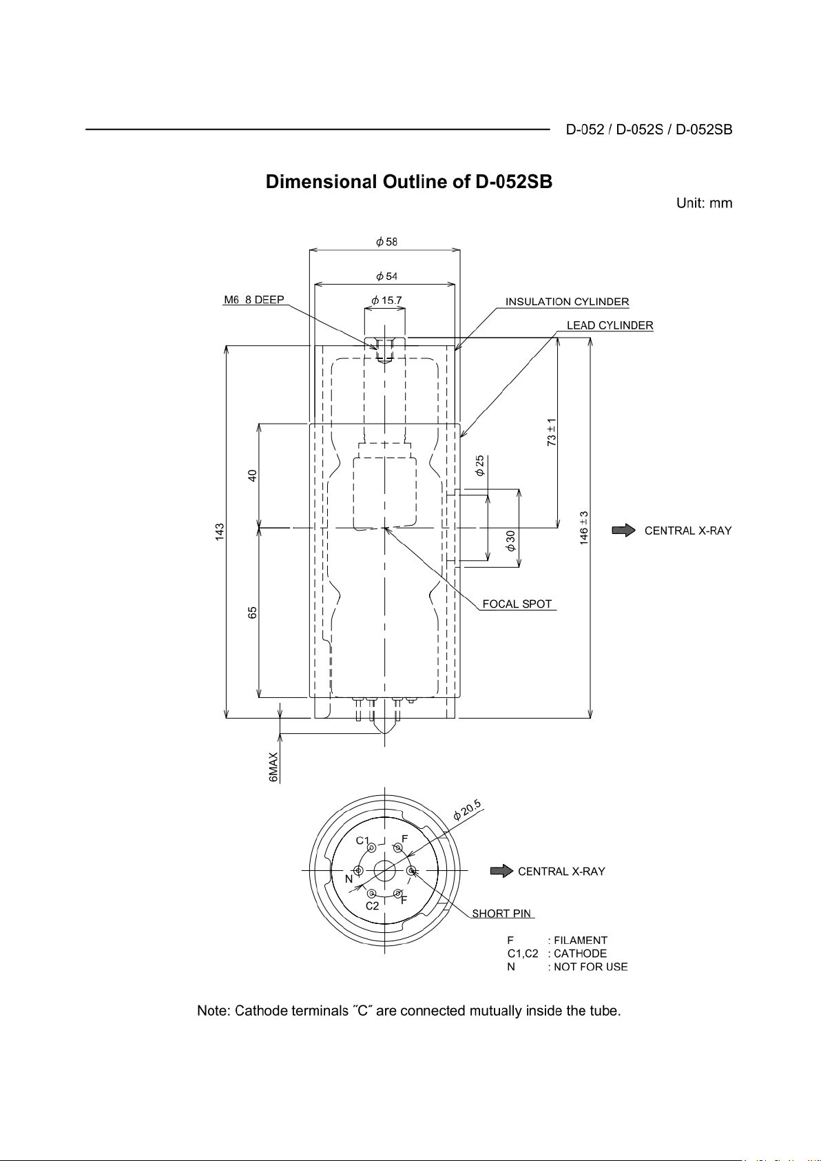
5°
9. Focal spot
0.5 (mm)
10. X-ray inherent filtration
Minimum 0.8 mm Al
11. Nominal X-ray tube voltage
50-100 kV
12. X-ray tube filament rating
3.5-4.9 V 3.5 A
13. Generator weight
Approx. 14.7 kg
14. Generator type
Class I
15. Standard assembling angle of X-ray generator
Horizontal/Perpendicular
16. Target angle of assembling X-ray generator
5°
17. Accuracy of X-ray tube (focal spot) assembled into X-ray generator
±0.5 mm
18. Focal spot when assembled into X-ray generator
0.5 mm
19. Duty cycle
Cooling time: 90 sec
20. Reproducibility of the radiation output
Coefficient of variation of the AIR KERMA is not greater than 0.05.
21. Accuracy of loading factors
The error of the value of the x-ray tube voltage is not greater than 10%.
The error of the value of the x-ray tube current is not greater than 20%.
The error of the value of the x-ray tube irradiation time is not greater than 5%+50ms.
The error of the value of x-ray tube current time product is not greater than±(10%+0.2mAs).
6. Aluminum (Filter material)
Part name: filter
Aluminum equivalent amount: 1.5 mm Al
7. Power supply impedance
0.3 W
8. Duty Cycle of Actuator for lifting equipment
10%, Max 2 Min ON / 18 Min OFF
21-2
Page 79
B02-T216E-A Bel-Cypher Pro
21-3
Page 80
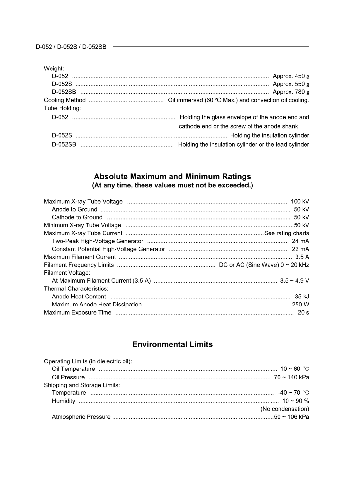
B02-T216E-A Bel-Cypher Pro
21-4
Page 81
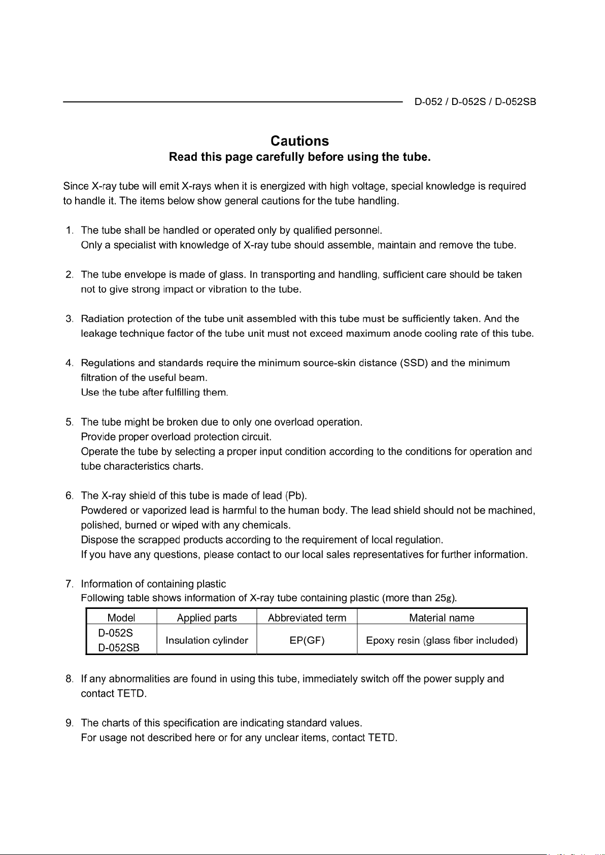
B02-T216E-A Bel-Cypher Pro
21-5
Page 82
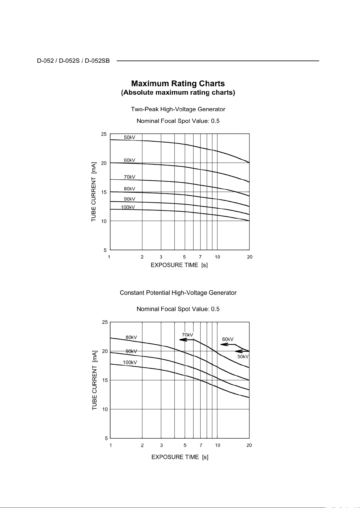
B02-T216E-A Bel-Cypher Pro
21-6
Page 83
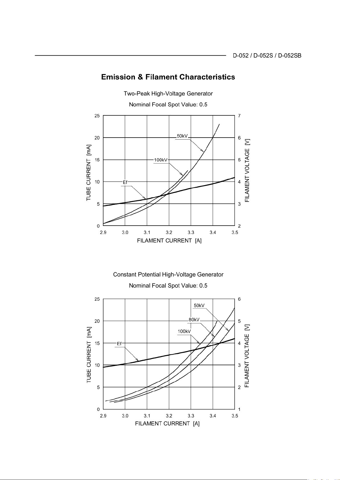
B02-T216E-A Bel-Cypher Pro
21-7
Page 84
B02-T216E-A Bel-Cypher Pro
21-8
Page 85
B02-T216E-A Bel-Cypher Pro
21-9
Page 86
B02-T216E-A Bel-Cypher Pro
WARNING
22
22.Maintenance
High voltage is applied to inside of the equipment. Do not open the cover by yourself.
Before requesting a repair, turn the power of the equipment OFF, and unplug from the power outlet.
After you unplug the equipment, wait for 10 minutes before starting any service work.
Special knowledge and special measuring tools are required to check this equipment.
To ensure that the X-ray unit functions within the manufacturer’s specifications and remains in compliance
with Standards, daily checking (by visual inspection) and periodic maintenance by the dealer service
personnel are recommended.
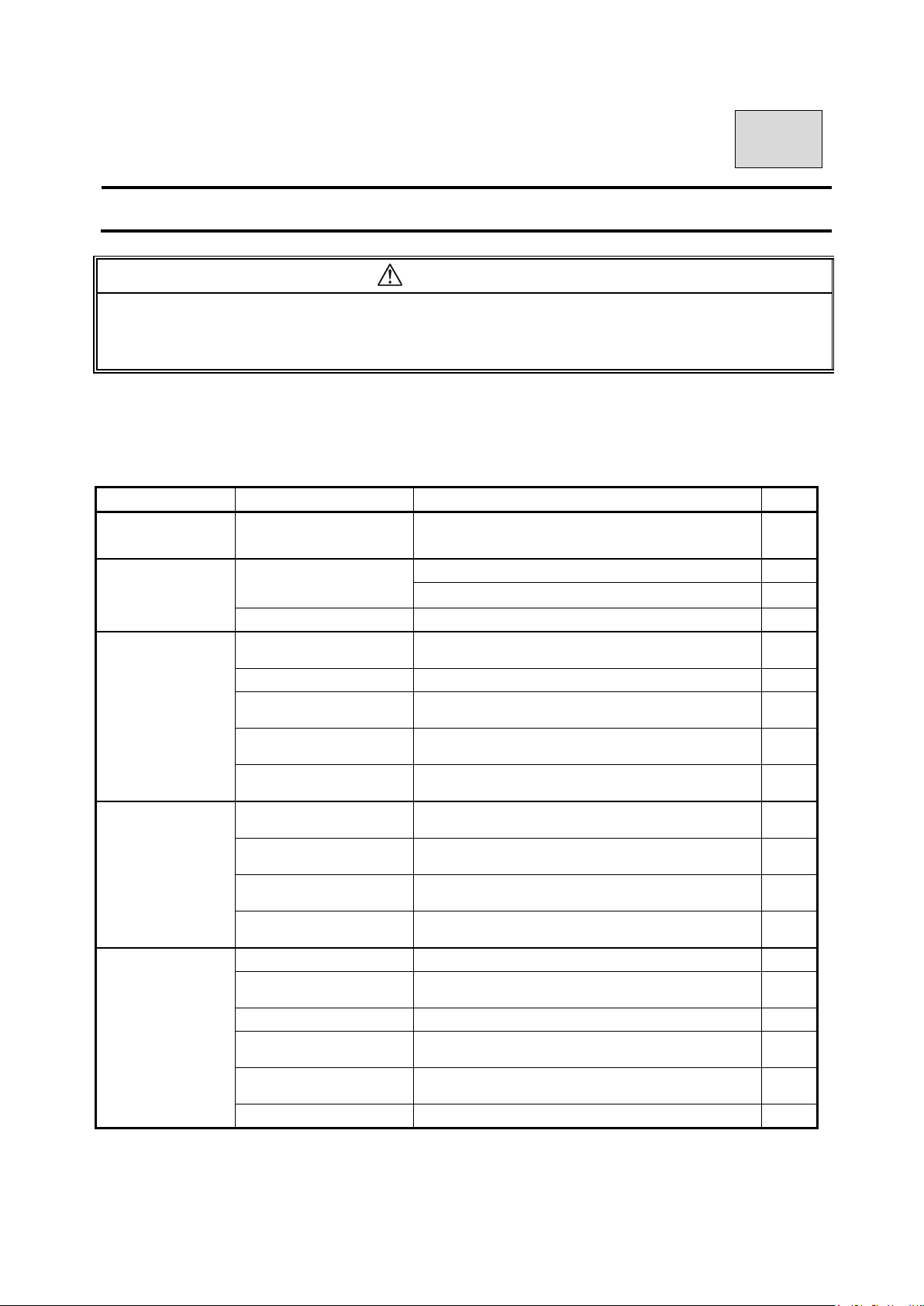
Maintenance by service personnel 1-2 times/year
Check Item Purpose Action
Method
Electricity
Condition
External
Appearance
Installation place
Safety Test for
Electric Shock
Movement
Accuracy
of the equipment
Check voltage range
External Appearance
Inside of the equipment Check for stains and dust
Temperature & Humidity
Level of floor Check the influence on the equipment
The Installation condition
of the equipment
Check obstacles
Rust
Insulation Resistance
Leakage current from the
outer cover
Earthing resistance
Resistance of the Earth
wire
Power Circuit voltage Check the voltage of the power circuit
Check Radiographic
Circuit
Check Control Circuit Check the movements of operating sequences
Accuracy of the
Positioning Mechanism
Check the Movement of
the Protection Circuit
Check display circuit Check the functions of display circuit ●
Check whether incoming voltage is within the
equipment’s requirement or not.
A) Deformation, scratches.
B) Warning Labels
Check compatibility of the environmental
conditions to operate the equipment
Check vibration and movement stability of the
equipment
Make sure that there are no obstacles within the
movement range of the equipment
Check the condition of rust. Evaluate the influence
on safety.
Check the resistance between a power line and
the earth
Check the current which is leaked from
the outer cover of the equipment to the earth
Check the resistance value between an exposed
metal and the earth
Resistance between the earth terminal and the
earthing point
Check the wave shape and the setting values of
the radiographic circuit
Check the deterioration of the positioning
mechanism
Check the setting values of the protection circuit.
Check the movement of the protection circuit.
●
◎
◎
●
●
●
●
◎
◎
●
●
●
●
●
●
●
●
●
22-1
Page 87
B02-T216E-A Bel-Cypher Pro
If oil adheres to the skin, please wash with plenty of water and soap.
Check Item Purpose Action
Method
Display during an
exposure
X-ray Generator
Radiographic
mechanism
Sliding mechanism
X-ray output
Checking Methods
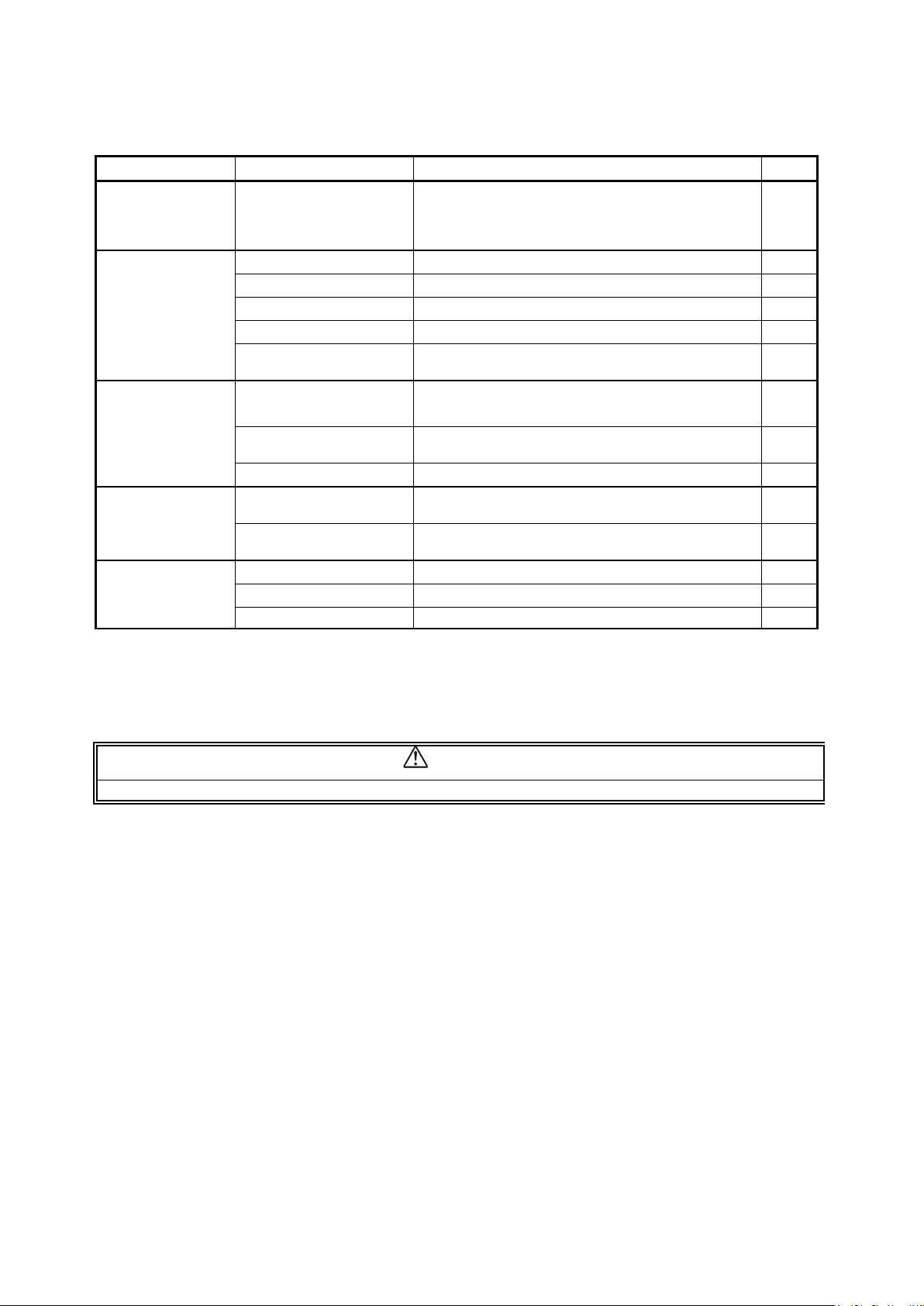
◎:Check by eyes during a daily operation
●:Check by a service personnel.
Check irradiation of
X-ray and “X-RAY ON”
display are in sync
X-ray tube Check the leakage of insulation oil ◎
Low voltage cables Check wear, damage, tension, and twist ◎
Cone Check looseness, transformation, and damage ◎
Filter Check transformation and damage ◎
Slit Plate (Collimator)
Movement of the
Arm Unit ASSY
Patient Positioning
Mechanism
Positioning beams Check the brightness and the positioning accuracy
Upward / downward
movements
Drop prevention
mechanism
X-ray Tube Voltage Check X-ray Tube voltage
X-ray Tube Current Check X-ray Tube current
Exposure Time Check exposure time
Check this while X-ray is irradiated. ◎
Check off-alignment of exposure field. Confirm the
exposure width
Check slip, abnormal sound, and stopping
accuracy
Play, looseness, operational performance, and
safeness
Check smoothness of movement
Check safety mechanism works properly ●
●
◎
◎
◎
◎
●
●
●
CAUTION
22-2
Page 88

B02-T216E-A Bel-Cypher Pro
23
23.Contact Information
Belmont Equipment
A Division of TAKARA BELMONT USA, Inc.
101 Belmont Drive
Somerset, NJ 08873
Toll Free (800) 223-1192
Toll Free Fax (800) 280-7504
www.belmontequip.com
TAKARA COMPANY, CANADA, LTD.
2706 South Sheridan Way
Mississauga, Ontario, Canada L5J 2M4
Toll Free (800) 268-5351
Fax (905) 822-6203
www.takarabelmont.ca
23-1
Page 89

B02-T216E-A Bel-Cypher Pro
24
24.Revision data of this manual
This manual was created in Sep 2016.
Revised in July 2017
Document number :B02-T216E Bel-Cypher Pro
24-1
 Loading...