

Page 1
VACUUM VALVE SERVICE & MAINTENANCE
PRIOR TO STERILIZATION
Minimize the potential accumulation of debris that could interfere with the operation of the instrument by flushing clean
water through it while working the valve lever open and
closed several times.
1. Using mild cleaner and water, wipe all surfaces of the
valve and dry with a clean, soft cloth.
OPERATOR’S GUIDE
BDS-2561 LEFT/RIGHT DUO DELIVERY SYSTEM
The Belmont BDS-2561 Left/Right cabinet mounted Duo Delivery System features an
automatic panel mount control for three handpieces, expandable to four with doctor ’s
3-way air/water syringe, master on/off with indicator, individual handpiece adjustment,
non-retraction water coolant with on/off, individual water coolant adjustment, 4-hole
Midwest oblate handpiece tubing, and a wet/dry type foot control.
2. Use a stiff HVE or SE cleaning brush of an appropriate
size to dislodge internal buildup.
NOTE
Do not ultrasonically clean, as instrument surface
finishes may be damaged.
PERIODIC MAINTENANCE
If the operation of the valve becomes sticky or stiff it may be
necessary to remove the valve spool for a thorough cleaning
and lubrication. Refer to the appropriate exploded view
shown in Figure 4.
1. Gently lift one end of the plastic on/off lever (V-1103/V-
1203) out from the indentation on the end of the spool.
2. Push the spool out of the valve toward that side and com pletely disengage the lever from the other end.
3. Clean the spool and inspect O-rings and replace those that
have nicks, cuts, flat spots or show signs of wear. Lubri cate O-rings with O-ring lube then reassemble the valve.
SURFACE DISINFECTION
Bleach or Sodium Hypochlorite solutions may permanently
damage the valve. Some surface disinfectants that will not
harm the valve are Birex SE, Sporicidin, Coldspor, Procide
Spray, Sterall Spray, Asepti-IDC, Biocide, Promedyne, IodoFive, Wescodyne, and Cavicide.
METHODS OF STERILIZATION
You may sterilize Belmont Autoclavable Valves by any of the
following methods: Chemical Vapor Method, Ethylene Oxide,
Steam Autoclave or Dry Heat.
OPERATING/CONTROL INSTRUCTIONS
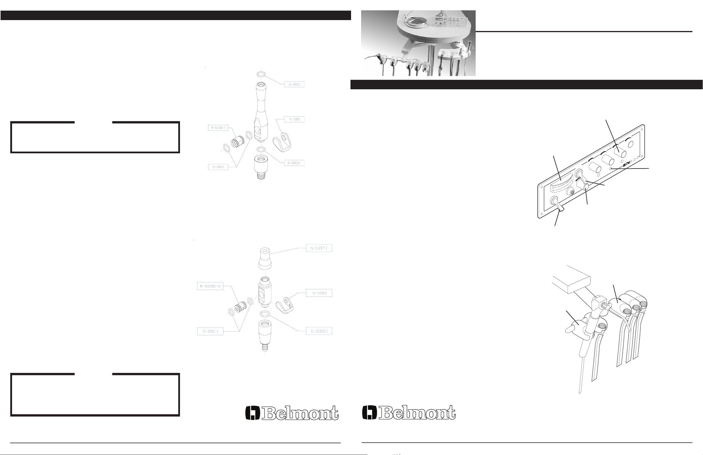
All controls are located on the front panel. Figure 1 shows
the location and identifies the function of these controls.
MASTER ON/OFF
Turns on air and water for the complete system. Flip toggle
forward to activate system. Always turn the toggle OFF
when not in use.
MASTER ON/OFF INDICATOR
Provides visual proof that the system is pressurized when
the MASTER ON/OFF is in the ON position.
DRIVE AIR PRESSURE CONTROL
Allows handpiece to be adjusted to its manufacturer’s
recommended operating pressure. Turn the adjusting screw
counter clockwise to increase the pressure, clockwise to
decrease the pressure.
DRIVE AIR PRESSURE GAUGE
Indicates drive air pressure to the handpiece.
HANDPIECE FLUSH CONTROL
Activates handpiece high volume water flow through handpiece water coolant lines. Flip the toggle up to activate the
system.
WATER COOLANT FLOW CONTROL
Allows adjustment to be made to the handpieces. Turn the
knob counter clockwise to increase the flow, clockwise to
decrease the flow.
Figure 2 shows automatic handpiece holder & syringe
holder assembly.
AUTOMATIC HANDPIECE HOLDER
Signals the automatic control system to supply drive air and
air/water coolants to handpiece as it is lifted from its holder.
When the handpiece is placed back into its holder, a signal
to the automatic control system stops the drive air and
air/water coolant supply.
WATER COOLANT FLOW
ADJUSTMENT (3 PLACES)
HANDPIECE DRIVE
AIR PRESSURE
GAUGE
FLUSH
HANDPIECE WATER LINE
FLUSH CONTROL
MASTER
AIR COOLANT FLOW
ADJUSTMENT
UNIT MASTER
ON/OFF
Figure 1. Handpiece control functions.
AUTOMATIC HANDPIECE
HOLDER (3 PLACES)
SYRINGE
HOLDER
HANDPIECE
DRIVE AIR
ADJUSTMENT
(3 PLACES)
NOTE
Temperature should never exceed 280 degrees Farenheit, or 138 degrees Celsius. Do not place the instrument in close proximity to the sterilizer heating element.
Avoid contact with the sterilizer walls.
Figure 4. Vacuum Valves.
A DIVISION OF TAKARA BELMONT USA, INC.
101 Belmont Drive Somerset, NJ 08873
Phone: (800) 223-1192 Fax: (732) 356-1035
FOOT CONTROL
Is used to regulate the drive air to the active handpiece. To
operate, apply pressure to the foot control cover.
A DIVISION OF TAKARA BELMONT USA, INC.
101 Belmont Drive Somerset, NJ 08873
Phone: (800) 223-1192 Fax: (732) 356-1035
Figure 2. Automatic handpiece holder assembly.
03-24-10 Rev. E 0097-225
Page 2
FINAL ADJUSTMENTS
SYRINGE SERVICE & MAINTENANCE
Adjust air and water regulated pressure.
Adjust handpiece pressure.
Check for any leaks.
CLEANING
BARRIER TECHNIQUE
The first choice in the protection of dental equipment should be the use of disposable barrier products. The repeated use of
disinfectants on equipment surfaces without the constant removal of the solution residue will eventually cause some damage
to equipment surfaces.
CHEMICAL DISINFECTION
The manufacturer of the disinfectant to be used should be contacted for them to state that the disinfectant will not damage
equipment surfaces including upholstery.
UNACCEPTABLE DISINFECTANTS
The following chemicals may damage equipment and upholstery:
* Alcohol based solutions
* Bleach
* Phenol/Alcohol combinations
* Foam spray products
USE WITH CAUTION
* Water based phenolic disinfectants following exactly the instructions for use.
BELMONT WARRANTY DOES NOT COVER DAMAGE TO EQUIPMENT AND UPOHOLSTERY CAUSED BY
DISINFECTANT SOLUTIONS.
WARRANTY
Belmont Equipment is warranted by the manufacturer to be free from defective material and workmanship under normal use and service, for a
period of two (2) years from date of shipment to the Buyer, except that any part or parts that are replaced under this Warranty within ninety (90)
days of the completion of the two year period shall be warranted to be free from defective material and workmanship for a period of ninety (90)
days from date of shipment of said parts to Buyer. Belmont will repair or replace any defective part under this Warranty, provided the part is
returned to our factory with prepaid postage, delivery or freight charges. In the event Warranty service must be performed to correct any defect,
only Belmont and/or one of its authorized dealers shall provide same upon mutually agreeable arrangements made in advance.
Except as otherwise provided herein, there is NO WARRANTY, representation or condition of ANY KIND, express or implied (including NO
WARRANTY OF MERCHANTABILITY OR FITNESS) and none shall be implied by law. THE EXPRESS WARRANTY AND THE REMEDIES
CONTAINED HEREIN (1) ARE MADE SOLELY TO THE FIRST PURCHASER FOR BENEFICIAL USE (THE BUYER), (2) ARE THE SOLE
WARRANTIES AND REMEDIES, (3) ARE IN LIEU OF ALL OTHER WARRANTIES, GUARANTEES, AGREEMENTS OR OTHER LIABILITIES,
WHETHER EXPRESS OR IMPLIED, AND ALL OTHER REMEDIES FOR BREACH OF WARRANTY OR ANY OTHER LIABILITY OF
BELMONT. IN NO EVENT SHALL BELMONT BE LIABLE FOR CONSEQUENTIAL OR INCIDENTAL DAMAGES.
No person, agent, distributor or dealer is authorized to change, modify or extend the terms of the Warranty in any manner, whatsoever.
*
TIP STERILIZATION
TROUBLE SHOOTING
1. To remove syringe tip, push in collar ring, then firmly grasp
tip and pull away from syringe head.
Solution: Replace the button assembly #3085. To
remove the button, hold buttons down,
2. After sterilization, replace the tip by pushing in collar ring
on syringe, then by inserting tip until it is firmly seated.
remove the retaining pin & gently lift under
the button. When re-installing the button, be
sure the spring is properly seated, with the
Release collar ring to lock tip securely to syringe.
smaller end facing upward. While holding
both buttons down, insert the retaining pin
through the syringe head.
NOTE
Be sure to rinse all cleaning agents from the tip prior to
sterilization. You may sterilize syringe tips by any of the
following methods; Chemical Vapor, Ethylene Oxide or
Steam Autoclave. Temperatures should never exceed
Alternatively, you may replace the O-rings on
the button assembly, using Syringe Repair Kit
#3066. After removing the button, slide the E ring from the stem, and pull the button from
the spool.
280 degrees Farenheit, (138 degrees Celsius).
Solution: Check first to ensure that the syringe tip is
undamaged and fully seated in the tip adapter
INSTALLATION
1. Turn off AIR and WATER supplies.
2. Unscrew syringe handle and determine which fitting leads
to the air button.
3. Slide syringe handle down over the syringe tubing. Select
the air side of the syringe tubing and connect to the air
fitting on the syringe.
4. Repeat with the water tubing to the water fitting. Ensure
that the unit end of the syringe tubing is properly connect ed to the air and water supply fittings on the dental unit.
Recommended operating pressures:
AIR 80 psi, WATER 40 psi.
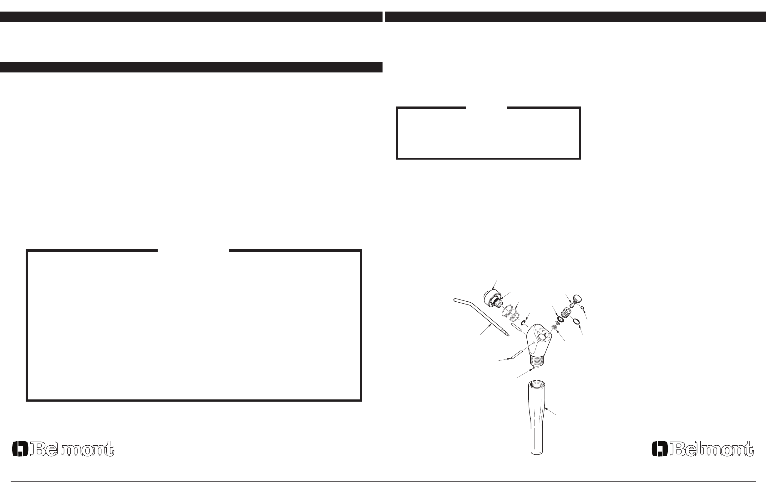
3065
2202
9677
2201
3085
Button Assembly
2203
assembly. If it is the O-ring (#2201) under the
tip adapter assembly it should be replaced.
Remove the tip, and use a 5/32 inch hex key
to unscrew the assembly from the syringe
head. Use a dental pick or a bent paper clip to
remove the small O-ring from the bottom of
the bore in the syringe body. Be careful not to
nick or scratch the sealing surfaces. The best
way to install the replacement O-ring is to slip
it onto the end of a syringe tip, apply silicone
lubricant, then insert it into the bore.
Before reinstalling the tip adapter assembly,
look down into the bore in the syringe body
and assure that the alignment pin is in place.
With the spring in place in the collar, align the
slot in the collar with the pin, then push the
collar into the syringe body. Tighten the
assembly firmly, holding the hex key by the
short end, with the long end inserted into the
tip adapter assembly. By holding the hex key
this way, you will have approximately the right
torque.
2211
3060
2212
9670
Problem: Water leakage aroung the buttons
Problem: Water spray when air button is pressed
This warranty is void when failure or defect is caused by conditons beyond the manufacturer’s control, such as damage resulting from mishandling, neglect, misuse, improper maintenance, accident or alteration or repair by anyone other than Belmont or an authorized Belmont
dealer.
Labor required to repair, replace or retrofit is not included during the warranty period by the manufacturer.
A DIVISION OF TAKARA BELMONT USA, INC.
101 Belmont Drive Somerset, NJ 08873
Phone: (800) 223-1192 Fax: (732) 356-1035
9648
0084
3491
Figure 3. Syringe.
A DIVISION OF TAKARA BELMONT USA, INC.
101 Belmont Drive Somerset, NJ 08873
Phone: (800) 223-1192 Fax: (732) 356-1035
 Loading...