

Page 1

R
Bel-Halo
IMPORTANT
LED DENTAL LIGHT
Model AL-920Q
INSTALLATION
and
OPERATION INSTRUCTIONS
After installation is completed, check all the bolts,
screws and fastners to conrm that they are
securely fastened.
Page 2

TABLE OF CONTENTS
Page
[1] MAJOR PARTS IDENTIFICATION
[2] SPECIFICATIONS
[3] CLASSIFICATION
[4] WIRING DIAGRAM
[5] DIMENSIONS
------------------------------------------------------
------------------------------------------------------
----------------------------------------------------
------------------------------------------------------------
[6] INSTALLATION
--------------------------------
6-1. Attach the light assembly to the light pole -----------------------
6-2.
Feed the light assembly wire harness through the swing arm
6-3. Attach the switch box -----------------------------------------------
1
1
1
2
3
3
-------- 3
4
6-4. Attaching wire harness from light assembly and power
supply box on the switch box ------------------------------------ 4
6-5. Attach the switch box cover ----------------------------------------
6-6. Wiring between Switch box and power supply box -------------
5
5
6-7. Wiring between LED light control PCB and
chair control PCB -------------------------------------------------- 7
7-1. Mode selection switch ----------------------------------------------
7-2. Operation of the touch-less switch --------------------------------
7-3. Selection of intensity for normal treatment mode --------------
8-1. Adjustment of the tension of the balance arm --------------------
8-2 Adjustment of the angle of the light head -------------------------
[7] OPERATION
[8] ADJUSTMENT OF THE BALANCE ARM
[9] CLEANING, MAINTENANCE PARTS & DISPOSAL
[10] MAINTENANCE AND INSPECTION
----------------------------11
8
8
8
9
9
---------10
Page 3
Intended Use of the Product
WARNING
Manufacturer
Caution
It means “caution,
warnings, or possibility to
danger”.
This product is intended for the exclusive use for diagnoses, treatments and relative pro-
cedures of dentistry, and must be operated or handled by the qualied dentists or by dental
staffs under the supervision of the dentist. Such dentists or dental staffs should instruct
and/or assist the patients to approach to and leave from the product. Patients should not be
allowed to operate or handle the product unless he/she is so instructed.
Operation of a dental light under Electro Magnetic Interferences.
This equipment may malfunction by electromagnetic interferences.
Do not install dental light close to the equipment that generates electromagnetic interference
(i.e. communication equipment, elevator)
Do not use the device that creates interference (i.e. cellular phone) near this equipment.
Do not use electric surgical knife or laser knife with dental light.
Light may turns on/off by itself due to malfunction of a sensor caused by electromagnetic interferences.
Symbols
Environmental condition for Operation
Temperature : 41~104F (5 ~ 40℃)
Humidity : 10 ~ 80%
Pressure : 8.7~15.4 psi (600 ~ 1060 hpa)
Environmental condition for Storage
Temperature : -4~158F ( -20 ~ 70℃)
Humidity : 10 ~ 80%
Pressure : 8.7~15.4 psi (600 ~ 1060 hpa)
Environmental condition for Transportation
Temperature : -4~158F (-20 ~ 70℃)
Humidity : 10 ~ 80%
Pressure : 8.7~15.4 psi (600 ~ 1060 hpa)
Page 4

WARNING
WARNING
CAUTION
CAUTION
•
To avoid the risk of electric shock, this equipment must only be connected to supply mains with protective earth.
• Position a light head by holding light handle(s).
• Installation and service work should be conducted by an authorized installation/service personnel only.
The followings are prohibited
• To modify this equipment.
• To use the equipment under any failure condition.
• To use the equipment without doing the daily and periodical check-up.
• To wipe the plastic covers with any disinfectant or detergent that contains organic solvent.
Precautions for Installation
• Keep the equipment away from water.
•
Keep in circumstances safe from inuence by temperature, humidity, wind, sun light, air containing salts and minerals.
• Care about stability such as inclination, vibration and impact, including handling and transportation.
• Do not keep the equipment in a place where chemicals are or where gas is emitted.
• During lifting and unpacking of the light, make sure to hold only the designated parts.
• Do not drop or hit the light.
• Do not connect to power supply other than AC120V 60HZ.
• Ground light properly prior to turning power on.
•
When the installation process has been completed, verify that all the mechanical and electrical functions are working properly.
• Thick gloves are highly recommended at unpacking.
• Do not modify this equipment.
Before use
• Check connection of switches and make sure that the device functions properly.
• Make sure that grounding wire is connected.
• Make sure that cables are properly and perfectly connected.
During use
• Do not use the light longer than required for examination or treatment.
• Always watch the patient and the equipment to make sure nothing is wrong.
• If anything wrong is observed with the equipment or the patient, take a proper action, such as stopping
the use of equipment as well as keeping the patient in safe.
• Keep an eye on the patient not to touch the equipment.
After use
• Turn off the light.
• Clean the equipment and get it ready for use.
Do not spray liquids directly onto light surfaces.
systems, do not apply excess cleaning solution onto
In order to prevent damage to electrical components and
light surfaces.
NOTE
Warranty does not cover damage to equipment caused by disinfectant solutions
Page 5
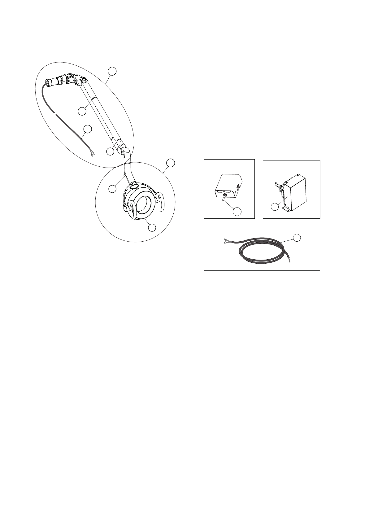
[1] MAJOR PARTS IDENTIFICATION
A
3
2
B
4
5
7
Switch Box
Power Supply Box
Power supply box wire harness
1
6
8
(A) LED light head assembly
(B) Balance arm assembly
1. Mode selection switch
2. Touchless sensor switch
3. Intensity control volume
4. Slot A for Adjusting Tension of Balance Arm
5. Slot B for Adjusting Angle of Head
6. Power supply box assembly
7. Light assembly wire harness
8. Power supply box wire harness
[2] SPECIFICATIONS
1. Focal Distance ......................................................... 25.6" (650 mm)
2. Color Temperature .................................................. 5000° Kelvin
3. Light Intensity
Regular Operation Mode ........................................ 4000 Lux / 370 FTC ~ 32000 Lux / 2970 FTC
Composite Mode .................................................... 5500 Lux / 510FTC
4. Light Pattern ............................................................ 3.2" x 5.5" at 25.6"
5. Power Requirement ................................................. AC. 120V / 60 Hz / 0.43A
[3] CLASSIFICATION
a. Protection against electric shock : Class I Equipment.
b. Equipment not suitable for use in the presence of a ammable anesthetic mixture with air or with
oxygen or nitrous oxide.
-1-
Page 6
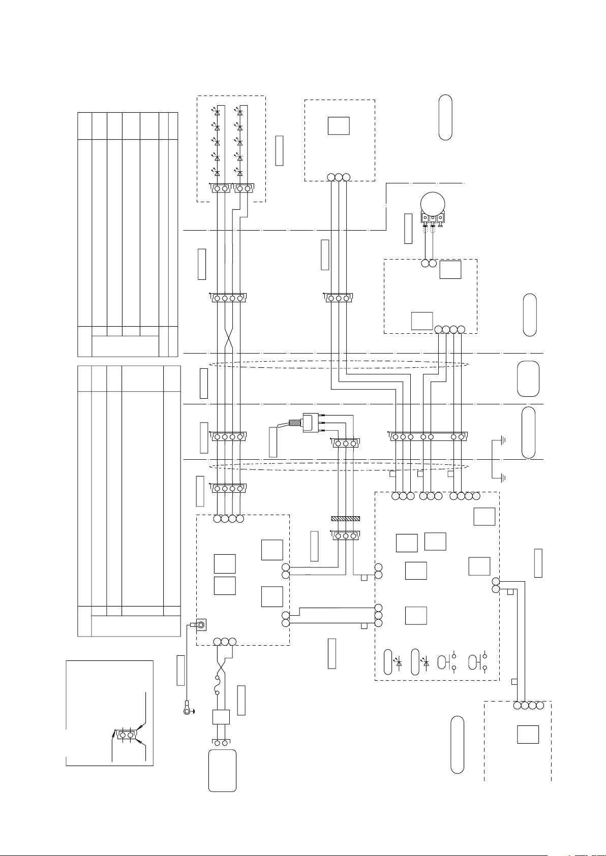
1A07X8**
5
9
CN9
JST
NH3P
4
10KB
3
1
312
SW2
1
S
M
6
L
N
SW1
JP3
SW4
2
1
SW3
1
2
3
4
OFF
ON
ON
OFF
OFF
OFF
OFF
8
7
6
5
SW3
XA3P
XA4P
122
1
CN1
JST
EH3P
312
432
1
321
CN2
JST
XA2P
CN1
JST
PH4P
1
2
CN5
JST
XH4P
CN4
JST
XA3P
213
4
213
312
4
CN1
JST
XH3P
CN6
JST
NH2P
CN201
JST
XH4P
CN202
JST
XH2P
CN204
JST
NH2P
CN101
JST
VH3P
4
213
312
21
1 2 3
1 2
21
OFF
OFF
123
4
XM4P
321
XA3P
1 2
4
213
CN8
JST
XA4P
CN11
JST
XA2P
8
11
1A07MR**
1A086X**
1A086Z**
1A0871**
1A086V**
1A07M9**
1A07MB**
1A07MA**
1G027U**
XA7P
321
4
5
6
7
XM4P
432
1
1A086W**
VL2P
2
1
XM3P
123
1A086Y**
AD10003M
20110429
AL-920Q
LED Module Assy.
SM2P(Black)
SM2P(Black)
LED module 1
LED module 2
Black
Black/White
Brown
Brown/White
Sensor power input
Sensor output
GND
Yellow
Green
Blue
LED Sensor PCB.
(1G0280**)
Head Section
Red
Orange
(VR) Intensity
adjustment
Intensity adjustment
Volume Section
Display LED PCB.(DL-900)
DC5V output
VR input
(1G027Z**)
DC5V power input 1
Display LED input
Red
Orange
Gray
Purple
VR output
DC5V power input 2
York Section
Trunk line for LED sensor PCB
Yellow
Green
Blue
Yellow
Green
Blue
Black
Black/White
Brown
Brown/White
Black
Black/White
Brown
Brown/White
Trunk line for LED module(Head)
Yellow
Green
Blue
Gray
Purple
Red
Orange
Yellow
Green
Blue
Gray
Purple
Red
Orange
Sensor power
output
Sensor input
DC5V power output 2
Display LED output
DC5V power
output 1
VR input
Arm ~ Pole
Green/Yellow
Power LED
Sensor Signal LED
LED2:Yellow
LED1:Green
Manual SW for
operation test
VR lower limit
setting
LED Light Control PCB.
(1G02A0**)
PWM output
DC5V
Power input
White
Black
+
-
Light Blue
Remarks
Connector Sym bol
SM ... SM Connecto r
XA .. . XA Connector
XM ... XM Connector
VL . .. VL Con nector
Plug
The side with black dot
has male pins
Receptacle
Black dot
Earth line for power PCB.
Green
Fuse
250V/0.8A(T)
Blue
Brown
AC120V
Power Input
Blue
Brown
To J-Box Section
connect to trunk line
for D light power.
(ANFT81**)
LED Light Power PCB.(DL-900)
(1G028U**)
LED output A1
LED output A2
LED output K1
LED output K2
GND
DC5V
Power input
PWM input
+
Black
White
Pink
Bright Green
Trunk line for S/M mode
selection sw.(AL-920Q)
Pink
Bright Green
Ferrite
Four turns
Light Blue
Pink
Bright Green
Black
Black/White
Brown
Brown/White
Black
Black/White
Brown
Brown/White
Black
Black/White
Brown
Brown/White
Sensor/Manual
Mode Selection Switch
Lead wire for inside arm
(AL-920Q)
Trunk line for chair inside
(AL-920Q)
Trunk line for LED module(power)
Trunk line for Control PCB.power
Chair Base Section
Chair Control PCB.
(AGFS13**)
SW Box Section
Brown
Red
Red
Brown
TXD
RXD
Serial reception
Serial communication line
(AL-920Q)
PC
PC
Setting condition
Transition time to Composite mode (by a sensor)
O: 1 second, On: 2 seconds
Combining dental unit
O: Clair unit, On: CP-One plus
Settings of PCB dip switches ( SW3,4) and jumper pin (JP3).
Default
setting
Setting condition
Sensor activation setting
O: Activate when a hand goes away, On: Activate when a hand comes in.
6 Includes Composite Mode
O:Yes, On: No
Speed setting of communication line
O: 4800bps, On: 2400bps
LED blink setting of Composite Mode
O: Slow blinking, On: Rapid blinking
PC side: Clair Unit, 232 side: CP-One plus
PC side: Clair Unit, 232 side: CP-One plus
Default
setting
Test mode ( Always OFF)
O: Normal operation, On: Test operation
2
1
3
4
Blue
Brown
Noise filter section(AL-920Q)
1A08AG**
GND
Wake-up brightness setting from light o condition.
O : 1. Composite Mode when a light is turned on by using a sensor.
: 2. Keeps on getting on/o signal from dr table, light stays in composite mode.
On : 1. Regular Mode when a light is turned on by using a sensor.
: 2. Keeps on getting on/o signal from dr table, light goes into regular mode.
[4] WIRING DIAGRAM
-2-
Page 7
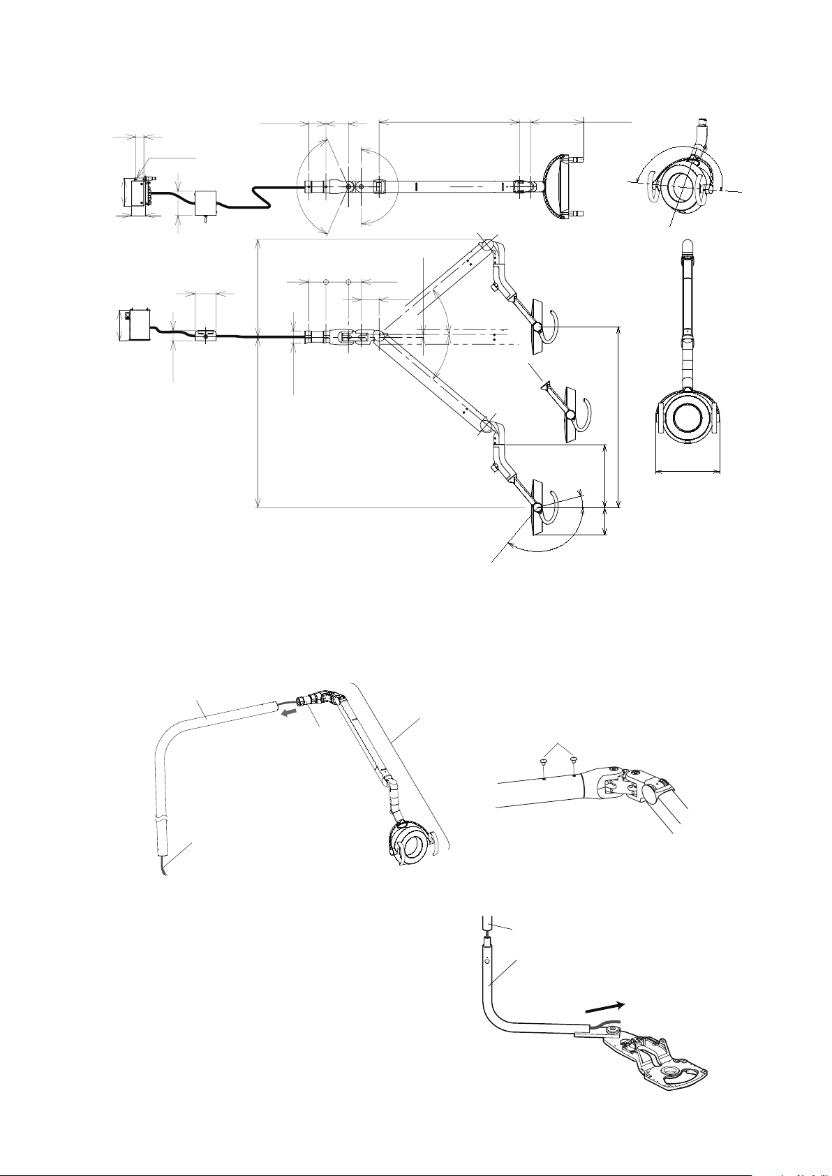
[5] DIMENSIONS
Light Arm
Swing Arm
Pull light assembly wire harness
from the light through swing arm
2-11/16”(67.5)
1-7/8”(48)
1-1/4”(30)
14-1/2”(369)
3-5/8”(91)
1-9/16”(39)
3-1/8”(80)
8-3/4”(223.5)
1-13/16”(46.5)
3/8”(10.3)
φ1-13/16”(46.8)
25-3/4”(657)
26-13/16”(681)
2-9/16”(65)
3-3/8”(85)
20-7/8”(530)
1/4”(6)
2-φ
2-9/16”(65)
3-3/8”(85)
9-3/8”(238.5)
4-3/16”(106)
10-7/16”(265)
5-5/8”(142.7)
4-1/8”(104.3)
2”(52)
130
º
15º
40
º
40
º
180
º
132
º
90º
90
º
Light Assembly
Light assembly
wire harness
Light Pole
Balance Arm
Joint
M6 x 12 mm
[6] INSTALLATION
6-1. Attach the light assembly to the light pole
of the light into the light pole. Fasten with two M6 x 12mm screws.
6-2. Feed the light assembly wire harness through the swing arm
Feed the light assembly wire harness through the
swing arm and pull the end of the harness from the
lower end of the swing arm.
Mount the light assembly onto swing arm.
Feed the wire harness coming from the balance arm joint through the light pole. Insert the balance arm joint
-3-
Page 8
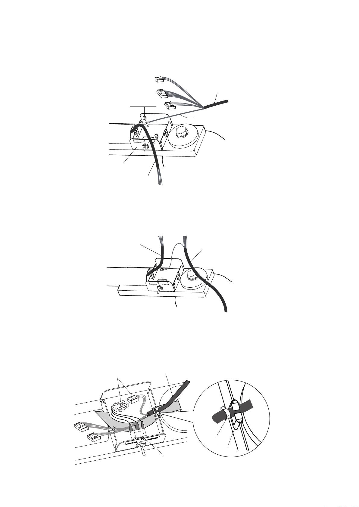
6-3. Attach the switch box
Green/Yellow
Power supply box wire harness
Light assembly wire harness
Switch Box
M4 x 8 mm
Light assembly wire harness
Power supply box wire harness
Connector(3 Pins)
Guide
Cable tie
Mode selection switch
Power supply box wire harness
Attach the switch box onto the swing arm with two screws M4 x 8mm.
Fix the Green/Yellow line from power supply box wire harness together with same screw as shown
in gure.
6-4. Attaching wire harness from light assembly and power supply box on the switch box.
(1) Attach the connectors of the light assembly wire harness and power supply box wire harness.
(2) As illustrated below, place the wire harness inside the guide. The part with the cable tie should be
inside the box. Lead all the wires underneath the switch, and connect the connectors (3 pins) from the
power supply box wire harness and the mode selection switch. See [4] Wiring diagrams.
-4-
Page 9
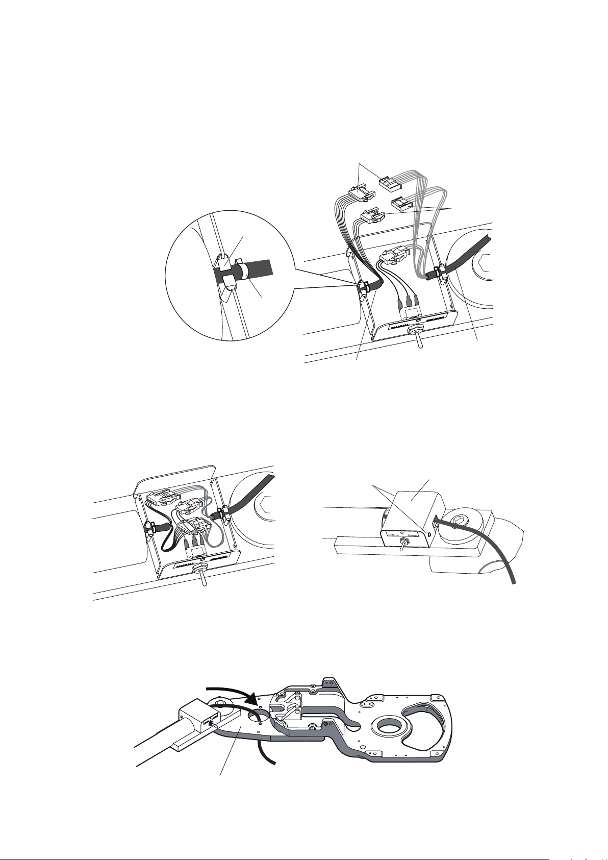
(3) As illustrated below, place the Light Assembly Wire Harness inside the cable guide. The part with the
Swing Arm Bracket
Power supply box
wire harness
Connector(4 Pins)
Connector(7 Pins)
Guide
Cable tie
Light assembly wire harness
M4 x 6 mm
Switch box cover
cable tie should be inside the box. Make sure that the Light Assembly Wire Harness should be above that
from the power supply box.
Connect the connectors (7 pins) of the wire harnesses.
Also connect connectors (4 pins) of the wire harnesses.
See [4] Wiring diagrams.
6-5. Attach the switch box cover
Put all the wires inside the box. Place the switch box cover on the switch box and x it with two M4 x 6mm
screws.
6-6. Wiring between switch box and power supply box assembly.
(1) Insert the wire harness down through the hole of the swing arm bracket.
-5-
Page 10
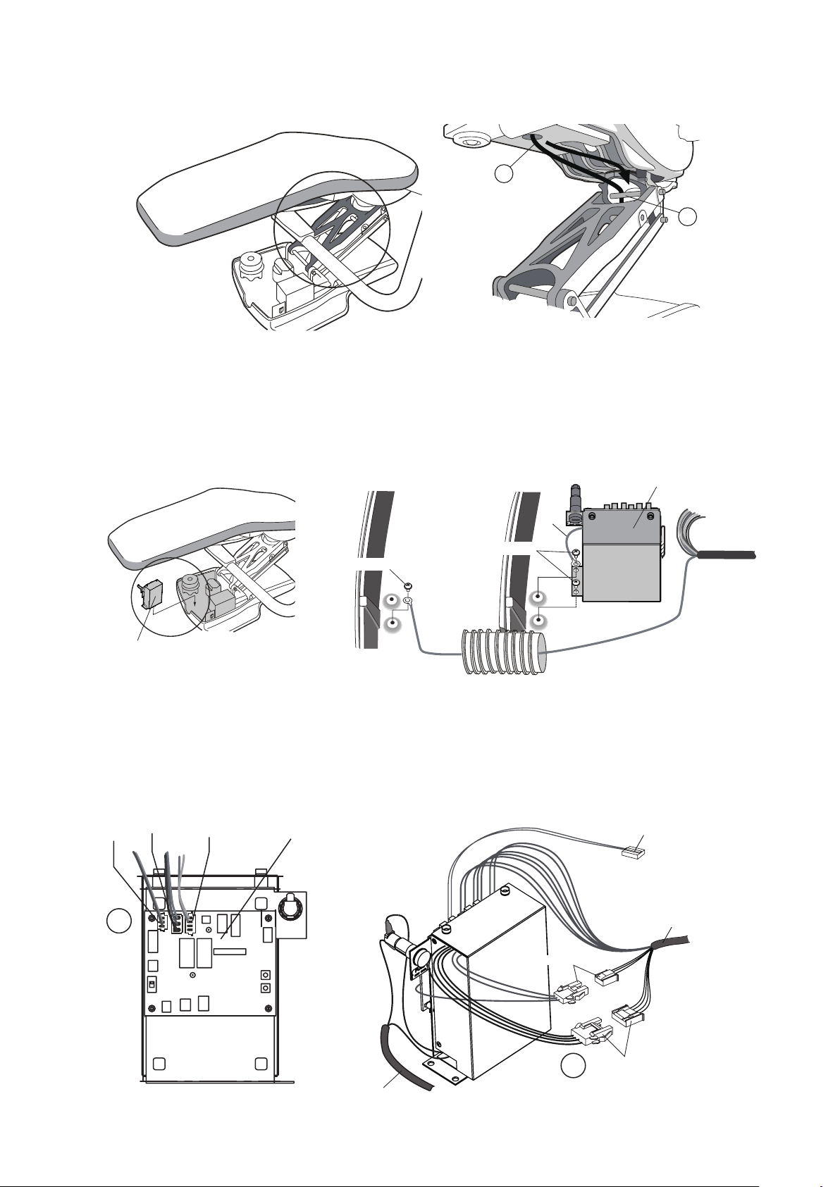
1
2
(2) Feed the wire harness through the ange parts as described below.
Green/Yellow
Power supply box
wire harness
M5 x 12mm
Junction Box
M5 x 12mm
Base
Green
Duct hose
Power Supply Box
Power Supply Box
3P
3P
4P
LED light control PCB
Power supply box
wire harness from switch box
Connector(4 pins)
Connector(3 pins)
Power supply wire
To chair control PCB.
(Serial communication line)
A
B
(3) Attach the power supply box by the motor pump of the chair with two M5 x 12mm screws.
Also x the Green line from power supply box together with same screw.
Fix the Green/Yellow line from power supply box wire harness to junction box with M5 x 12mm screw.
(4) Attach the connectors onto the LED light control PCB of the power supply box.
A :
Connect the connectors (3 pins, 3pins and 4 pins) from power supply box wire harness to LED light control PCB.
B : Connect the connectors (3pins and 4pins)
-6-
Page 11
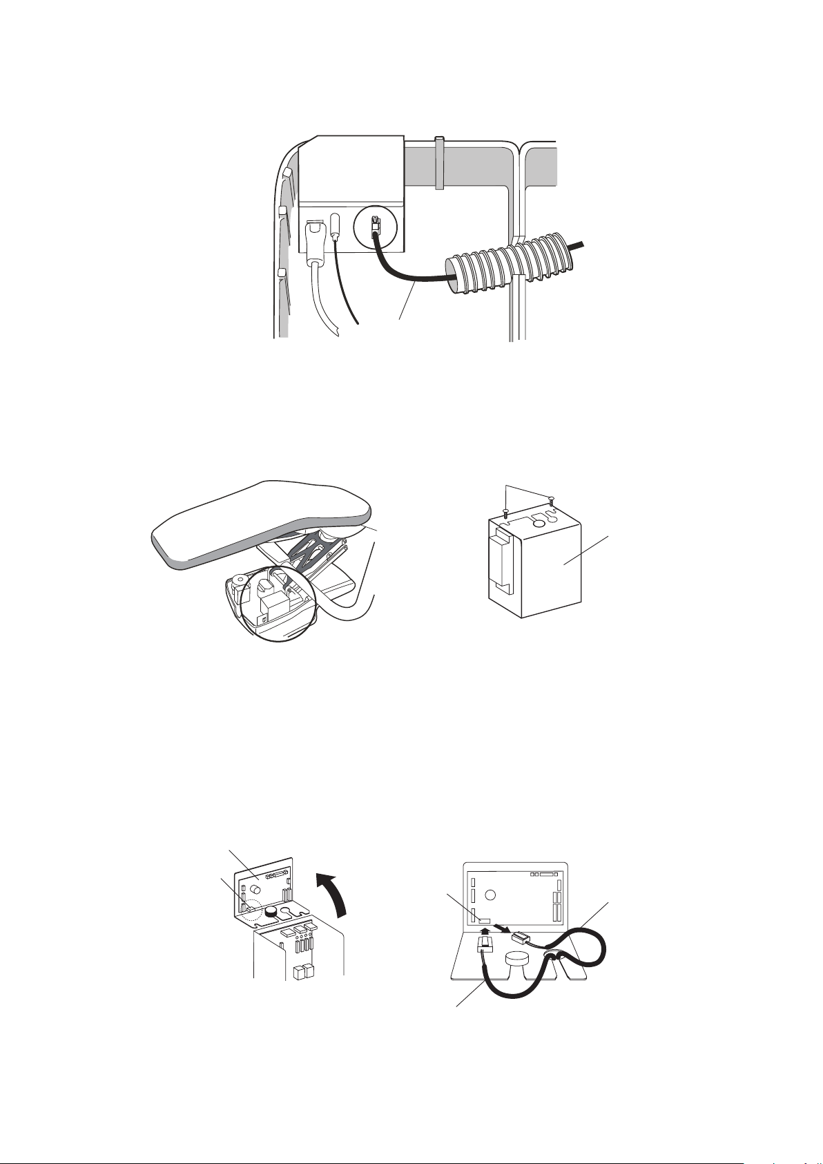
(5) Connect the power supply wire from power supply box to the connector on the metallic box inside
Power supply wire
Metallic box
Chair control PCB
CN8
Wire harness for AL-820
Wire harness for AL-920Q
from LED light power supply box
(Serial communication line)
CN8
Screws
Chair control PCB box
the junction box.
6-7. Wiring between LED light control PCB and chair control PCB.
(1) Remove 2 screws for chair control pcb box.
(2) Open the lid to access to the chair control PC board.
Remove the connected wire harness for AL-820 from CN8.
Replace with the wire harness for AL-920Q that comes out from LED light power supply box.
Close the lid and x with 2 screws.
-7-
Page 12
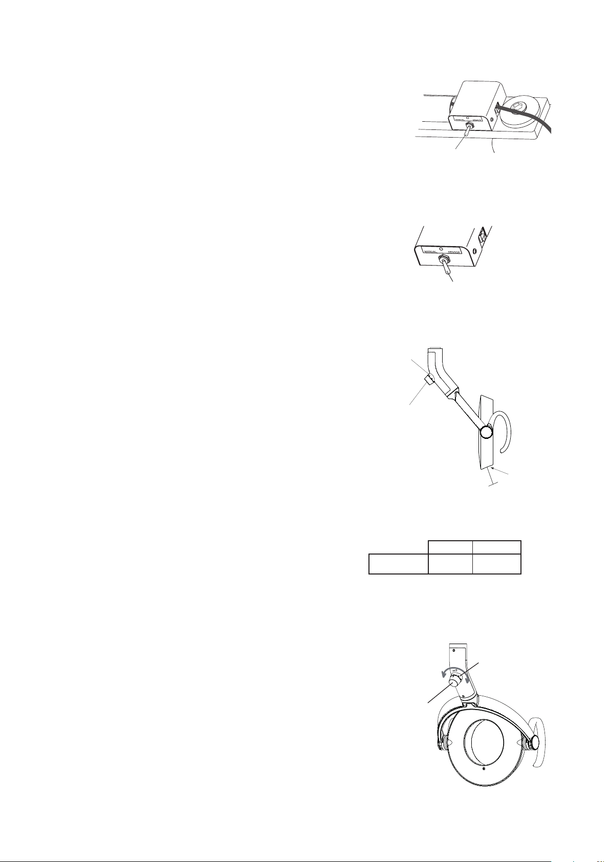
[7] OPERATION
Mode Selection switch
Mode Selection Switch
LED Display
Intensity Volume Control
Touch-less
Sensor Switch
Active distance
within 2-1/2”
Low
High
LED Display
Intensity Control
Volume
7-1. Mode Selection switch
Select the desired - sensor or manual mode with the
switch on the box.
Sensor : Touch-less ON/OFF and composite mode.
Manual :
Manual mode (ON only).
○ : OFF
7-2. Operation of the touch-less switch
The light can be turned on/off with a touch-less
sensor switch. The intensities are regular operation
mode and composite mode.
7-2-1. Conrmation of mode selection switch
Make sure that the mode selection switch is at Sensor mode.
7-2-2. Turning on/off
The touch-less switch has a sensor. The sensor
activates within the distance of 2-1/2" from the
surface. Let your hand pass by within 2-1/2" from the
touch-less sensor to turn on the light.
Let your hand pass by again to turn off.
7-2-3. Switching to the composite mode
During normal treatment mode, while the light is on,
place and hold your hand within 2-1/2" from the touch-less
sensor for 2 seconds. The light intensity will be automatically
reduced to the composite mode which has intensity of 5500 lux.
LED display under yoke blinks green on at composite mode.
To switch back to the normal treatment mode, place
your hand by the touch-less sensor 2 seconds again.
Note: by placing your hand for 2 seconds when the light is
off. The light does not lit in the composite mode,
but lit in normal treatment mode. Please make sure
that the light is on before lighting in composite mode.
7-3. Selection of intensity for normal treatment mode
LED display under yoke turns green on at regular
operation mode.
By turning intensity control volume, you can adjust
intensity steplessly between 4000 - 32000 Lux.
COMPOSITE
Mode
INTENSITY
5500 Lux Blink
LED Display
Note: If light intensity is set below 510 FTC and in composite mode,
light will Flash briey when exiting composite mode.
This is a normal condition indicating return to standard mode.
-8-
Page 13

[8] ADJUSTING TENSION of BALANCE ARM
Adjustment Bar
Slot A
(for tension)
Slot B
(for angle)
Hole C
(
Socket Screw
)
Hole C
When the light head tilts downward,
turn the nut to - direction.
When the light head tilts upward,
turn the nut to + direction.
8-1. Adjustment of the tension of the balance arm
Position the angle of the balance arm so the tension adjustment nut becomes visible
just under slot A.
Turn the nut and adjust the tension with the adjustment bar supplied with the light.
Direction of rotation of the nut
When the light head tends to go up, turn the nut to + direction.
When the light head tends to go down, turn the nut to – direction.
8-2 Adjustment of the angle of the light head
1) Use a 2mm hex key wrench to loosen socket screw in front of Hole C.
2) Position the angle of the balance arm so the head angle adjustment nut becomes visible just under
the slot B. Turn the nut and adjust the tension with the adjustment bar supplied with the light.
3) After adjustment is done, re-tighten the socket screw.
Note : Unless this socket screw is re-tightened, the angle of the head will be changed during use.
-9-
Page 14

CAUTION
[9] CLEANING,MAINTENANCE PARTS & DISPOSAL
9-1. Cleaning
Allow light to cool prior to cleaning.
Use a soft cloth or cotton only to gently clean surfaces. Use of other materials can scratch and
damage surfaces. Covers can be cleaned with a soft cloth or cotton moistened with alcohol.
The reector can be cleaned with a soft and dry cloth or cotton with extreme care.
9-2. Maintenance Parts
Fuse are maintenance parts.
Period for repair and supplying parts
We will supply parts of the equipment for 10 years, after the manufacturing of this equipment
is discontinued.
9-3. Lifetime
Provided that the recommended and authorized care and maintenance are correctly performed,
the working
lifetime of this equipment is 10 years from the date of initial shipment from the manufacturer.
9-4. Disposal
This is not an infectious device, but prior to disposal make sure that no parts of the device is
infected. Follow the federal, state and local regulations for disposal.
-10-
Page 15

< Fig.8 > < Fig.9 > <
Fig.10 >
Light bulb cover fixing screw
Cut out
Reflector cover
fixing gap
Light bulb cover fixing screw
Thread hole
Push and tighten until it clicks
Be careful not to pinch the wires
[10] MAINTENANCE AND INSPECTION
㻱㼒㻑 㻬㼗㼈㼐 㻩㼕㼈㼔㼘㼈㼑㼆㼜 㻬㼑㼖㼓㼈㼆㼗㼌㼒㼑㻃㻰㼈㼗㼋㼒㼇㻃㼄㼑㼇㻃㼇㼌㼄㼊㼑㼒㼖㼌㼖
㻬㼑㼉㼏㼘㼈㼑㼆㼈㻃㼌㼉㻃㼌㼑㼖㼓㼈㼆㼗㼌㼒㼑㻃㼌㼖
㼑㼒㼗㻃㼆㼒㼑㼇㼘㼆㼗㼈㼇
㻰㼄㼌㼑㼗㼈㼑㼄㼑㼆㼈㻃㼕㼈㼔㼘㼌㼕㼈㼇
㼌㼑㻃㼆㼄㼖㼈㻃㼒㼉
㼑㼒㼑㼆㼒㼑㼉㼒㼕㼐㼌㼗㼜
㻔
㻤㼓㼓㼈㼄㼕㼄㼑㼆㼈㻃㼒㼉㻃㻯㼈㼑㼖
㻦㼒㼙㼈㼕
㻥㼈㼉㼒㼕㼈㻃㼖㼗㼄㼕㼗
㻦㼋㼈㼆㼎㻃㼇㼈㼉㼒㼕㼐㼄㼗㼌㼒㼑㻏㻃㼖㼆㼕㼄㼗㼆㼋㼈㼖㻃㼅㼜
㼈㼜㼈㼖
㻧㼈㼗㼈㼕㼌㼒㼕㼄㼗㼌㼒㼑㻃㼒㼉㻃㼒㼓㼗㼌㼆㼄㼏
㼓㼈㼕㼉㼒㼕㼐㼄㼑㼆㼈
㻦㼋㼄㼑㼊㼈㻃㼄㻃㼏㼈㼑㼖㻃㼆㼒㼙㼈㼕㻑
㻯㼌㼊㼋㼗㻃㼖㼚㼌㼗㼆㼋 㻥㼈㼉㼒㼕㼈㻃㼖㼗㼄㼕㼗
㻶㼈㼗㻃㻶㼈㼑㼖㼒㼕㻒㻰㼄㼑㼘㼄㼏㻃㼖㼚㼌㼗㼆㼋㻃㼗㼒㻃㻰㼄㼑㼘㼄㼏㻑
㻦㼒㼑㼉㼌㼕㼐㼖㻃㼗㼋㼈㻃㼏㼌㼊㼋㼗㻃㼗㼘㼕㼑㼖㻃㼒㼑㻑
㻯㼌㼊㼋㼗㻃㼇㼒㼈㼖㼑㻊㼗㻃㼉㼘㼑㼆㼗㼌㼒㼑㻑 㻵㼈㼓㼏㼄㼆㼈㻃㼄㻃㼏㼌㼊㼋㼗㻃㼅㼘㼏㼅㻑
㻷㼒㼘㼆㼋㼏㼈㼖㼖㻃㼖㼈㼑㼖㼒㼕 㻥㼈㼉㼒㼕㼈㻃㼖㼗㼄㼕㼗
㻶㼈㼗㻃㻶㼈㼑㼖㼒㼕㻒㻰㼄㼑㼘㼄㼏㻃㼖㼚㼌㼗㼆㼋㻃㼗㼒㻃㻶㼈㼑㼖㼒㼕㻑
㻦㼒㼑㼉㼌㼕㼐㼖㻃㼗㼋㼈㻃㼏㼌㼊㼋㼗㻃㼗㼘㼕㼑㼖㻃㼒㼑㻑
㻯㼌㼊㼋㼗㻃㼇㼒㼈㼖㼑㻊㼗㻃㼉㼘㼑㼆㼗㼌㼒㼑㻑
㻦㼏㼈㼄㼑㻃㼗㼋㼈㻃㼖㼈㼑㼖㼒㼕
㼖㼘㼕㼉㼄㼆㼈㻑
㻬㼑㼗㼈㼑㼖㼌㼗㼜㻃㼖㼚㼌㼗㼆㼋 㻥㼈㼉㼒㼕㼈㻃㼖㼗㼄㼕㼗 㻦㼋㼄㼑㼊㼈㻃㼌㼑㼗㼈㼑㼖㼌㼗㼜㻑
㻬㼗㻃㼐㼄㼜㻃㼆㼄㼘㼖㼈㻃㼗㼋㼈㻃㼇㼌㼉㼉㼌㼆㼘㼏㼗㼜
㼄㼗㻃㼇㼈㼑㼗㼄㼏㻃㼓㼕㼄㼆㼗㼌㼆㼈㻑
㻷㼘㼕㼑㻃㼒㼉㼉㻃㼗㼋㼈㻃㼏㼌㼊㼋㼗㻑㻃㻦㼄㼏㼏
㼆㼘㼖㼗㼒㼐㼈㼕㻃㼖㼈㼕㼙㼌㼆㼈㻑
㻩㼘㼑㼆㼗㼌㼒㼑㼄㼏㼌㼗㼜㻃㼒㼉
㻥㼄㼏㼄㼑㼆㼈㻃㻤㼕㼐
㻥㼈㼉㼒㼕㼈㻃㼖㼗㼄㼕㼗
㻶㼚㼌㼑㼊㻃㼗㼋㼈㻃㼅㼄㼏㼄㼑㼆㼈㻃㼄㼕㼐㻃㼘㼓㻒㼇㼒㼚㼑㻑
㻶㼚㼌㼑㼊㻃㼗㼋㼈㻃㼅㼄㼏㼄㼑㼆㼈㻃㼄㼕㼐㻃㼕㼌㼊㼋㼗㻒㼏㼈㼉㼗㻑
㻰㼄㼎㼈㻃㼖㼘㼕㼈㻃㼗㼋㼈㻃㼅㼄㼏㼄㼑㼆㼈㻃㼄㼕㼐㻃㼖㼗㼒㼓㼖㻃㼄㼑㼇
㼋㼒㼏㼇㼖㻃㼌㼗㼖㻃㼓㼒㼖㼌㼗㼌㼒㼑㻑
㻯㼌㼊㼋㼗㻃㼋㼈㼄㼇㻃㼇㼒㼈㼖㼑㻊㼗㻃㼖㼗㼄㼜㻃㼄㼗
㼗㼋㼈㻃㼇㼈㼖㼌㼕㼈㼇㻃㼓㼒㼖㼌㼗㼌㼒㼑㻑
㻤㼇㼍㼘㼖㼗㻃㼗㼋㼈㻃㼗㼈㼑㼖㼌㼒㼑㻃㼒㼉
㼗㼋㼈㻃㼅㼄㼏㼄㼑㼆㼈㻃㼄㼕㼐㻑
㻩㼒㼏㼏㼒㼚㻃㼌㼑㼖㼗㼕㼘㼆㼗㼌㼒㼑㼖㻃㼒㼑
㼓㼄㼊㼈㻃㻜㻑
㻹㼈㼕㼗㼌㼆㼄㼏㻃㼕㼒㼗㼄㼗㼌㼒㼑㻃㼒㼉㻃㼗㼋㼈
㻯㼌㼊㼋㼗㻃㼋㼈㼄㼇
㻥㼈㼉㼒㼕㼈㻃㼖㼗㼄㼕㼗
㻵㼒㼗㼄㼗㼈㻃㼗㼋㼈㻃㼏㼌㼊㼋㼗㻃㼋㼈㼄㼇㻃㼘㼓㻒㼇㼒㼚㼑㻑㻃㻰㼄㼎㼈
㼖㼘㼕㼈㻃㼗㼋㼈㻃㼏㼌㼊㼋㼗㻃㼋㼈㼄㼇㻃㼖㼗㼒㼓㼖㻃㼄㼑㼇㻃㼋㼒㼏㼇㼖㻃㼌㼗㼖
㼓㼒㼖㼌㼗㼌㼒㼑㻑
㻯㼌㼊㼋㼗㻃㼋㼈㼄㼇㻃㼇㼒㼈㼖㼑㻊㼗㻃㼖㼗㼄㼜㻃㼄㼗
㼗㼋㼈㻃㼇㼈㼖㼌㼕㼈㼇㻃㼓㼒㼖㼌㼗㼌㼒㼑㻑
㻤㼇㼍㼘㼖㼗㻃㼗㼋㼈㻃㼗㼈㼑㼖㼌㼒㼑㻃㼒㼉
㼙㼈㼕㼗㼌㼆㼄㼏㻃㼕㼒㼗㼄㼗㼌㼒㼑㻑
㻩㼒㼏㼏㼒㼚㻃㼌㼑㼖㼗㼕㼘㼆㼗㼌㼒㼑㼖㻃㼒㼑
㼓㼄㼊㼈㻃㻜㻑
㻯㼌㼊㼋㼗㻃㼋㼈㼄㼇㻃㼄㼑㼊㼏㼈 㻥㼈㼉㼒㼕㼈㻃㼖㼗㼄㼕㼗
㻦㼒㼑㼉㼌㼕㼐㼖㻃㼗㼋㼈㻃㼏㼌㼊㼋㼗㻃㼋㼈㼄㼇㻃㼌㼖㻃㼙㼈㼕㼗㼌㼆㼄㼏㼏㼜
㼄㼏㼌㼊㼑㼈㼇㻑
㻯㼌㼊㼋㼗㻃㼋㼈㼄㼇㻃㼇㼒㼈㼖㼑㻊㼗㻃㼖㼗㼄㼜㻃㼄㼗
㼗㼋㼈㻃㼇㼈㼖㼌㼕㼈㼇㻃㼓㼒㼖㼌㼗㼌㼒㼑㻑
㻤㼇㼍㼘㼖㼗㻃㼗㼋㼈㻃㼄㼑㼊㼏㼈㻃㼒㼉㻃㼗㼋㼈
㼏㼌㼊㼋㼗㻃㼋㼈㼄㼇㻑
㻯㼌㼊㼋㼗㻃㼋㼈㼄㼇㻃㼕㼒㼗㼄㼗㼌㼒㼑 㻥㼈㼉㼒㼕㼈㻃㼖㼗㼄㼕㼗
㻵㼒㼗㼄㼗㼈㻃㼗㼋㼈㻃㼏㼌㼊㼋㼗㻃㼋㼈㼄㼇㻃㼕㼌㼊㼋㼗㻒㼏㼈㼉㼗㻑㻃㻰㼄㼎㼈
㼖㼘㼕㼈㻃㼗㼋㼈㻃㼏㼌㼊㼋㼗㻃㼕㼒㼗㼄㼗㼈㻃㻔㻙㻓㼲㻃㼗㼒㻃㼈㼄㼆㼋
㼇㼌㼕㼈㼆㼗㼌㼒㼑㻑
㻯㼌㼊㼋㼗㻃㼋㼈㼄㼇㻃㼕㼒㼗㼄㼗㼈㼖㻃㼉㼕㼈㼈㼏㼜㻑
㻷㼋㼌㼖㻃㼐㼄㼜㻃㼆㼄㼘㼖㼈㻃㼗㼋㼈
㼖㼑㼄㼓㼓㼌㼑㼊㻃㼒㼉㻃㼄㻃㼚㼌㼕㼈㻑
㻦㼄㼏㼏㻃㼆㼘㼖㼗㼒㼐㼈㼕㻃㼖㼈㼕㼙㼌㼆㼈㻑
㻦㼄㼕㼈㻃㼈㼛㼗㼈㼕㼌㼒㼕 㻥㼈㼉㼒㼕㼈㻃㼖㼗㼄㼕㼗
㻦㼋㼈㼐㼌㼆㼄㼏㻃㼄㼑㼇㻃㼇㼌㼕㼗㻃㼒㼑㻃㼗㼋㼈㻃㼓㼕㼒㼇㼘㼆㼗
㼈㼛㼗㼈㼕㼌㼒㼕㻃㼐㼘㼖㼗㻃㼅㼈㻃㼆㼏㼈㼄㼑㼈㼇㻑
㻧㼌㼖㼆㼒㼏㼒㼕㼄㼗㼌㼒㼑㻃㼄㼑㼇
㼇㼈㼗㼈㼕㼌㼒㼕㼄㼗㼌㼒㼑㻃㼗㼒㻃㼗㼋㼈
㼈㼛㼗㼈㼕㼌㼒㼕㻏㻃㼄㼑㼇㻃㼆㼒㼕㼕㼒㼖㼌㼒㼑㻃㼄㼑㼇
㼕㼘㼖㼗㼌㼑㼊㻃㼗㼒㻃㼐㼈㼗㼄㼏㼏㼌㼆
㼆㼒㼐㼓㼒㼑㼈㼑㼗㼖㻃㼐㼄㼜㻃㼄㼕㼌㼖㼈㻑
㻨㼛㼈㼆㼘㼗㼈㼖㻃㼚㼌㼓㼌㼑㼊㻃㼌㼑
㼄㼆㼆㼒㼕㼇㼄㼑㼆㼈㻃㼚㼌㼗㼋
㻅㻦㼏㼈㼄㼑㼌㼑㼊
㻬㼑㼖㼗㼕㼘㼆㼗㼌㼒㼑㼖㻅
㻲㼗㼋㼈㼕㻃㻔
㻲㼑㼆㼈㻃㼈㼙㼈㼕㼜
㼚㼈㼈㼎
㻰㼄㼎㼈㻃㼖㼘㼕㼈㻃㼗㼋㼄㼗㻃㼑㼒㻃㼄㼅㼑㼒㼕㼐㼄㼏㻃㼑㼒㼌㼖㼈
㼒㼆㼆㼘㼕㼖㻃㼚㼋㼈㼑㻃㼗㼋㼈㻃㼓㼕㼒㼇㼘㼆㼗㻃㼌㼖㻃㼒㼓㼈㼕㼄㼗㼈㼇㻑
㻯㼌㼊㼋㼗㻃㼐㼄㼜㻃㼑㼒㼗㻃㼉㼘㼑㼆㼗㼌㼒㼑
㼕㼌㼊㼋㼗㻑
㻷㼘㼕㼑㻃㼒㼉㼉㻃㼗㼋㼈㻃㼏㼌㼊㼋㼗㻑㻃㻦㼄㼏㼏
㼆㼘㼖㼗㼒㼐㼈㼕㻃㼖㼈㼕㼙㼌㼆㼈㻑
㻲㼗㼋㼈㼕㻃㻕 㻃
㻬㼉㻃㼗㼋㼈㻃㼏㼌㼊㼋㼗㻃㼋㼄㼖㻃㼑㼒㼗㻃㼅㼈㼈㼑㻃㼘㼖㼈㼇㻃㼉㼒㼕㻃㼄
㼏㼒㼑㼊㻃㼗㼌㼐㼈㻏㻃㼐㼄㼎㼈㻃㼖㼘㼕㼈㻃㼗㼋㼈㻃㼏㼌㼊㼋㼗
㼉㼘㼑㼆㼗㼌㼒㼑㼖㻃㼆㼒㼕㼕㼈㼆㼗㼏㼜㻃㼄㼑㼇㻃㼖㼄㼉㼈㼏㼜㻑
㻬㼉㻃㼗㼋㼈㻃㼏㼌㼊㼋㼗
㼐㼄㼏㼉㼘㼑㼆㼗㼌㼒㼑㼖㻏㻃㼆㼄㼏㼏
㼆㼘㼖㼗㼒㼐㼈㼕㻃㼖㼈㼕㼙㼌㼆㼈㻑
㻕
㻖
㻗
㻘
㻙
㻚
㻛
㻜
㻔㻓
㻔㻔
Guide for daily maintenance and inspection (Maintenance and inspection by user)
Management of maintenance and inspection of medical equipment should be implemented by the user
(medical inspection). In case the user does not implement such management, it is permitted that such
management is outsourced to a qualied entity such as a medical equipment repair company.
For safe use of this product, it is necessary that inspection should be conducted in the specied frequency
on the items described below.
-11-
Page 16
NOTE
R
BELMONT EQUIPMENT, Division of Takara Belmont USA, Inc.
101 Belmont Drive Somerset, New Jersey 08873 U.S.A. TEL.:(732) 469-5000 / (800) 223-1192 Fax.:(732)356-1035
TAKARA CO, CANADA LTD.
2076 S. Sheridan Way, Mississauga, Ont., L5J2M4, Can. TEL.:(905) 822-2755 Fax.:(905)822-6203
TAKARA BELMONT CORPORATION (Manufacturer)
1-1, 2-Chome, Higashi-shinsaibashi,Chuo-ku,Osaka,Japan TEL.: 81-6-6213-5945 FAX.: 81-6-6212-3680
Book No. 1E02K9B0
Printed in Japan 2011-06
 Loading...