

Page 1

R
IMPORTANT
Bel-Halo
LED DENTAL LIGHT
MODEL
AL-901 Unit Mount
AL-902 Ceiling Mount
AL-905 Track Mount
AL-907 Cabinet Mount
AL-908 Wall Mount
AL-920X Swing Mount
INSTALLATION
and
OPERATION INSTRUCTIONS
After installation is completed, check all the bolts,
screws and fastners to conrm that they are
securely fastened.
Page 2

TABLE OF CONTENTS
[1] SPECIFICATIONS ................................................ 1
[2] CLASSIFICATION ............................................... 1
[3] WIRING DIAGRAM
3-1. Unit Mount & Ceiling Mount (AL-901/902) ... 2
3-2. Track Mount Type (AL-905) ........................... 3
3-3. Cabinet Mount Type (AL-907) ........................ 4
3-4. Wall Mount Type (AL-908) ............................. 5
3-5. Swing Mount Type (AL-920X) ....................... 6
INSTALLATION INSTRUCTIONS
[4] UNIT MOUNT TYPE (AL-901) .......................... 7
[5] CEILING MOUNT TYPE (AL-902) ................... 8
[6] TRACK MOUNT TYPE (AL-905) .......................10
[7] CABINET MOUNT TYPE (AL-907) ...................14
[8] WALL MOUNT TYPE (AL-908) .........................15
[9] SWING MOUNT TYPE (AL-920X) ....................19
OPERATING INSTRUCTIONS
[10] OPERATING INSTRUCTIONS1ONS ...............20
[11] ADJUSTING TENSION of BALANCE ARM ...21
[12] CLEANING, MAINTENANCE PARTS
& DISPOSAL ............22
[13] MAINTENANCE AND INSPECTION ..............23
Page 3
Intended Use of the Product
Manufacturer
Caution
It means “caution,
warnings, or possibility to
danger”.
This product is intended for the exclusive use for diagnoses, treatments and relative pro-
cedures of dentistry, and must be operated or handled by the qualied dentists or by dental
staffs under the supervision of the dentist. Such dentists or dental staffs should instruct
and/or assist the patients to approach to and leave from the product. Patients should not be
allowed to operate or handle the product unless he/she is so instructed.
WARNING
Operation of a dental light under Electro Magnetic Interferences.
This equipment may malfunction by electromagnetic interferences.
Do not install dental light close to the equipment that generates electromagnetic interference
(i.e. communication equipment, elevator)
Do not use the device that creates interference (i.e. cellular phone) near this equipment.
Do not use electric surgical knife or laser knife with dental light.
Light may turns on/off by itself due to malfunction of a sensor caused by electromagnetic interferences.
Symbols
Environmental condition for Operation
Temperature : 41~104F (5 ~ 40℃)
Humidity : 10 ~ 80%
Pressure : 8.7~15.4 psi (600 ~ 1060 hpa)
Environmental condition for Storage
Temperature : -4~158F ( -20 ~ 70℃)
Humidity : 10 ~ 80%
Pressure : 8.7~15.4 psi (600 ~ 1060 hpa)
Environmental condition for Transportation
Temperature : -4~158F (-20 ~ 70℃)
Humidity : 10 ~ 80%
Pressure : 8.7~15.4 psi (600 ~ 1060 hpa)
Page 4
WARNING
• To avoid the risk of electric shock, this equipment must only be connected to supply mains with
protective earth.
• Position a light head by holding light handle(s).
• Installation and service work should be conducted by an authorized installation/service personnel only.
WARNING: The followings are prohibited.
• To modify this equipment.
• To use the equipment under any failure condition.
• To use the equipment without doing the daily and periodical check-up.
• To wipe the plastic covers with any disinfectant or detergent that contains organic solvent.
Precautions for Installation
• Assure that the ceiling and/or framing can provide the 70 lb. (31.5kg) of dead weight capacity and the
additional force of movement and positioning of the light.
• Keep the equipment away from water.
• Keep in circumstances safe from inuence by temperature, humidity, wind, sun light, air containing salts
and minerals.
• Care about stability such as inclination, vibration and impact, including handling and transportation.
• Do not keep the equipment in a place where chemicals are or where gas is emitted.
• During lifting and unpacking of the light, make sure to hold only the designated parts.
• Do not drop or hit the light.
• Do not connect to power supply other than AC120V 60HZ.
• Ground light properly prior to turning power on.
• When the installation process has been completed, verify that all the mechanical and electrical functions
are working properly.
• Thick gloves are highly recommended at unpacking.
• Do not modify this equipment.
Page 5
CAUTION
CAUTION
Before use
• Check connection of switches and make sure that the device functions properly.
• Make sure that grounding wire is connected.
• Make sure that cables are properly and perfectly connected.
During use
• Do not use the light longer than required for examination or treatment.
• Always watch the patient and the equipment to make sure nothing is wrong.
• If anything wrong is observed with the equipment or the patient, take a proper action, such as stopping
the use of equipment as well as keeping the patient in safe.
• Keep an eye on the patient not to touch the equipment.
After use
• Turn off the light.
• Clean the equipment and get it ready for use.
Do not spray liquids directly onto light surfaces.
In order to prevent damage to electrical components and systems, do not apply excess cleaning solution onto
light surfaces.
NOTE
Warranty does not cover damage to equipment caused by disinfectant solutions
[1] SPECIFICATIONS
1. Focal Distance ......................................................... 25.6" (650 mm)
2. Color Temperature .................................................. 5000° Kelvin
3. Light Intensity
Regular Operation Mode ........................................ 4000 Lux / 370 FTC ~ 32000 Lux / 3970 FTC
Composite Mode .................................................... 5500 Lux / 510 FTC
4. Light Pattern ............................................................ 3.2" x 5.5" at 25.6"
5. Power Requirement ................................................. AC. 120V / 60 Hz / 0.43A
[2] CLASSIFICATION
a. Protection against electric shock : Class I Equipment.
b. Equipment not suitable for use in the presence of a ammable anesthetic mixture with air or with
oxygen or nitrous oxide.
- 1 -
Page 6
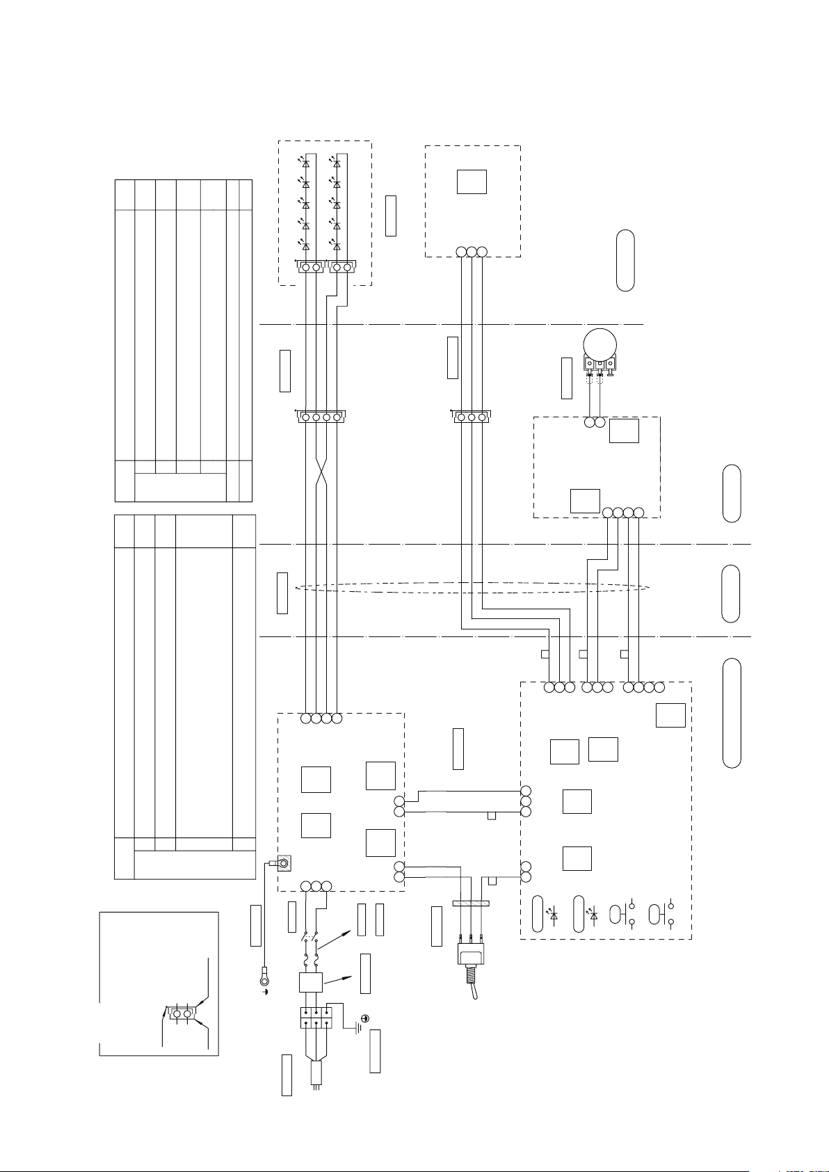
[3] WIRING DIAGRAM
CADQ74**
Earth line
CACP72**
Lead wire(Brown)100MM
CACP77**
Lead wire(Blue) 150MM
1A087M**
CADQ71**
Power cable (3200, SJT)
2-Fuse
250V/0.8A(T)
1A07X8**
5
9
CN9
JST
NH3P
4
10KB
3
1
312
SW2
1
SENSOR
MANUAL
6
L
N
SW1
PC
JP3
SW4
2
1
SW3
1
2
3
4
OFF
ON
ON
OFF
OFF
OFF
OFF
8
7
6
5
SW3
XA3P
XA4P
122
1
CN1
JST
EH3P
312
432
1
321
CN2
JST
XA2P
CN1
JST
PH4P
1
2
CN5
JST
XH4P
CN4
JST
XA3P
213
4
213
312
4
CN1
JST
XH3P
CN6
JST
NH2P
GND
CN201
JST
XH4P
CN202
JST
XH2P
CN204
JST
NH2P
CN101
JST
VH3P
4
213
312
2
1
1 2 3
1 2
21
AD10003NA
20110509
AL-901/902
OFF
PC
1A086X**
1A087L**
Lead wire for inside arm
(AL-901/902)
1A087K**
1A07M9**
Trunk line for LED sensor PCB
1A07MB**
1A07MA**
LED Module Assy.
1G027U**
Head Section
Sensor power input
Sensor output
GND
Yellow
Green
Blue
LED Sensor PCB.
SM2P(Black)
SM2P(Black)
LED module 1
LED module 2
Black
Black/White
Brown
Brown/White
(1G0280**)
Red
Orange
(VR) Intensity
adjustment
Intensity adjustment
Volume Section
Display LED PCB.
DC5V power input 1
Display LED input
DC5V output
VR input
Red
Orange
Gray
Purple
VR output
DC5V power input 2
York Section
(1G027Z**)
Yellow
Green
Blue
Yellow
Green
Blue
Black
Black/White
Brown
Brown/White
Black
Black/White
Brown
Brown/White
Trunk line for LED module(Head)
Arm Section
Power Supply Box Section
GND
Sensor power
output
Sensor input
DC5V power output 2
Display LED output
Yellow
Green
Blue
Gray
Purple
Red
Orange
DC5V power
output 1
VR input
LED Light Control PCB.
(1G02A0**)
Power LED
Sensor Signal LED
LED2:Yellow
LED1:Green
Manual SW for
operation test
PWM output
Light Blue
White
Black
+
-
Pink
Light Blue
Bright Green
VR lower limit
setting
Ferrite
(Four turns)
LED output A1
LED output A2
LED output K1
LED output K2
Black
Black/White
Brown
Brown/White
LED Light Power PCB.
(1G028U**)
Sensor/Manual
Mode Selection Switch
+
-
DC5V
Power input
Black
White
Pink
Bright Green
DC5V
Power input
AC120V
Power Input
PWM input
Power Switch
Terminal Block
Green/Yellow
Light Blue
Green/Yellow
Remarks
Connector Symbol
SM ... SM Connector
XA ... XA Connector
Plug
The side with black dot
has male pins
Receptacle
Black dot
Setting condition
Transition time to Composite mode (by a sensor)
O: 1 second, On: 2 seconds
Combining dental unit
O: Clair unit, On: CP-One plus
Settings of PCB dip switches ( SW3,4) and jumper pin (JP3).
Default
setting
Setting condition
Sensor activation setting
O: Activate when a hand goes away, On: Activate when a hand comes in.
6 Includes Composite Mode
O:Yes, On: No
Speed setting of communication line
O: 4800bps, On: 2400bps
LED blink setting of Composite Mode
O: Slow blinking, On: Rapid blinking
PC side: Clair Unit, 232 side: CP-One plus
PC side: Clair Unit, 232 side: CP-One plus
Default
setting
Earth line for power PCB.
Trunk line for power PCB.
Green
Test mode ( Always OFF)
O: Normal operation, On: Test operation
Trunk line for Control PCB.power
Blue
Blue
Brown
Brown
Noise filter section(AL-901)
1A08AH**
2
1
3
4
Brown
Wake-up brightness setting from light o condition.
O : 1. Composite Mode when a light is turned on by using a sensor.
: 2. Keeps on getting on/o signal from dr table, light stays in composite mode.
On : 1. Regular Mode when a light is turned on by using a sensor.
: 2. Keeps on getting on/o signal from dr table, light goes into regular mode.
3-1. Unit Mount (AL-901) & Ceiling Mount (AL-902)
- 2 -
Page 7
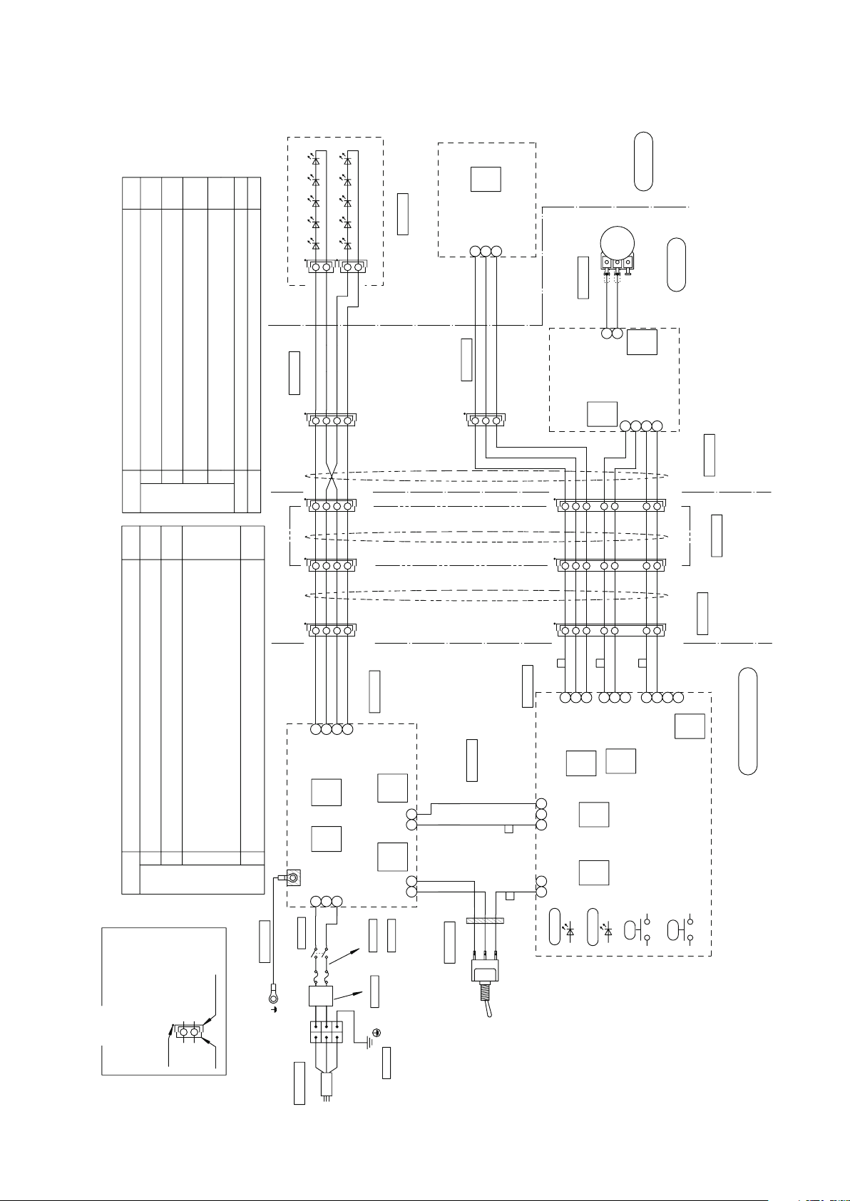
3-2. Track Mount (AL-905)
1A087T**
1A087S**
1A087R**
1A087Q**
1A087P**
XM4P
123
44
321
XM4P
XM4P
123
4
XA7P
321
4
5
6
77
6
5
4
123
XA7PXA7P
321
4
5
6
7
CACP76**
CACP77**
1A087N**
1A08AJ**
1A087M**
CAMV01**
1A07X8**
5
9
CN9
JST
NH3P
4
10KB
3
1
312
SW2
1
SENSOR
MANUAL
6
L
N
SW1
JP3
SW4
2
1
SW3
1
2
3
4
OFF
ON
ON
OFF
OFF
OFF
OFF
8
7
6
5
SW3
XA3P
XA4P
122
1
CN1
JST
EH3P
312
432
1
321
CN2
JST
XA2P
CN1
JST
PH4P
1
2
CN5
JST
XH4P
CN4
JST
XA3P
213
4
213
312
4
CN1
JST
XH3P
CN6
JST
NH2P
CN201
JST
XH4P
CN202
JST
XH2P
CN204
JST
NH2P
CN101
JST
VH3P
4
213
312
21
1 2 3
1 2
21
AD10003PA
20110509
AL-905
OFF
1A086X**
1A087L**
1A07M9**
1A07MB**
1A07MA**
1G027U**
LED Module Assy.
SM2P(Black)
SM2P(Black)
LED module 1
LED module 2
Black
Black/White
Brown
Brown/White
Sensor power input
Sensor output
GND
Yellow
Green
Blue
LED Sensor PCB.
(1G0280**)
Head Section
Red
Orange
(VR) Intensity
adjustment
Intensity adjustment
Volume Section
York Section
Display LED PCB.
DC5V power input 1
Display LED input
DC5V output
VR input
Red
Orange
Gray
Purple
VR output
DC5V power input 2
(1G027Z**)
Trunk line for LED sensor PCB
Yellow
Green
Blue
Yellow
Green
Blue
Black
Black/White
Brown
Brown/White
Trunk line for LED module(Head)
Black
Black/White
Brown
Brown/White
Black
Black/White
Brown
Brown/White
Black
Black/White
Brown
Brown/White
Black
Black/White
Brown
Black
Black/White
Brown
Brown/White
Brown/White
Trunk line for LED module
Trunk line for Control PCB. power
LED output A1
LED output A2
LED output K1
LED output K2
Power LED
Sensor Signal LED
LED2:Yellow
LED1:Green
Manual SW for
operation test
PWM output
+
-
VR lower limit
setting
DC5V
Power input
GND
Sensor power
output
Sensor input
DC5V power output 2
Display LED output
DC5V power
output 1
VR input
Light Blue
White
Black
Pink
Light Blue
Bright Green
Ferrite
(Four turns)
Sensor/Manual
Mode Selection Switch
Black
White
Pink
Bright Green
GND
+
-
DC5V
Power input
PWM input
Earth line 500mm
Power cable (500mm)
2-Fuse
250V/0.8A(T)
Power Switch
Terminal Block
Lead wire(Blue) 150MM
Lead wire(Brown)150MM
Green/Yellow
Light Blue
Brown
Green/Yellow
Trunk line for power PCB.
Blue
Brown
LED Light Power PCB.
(1G028U**)
AC120V
Power Input
Yellow
Green
Blue
Gray
Purple
Red
Orange
Yellow
Green
Blue
Gray
Purple
Red
Orange
Yellow
Green
Blue
Gray
Purple
Red
Orange
Yellow
Green
Blue
Gray
Purple
Red
Orange
Trunk line B for power supply box
Trunk line A for
power supply box
Trunk line C for power supply box
(Pole size 8.5 ~ 10F)
Power Supply Box Section
Remarks
Connector Symbol
SM ... SM Connector
XA ... XA Connector
Plug
The side with black dot
has male pins
Receptacle
Black dot
XM ... XM Connector
Earth line for power PCB.
Green
Setting condition
Transition time to Composite mode (by a sensor)
O: 1 second, On: 2 seconds
Combining dental unit
O: Clair unit, On: CP-One plus
Settings of PCB dip switches ( SW3,4) and jumper pin (JP3).
Default
setting
Setting condition
Sensor activation setting
O: Activate when a hand goes away, On: Activate when a hand comes in.
6 Includes Composite Mode
O:Yes, On: No
Speed setting of communication line
O: 4800bps, On: 2400bps
LED blink setting of Composite Mode
O: Slow blinking, On: Rapid blinking
PC side: Clair Unit, 232 side: CP-One plus
PC side: Clair Unit, 232 side: CP-One plus
Default
setting
Test mode (Always OFF)
O: Normal operation, On: Test operation
PC
PC
Trunk line for Signal
LED Light Control PCB.
(1G02A0**)
Blue
2
1
3
4
Brown
Noise filter section(AL-905)
Wake-up brightness setting from light o condition.
O : 1. Composite Mode when a light is turned on by using a sensor.
: 2. Keeps on getting on/o signal from dr table, light stays in composite mode.
On : 1. Regular Mode when a light is turned on by using a sensor.
: 2. Keeps on getting on/o signal from dr table, light goes into regular mode.
- 3 -
Page 8
1G027U**
1A07MA**
1A07MB**
1A07M9**
1A087S**
1A09GV**
1A07MR**
XA3P
123
1 2
21
321
1 2
213
312
4
CN101
JST
VH3P
CN204
JST
NH2P
CN202
JST
XH2P
CN201
JST
XH4P
CN6
JST
NH2P
CN1
JST
XH3P
4
213
312
4
312
CN4
JST
XA3P
CN5
JST
XH4P
2
1
CN1
JST
PH4P
CN2
JST
XA2P
123
123
4
213
CN1
JST
EH3P
1
221
XA4P
XA3P
SW1
N
L
6
MANUAL
SENSOR
1
SW2
213
1
3
10KB
4
CN9
JST
NH3P
9
5
1A07X8**
7
6
5
4
123
XA7P
XM4P
432
1 1
234
XM4P
1A09GU**
321
21
XM2P
XM3P
1 2 3
1A07MP**
1A07MM**
1A07MQ**
1A0AP2**
XA3P
LED Module Assy.
SM2P(Black)
SM2P(Black)
LED module 1
LED module 2
Black
Black/White
Brown
Brown/White
Sensor power input
Sensor output
GND
Yellow
Green
Blue
LED Sensor PCB.
(1G0280**)
Black
Black/White
Brown
Brown/White
Black
Black/White
Brown
Brown/White
Trunk line for LED module(Head)
Trunk line for LED sensor PCB
Yellow
Green
Blue
Yellow
Green
Blue
Head Section
Red
Orange
(VR) Intensity
adjustment
Intensity adjustment
Volume Section
DC5V power input 1
Display LED input
DC5V output
VR input
Red
Orange
Gray
Purple
VR output
DC5V power input 2
Yellow
Green
Blue
Gray
Purple
Red
Orange
Yellow
Green
Blue
Red
Orange
Gray
Purple
GND
Sensor power
output
Sensor input
DC5V power output 2
Display LED output
DC5V power
output 1
VR input
PWM output
+
-
DC5V
Power input
White
Black
LED Light Control PCB.
(1G02A0**)
Power LED
Sensor Signal LED
LED2:Yellow
LED1:Green
Manual SW for
operation test
VR lower limit
setting
Light Blue
LED output A1
LED output A2
LED output K1
LED output K2
Black
Black/White
Brown
Brown/White
Black
Black/White
Brown
Brown/White
Black
Black/White
Brown
Brown/White
Trunk line for LED module(Power)
GND
+
-
DC5V
Power output
AC120V
Power Input
PWM input
Black
White
Pink
Bright Green
Trunk line A for mode
selection sw
Power line A for control
PCB (AL-900)
Power line B for control
PCB (DL-900)
Trunk line for mode
selection sw (AL-907)
York Section
Pole Section
Power Supply Box Section
Trunk line A between power
supply box - yoke (AL-907)
Trunk line B between power
supply box - yoke
LED Light Power PCB.
(1G028U**)
Green
Earth line for power PCB.
Pink
Light Blue
Bright Green
Pink
Light Blue
Bright Green
Ferrite
(Four turns)
Sensor/Manual
Mode Selection Switch (AL-907)
Power Panel Section
PC
JP3
SW4
SW3
1
2
3
4
OFF
ON
ON
OFF
OFF
OFF
OFF
8
7
6
5
SW3
OFF
PC
Setting condition
Transition time to Composite mode (by a sensor)
O: 1 second, On: 2 seconds
Combining dental unit
O: Clair unit, On: CP-One plus
Settings of PCB dip switches ( SW3,4) and jumper pin (JP3).
Default
setting
Setting condition
Sensor activation setting
O: Activate when a hand goes away, On: Activate when a hand comes in.
6 Includes Composite Mode
O:Yes, On: No
Speed setting of communication line
O: 4800bps, On: 2400bps
LED blink setting of Composite Mode
O: Slow blinking, On: Rapid blinking
PC side: Clair Unit, 232 side: CP-One plus
PC side: Clair Unit, 232 side: CP-One plus
Default
setting
Test mode ( Always OFF)
O: Normal operation, On: Test operation
Wake-up brightness setting from light o condition.
O : 1. Composite Mode when a light is turned on by using a sensor.
: 2. Keeps on getting on/o signal from dr table, light stays in composite mode.
On : 1. Regular Mode when a light is turned on by using a sensor.
: 2. Keeps on getting on/o signal from dr table, light goes into regular mode.
Display LED PCB.
(1G027Z**)
1
2
Remarks
Connector Symbol
SM ... SM Connector
XA ... XA Connector
XM... XM Connector
Plug Receptacle
The side with black dot
has male pins
Black dot
1A078N**
250V/0.8A(T)
2
1
3
4
CACP77**
1A09GR**
CACP76**
L
N
1A09GW**
AC120V
Power
Trunk line for power PCB.
(AL-907)
Noise filter section
(AL-907)
(Green/Yellow)
(Light Blue)
(Brown)
Green/Yellow
Power switch
Blue
Brown
Blue
Brown
Blue
Brown
Blue
Brown
Blue
Brown
Blue
Brown
Lead Wire Blue
150 MM
Lead Wire Brown
150 MM
Earth 500MM
Remarks:
Power lines must be prepared
at the installation site.
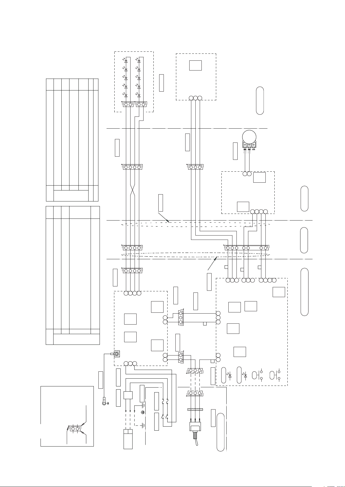
3-3. Cabinet Mount (AL-907)
- 4 -
Page 9
1G027U**
1A07MA**
1A07MB**
1A07M9**
1A087S**
1A09GK**
1A07MR**
1 2
21
321
1 2
213
312
4
CN101
JST
VH3P
CN204
JST
NH2P
CN202
JST
XH2P
CN201
JST
XH4P
CN6
JST
NH2P
CN1
JST
XH3P
4
213
312
4
312
CN4
JST
XA3P
CN5
JST
XH4P
2
1
CN1
JST
PH4P
CN2
JST
XA2P
123
123
4
213
CN1
JST
EH3P
1
221
XA4P
XA3P
1
2
SW1
N
L
6
MANUAL
SENSOR
1
SW2
213
1
3
10KB
4
CN9
JST
NH3P
9
5
1A07X8**
2
1
3
4
1A04CZ**
7
6
5
4
123
XA7P
XM4P
432
1 1
234
XM4P
1A09GN**
321
1A09GM**
1A09GL**
XA3P
LED Module Assy.
SM2P(Black)
SM2P(Black)
LED module 1
LED module 2
Black
Black/White
Brown
Brown/White
Sensor power input
Sensor output
GND
Yellow
Green
Blue
LED Sensor PCB.
(1G0280**)
Black
Black/White
Brown
Brown/White
Black
Black/White
Brown
Brown/White
Trunk line for LED module(Head)
Trunk line for LED sensor PCB
Yellow
Green
Blue
Yellow
Green
Blue
Head Section
Red
Orange
(VR) Intensity
adjustment
Intensity adjustment
Volume Section
DC5V power input 1
Display LED input
DC5V output
VR input
Red
Orange
Gray
Purple
VR output
DC5V power input 2
Yellow
Green
Blue
Gray
Purple
Red
Orange
Yellow
Green
Blue
Red
Orange
Gray
Purple
GND
Sensor power
output
Sensor input
DC5V power output 2
Display LED output
DC5V power
output 1
VR input
PWM output
+
-
DC5V
Power input
White
Black
LED Light Control PCB.
(1G02A0**)
Power LED
Sensor Signal LED
LED2:Yellow
LED1:Green
Manual SW for
operation test
VR lower limit
setting
Light Blue
LED output A1
LED output A2
LED output K1
LED output K2
Black
Black/White
Brown
Brown/White
Black
Black/White
Brown
Brown/White
Black
Black/White
Brown
Brown/White
Trunk line for LED module(Power)
GND
+
-
DC5V
Power output
AC120V
Power Input
PWM input
Black
White
Pink
Bright Green
Power line for
control PCB
Trunk line B for mode
selection sw
York Section
Pole Section
Power Supply Box Section
Trunk line A between power
supply box - yoke
Trunk line B between power
supply box - yoke
White
Black
Terminal Block
Blue
Brown
Green/Yellow
Green/Yellow
Light Blue
Brown
CT Code 2000L
LED Light Power PCB.
(1G028U**)
Green
Earth line for power PCB.
Pink
Light Blue
Bright Green
Ferrite
(Four turns)
Sensor/Manual
Mode Selection Switch
Cover Section
PC
JP3
SW4
SW3
1
2
3
4
OFF
ON
ON
OFF
OFF
OFF
OFF
8
7
6
5
SW3
OFF
PC
Setting condition
Transition time to Composite mode (by a sensor)
O: 1 second, On: 2 seconds
Combining dental unit
O: Clair unit, On: CP-One plus
Settings of PCB dip switches ( SW3,4) and jumper pin (JP3).
Default
setting
Setting condition
Sensor activation setting
O: Activate when a hand goes away, On: Activate when a hand comes in.
6 Includes Composite Mode
O:Yes, On: No
Speed setting of communication line
O: 4800bps, On: 2400bps
LED blink setting of Composite Mode
O: Slow blinking, On: Rapid blinking
PC side: Clair Unit, 232 side: CP-One plus
PC side: Clair Unit, 232 side: CP-One plus
Default
setting
Test mode ( Always OFF)
O: Normal operation, On: Test operation
Wake-up brightness setting from light o condition.
O : 1. Composite Mode when a light is turned on by using a sensor.
: 2. Keeps on getting on/o signal from dr table, light stays in composite mode.
On : 1. Regular Mode when a light is turned on by using a sensor.
: 2. Keeps on getting on/o signal from dr table, light goes into regular mode.
Remarks
Connector Symbol
SM ... SM Connector
XA ... XA Connector
XM... XM Connector
VL... VL Connector
Plug Receptacle
Display LED PCB.
(1G027Z**)
123
4
VL4P
Pink
Light Blue
2-Fuse
250V/0.8A(T)
Brown
Blue
Black
White
Blue
Black
White
Brown
Trunk line for fuse
1A09GJ**
1A04CX**
Earth line 200L
1A09GH**
Noise filter section
The side with black dot
has male pins
Black dot
OFF
Blue
Brown
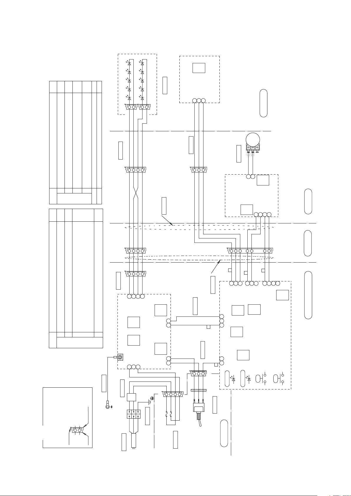
3-4. Wall Mount (AL-908)
- 5 -
Page 10
2
1
3
4
1A08AJ**
1A08CH**
XA2P
XA8P
123
4
1A08CE**
Trunk line for fuse-air sw (L)
(920X)
CADQ74**
1A08CG**
1A04D6**
1A07X8**
5
9
CN9
JST
NH3P
4
10KB
3
1
312
SW2
1
SENSOR
MANUAL
6
L
N
SW1
PC
JP3
SW4
2
1
SW3
1
2
3
4
OFF
ON
ON
OFF
OFF
OFF
OFF
8
7
6
5
SW3
XA3P
XA4P
122
1
CN1
JST
EH3P
312
432
1
321
CN2
JST
XA2P
1
2
CN5
JST
XH4P
CN4
JST
XA3P
213
4
213
312
4
CN1
JST
XH3P
CN6
JST
NH2P
CN201
JST
XH4P
CN202
JST
XH2P
CN204
JST
NH2P
CN101
JST
VH3P
4
2133
1
2
1 2 321
AD10003TA
AL-920X
OFF
PC
1A089U**
1A07M9**
1A07MB**
1A07MA**
1A089T**
1
221
567
8
XA4P
123
4
1A089V**
OFF
Trunk line for fuse-air sw (N)
(920X)
1A08CF**
1G027U**
LED Module Assy.
SM2P(Black)
SM2P(Black)
LED module 1
LED module 2
Black
Black/White
Brown
Brown/White
Sensor power input
Sensor output
GND
Yellow
Green
Blue
LED Sensor PCB.
(1G0280**)
Head Section
York Section
Red
Orange
(VR) Intensity
Adjustment
Intensity adjustment
Volume Section
CN1
JST
PH4P
Display LED PCB.(DL-900)
DC5V output
VR input
(1G027Z**)
DC5V power input 1
Display LED input
Red
Orange
Gray
Purple
VR output
DC5V power input 2
Trunk line for LED sensor PCB
Yellow
Green
Blue
Yellow
Green
Blue
Black
Black/White
Brown
Brown/White
Black
Black/White
Brown
Brown/White
Trunk line for LED module(Head)
Yellow
Green
Blue
Gray
Purple
Red
Orange
Sensor power
output
Sensor input
DC5V power output 2
Display LED output
DC5V power
output 1
VR input
GND
Power LED
Sensor Signal LED
LED2:Yellow
LED1:Green
Manual SW for
operation test
VR lower limit
setting
LED Light Control PCB.
(1G02A0**)
PWM output
DC5V
Power input
+
-
White
Black
Light Blue
Pink
Bright Green
Black
White
Green
Blue
Purple
Gray
Bright Green
Pink
Light Blue
Lead wire line for S/M select sw
(with sw.)
Ferrite
Four turns
Inside arm lead wire
(AL-920X)
LED output A1
LED output A2
LED output K1
LED output K2
Black
Black/White
Brown
Brown/White
Brown
Red
Orange
Yellow
Green
Blue
Purple
Gray
Brown
Red
Orange
Yellow
Green
Blue
Purple
Gray
Power PCB. signal line
(AL-920X)
LED Light Power PCB.
(DL-900)
(1G028U**)
Light Blue
Brown
Green/Yellow
2-Fuse
250V/0.8A(T)
Remarks
Connector Symbol
SM ... SM Connector
XA .. . XA Connector
XM ... XM Connector
Plug
The side with black dot
has male pins
Receptacle
Black dot
Brown
Blue
Brown
Air Switch
Blue
Blue
Brown
AC120V
Power Input
Noise filter section
(AL-905)
Green/Yellow
Earth line (701M)
Power supply cable 1000L
Earth line for power PCB.
Green
Trunk line for
air sw - power pcb.
DC5V
Power output
+
-
GND
PWM input
Trunk line for AL-920X
(inside duct hose)
Switch box Section
Power supply box Section
Setting condition
Transition time to Composite mode (by a sensor)
O: 1 second, On: 2 seconds
Combining dental unit
O: Clair unit, On: CP-One plus
Settings of PCB dip switches ( SW3,4) and jumper pin (JP3).
Test mode ( Always OFF)
O: Normal operation, On: Test operation
Default
setting
Setting condition
Sensor activation setting
O: Activate when a hand goes away, On: Activate when a hand comes in.
6 Includes Composite Mode
O:Yes, On: No
Speed setting of communication line
O: 4800bps, On: 2400bps
LED blink setting of Composite Mode
O: Slow blinking, On: Rapid blinking
PC side: Clair Unit, 232 side: CP-One plus
PC side: Clair Unit, 232 side: CP-One plus
Default
setting
Wake-up brightness setting from light o condition.
O : 1. Composite Mode when a light is turned on by using a sensor.
: 2. Keeps on getting on/o signal from dr table, light stays in composite mode.
On : 1. Regular Mode when a light is turned on by using a sensor.
: 2. Keeps on getting on/o signal from dr table, light goes into regular mode.
2
1
XA2P
2
1
Brown
Red
Yellow
Orange
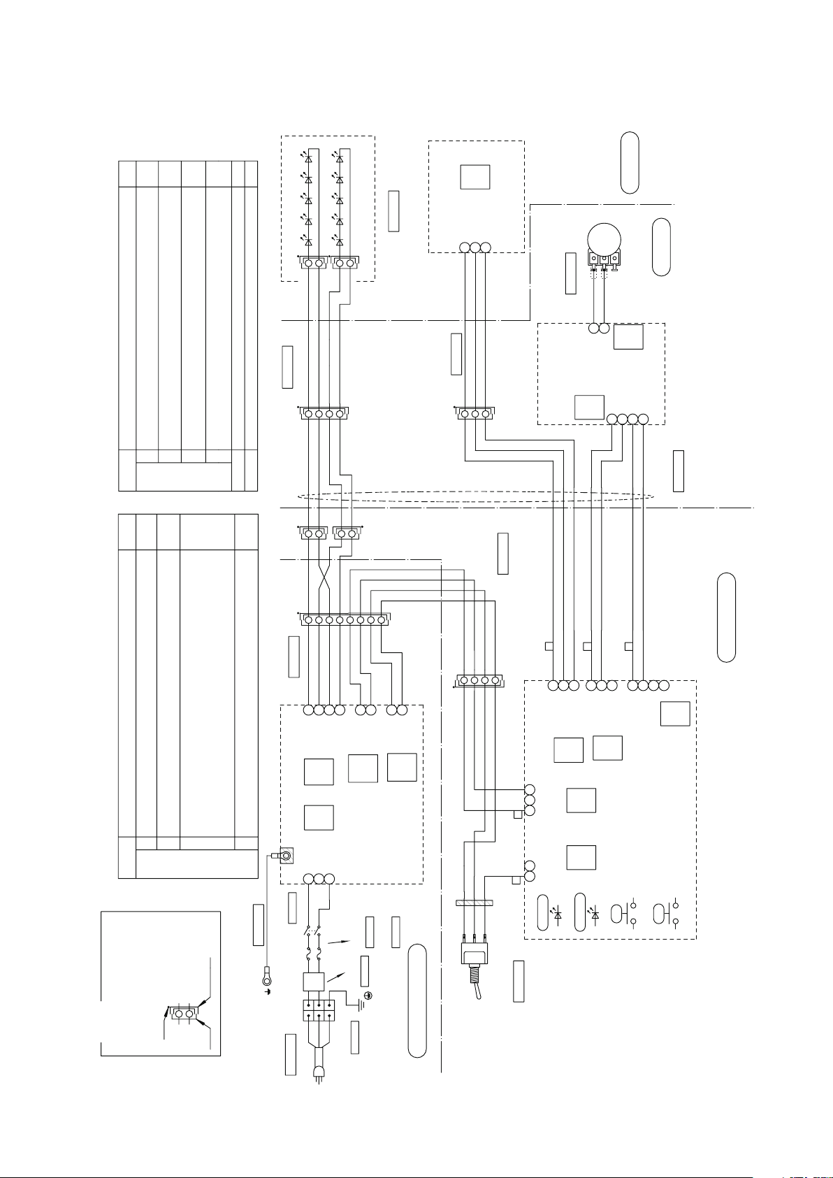
3-5. Swing Mount (AL-920X)
- 6 -
Page 11
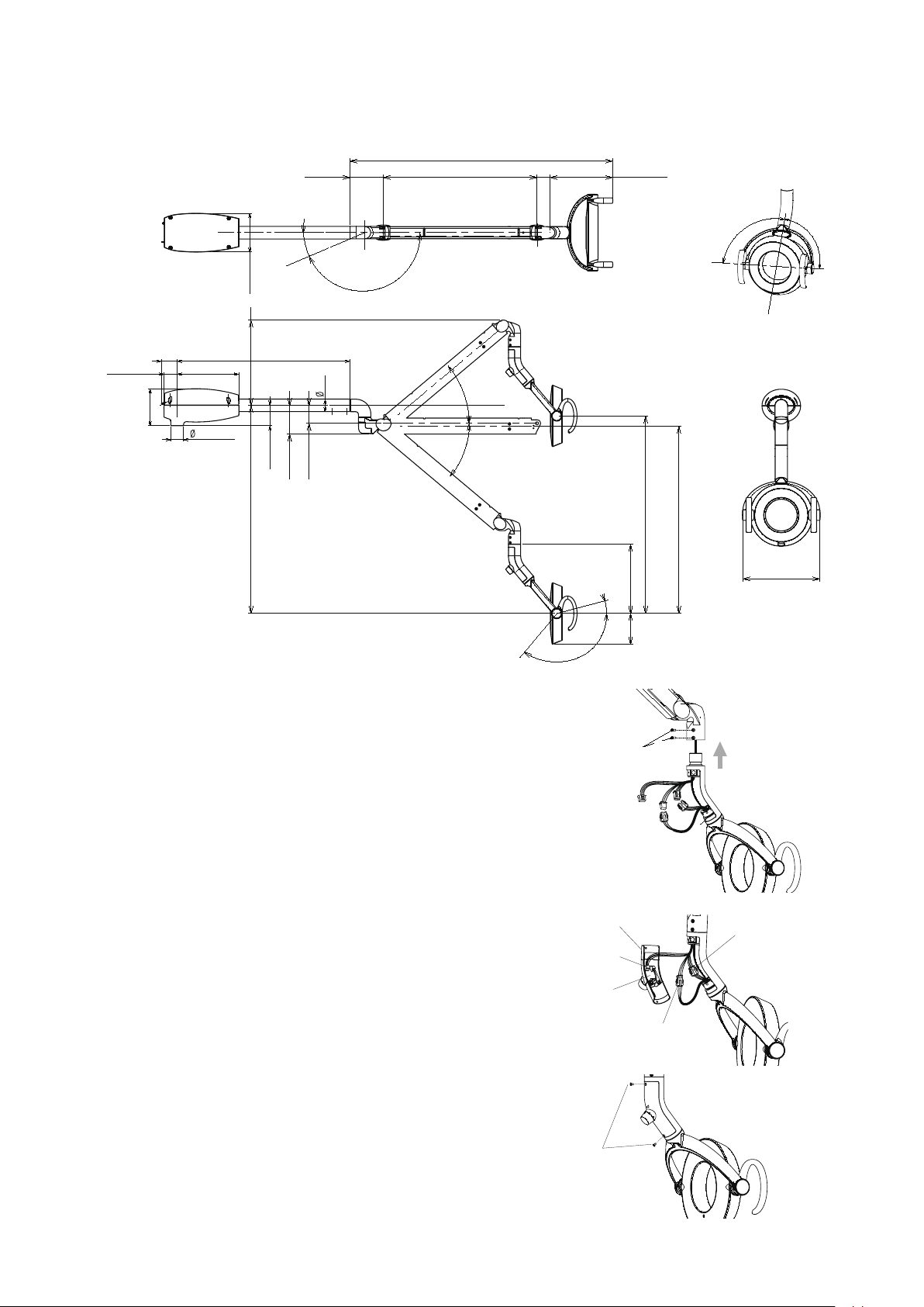
Dimentsion (AL-911)
4-3/16” (106)
11-9/16” (294)28-1/4” (718)
3-7/8” (98)
2-7/16” (62)
26-13/16” (681)
25-7/16” (646)
9-3/8” (238.5)
10-7/16” (265)
35-11/16” (906)
8-7/16” (214.5)1-13/16 (46.5)20-7/8” (530)
4-1/2” (115)
4-15/16” (126)
2-1/8” (54) 23-3/16” (588.5)
1-11/16” (42.7)
2-11/16(69)
1-11/16” (43)
1-3/4” (45)
8-1/4” (210)
5-3/16” (132)
29º
151º
40º
40º
130º
15º
Inch (mm)
90º
90º
M4 X 10
Painted Screw
Light Head
Balance Arm
3P Connector
4P Connector
Yoke Cover
LED Light
Display PCB.
4P Connector
M3 X 6
Painted Screw
INSTALLATION INSTRUCTIONS
[4] UNIT MOUNT TYPE (AL-901)
4-1. Dimensions
4-2. Installation Instructions
* All necessary parts are included in the box.
•M3 x 6 Painted Screw ......... 2pcs.
•M4 x 10 Painted Screw ....... 2pcs.
•Yoke Cover ..........................
1pce.
1) Install the light head to the balance arm
with M4 x 10 painted screws.
2) Connect the wire harness
3P connector : yellow / green / blue
4P connector : black / black & white / brown /
brown & white
Same color to be met at each side of connector
4P connector : red / orange / purple / gray
connec to LED Light display PCB of yoke cover.
3) Attach the yoke cover with M3 x 6 painted screws.
- 7 -
Page 12
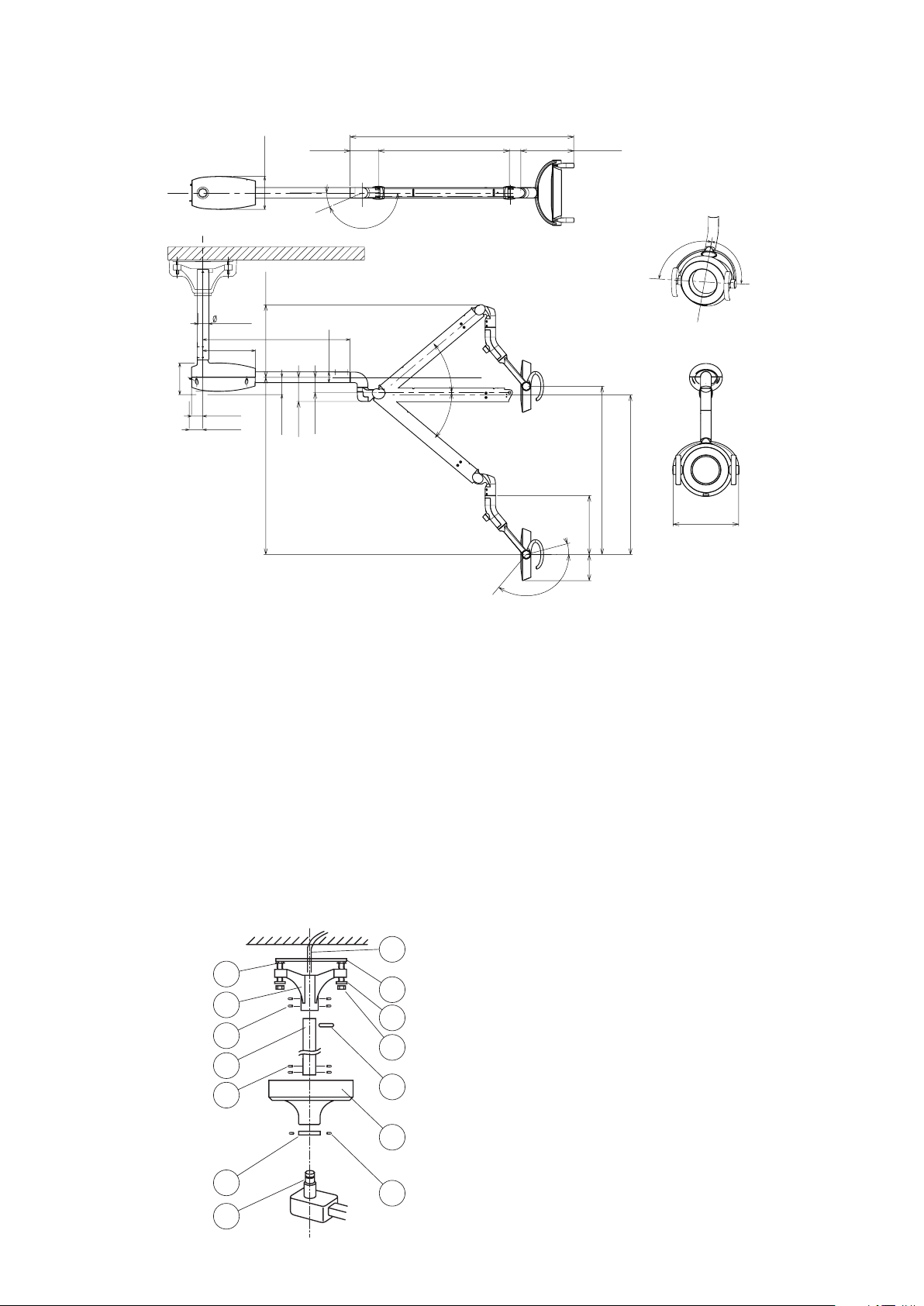
[5] CEILING MOUNT TYPE (AL-902)
4-1/2” (115)
5-3/16” (132)
29º
151º
20-7/8” (530)
35-11/16” (906)
8-7/16” (214.5)1-13/16 (46.5)
4-15/16” (126)
2-1/8” (54)
1-11/16” (43)
1-3/4” (45)
8-1/4” (210)
28-1/4” (718)
3-7/8” (98)
2-7/16” (62)
23-3/16” (588.5)
1-11/16” (42.7)
2-11/16(69)
11-9/16” (294)
40º
40º
4-3/16” (106)
26-13/16” (681)
25-7/16” (646)
9-3/8” (238.5)
130º
15º
10-7/16” (265)
Dimension (AL-912)
Inch(mm)
90º
90º
5
10
8
7
3
4
2
9
11
13
1
12
14
6
5-1. Dimensions
5-2. Installation Instructions
1) Secure mounting plate to the ceiling.
2) Route the power supply through the center of the mounting plate.
3) Install the leveling nuts between the mounting plate and the ceiling ange.
4) Install the ceiling ange to the mounting plate with washers and nuts supplied.
5) Insert the suspension tube into the ceiling ange and secure it with roll pin and set screws supplied.
6) Be sure the suspension tube is plumb.
7) Slide the ange cover and ange cover ring (at side up) over the suspension tube and secure them
about half way up the tube. Use only one set screw
8) Install the light assembly to the suspension tube running the 3 wire cord up through the tube to
the ceiling ange. Secure it with 4 Allen set screws.
9) Connect the incoming power to the 3 wire cord from the light assembly. Be sure to follow the local
electrical codes.
10) Test the light for proper operation.
11) Reposition the ange cover and secure it with the ange cover ring - Secure all set screws.
(2) Mounting Plate
(3) Leveling Nut
(4) Washer
(5) Nut
(6) Ceiling Flange
(7) Socket Screw for Flange
(8) Suspension Tube
(9) Roll Pin
(10) Socket Screw for Arm
(11) Flange Cover
(12) Cover Ring
(13) Socket Screw for Ring
(14) Suspension Tube of Arm
- 8 -
as you will be moving this on nal installation.
(1) Power Supply Cable
Page 13
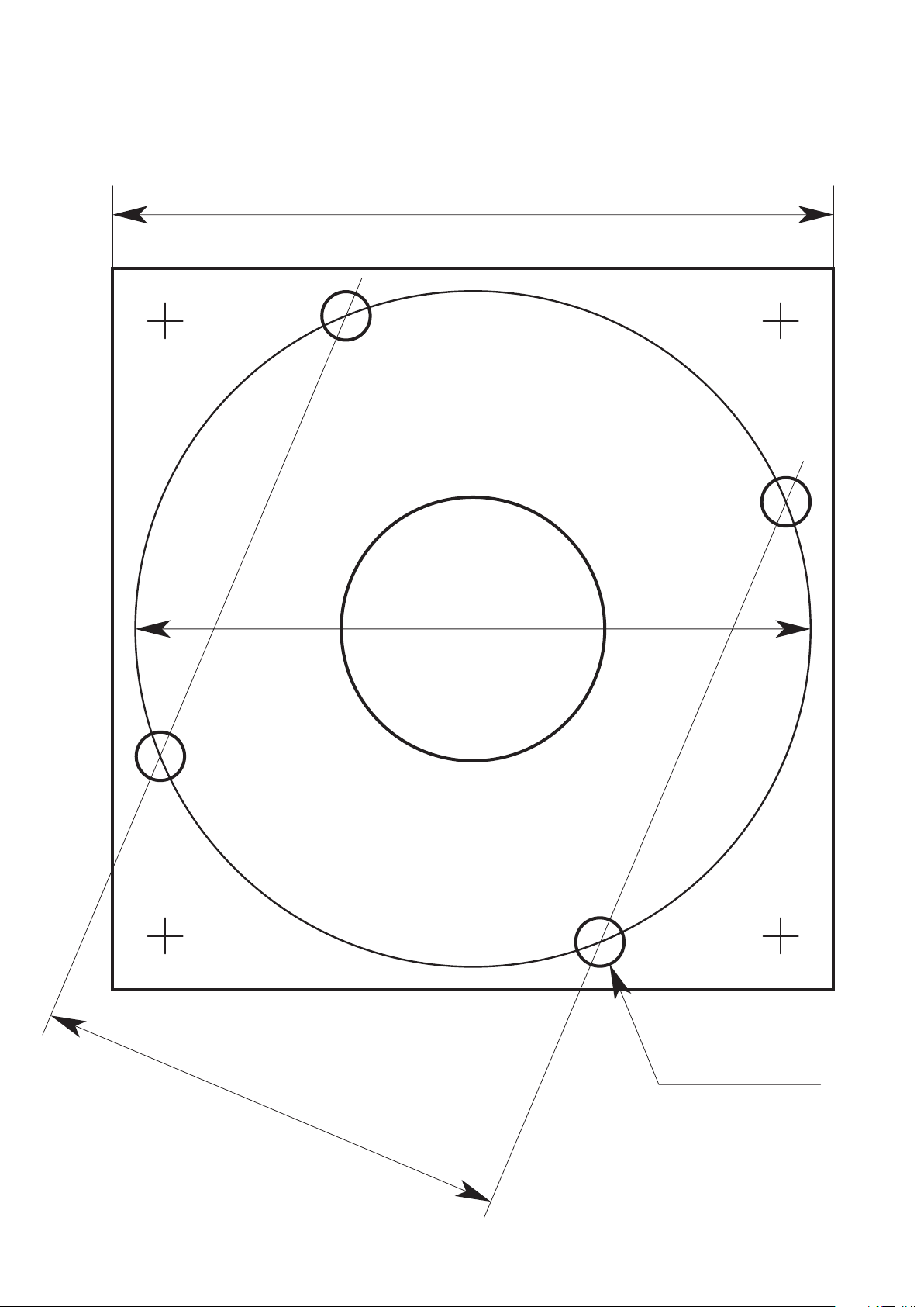
FULL-SIZE MOUNTING TEMPLATE
6"-1/16 (REF)
4"-9/32 (REF)
6"-15/32 (REF)
7/16"
Mounting Holes
- 9 -
Page 14
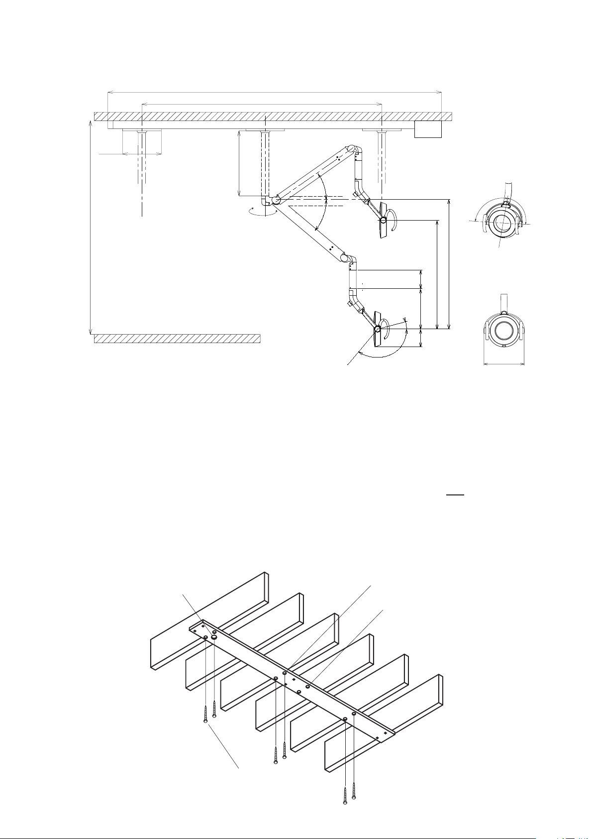
[6] TRACK MOUNT LIGHT (AL-905)
Electrical
Feed Opening
Transformer End
Used for 24" Center
to Center Joists
Used for 16" Cente
r
to Center Joists
5/16 x 3 Lag Bolts (6)
4-3/16” (106)
9-3/8” (238.5)
25-3/8” (644)
29-3/4” (756)
15” (380)
for 2400 mm ceiling height
39.5” (1000)
for 3000 mm ceiling height
Dimension (AL-915)
Inch (mm)
77-9/16” (1970)
57-1/16” (1450)
8-15/16” (227)
40°
35°
4-5/16” (110)
260º
90º
90º
10-7/16” (265)
130º
15º
94-1/2” (2400) - MAX 118” (3000)
6-1. Dimensions
6-2. Ceiling Preparation
For safety in operation as well as stability of the light source, the importance of proper ceiling
structure cannot be overemphasized. In general, a ceiling structure capable of supporting 200 lb.
dead weight is required.
A) In conventional ceilings with
by
at least
utilizing 16" or 12" cc ceiling joists. For other spacings or locations, additional holes can be cut
in pallet. (SEE FIGURE 1.)
IMPORTANT:
6 - 5/16 x 3" lag screws. Suitable holes are provided in pallet for most installations,
Locate transformer end of track at headrest end of chair. - Not legrest.
B) For conventional ceilings with
installed in 3 places to allow mounting with
joists perpendicular
joists parallel
at least
to the center line of the light, attach the pallet
to the center line of the light, cross blocks must be
6 - 5/16 x 3" lag screws. (SEE FIGURE 2.)
C) For suspended ceilings, appropriate rigid structure must be attached to the ceiling framework to
provide 200 lb. dead weight capacity. (SEE FIGURE 3.)
FIGURE 1
- 10 -
Page 15
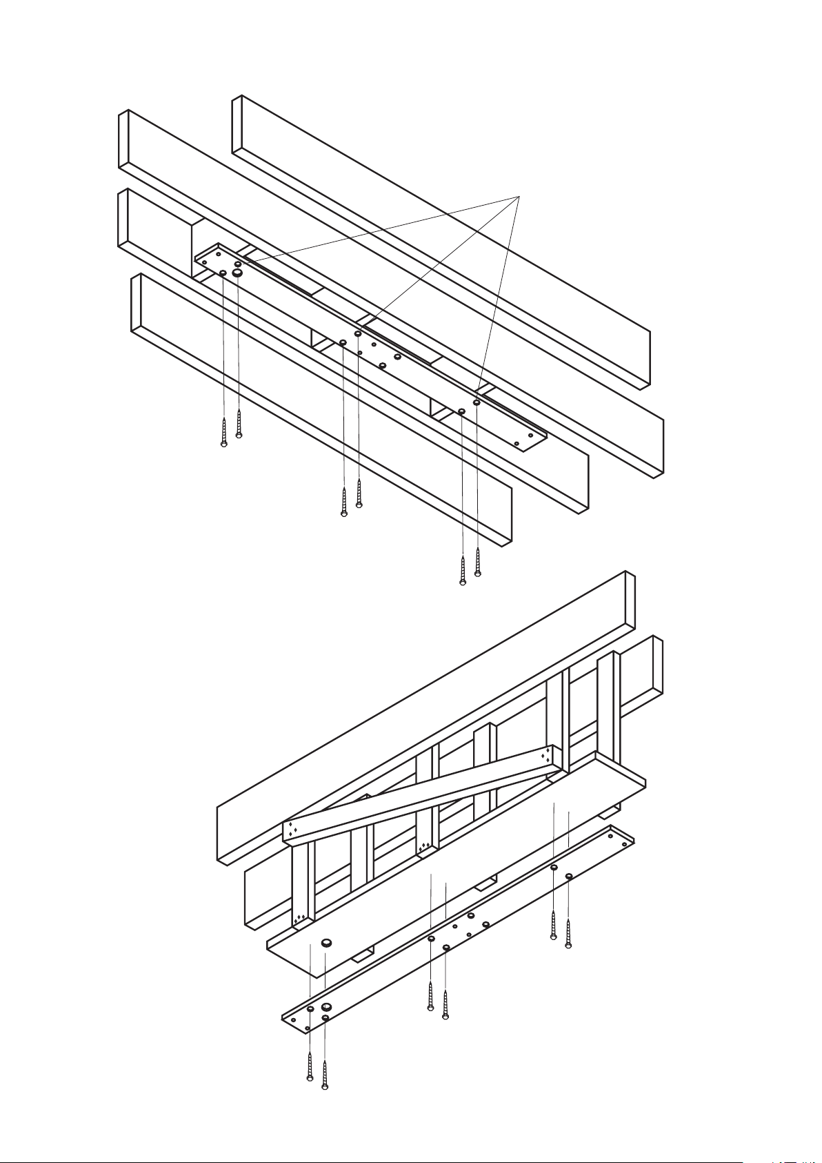
Crossblocks 3 Places
24" Center to Center
CEILING PREPARATION
FIGURE 2
- 11 -
FIGURE 3
Page 16
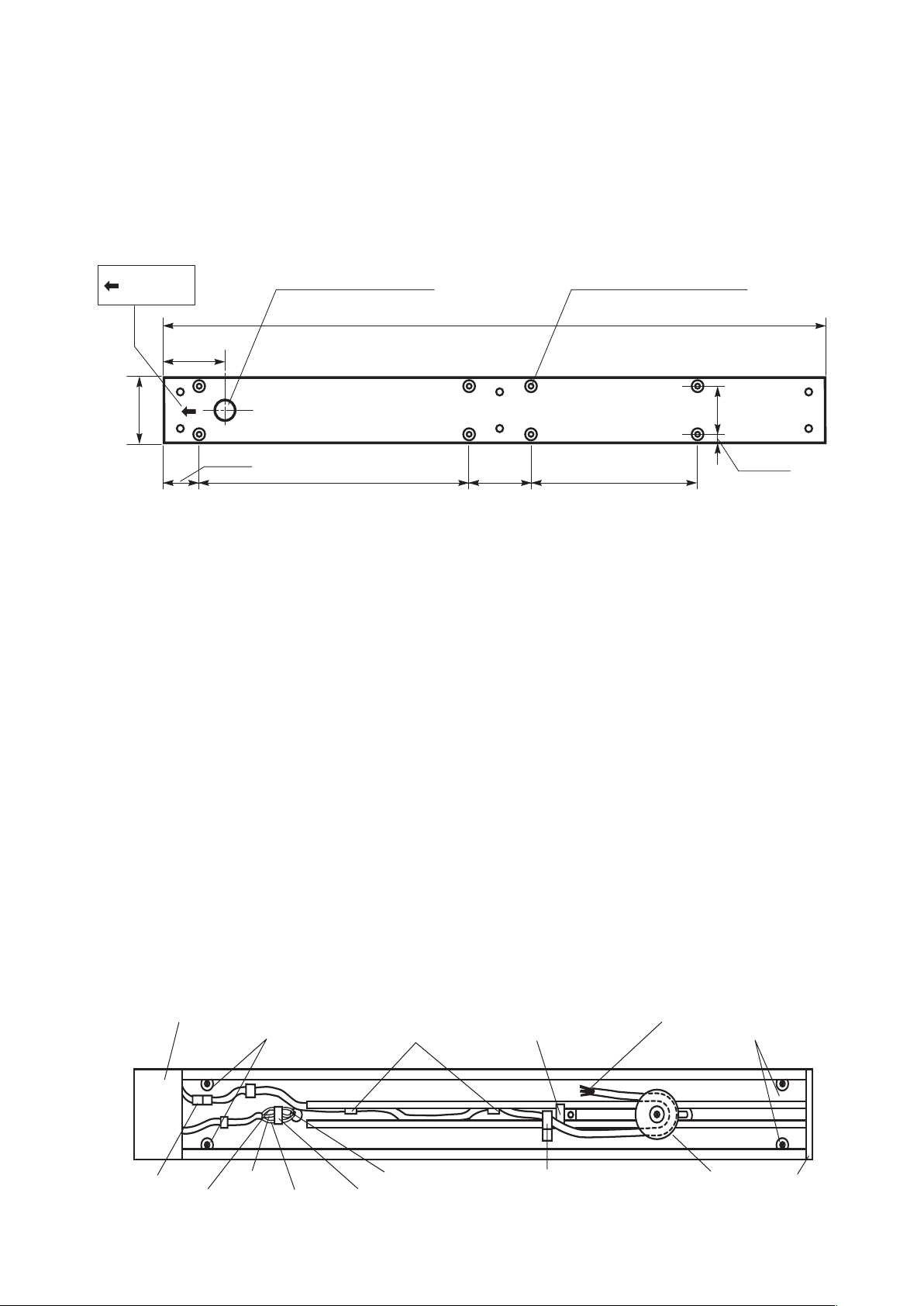
6-3. Electrical Preparation
Clamp (Factory
Installed on Wire)
Install Rubber
Bumpers after
Trolley
Connector
Green/Yellow
Brown
Light Blue
Transformer
Box
ElectricalFeed
Plastic
Wire Clip
Rubber
Bumpers
Pulley End Cap
Terminal Block
To Trolley
Z Clip
(Holds Bottom Cover)
6"-5/16
4"-1/4
24" 8" 16"
65"-1/4
11/16"
3"-5/85"
1"-5/8 DIA (Electrical
Feed Opening)
3/8" DIA HOLE
1" DIA C'Bore (8Holes)
Head of
Chair
Refer to
FIGURE 4
for the location of electrical feed opening in pallet, provide 3 wire, 120V, 60Hz
circuit (15 amp. fuse or breaker) through exible conduit with enough slack to protrude at least 2"
below the pallet when installed. Terminate the conduit with 1/2" body box connector suitable for
mounting through 3/16 thickness. A readily accessible shut-off switch for this circuit is recom-
mended. Use wiring suitable for 90˚C service.
FIGURE 4
6-4. Installation Instructions
1) Lead out the power supply cable from the ceiling where the track light is mounted.
2) Run the power supply cable through the pallet and mount the pallet.
3) Place track against the pallet and slightly engage two mounting bolts at the end opposite to the
electrical opening.
4) Allowing the free end to hang down slightly for access, install the conduit box connector
to the track.
5) Finish bolting the track securely to the pallet.
6) Connect the wires from the feed to the terminal block.
7) Slide the trolley onto the track (end near electrical opening) with the arrow on the trolley
oriented toward the pulley on the track.
8) Carefully guide the wire from the trolley, around the spring-loaded pulley and back toward the
end of track.
9) Attach retainer clamp to small screw in track. Clip the free end of the trolley wire into the plastic
clip near end.
10) Install rubber bumpers at the end of the track in the holes provided.
- 12 -
Page 17
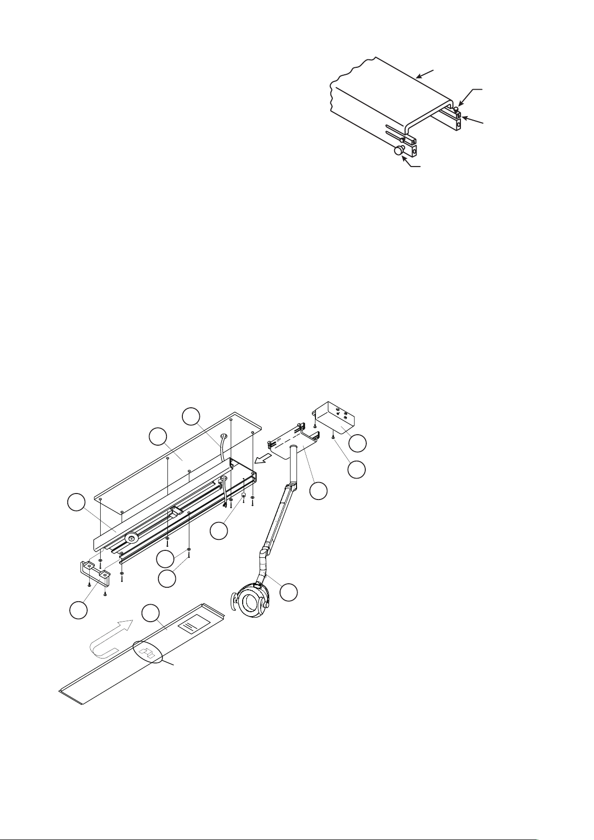
11) Check operation of the trolley. It is factory
Trolley
Adjustment
Screw
Rollers
Set Screw
1
2
3
4
12
8
11
9
6
5
10
7
DSL
This bracket is on the
rear side of the cover
adjusted to provide smooth effortless travel,
without play; however rollers can be
readjusted if necessary. Loosen the set screw
and adjust the socket cap screw to vary roller
clearance.
12) Unpack the transformer / housing assembly and mount it to the track with screws provided.
13) Attach the pigtail leads to the corresponding power line wires at the terminal block. Retain the
wires under the plastic clip.
14) Connect the plug-in connector to the trolley wire.
15) Carefully slide bottom cover onto the track from free end. Be sure to engage lip onto Z bracket.
16) Install the end-cap with the screws provided.
17) Slide the trolley back and forth, checking for binding or rubbing.
18) Conrm that the swing arm is properly adjusted to stay where it is placed. If necessary, move
the head up or down to expose the appropriate cross drilled nut and adjust with the tool
provided.
19) Turn on power and check electrical operation of the light.
(1) Power supply cable
(2) Pallet
(3) Track
(4) End-cup
(5) Trolley
(6) Power Supply Box
(7) Light Assembly
(8) Bottom Cover
(9) Rubber bumper
(10) Screw with plain washer &
spring washer M4x15(2 pcs)
(11) Hex Head Bolt M8x25(6 pcs)
(12) Spring Washer M8 (6 pcs)
- 13 -
Page 18
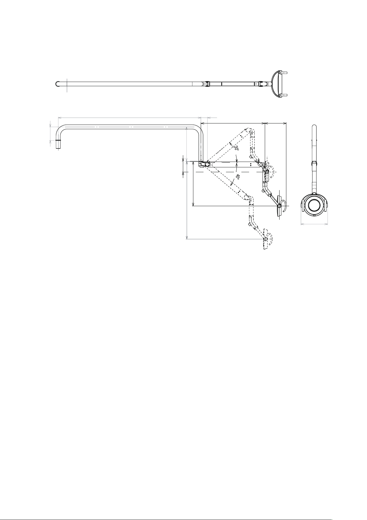
[7] CABINET MOUNT LIGHT (AL-907)
5-1/4” (135)
56” (1420)
2-1/2” (65)
25-1/4” (641.5)
8-1/2” (216)
13-1/2” (340)
4-1/4” (105)
31” (786)
17-1/2” (446)
10-7/16” (265)
7-1. Dimensions
7-2. Installation Instructions
Wiring diagram and installation instraction , See in cabinet installation manual.
- 14 -
Page 19
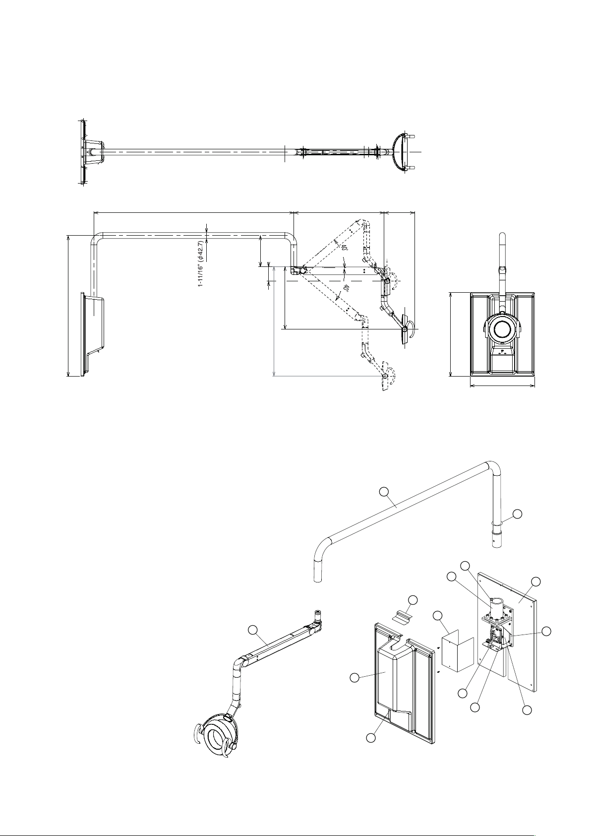
[8] WALL MOUNT LIGHT (AL-908)
56” (1420)
25-1/4” (641.5)
8-1/2” (216)
31” (786)
17-1/2” (446)
4-1/4” (105)
23-7/16” (596)
18” (456)
8-11/16” (220)
39-1/4” (998.9)
1
10
2
3
4
5
6
7
8
9
14
11
12
13
8-1. Dimensions
8-2. Over View and Major Components
(1) Light & Balance Arm Assembly
(2) Light Pole
(3) Pole Disc
(4) Wall Plate
(5) Wall Bracket
(6) Pole Receptacle
(7) Retainer Metal
(8) Power PCB. Box
(9) PCB. Bracket
(10) LED Light Control PCB.
(11) Bracket Cover
(12) Front Top Cover
(13) Fromt Cover
(14) Sensor/Manual Switch
- 15 -
Page 20
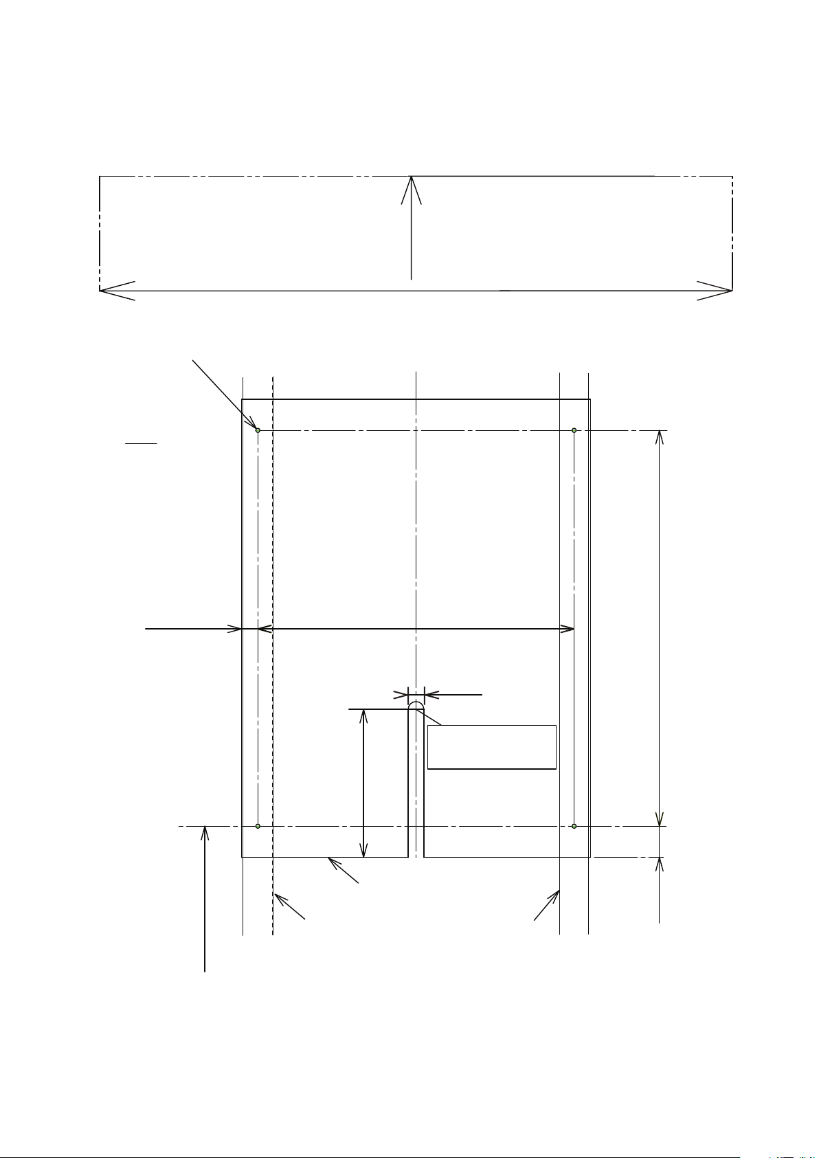
Maximum reach of light head from
Maximum reach of light head from
(inches)
mm
Location for Wires
(When internal power
source is used)
(13/16”)
(15-31/32”)
(25/32”)
(7-7/8”)
(1-9/16”)
(20”)
Ceiling height should be 2200(86-5/8) or higher
40 mm
21mm
406 mm
508 mm
200 mm
20 mm
AL-908 Wall Mount Light
Mounting plate pre-installation requirement
center is 2305mm (90-23/32”)
center is 2305mm (90-23/32”)
Drill four(4) pilot holes with 3/16” bit, depth of 2”
Wall stud
Wall stud
Mounting Plate
(49” From the floor)
1245 mm
- 16 -
Page 21
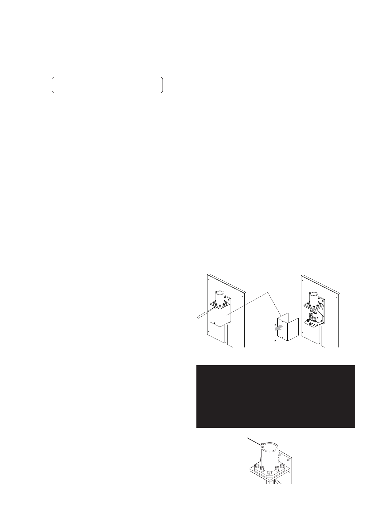
8-3. Pre INSTALLATION REQUIREMENT
Bracket Cover
Retainer metal
1) Mounting Location
The light backboard must be securely mounted to the wall studs.
DO NOT mount to metal studs.
2) Electrical Code Compliance
Conrm code requirements in your area.
3) Mounting to the backboard
1. A maximum of 71” to the top of the backboard from the oor.
2. A minimum of 8” from the top of the backboard to the ceiling.
3. It is important to locate the backboard no closer than 50” to the perpendicular wall.
4. The backboard should be approximately mid-line of the dental chair.
8-4. INSTALLATION
1) With a 3/16” drill bit, drill four (4) pilot holes approximately 2’ depth. See page 16.
2) Mount Wall Plate Assembly to the studs, with four (4) lag bolts and washers (Supplied).
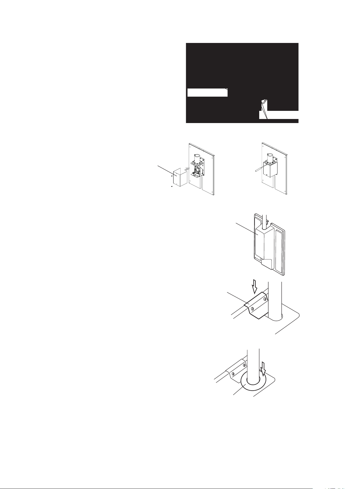
3) Remove Bracket Cover by removing two (2)
screws from it. This cover will be attached
later on.
4) Place a level on top of Pole Receptacle left to
right and front to back, and adjust the level with
four leveling bolts.
5) Remove the retainer metal from top of pole
receptacle .
(This metal must be installed later on)
- 17 -
Page 22
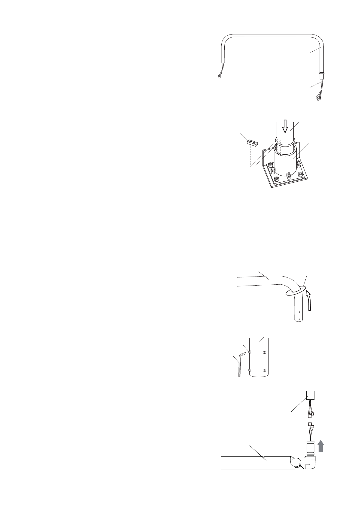
6) Light Pole Mounting
Light Pole
Wire
Light pole
Pole
Receptacle
Retainer Metal
Pole Disc
Light Pole
Light Pole
Set Screw
Allen Wrench
Balance Arm Assy
Light Pole
a) Insert the wires from the longer end of light
pole through light pole receptacle.
b) Mount light pole onto the receptacle. To make this job
easier, hold the ligth pole horizontally, and swing it right
and left while inserting into pole receptacle.
7) Re-attach retainer metal which was removed in step 5.
8) Connection of wiring
a. 4P connector (Black, Black/White, Brown, Brown/White)
from light pole to 4P connector from power pcb box.
b. 3P connector from light pole (Yellow, Green, Blue)
to CN4 on control pcb.
c. 3P connector from light pole (Red, Orange)
to CN9 on control pcb.
d. 4P connector (Purple, Gray) from light pole
to CN5 on control pcb.
9) Slide pole disc onto the light pole from the shorter
end of the pole.
10) Loosen four (4) set screws on the light pole
(DO NOT remove set screws).
11) Attach ligth and balance arm assembly to ligth pole :
a. Join connectors (4P & 7P) from light poie to those from
balance arm.
b. Insert balance arm stem into ligth pole.(If wires stick,
pull wires from wall bracket inside)
c. Tighten four (4) set screws loosened in step 10. These
screws also limit the swing range of balance arm.
- 18 -
Page 23
Front Cover
3P and 4P Connectors
12) Connect power supply cable to proper source.
Bracket Cover
Front Cover
Front Top Cover
Pole Disc
13) Connect 3P connector from sensor/manual
switch and 4P connector from fuse on front
cover to connectors on wall bracket.
14) Re-attach the bracket cover.
15) Place Front Cover over the Wal Plate (From
upper side rst, then bottom) and secure it with
tapping screws with washers supplied.
16)Attach Front Top cover and secure it with
two (2) self tapping screws withwashers
suplied.
17) Slide Pole Disk down to cover the opening
around light pole on the Front Top Cover.
[9] SWING MOUNT LIGHT (AL-920X)
Wiring diagram and installation instractions , See the section in Dental Unit installation manual.
- 19 -
Page 24
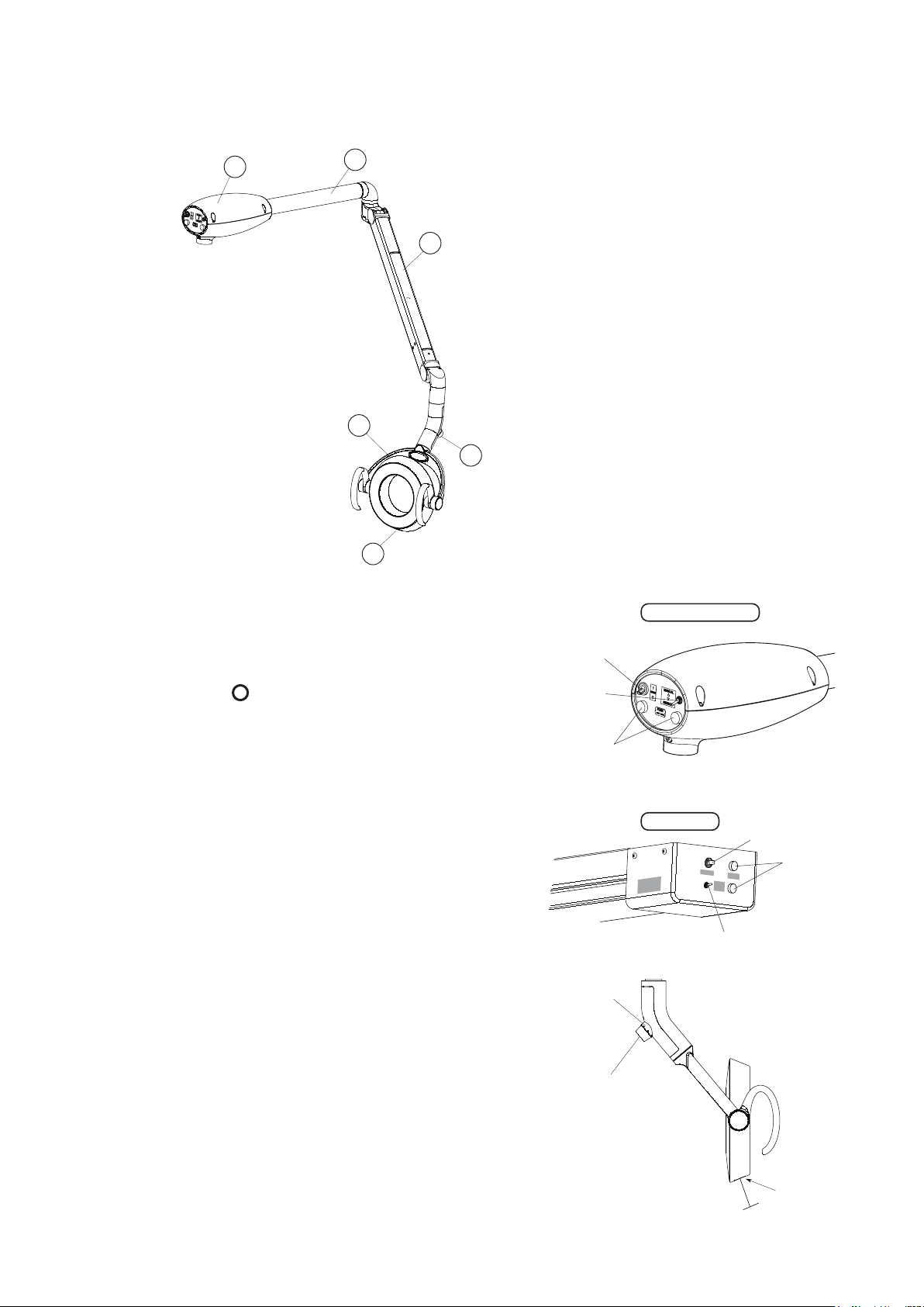
[10] OPERATING INSTRUCTIONS
1
2
3
4
5
6
Unit & Ceiling Type
Track Type
Main Switch
Fuse
Mode Selection
Switch
Main Switch
Mode Selection
Switch
Fuse
LED Display
Intensity Volume Control
Touch-less
Sensor Switch
Active distance
within 2-1/2”
10-1. Major Parts Identication
(1) LED Light Head
(2) Sensor Switch
(3) Intensity Control Volume
(4) Balance Arm
(5) Swing Arm
(6) Power Supply Box
10-2. Main Switch
Turn on the main switch to the side marked
with ' I ' .
Power on : ' I ' Mark
Power off : ' ' Mark
10-3. Mode Selection Switch
Switching modes can be changed by this switch.
This switch is located on power supply box.
Sensor : Touch-less ON/OFF and composite mode
Manual : Manual Mode (ON only)
10-4. Touch-less Switch
The light can be turned on/off with a touch-less
sensor switch. The intensities are regular operation
mode and composite mode.
10-4-1. Conrmation of mode selection switch
Make sure that the mode selection switch is at
sensor mode.
10
The touch-less switch has a sensor. The sensor
activates within the distance of 2-1/2" from the
surface. Let your hand pass by within 2-1/2" from
the touch-less sensor to turn on the light.
Let your hand pass by again to turn off.
-4-2. Turning on/off
- 20 -
Page 25
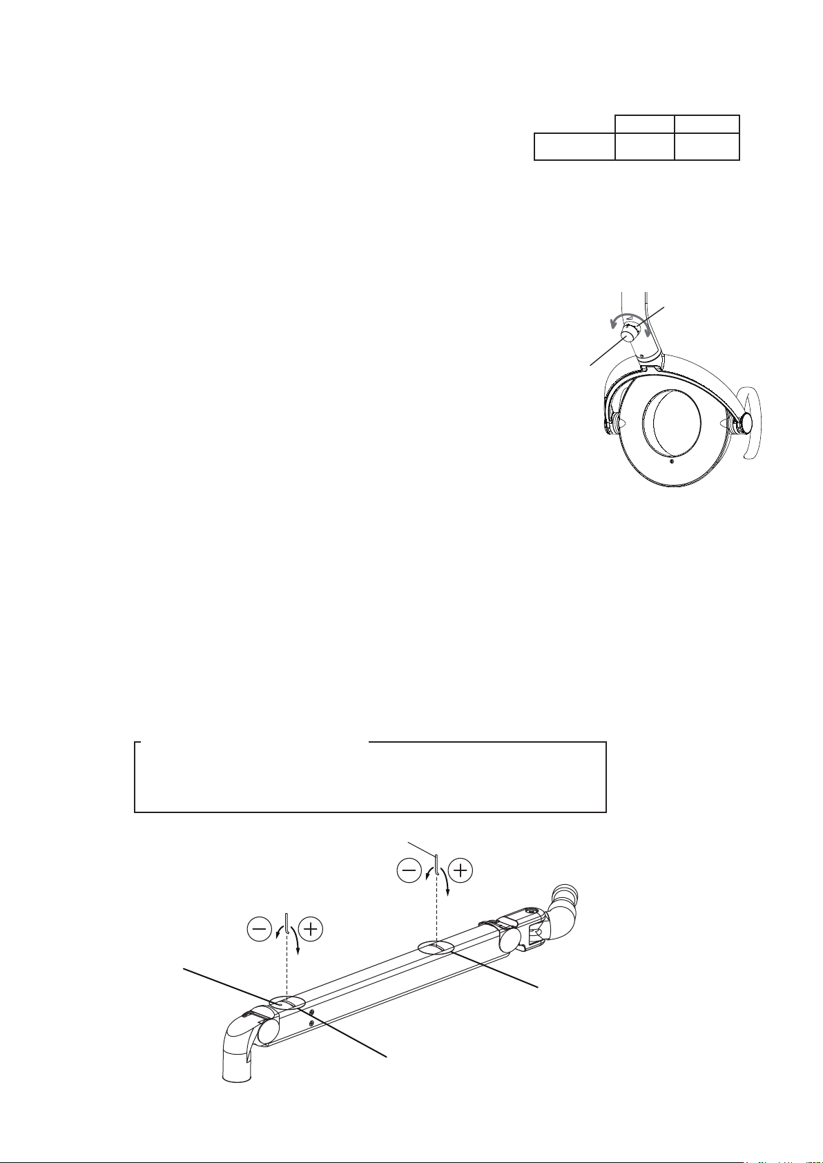
Adjustment Bar
Slot A
(for tension)
Slot B
(for angle)
Hole C
(
Socket Screw
)
Low
High
LED Display
Intensity Control
Volume
10
-4-3. Switching to the composite mode
During normal treatment mode, while the light is
on, place and hold your hand within 2-1/2" from the
touch-less sensor for 2 seconds. The light intensity
will be automatically reduced to the composite mode
which has intensity of 5500 lux.
LED display under yoke blinks green on at composite
mode.
To switch back to the normal treatment mode, place
your hand by the touch-less sensor 2 seconds again.
Note: by placing your hand for 2 seconds when the light is
off. The light does not lit in the composite mode,
but lit in normal treatment mode. Please make sure
that the light is on before lighting in composite mode.
10-5. Selection of intensity for normal treatment mode
LED display under yoke turns green on at regular
operation mode.
By turning intensity control volume, you can adjust
intensity steplessly between 4000 - 32000 Lux.
COMPOSITE
Mode
INTENSITY
5500 Lux Blink
LED Display
Note: If light intensity is set below 510 FTC and in composite mode,
light will Flash briey when exiting composite mode.
This is a normal condition indicating return to standard mode.
[11] ADJUSTING TENSION of BALANCE ARM
11-1. Adjustment of the tension of the balance arm
Position the angle of the balance arm so the tension adjustment nut becomes visible
just under slot A.
Turn the nut and adjust the tension with the adjustment bar supplied with the light.
Direction of rotation of the nut
When the light head tends to go up, turn the nut to + direction.
When the light head tends to go down, turn the nut to – direction.
- 21 -
Page 26
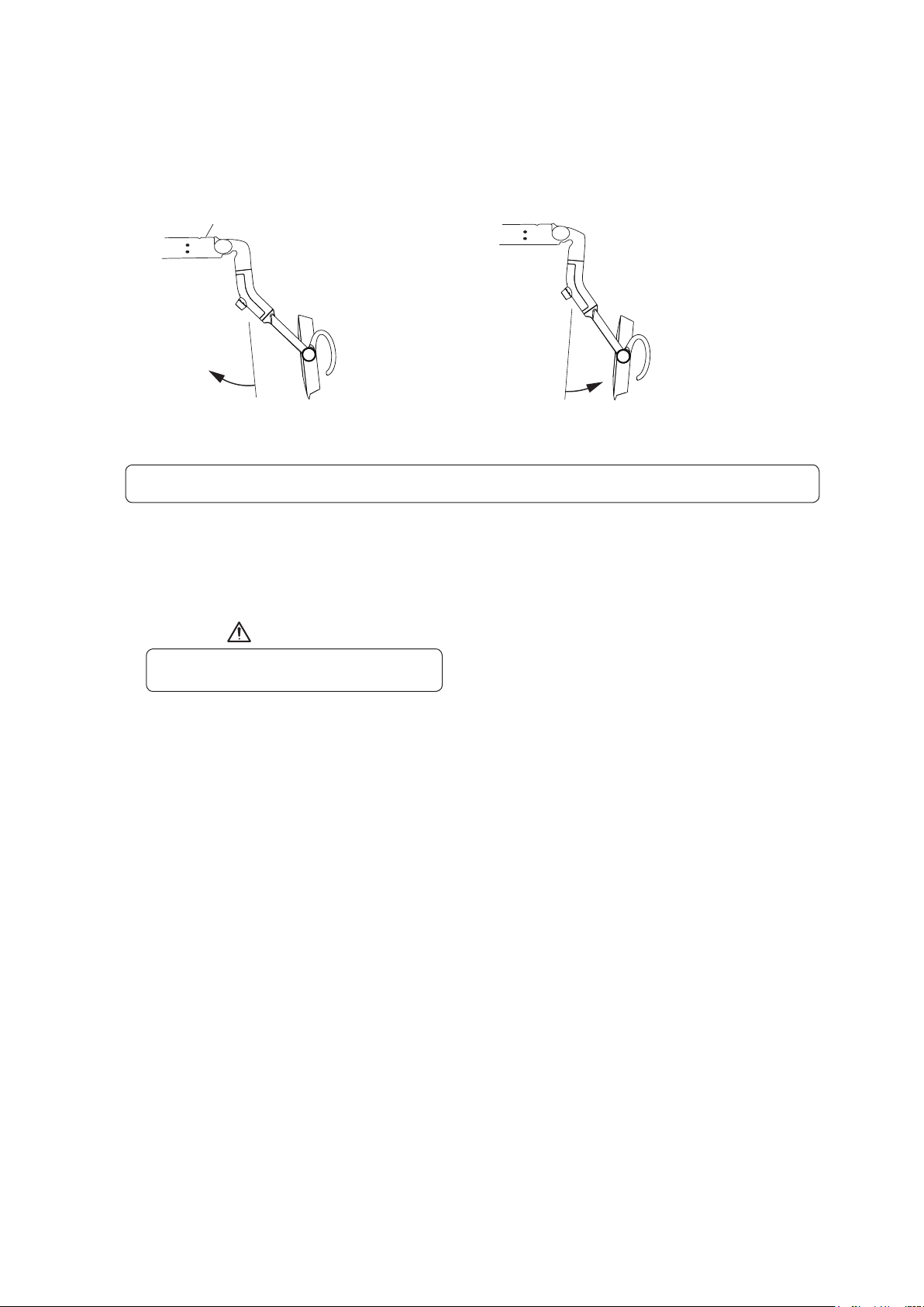
CAUTION
Hole C
When the light head tilts downward,
turn the nut to - direction.
When the light head tilts upward,
turn the nut to + direction.
11-2 Adjustment of the angle of the light head
1) Use a 2mm hex key wrench to loosen socket screw in front of Hole C.
2) Position the angle of the balance arm so the head angle adjustment nut becomes visible just under
the slot B. Turn the nut and adjust the tension with the adjustment bar supplied with the light.
3) After adjustment is done, re-tighten the socket screw.
Note : Unless this socket screw is re-tightened, the angle of the head will be changed during use.
[12] CLEANING,MAINTENANCE PARTS & DISPOSAL
12-1. Cleaning
Allow light to cool prior to cleaning.
Use a soft cloth or cotton only to gently clean surfaces. Use of other materials can scratch and
damage surfaces. Covers can be cleaned with a soft cloth or cotton moistened with alcohol.
The reector can be cleaned with a soft and dry cloth or cotton with extreme care.
12-2. Maintenance Parts
Fuse are maintenance parts.
Period for repair and supplying parts
We will supply parts of the equipment for 10 years, after the manufacturing of this equipment
is discontinued.
12-3. Lifetime
Provided that the recommended and authorized care and maintenance are correctly performed,
the working
lifetime of this equipment is 10 years from the date of initial shipment from the manufacturer.
12-4. Disposal
This is not an infectious device, but prior to disposal make sure that no parts of the device is
infected. Follow the federal, state and local regulations for disposal.
- 22 -
Page 27
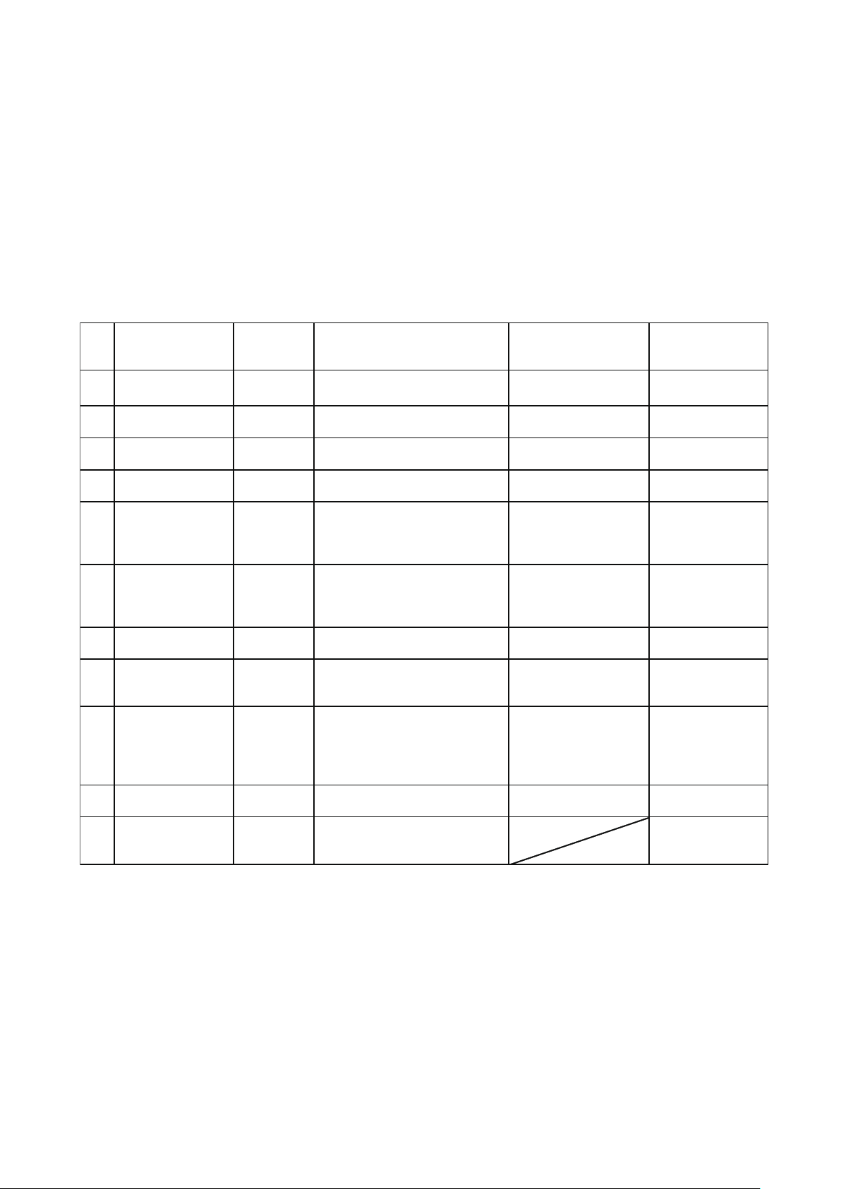
[13] MAINTENANCE AND INSPECTION
㻱㼒㻑 㻬㼗㼈㼐 㻩㼕㼈㼔㼘㼈㼑㼆㼜 㻬㼑㼖㼓㼈㼆㼗㼌㼒㼑㻃㻰㼈㼗㼋㼒㼇㻃㼄㼑㼇㻃㼇㼌㼄㼊㼑㼒㼖㼌㼖
㻬㼑㼉㼏㼘㼈㼑㼆㼈㻃㼌㼉㻃㼌㼑㼖㼓㼈㼆㼗㼌㼒㼑㻃㼌㼖
㼑㼒㼗㻃㼆㼒㼑㼇㼘㼆㼗㼈㼇
㻰㼄㼌㼑㼗㼈㼑㼄㼑㼆㼈㻃㼕㼈㼔㼘㼌㼕㼈㼇
㼌㼑㻃㼆㼄㼖㼈㻃㼒㼉
㼑㼒㼑㼆㼒㼑㼉㼒㼕㼐㼌㼗㼜
㻔
㻤㼓㼓㼈㼄㼕㼄㼑㼆㼈㻃㼒㼉㻃㻯㼈㼑㼖
㻦㼒㼙㼈㼕
㻥㼈㼉㼒㼕㼈㻃㼖㼗㼄㼕㼗
㻦㼋㼈㼆㼎㻃㼇㼈㼉㼒㼕㼐㼄㼗㼌㼒㼑㻏㻃㼖㼆㼕㼄㼗㼆㼋㼈㼖㻃㼅㼜
㼈㼜㼈㼖
㻧㼈㼗㼈㼕㼌㼒㼕㼄㼗㼌㼒㼑㻃㼒㼉㻃㼒㼓㼗㼌㼆㼄㼏
㼓㼈㼕㼉㼒㼕㼐㼄㼑㼆㼈
㻦㼋㼄㼑㼊㼈㻃㼄㻃㼏㼈㼑㼖㻃㼆㼒㼙㼈㼕㻑
㻯㼌㼊㼋㼗㻃㼖㼚㼌㼗㼆㼋 㻥㼈㼉㼒㼕㼈㻃㼖㼗㼄㼕㼗
㻶㼈㼗㻃㻶㼈㼑㼖㼒㼕㻒㻰㼄㼑㼘㼄㼏㻃㼖㼚㼌㼗㼆㼋㻃㼗㼒㻃㻰㼄㼑㼘㼄㼏㻑
㻦㼒㼑㼉㼌㼕㼐㼖㻃㼗㼋㼈㻃㼏㼌㼊㼋㼗㻃㼗㼘㼕㼑㼖㻃㼒㼑㻑
㻯㼌㼊㼋㼗㻃㼇㼒㼈㼖㼑㻊㼗㻃㼉㼘㼑㼆㼗㼌㼒㼑㻑 㻵㼈㼓㼏㼄㼆㼈㻃㼄㻃㼏㼌㼊㼋㼗㻃㼅㼘㼏㼅㻑
㻷㼒㼘㼆㼋㼏㼈㼖㼖㻃㼖㼈㼑㼖㼒㼕 㻥㼈㼉㼒㼕㼈㻃㼖㼗㼄㼕㼗
㻶㼈㼗㻃㻶㼈㼑㼖㼒㼕㻒㻰㼄㼑㼘㼄㼏㻃㼖㼚㼌㼗㼆㼋㻃㼗㼒㻃㻶㼈㼑㼖㼒㼕㻑
㻦㼒㼑㼉㼌㼕㼐㼖㻃㼗㼋㼈㻃㼏㼌㼊㼋㼗㻃㼗㼘㼕㼑㼖㻃㼒㼑㻑
㻯㼌㼊㼋㼗㻃㼇㼒㼈㼖㼑㻊㼗㻃㼉㼘㼑㼆㼗㼌㼒㼑㻑
㻦㼏㼈㼄㼑㻃㼗㼋㼈㻃㼖㼈㼑㼖㼒㼕
㼖㼘㼕㼉㼄㼆㼈㻑
㻬㼑㼗㼈㼑㼖㼌㼗㼜㻃㼖㼚㼌㼗㼆㼋 㻥㼈㼉㼒㼕㼈㻃㼖㼗㼄㼕㼗 㻦㼋㼄㼑㼊㼈㻃㼌㼑㼗㼈㼑㼖㼌㼗㼜㻑
㻬㼗㻃㼐㼄㼜㻃㼆㼄㼘㼖㼈㻃㼗㼋㼈㻃㼇㼌㼉㼉㼌㼆㼘㼏㼗㼜
㼄㼗㻃㼇㼈㼑㼗㼄㼏㻃㼓㼕㼄㼆㼗㼌㼆㼈㻑
㻷㼘㼕㼑㻃㼒㼉㼉㻃㼗㼋㼈㻃㼏㼌㼊㼋㼗㻑㻃㻦㼄㼏㼏
㼆㼘㼖㼗㼒㼐㼈㼕㻃㼖㼈㼕㼙㼌㼆㼈㻑
㻩㼘㼑㼆㼗㼌㼒㼑㼄㼏㼌㼗㼜㻃㼒㼉
㻥㼄㼏㼄㼑㼆㼈㻃㻤㼕㼐
㻥㼈㼉㼒㼕㼈㻃㼖㼗㼄㼕㼗
㻶㼚㼌㼑㼊㻃㼗㼋㼈㻃㼅㼄㼏㼄㼑㼆㼈㻃㼄㼕㼐㻃㼘㼓㻒㼇㼒㼚㼑㻑
㻶㼚㼌㼑㼊㻃㼗㼋㼈㻃㼅㼄㼏㼄㼑㼆㼈㻃㼄㼕㼐㻃㼕㼌㼊㼋㼗㻒㼏㼈㼉㼗㻑
㻰㼄㼎㼈㻃㼖㼘㼕㼈㻃㼗㼋㼈㻃㼅㼄㼏㼄㼑㼆㼈㻃㼄㼕㼐㻃㼖㼗㼒㼓㼖㻃㼄㼑㼇
㼋㼒㼏㼇㼖㻃㼌㼗㼖㻃㼓㼒㼖㼌㼗㼌㼒㼑㻑
㻯㼌㼊㼋㼗㻃㼋㼈㼄㼇㻃㼇㼒㼈㼖㼑㻊㼗㻃㼖㼗㼄㼜㻃㼄㼗
㼗㼋㼈㻃㼇㼈㼖㼌㼕㼈㼇㻃㼓㼒㼖㼌㼗㼌㼒㼑㻑
㻤㼇㼍㼘㼖㼗㻃㼗㼋㼈㻃㼗㼈㼑㼖㼌㼒㼑㻃㼒㼉
㼗㼋㼈㻃㼅㼄㼏㼄㼑㼆㼈㻃㼄㼕㼐㻑
㻩㼒㼏㼏㼒㼚㻃㼌㼑㼖㼗㼕㼘㼆㼗㼌㼒㼑㼖㻃㼒㼑
㼓㼄㼊㼈㻃㻕㻔㻑
㻹㼈㼕㼗㼌㼆㼄㼏㻃㼕㼒㼗㼄㼗㼌㼒㼑㻃㼒㼉㻃㼗㼋㼈
㻯㼌㼊㼋㼗㻃㼋㼈㼄㼇
㻥㼈㼉㼒㼕㼈㻃㼖㼗㼄㼕㼗
㻵㼒㼗㼄㼗㼈㻃㼗㼋㼈㻃㼏㼌㼊㼋㼗㻃㼋㼈㼄㼇㻃㼘㼓㻒㼇㼒㼚㼑㻑㻃㻰㼄㼎㼈
㼖㼘㼕㼈㻃㼗㼋㼈㻃㼏㼌㼊㼋㼗㻃㼋㼈㼄㼇㻃㼖㼗㼒㼓㼖㻃㼄㼑㼇㻃㼋㼒㼏㼇㼖㻃㼌㼗㼖
㼓㼒㼖㼌㼗㼌㼒㼑㻑
㻯㼌㼊㼋㼗㻃㼋㼈㼄㼇㻃㼇㼒㼈㼖㼑㻊㼗㻃㼖㼗㼄㼜㻃㼄㼗
㼗㼋㼈㻃㼇㼈㼖㼌㼕㼈㼇㻃㼓㼒㼖㼌㼗㼌㼒㼑㻑
㻤㼇㼍㼘㼖㼗㻃㼗㼋㼈㻃㼗㼈㼑㼖㼌㼒㼑㻃㼒㼉
㼙㼈㼕㼗㼌㼆㼄㼏㻃㼕㼒㼗㼄㼗㼌㼒㼑㻑
㻩㼒㼏㼏㼒㼚㻃㼌㼑㼖㼗㼕㼘㼆㼗㼌㼒㼑㼖㻃㼒㼑
㼓㼄㼊㼈㻃㻕㻕㻑
㻯㼌㼊㼋㼗㻃㼋㼈㼄㼇㻃㼄㼑㼊㼏㼈 㻥㼈㼉㼒㼕㼈㻃㼖㼗㼄㼕㼗
㻦㼒㼑㼉㼌㼕㼐㼖㻃㼗㼋㼈㻃㼏㼌㼊㼋㼗㻃㼋㼈㼄㼇㻃㼌㼖㻃㼙㼈㼕㼗㼌㼆㼄㼏㼏㼜
㼄㼏㼌㼊㼑㼈㼇㻑
㻯㼌㼊㼋㼗㻃㼋㼈㼄㼇㻃㼇㼒㼈㼖㼑㻊㼗㻃㼖㼗㼄㼜㻃㼄㼗
㼗㼋㼈㻃㼇㼈㼖㼌㼕㼈㼇㻃㼓㼒㼖㼌㼗㼌㼒㼑㻑
㻤㼇㼍㼘㼖㼗㻃㼗㼋㼈㻃㼄㼑㼊㼏㼈㻃㼒㼉㻃㼗㼋㼈
㼏㼌㼊㼋㼗㻃㼋㼈㼄㼇㻑
㻯㼌㼊㼋㼗㻃㼋㼈㼄㼇㻃㼕㼒㼗㼄㼗㼌㼒㼑 㻥㼈㼉㼒㼕㼈㻃㼖㼗㼄㼕㼗
㻵㼒㼗㼄㼗㼈㻃㼗㼋㼈㻃㼏㼌㼊㼋㼗㻃㼋㼈㼄㼇㻃㼕㼌㼊㼋㼗㻒㼏㼈㼉㼗㻑㻃㻰㼄㼎㼈
㼖㼘㼕㼈㻃㼗㼋㼈㻃㼏㼌㼊㼋㼗㻃㼕㼒㼗㼄㼗㼈㻃㻔㻙㻓㼲㻃㼗㼒㻃㼈㼄㼆㼋
㼇㼌㼕㼈㼆㼗㼌㼒㼑㻑
㻯㼌㼊㼋㼗㻃㼋㼈㼄㼇㻃㼕㼒㼗㼄㼗㼈㼖㻃㼉㼕㼈㼈㼏㼜㻑
㻷㼋㼌㼖㻃㼐㼄㼜㻃㼆㼄㼘㼖㼈㻃㼗㼋㼈
㼖㼑㼄㼓㼓㼌㼑㼊㻃㼒㼉㻃㼄㻃㼚㼌㼕㼈㻑
㻦㼄㼏㼏㻃㼆㼘㼖㼗㼒㼐㼈㼕㻃㼖㼈㼕㼙㼌㼆㼈㻑
㻦㼄㼕㼈㻃㼈㼛㼗㼈㼕㼌㼒㼕 㻥㼈㼉㼒㼕㼈㻃㼖㼗㼄㼕㼗
㻦㼋㼈㼐㼌㼆㼄㼏㻃㼄㼑㼇㻃㼇㼌㼕㼗㻃㼒㼑㻃㼗㼋㼈㻃㼓㼕㼒㼇㼘㼆㼗
㼈㼛㼗㼈㼕㼌㼒㼕㻃㼐㼘㼖㼗㻃㼅㼈㻃㼆㼏㼈㼄㼑㼈㼇㻑
㻧㼌㼖㼆㼒㼏㼒㼕㼄㼗㼌㼒㼑㻃㼄㼑㼇
㼇㼈㼗㼈㼕㼌㼒㼕㼄㼗㼌㼒㼑㻃㼗㼒㻃㼗㼋㼈
㼈㼛㼗㼈㼕㼌㼒㼕㻏㻃㼄㼑㼇㻃㼆㼒㼕㼕㼒㼖㼌㼒㼑㻃㼄㼑㼇
㼕㼘㼖㼗㼌㼑㼊㻃㼗㼒㻃㼐㼈㼗㼄㼏㼏㼌㼆
㼆㼒㼐㼓㼒㼑㼈㼑㼗㼖㻃㼐㼄㼜㻃㼄㼕㼌㼖㼈㻑
㻨㼛㼈㼆㼘㼗㼈㼖㻃㼚㼌㼓㼌㼑㼊㻃㼌㼑
㼄㼆㼆㼒㼕㼇㼄㼑㼆㼈㻃㼚㼌㼗㼋
㻅㻦㼏㼈㼄㼑㼌㼑㼊
㻬㼑㼖㼗㼕㼘㼆㼗㼌㼒㼑㼖㻅
㻲㼗㼋㼈㼕㻃㻔
㻲㼑㼆㼈㻃㼈㼙㼈㼕㼜
㼚㼈㼈㼎
㻰㼄㼎㼈㻃㼖㼘㼕㼈㻃㼗㼋㼄㼗㻃㼑㼒㻃㼄㼅㼑㼒㼕㼐㼄㼏㻃㼑㼒㼌㼖㼈
㼒㼆㼆㼘㼕㼖㻃㼚㼋㼈㼑㻃㼗㼋㼈㻃㼓㼕㼒㼇㼘㼆㼗㻃㼌㼖㻃㼒㼓㼈㼕㼄㼗㼈㼇㻑
㻯㼌㼊㼋㼗㻃㼐㼄㼜㻃㼑㼒㼗㻃㼉㼘㼑㼆㼗㼌㼒㼑
㼕㼌㼊㼋㼗㻑
㻷㼘㼕㼑㻃㼒㼉㼉㻃㼗㼋㼈㻃㼏㼌㼊㼋㼗㻑㻃㻦㼄㼏㼏
㼆㼘㼖㼗㼒㼐㼈㼕㻃㼖㼈㼕㼙㼌㼆㼈㻑
㻲㼗㼋㼈㼕㻃㻕 㻃
㻬㼉㻃㼗㼋㼈㻃㼏㼌㼊㼋㼗㻃㼋㼄㼖㻃㼑㼒㼗㻃㼅㼈㼈㼑㻃㼘㼖㼈㼇㻃㼉㼒㼕㻃㼄
㼏㼒㼑㼊㻃㼗㼌㼐㼈㻏㻃㼐㼄㼎㼈㻃㼖㼘㼕㼈㻃㼗㼋㼈㻃㼏㼌㼊㼋㼗
㼉㼘㼑㼆㼗㼌㼒㼑㼖㻃㼆㼒㼕㼕㼈㼆㼗㼏㼜㻃㼄㼑㼇㻃㼖㼄㼉㼈㼏㼜㻑
㻬㼉㻃㼗㼋㼈㻃㼏㼌㼊㼋㼗
㼐㼄㼏㼉㼘㼑㼆㼗㼌㼒㼑㼖㻏㻃㼆㼄㼏㼏
㼆㼘㼖㼗㼒㼐㼈㼕㻃㼖㼈㼕㼙㼌㼆㼈㻑
㻕
㻖
㻗
㻘
㻙
㻚
㻛
㻜
㻔㻓
㻔㻔
Guide for daily maintenance and inspection (Maintenance and inspection by user)
Management of maintenance and inspection of medical equipment should be implemented by the
user (medical inspection). In case the user does not implement such management, it is permitted
that such management is outsourced to a qualified entity such as a medical equipment repair
company.
For safe use of this product, it is necessary that inspection should be conducted in the specied
frequency on the items described below.
- 23 -
Page 28
R
NOTE
BELMONT EQUIPMENT, Division of Takara Belmont USA, Inc.
101 Belmont Drive Somerset, New Jersey 08873 U.S.A. TEL.:(732) 469-5000 / (800) 223-1192 Fax.:(732)356-1035
TAKARA CO, CANADA LTD.
2076 S. Sheridan Way, Mississauga, Ont., L5J2M4, Can. TEL.:(905) 822-2755 Fax.:(905)822-6203
TAKARA BELMONT CORPORATION (Manufacturer)
1-1, 2-Chome, Higashi-shinsaibashi,Chuo-ku,Osaka,Japan TEL.: 81-6-6213-5945 FAX.: 81-6-6212-3680
Book No. 1E02FAD0
Printed in Japan 2012-08
 Loading...